Article

Developing a Wearable Turbine-Based Energy Harvesting System for the Motorcycle Helmet Application


by
Younghwan Kim
1 and
Hyunseung Lee
2,*
1
Department of Fashion Design, Semyung University, Jecheon 27136, Republic of Korea
2
Department of Fashion Industry, Incheon National University, Incheon 22012, Republic of Korea
*
Author to whom correspondence should be addressed.
Appl. Sci. 2026, 16(7), 3482; https://doi.org/10.3390/app16073482
Submission received: 6 March 2026 / Revised: 28 March 2026 / Accepted: 31 March 2026 / Published: 2 April 2026

Featured Application

This study leverages aerodynamic flow (wind pressure/velocity) generated during motorcycle riding as an energy source and demonstrates the feasibility of a compact wind-turbine-based wearable energy-harvesting system integrable into a helmet. By optimizing housing and blade geometries to improve power-generation efficiency and embedding a functional prototype—incorporating a power-boosting circuit—into an actual helmet form factor, the work supports potential use as an auxiliary power supply for low-power wearable electronic devices. The proposed concept further provides a basis for extending individual-scale renewable energy harvesting to related contexts, such as bicycles/personal mobility platforms, as well as protective equipment (PPE) used in wind-exposed occupational environments.

Abstract

This study investigated the feasibility of a wearable wind energy-harvesting system integrated into a motorcycle helmet that converts riding-induced airflow into storable electrical energy. A compact horizontal-axis turbine-based system was designed and optimized through staged experiments focusing on generator selection, housing geometry, rotor configuration, and circuit-connected performance. A medium-scale generator, diffuser-type housing (Hd), and eight-blade pinwheel rotor (Rb) were identified as the most suitable combination for helmet-scale integration. The final prototype incorporated two side-mounted turbine modules, a crown-mounted harvesting–boost circuit, and a detachable rechargeable battery pack within a full-face helmet platform. In a field-based riding experiment, the prototype produced mean outputs of 3.99 V, 39.51 mA, and 157.64 mW at 30 km/h; 4.43 V, 43.48 mA, and 192.61 mW at 40 km/h; and 5.45 V, 53.53 mA, and 291.73 mW at 50 km/h. A static wearability evaluation with six participants indicated no obvious discomfort under a quasi-riding posture. These findings support the practical feasibility of helmet-integrated wind energy harvesting as an auxiliary power source for low-power wearable electronics, while highlighting the need for future studies on aerodynamic validation, dynamic wearability, acoustic burden, and safety-oriented structural refinement.

1. Introduction

As global attention to sustainability and distributed renewable energy systems continues to grow, wearable energy harvesting has emerged as a promising strategy for powering low-power personal electronics while mitigating reliance on frequent external charging. Recent studies have demonstrated that wearable harvesters can utilize diverse energy sources, including body motion, thermal gradients, solar energy, and ambient mechanical stimuli; however, many existing systems still deliver limited output under real-world operating conditions, and the gap between harvested energy and the power demands of practical wearable devices remains a major challenge [1,2,3].
Among the various approaches to energy harvesting, wind-based conversion is attractive because aerodynamic flow can potentially yield a stronger, more continuous input than many body motion-based mechanisms under conditions of elevated relative airspeed. Recent reviews of small-scale wind turbines have emphasized their potential as auxiliary power sources for low-power electronics and distributed sensing applications, particularly when paired with rectification, boosting, and energy-storage circuitry. Nevertheless, most prior wearable energy-harvesting studies have focused on piezoelectric, thermoelectric, triboelectric, or photovoltaic mechanisms, whereas comparatively few studies have examined helmet-integrable wind turbine systems that exploit airflow generated during actual vehicular operation [1,3,4].
This research context is especially relevant to motorcycles. Because motorcyclists are directly exposed to ambient airflow during travel, the motorcycle constitutes an operating environment in which aerodynamic loading substantially exceeds that encountered during ordinary walking or routine body motion. Accordingly, a helmet-mounted harvesting system that uses riding-induced airflow may represent a practically viable pathway for personal-scale auxiliary power generation while remaining compatible with the mandatory protective equipment already worn by riders [5]. More broadly, recent studies indicate that the performance of small-scale mechanical energy harvesters is strongly influenced not only by the energy conversion mechanism itself but also by structural configuration and system-level integration, suggesting that structural design constitutes a critical consideration in developing wearable energy harvesting systems [1,3,6].
Accordingly, this study aims to develop a prototype wearable energy-harvesting system integrated into a motorcycle helmet, exploiting aerodynamic pressure generated during operation as the primary energy source. While earlier studies have demonstrated the general feasibility of vehicle-mounted micro wind turbines [7], the present work makes distinct contributions by: (1) systematically optimizing turbine housing geometry and fan blade configuration to suit helmet-scale geometric constraints; (2) integrating a boost-converter circuit and rechargeable battery into a wearable prototype that achieves practical charging output; and (3) evaluating wearability under quasi-static conditions as a first step toward dynamic assessment. The research objectives and scope undertaken to achieve this aim are as follows. First, a wearable energy-harvesting system is developed with dimensions and mass compatible with helmet-mounted motorcycle operation. Because the turbine constitutes the heaviest subsystem, component selection is restricted to compact, lightweight motor assemblies suitable for integration into the space-constrained geometry of a helmet-based wearable platform. Second, the fan blade geometry and turbine housing architecture are optimized to achieve rotational efficiency sufficient to charge the 3.7 V battery representative of those embedded in typical mobile devices, within the constraints of a compact wearable turbine system. The design exploration for blade and housing configurations is limited to small-scale dimensions compatible with helmet-based installation. Third, a wind energy harvesting system prototype incorporating the resulting design parameters is developed, and its wearability and power generation performance are validated through experimental evaluation. By integrating wind energy harvesting functionality into a motorcycle helmet—a mandatory protective device for riders—this study proposes an accessible pathway toward diversifying personal-scale electricity generation and addressing contemporary energy sustainability challenges.

2. Related Study

2.1. Wearable Energy Harvesting

Wearable energy harvesting encompasses technologies that convert energy from the user’s immediate environment, or generated by the human body itself, into electrical energy that can be stored or directly used by electronic systems. Representative sources include solar irradiance, body heat, mechanical deformation, pressure, vibration, and motion. Recent reviews have emphasized that wearable harvesting technologies have progressed rapidly in terms of material flexibility, miniaturization, and integration into garments and accessories; however, their practical deployment remains constrained by the relatively small amount of harvested power, intermittency of environmental inputs, and the need for efficient power-management and storage circuitry [1,2,3].
Previous studies have proposed wearable harvesting systems for gloves, wristbands, sleeves, jackets, shoes, and smart textiles, employing piezoelectric, thermoelectric, photovoltaic, triboelectric, and electromagnetic principles. For example, piezoelectric and triboelectric systems have been applied to capture repetitive pressure or motion during grasping and walking, while solar and thermoelectric systems have been integrated into wrist- and arm-worn platforms to exploit outdoor light exposure and body–environment temperature gradients. These studies demonstrate that wearable platforms can serve as practical energy-harvesting interfaces, while also showing that power generation is highly dependent on the user’s posture, motion patterns, and ambient environmental conditions [8,9,10].
A notable tendency in recent research is the shift from single-source harvesting toward multisource or hybrid systems. For instance, head- or wrist-worn systems combining photovoltaic and thermoelectric modules have been proposed to improve temporal stability in conditions where one source is weak or unavailable. In one representative study, a hybrid wearable system for head- and wrist-worn healthcare devices stored harvested energy in a 3.7 V, 300 mAh lithium battery and supported a 34 mW load under hybrid operating conditions, illustrating the critical importance of source combination and power-conditioning design for real-world wearable applications [11]. This trend indicates that the central issue is no longer merely whether energy can be harvested, but whether sufficient usable energy can be generated and managed under realistic wear conditions.
Despite this progress, most wearable energy harvesters continue to rely on relatively weak sources, such as localized body pressure, joint motion, small thermal gradients, or limited solar exposure. It is precisely in this regard that the present study differs conceptually. Rather than relying solely on low-intensity body-generated energy, it focuses on a use environment in which the user is exposed to sustained, high-relative-velocity airflow during motorcycle riding. From the perspective of wearable power generation, such a scenario provides a distinct energy input condition, fundamentally different from that of ordinary ambulatory wearables. Therefore, the value of the present study lies not in revisiting generic wind energy conversion but in exploring whether a compact turbine system can be integrated into a mandatory wearable protective platform and yield practically useful electrical output under riding-related airflow conditions.
Prior investigations have proposed wearable energy-harvesting systems leveraging platforms such as gloves, jackets, wristbands, and footwear, drawing on diverse energy sources, including solar irradiance, mechanical pressure, body heat, and magnetic fields. Utilizing body-worn platforms, these systems harvest mechanical energy generated by the wearer’s movements, thermoregulatory heat dissipation, and incident solar energy. Three of the reviewed studies adopted technical approaches that exploit pressure from human motion or mechanical loads transmitted through clothing [12,13,14], while three additional studies investigated harvesting systems employing solar cells mounted on garments, wristbands, or other wearable form factors [15,16]. Because mechanical pressure is unavoidably applied to specific body regions during human activity, and solar irradiation represents one of the ambient energy sources most amenable to miniaturized, wearable-scale generators, these two power generation principles have been widely adopted in prior research.
The studies summarized in Table 1 represent meaningful contributions to environmentally sustainable energy recovery, as the devices are worn on the body and harness user-generated mechanical or ambient environmental energy during occupational or everyday activities. However, except for the system employing 16 solar panels in combination with thermoelectric materials [15], systems relying on a limited number of harvesters and drawing solely on ambient exposure and human motion energy tend to yield modest power outputs, which may appear insufficient for practical applications, such as battery charging, from a user’s perspective.
Addressing this limitation, the present study implements a turbine-based power generation system integrated into a body-worn platform. The system harnesses the aerodynamic pressure acting on the helmet during motorcycle operation—substantially greater than that encountered during human ambulatory activities—as the primary energy input for individual-scale electrical power generation.

2.2. Turbine Power Generation

Turbine-based energy harvesting converts the kinetic energy of moving air or fluid into rotational mechanical energy, which is then converted into electricity through electromechanical transduction. In wind-driven systems, the physically available power in the flow is governed by air density, swept area, and wind velocity, such that output potential increases rapidly with flow speed. For this reason, small wind turbines have been actively considered as auxiliary power sources for low-power electronics and Internet of Things (IoT) applications, especially where continuous airflow is available [4]. From a system-design perspective, actual usable power depends not only on the wind resource itself but also on rotor geometry, startup behavior, electrical loading, rectification, and storage efficiency.
The two representative mechanical architectures of wind turbines are the horizontal-axis wind turbine (HAWT) and the vertical-axis wind turbine (VAWT). HAWTs are generally favored for higher aerodynamic efficiency when airflow direction is relatively stable and aligned with the rotor axis. In contrast, VAWTs are often regarded as advantageous in low-speed, multidirectional, or turbulent urban wind environments because they can operate without active yaw alignment. However, VAWTs generally exhibit lower aerodynamic efficiency than HAWTs, and several VAWT subtypes are susceptible to negative torque or reduced performance during parts of the rotation cycle [18,19]. Overall benefit and drawback are summarized in Table 2.
The HAWT extracts wind energy about a horizontal rotational axis and employs blades oriented parallel to the ground. Aerodynamic lift induces blade rotation as oncoming airflow impinges on the blade surface at right angles. Conventional airfoil blades are commonly employed for utility-scale installations, whereas designs for small-scale applications may adopt spinning-top blade geometries to enhance compactness. The principal advantages of HAWTs are that, under steady wind conditions, they achieve higher conversion efficiency than VAWTs and do not exhibit the backtracking effect. Their primary limitations include strong dependence on wind direction, which constrains performance in environments where wind strength and direction are highly variable [20,21,22,23]. The aerodynamic performance of a HAWT rotor can be characterized by the Betz limit, which establishes the theoretical maximum power extraction coefficient of 16/27 (≈0.593) for any wind turbine operating in a free stream. For micro-scale HAWTs subject to low Reynolds number effects (Re < 105), aerodynamic losses due to laminar separation and blade-tip vortices result in practical power coefficients substantially below this theoretical bound, typically in the range of 0.20–0.45 [24]. Recognizing these constraints, the present study employs an empirical optimization strategy rather than analytical blade design, selecting and testing candidate turbine units and housing geometries to identify configurations that maximize output under the specific aerodynamic conditions imposed by motorcycle operation.
The VAWT operates according to the principle of the earliest windmills, with blades rotating about an axis perpendicular to the ground. Blade architectures are commonly grouped into two canonical designs: Savonius rotors, which are drag-driven and function analogously to a waterwheel, and Darrieus rotors, which employ aerodynamic airfoils to generate lift and drive rotation. Unlike HAWTs, which require relatively steady, well-aligned winds to achieve peak efficiency, VAWTs can generate power independently of wind direction and operate at lower wind speeds, making them particularly suitable for urban environments with slower, more turbulent airflow. However, VAWTs generally exhibit low starting torque and dynamic stability limitations that reduce efficiency under high-wind conditions. Moreover, because the blades periodically move against the prevailing wind direction during rotation, they are susceptible to backtracking (negative torque) losses [20,25,26,27].
Given the design requirements for a compact wind-energy system mountable on a motorcycle helmet, a HAWT configuration was selected for the present study. This configuration was considered particularly appropriate because it is well-suited to capturing horizontally directed airflow generated along the motorcycle’s direction of travel.
Recent studies have also emphasized that, in small wind-energy systems, geometric optimization factors, such as blade profile, blade pitch, and diffuser–confuser housing design, are critically important. In particular, studies on small HAWTs have reported that casing structures can alter the flow field around the rotor and thereby affect actual power output, while rotor geometry directly influences startup characteristics and power coefficient. These findings support the validity of the present study’s design approach, which experimentally varied both the turbine housing and rotor geometry, rather than applying scaled-down blade-design principles derived from large wind turbines [28,29].
Although a fully integrated analytical model combining blade element momentum (BEM) theory and computational fluid dynamics (CFD) would provide the most rigorous framework for characterizing a microturbine system [24], the present study was deliberately scoped as an empirical proof-of-concept investigation. The experimental approach was designed to explore the parameter space of housing geometries and blade configurations within the dimensional constraints imposed by helmet integration, with voltage and power output serving as the primary performance indicators. The development of a physics-based analytical model that integrates rotor aerodynamics, housing duct flow, and generator electromagnetic loading to relate turbine geometry to electrical power output is proposed as a priority for future research.

3. Materials and Methods

3.1. Harvesting System Design

Because the proposed harvesting system was intended for integration into a motorcycle helmet, the design process was constrained to minimize mass, protrusion, and rotational imbalance while still achieving charge-relevant electrical output. Accordingly, the harvesting system was developed across three consecutive stages: (1) generator selection, (2) turbine housing design, and (3) rotor/fan design. In the first stage, three commercially available micro-DC motors used as generators were screened to identify a candidate that offers an acceptable compromise among cut-in behavior, output level, and size compatibility for helmet mounting. In the second and third stages, alternative housing and rotor geometries were designed to improve aerodynamic capture and rotational efficiency under riding-relevant airflow conditions. This staged screening approach is consistent with recent small wind turbine development studies, which emphasize that rotor performance should be evaluated alongside geometric constraints, startup behavior, and application-specific operating conditions rather than solely by nominal output values [30,31].
Preliminary testing for the generator screening was conducted on a day with relatively weak ambient wind (3 m/s), measured at the test site with a handheld anemometer, with wind direction predominantly headwind relative to the direction of travel, within ±15°. It should be noted that the relative wind speed experienced by the turbine represents the vector sum of the vehicle’s travel velocity and the ambient wind velocity. Under the conditions of this test—with a near-headwind orientation—the ambient wind contribution augmented the relative airflow by approximately 3 m/s above the vehicle speed at each test level. In a crosswind or tailwind scenario, the influence on turbine-facing airflow would differ substantially: a direct crosswind at 3 m/s would contribute negligibly to the axial (turbine-facing) airflow component, while a direct tailwind would reduce it. This directional sensitivity is consistent with the aerodynamic behavior of HAWT systems, which achieve maximum efficiency when the rotor axis is aligned with the incoming flow direction [24,32]. Future testing should incorporate a systematic variation in ambient wind direction, including headwind, crosswind, and tailwind conditions, to fully characterize the influence of ambient wind angle on turbine output.
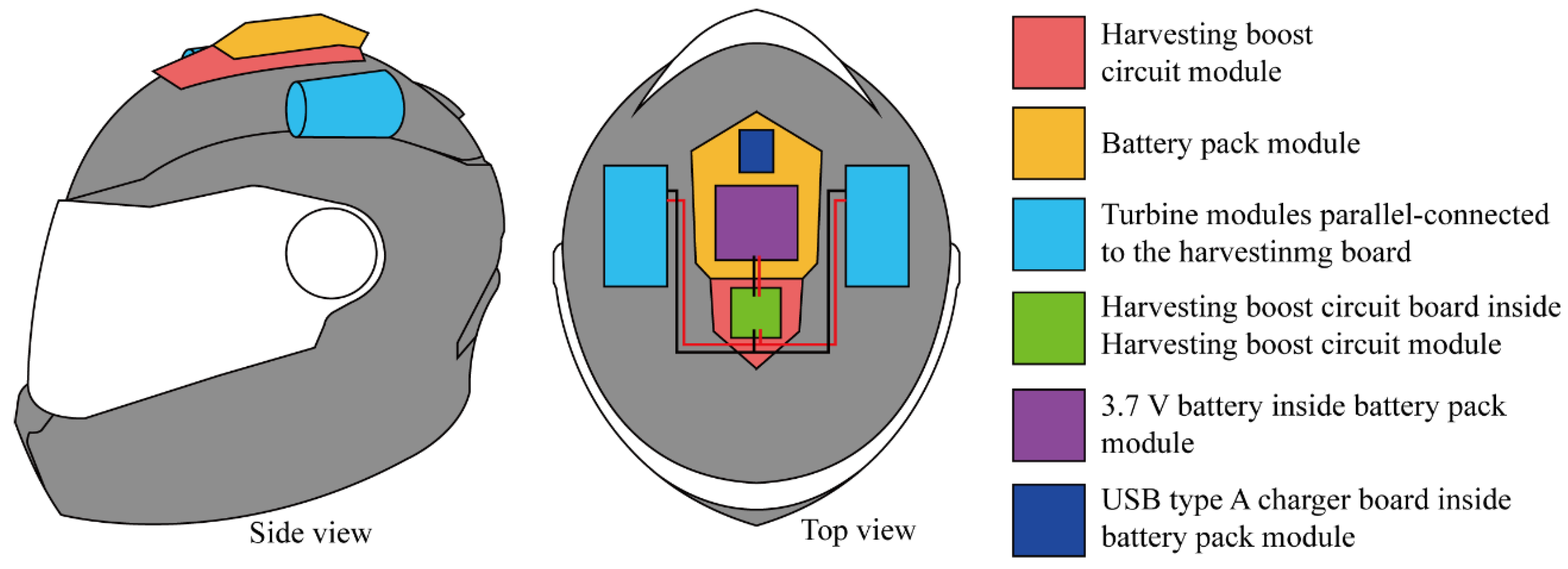
As shown in Table 3, among the three generator candidates, the small unit showed the lowest cut-in threshold, initiating rotation even at 10 km/h, indicating a startup advantage under weak airflow. However, its generated voltage remained comparatively low across the test range. By contrast, the medium unit did not rotate at the two lowest test speeds but exhibited more practically useful voltage output from 30 km/h onward, reaching 6.58 V at 50 km/h. The large unit produced the highest voltage at 40–50 km/h; however, its inability to operate below 40 km/h and its substantially greater mass rendered it less suitable for helmet integration. Considering the trade-off among startup behavior, usable voltage level, and wearable mass constraints, the medium generator was selected as the basis for subsequent housing and rotor design. This selection logic is consistent with the practical design principle that small wearable wind harvesters must be optimized not for peak output alone, but for a balanced combination of cut-in characteristics, device mass, and usable operating range [31,33]. Accordingly, the overall architecture of the harvesting system was developed around the medium turbine, which exhibited intermediate performance characteristics between the small and large units (Figure 1).
The overall system architecture is described as follows. The harvesting–boost module, which consists of a boost-conversion circuit board that conditions the turbine output for battery charging and a rechargeable battery, is mounted at the bregma of the helmet to preserve center-of-mass balance and optimize battery charging performance. The boost-conversion circuit and battery modules are structurally designed to be separable and reattachable, allowing the user to detach the charged battery for ancillary applications such as charging mobile devices. The turbine modules responsible for power generation are mounted symmetrically on the left and right sides of the harvesting and battery modules to minimize adverse effects on helmet mass distribution. The charging current delivered to the battery is amplified by connecting the outputs of the two turbines in parallel on the harvesting circuit board.

3.1.1. Turbine Housing

Although removing the housing could reduce blockage and maximize the rotor’s direct exposure to airflow, an exposed rotor is vulnerable to impacts from debris, raindrops, or foreign objects during actual riding. Therefore, the housing was designed not only as an aerodynamic guide but also as a protective structural component for the fan, generator, and electrical connections. Four housing designs emphasizing air intake and exhaust characteristics were developed to leverage the duct augmentation effect reported in prior studies [32,34,35]. The theoretical basis for housing-induced augmentation lies in the pressure differential created between the housing inlet and outlet: a converging inlet section accelerates incoming flow toward the rotor plane by reducing the cross-sectional area (nozzle effect), while a diverging outlet section reduces back pressure downstream of the rotor, thereby drawing additional mass flow through the turbine (diffuser effect). Experimental studies on flanged-diffuser shrouded turbines have demonstrated power augmentation of approximately 4–5 times that of unshrouded turbines of equivalent diameter, driven primarily by a low-pressure vortex region formed behind the diffuser flange [34]. This design rationale is consistent with previous small wind turbine studies showing that confusor/diffuser shaping and inlet–outlet geometry can substantially alter local flow distribution and, consequently, rotational efficiency [28,36]. More recent optimization studies have confirmed that the improved duct geometry can increase the inlet wind speed by up to 2.14 at the throat position compared to an unducted configuration [35]. The four housing designs evaluated in this study systematically explore this design space at a microscale suitable for helmet integration (Table 4).
Type Ha adopts a straight cylindrical geometry that minimizes flow disturbances, except for the internal mounting structure required to secure the turbine components. During motorcycle operation, the horizontally directed airstream enters through a 40 mm inlet, proceeds along a straight-through path to the fan without significant flow deflection, drives the fan, and is exhausted through an outlet of identical diameter [37]. This geometry serves as the baseline condition, providing uniform velocity inflow to the rotor with no duct-induced pressure augmentation. Meanwhile, Type Hb shares the overall configuration of Type Ha but features a wider inlet to promote further air intake [37], analogous to a bell-mouth inlet that reduces flow entry losses. Type Hc features a converging section from the air inlet to the fan plane, after which the flow passes through the chamber housing the fan and turbine and exits via an outlet with a diameter larger than the inlet. This geometry is intended to compress the oncoming horizontally directed airstream ahead of the turbine (nozzle effect), thereby promoting fan rotation, while the enlarged outlet is expected to facilitate airflow discharge downstream of the turbine (diffuser effect) [38,39]. Type Hd, like Type Hc, narrows from the inlet toward the fan plane; however, unlike Type Hc, its cross-section expands linearly from the fan region to the air outlet in an hourglass (converging–diverging) profile. Although this design yields the largest overall envelope among the proposed housings, the gradual linear diffuser section is expected to minimize boundary–layer separation losses and provide the most effective exhaust characteristics among the four designs [38,39]. Each turbine module housing was designed with a 2 mm thick outer wall to protect the internally mounted turbine, fan, electrodes, and associated components.

3.1.2. Fan Structure

Rotor design was considered alongside the housing because, in a compact wearable turbine, the blade number, curvature, and three-dimensional (3D) profile directly influence startup behavior, rotational inertia, and flow passage through the housing. The fan blade geometry should also be configured to promote lift when the turbine axis is aligned with the direction of travel; specifically, concave windward blades arranged obliquely on the shaft are considered appropriate for this purpose [40,41]. Given the constraints of the present harvesting system, which employs small blades and a compact turbine, it is necessary to identify a blade count and geometry that increases rotational speed without impeding exhaust flow. Recent small wind turbine studies have shown that blade count and the effective operating tip-speed range can alter power coefficient and startup characteristics, especially in high-solidity or low-diameter rotors [33,42]. Accordingly, five rotor variants with the same nominal width (33 mm) were designed to compare planar pinwheel-type blades, 3D impeller-like blades, and a helical conical blade structure under the same wearable-scale housing constraints (Table 5).
Types Ra and Rb were planar pinwheel-type rotors with five and eight blades, respectively, enabling evaluation of blade-count effects while maintaining a relatively lightweight geometry. Types Rc and Rd were impeller-like rotors with 10 blades and 3D curvature, designed to assess whether a more aggressive flow-guiding blade profile could improve rotation in a compact turbine housing. Type Re adopted a conical helical form with three radially widening blades wrapped around the rotation axis, allowing assessment of whether an enlarged effective flow-contact surface could compensate for the higher mass and inertia inherent to a 3D rotor geometry. Shaft diameter and overall rotor width were held constant across all five variants to ensure geometric comparability.
Each housing–rotor combination was tested thrice at each speed level (30, 40, and 50 km/h), and the minimum–maximum voltage ranges reported in Table 6 represent the envelope of all measurements across these repeated runs. This approach was adopted to capture the inherent variability of open-road aerodynamic conditions, rather than reporting single-run values that may not be representative of typical operating performance.
Table 6. Generated electricity (V) during the preliminary housing–rotor combination testing.
HousingRotor/FanGenerated Open-Circuit Voltage (OCV, V) in
Housing-Rotor Combination Testing (km/h)
304050
HaRa000.45–0.6
Rb000.65–0.8
Rc000
Rd000.94–1.33
Re000.8–1.02
HbRa00.42–0.81.19–1.32
Rb0.03–0.660.67–1.791.4–2.9
Rc0.25–0.70.89–1.261.37–1.9
Rd00.35–1.711.60–2.23
Re0.2–0.50.65–1.431.44–2.08
HcRa00.89–1.431.84–2.9
Rb0.17–0.560.68–1.432.98–3.71
Rc0.41–0.761.08–1.41.25–2.45
Rd00.59–1.341.54–2.84
Re00.9–2.52.7–4.5
HdRa0.65–1.42.74–3.163.67–5.11
Rb0.34–0.751.85–2.663.74–5.04
Rc0.5–1.31.3–2.22.5–3.26
Rd00.25–0.971.24–1.47
Re1.29–1.932.8–3.764.07–6.38
Note: All values are OCV. Load-connected voltages and circuit stability are reported in Table 7.
Table 7. Circuit-connected performance of housing–rotor combinations during the second-stage integration experiment under vehicle-induced airflow.
FanHousingCircuit Operation Results in Each Driving Speed (km)
304050
VoltageOperationVoltageOperationVoltageOperation
RaHd0–3.4Unstable4.28Stable4.28Stable
RbHd3.8–4.14Stable4.28Stable4.28Stable
ReHd0–3.8Unstable4.11–4.26Unstable4.28Stable
Note: Each housing–rotor–speed condition was tested thrice for 10 s. Voltage values indicate the observed range across repeated trials. “Stable” indicates that the boost circuit started successfully and maintained regulated operation during the corresponding test interval.

3.1.3. Harvesting Circuit Design

To establish the final harvesting circuit architecture, a first-stage pretest was conducted using cross-combinations of the previously selected turbine housings and rotor/fan designs. Based on the generator-screening results in Section 3.1, 3 target vehicle speeds, 30, 40, and 50 km/h, were selected because these conditions corresponded to the speed range in which the medium generator began to produce practically meaningful voltage. For safety, the tests were not conducted on a moving motorcycle during this screening stage. Instead, a full-face helmet carrying each housing–rotor combination was fixed on the roof of a four-wheeled vehicle in the forward direction of travel, and extension leads from the turbine terminals were routed into the cabin to permit real-time electrical measurements during motion. Each speed condition was maintained for 10 s, and each configuration-speed condition was repeated three times. The values reported in Table 6 represent the observed minimum–maximum range across these repeated trials. This procedure was intended to compare aerodynamic-electrical behavior under riding-relevant airflow while minimizing direct rider risk during early-stage component screening.
In the pretest summarized in Table 6, the reported generated electricity (V) should be interpreted as the open-circuit rectified voltage measured at the turbine output terminals prior to connection to the final charging load, rather than as battery charging current or loaded output power. This distinction is important because small wind energy systems can exhibit substantial differences among open-circuit voltage, rectified DC voltage, and the stabilized output voltage after DC/DC conversion.
The comparative results showed that housing Hd provided the most favorable airflow-guiding performance among the tested housings, while rotors Ra, Rb, and Re yielded comparatively higher voltage ranges than the other candidates. In particular, the Hd–Re combination produced the highest open-circuit voltage at 50 km/h, whereas Hd–Rb showed more balanced performance across 30–50 km/h. On this basis, housing Hd and rotors Ra, Rb, and Re were retained for the subsequent circuit-integration experiment. This selection logic reflects the principle that a wearable wind harvester must not be optimized solely for peak voltage at a single test speed, but for stable electrical behavior across a realistic range of riding speeds.
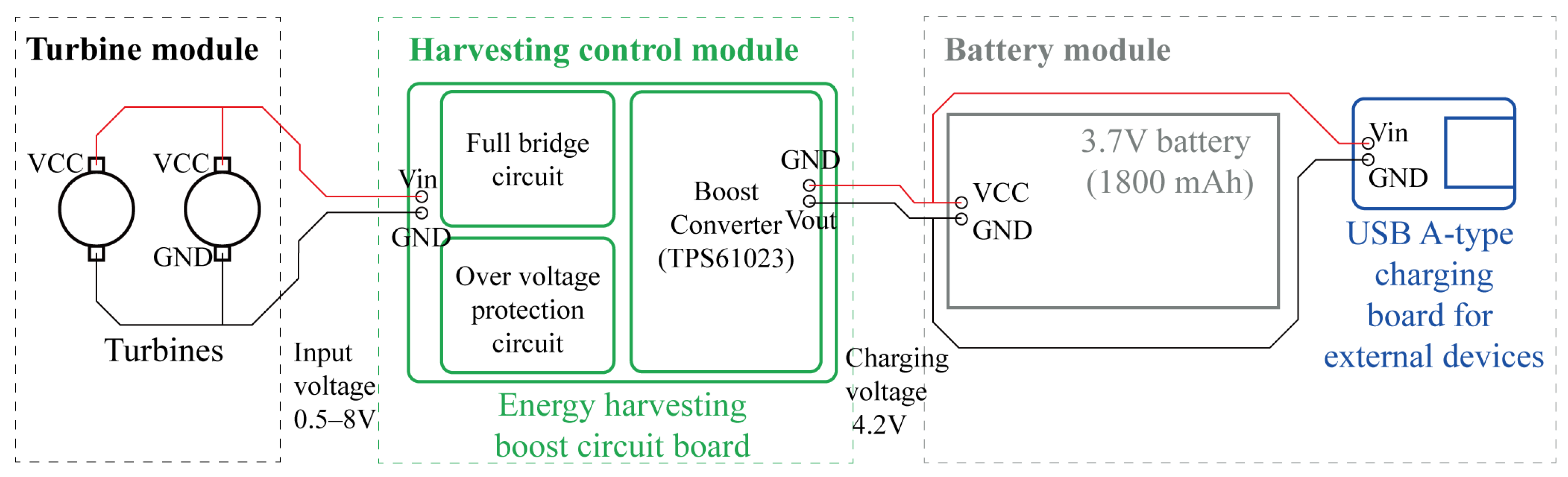
Using the above results as the design basis, the harvesting circuit was configured as a compact AC/DC–DC/DC energy-conditioning module for two side-mounted turbines. The overall electrical pathway was designed as follows: (1) turbine rotation generates low, speed-dependent electrical output; (2) the generated output is rectified by a full-bridge rectifier; (3) an input capacitor buffers short-term voltage fluctuation caused by intermittent airflow and rotor-speed variation; (4) a boost-converter stage raises the conditioned input to a battery-charging level; and (5) the regulated output is delivered to the rechargeable battery module. This architecture is consistent with prior small-scale wind energy-harvesting systems, where rectification, temporary buffering, voltage boosting, and storage management are essential because the raw turbine output is highly variable and cannot be used directly as a stable charging source (Figure 2).
The boost-conversion stage was implemented using the TPS61023 low-input-voltage boost converter (Texas Instruments, Dallas, TX, USA). According to the manufacturer’s datasheet, this device supports an input voltage range of 0.5–5.5 V, requires a minimum input voltage of 1.8 V for startup, and allows an output voltage setting range of 2.2–5.5 V. These characteristics made it suitable to the present application, in which turbine output during motion was low, fluctuating, and often near the lower boundary of practical battery-charging operation. In the present circuit, the converter was configured to deliver an output of approximately 4.28 V, corresponding to the upper end of the stable voltages reported in the second-stage circuit operation test.
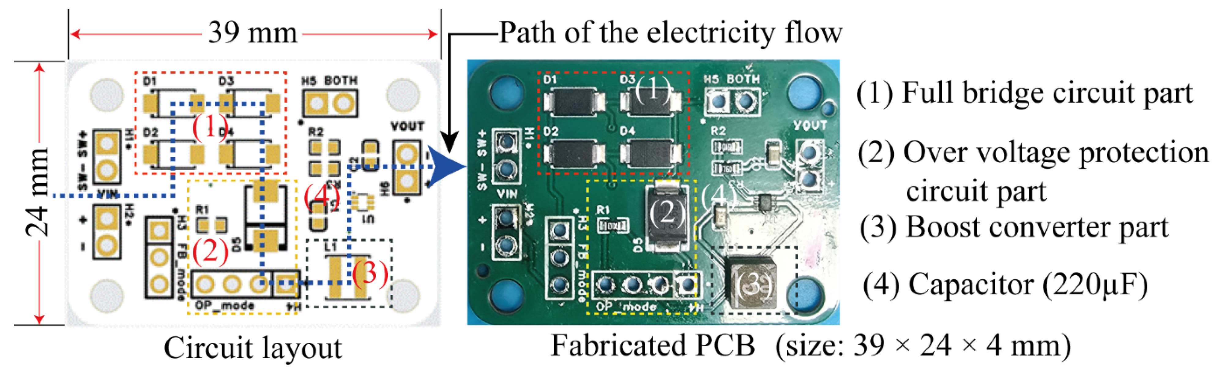
The PCB incorporated a full-bridge rectifier, reverse-current blocking and overvoltage protection elements, a boost converter stage, and an input capacitor. The board was fabricated in a compact 39 × 24 × 4 mm form factor for housing within the helmet-mounted harvesting module (Figure 3). Because turbine-driven input was intermittent and not continuously maintained at the converter startup threshold, an input capacitor was added to improve hold-up performance and suppress rapid input collapse during short-term speed fluctuation. Through developmental testing, a 220 μF capacitor was selected because it yielded more stable converter operation than lower-capacitance alternatives. The use of intermediate storage or buffering is widely adopted in energy-harvesting systems because harvested energy sources often provide low average power but highly transient instantaneous input.

3.2. Harvesting Components Integration on the Helmet Platform

A second experiment was conducted to determine the final turbine configuration to be integrated into the helmet prototype by evaluating the compatibility between the selected housing–rotor combinations and the developed harvesting boost circuit under vehicle-induced airflow. Based on the first-stage results, housing Hd was cross-combined with three candidate rotors (Ra, Rb, and Re), and the electrical behavior of the circuit-connected system was assessed at 30, 40, and 50 km/h. These speeds were selected because they corresponded to the practical operating range of the medium generator identified in Section 3.1. As in the first-stage tests, each speed condition was maintained for 10 s, and each housing–rotor–speed combination was tested three times. The voltage values reported in Table 7, therefore, represent the range observed across repeated measurements, while the “operation” column indicates whether the boost circuit reached and maintained stable operation during the corresponding trial interval. This second-stage evaluation was necessary because, once the turbine output was connected to the protection and boost-conversion circuitry, the rotor no longer operated under no-load conditions and could thus exhibit behavior different from that observed during the turbine-only screening test.
The second-stage test was designed not merely as another empirical comparison but as a validation step for the integrated electromechanical system. In compact harvesters, a rotor that performs well in open-circuit conditions may fail to sustain converter startup once rectification losses, reverse-current protection, and transient electrical loading are introduced. Accordingly, the present test compared not only measured voltage values but also the stability of circuit operation under the same airflow conditions. This distinction is consistent with prior low-power harvesting system studies, which emphasize that the practical utility of a harvester depends on whether the entire energy path—from generator output to storage-stage input—remains operational under real-world stimulation, rather than on raw generator voltage alone.
As shown in Table 7, the Hd–Rb combination exhibited the most stable overall behavior across the three test speeds. The Hd–Ra combination remained unstable at 30 km/h and stabilized only starting 40 km/h, whereas the Hd–Re combination did not provide stable operation until 50 km/h. By contrast, Hd–Rb operated stably from 30 km/h and maintained a regulated output level of approximately 4.28 V at higher speeds. These results indicate that the rotor with the highest no-load rotational performance was not necessarily the most effective once the harvesting circuit was connected. Rather, the comparatively lightweight, higher-blade-count pinwheel rotor Rb appears to have provided a more favorable balance between aerodynamic torque generation and the added electrical resistance imposed by the conditioning circuit.
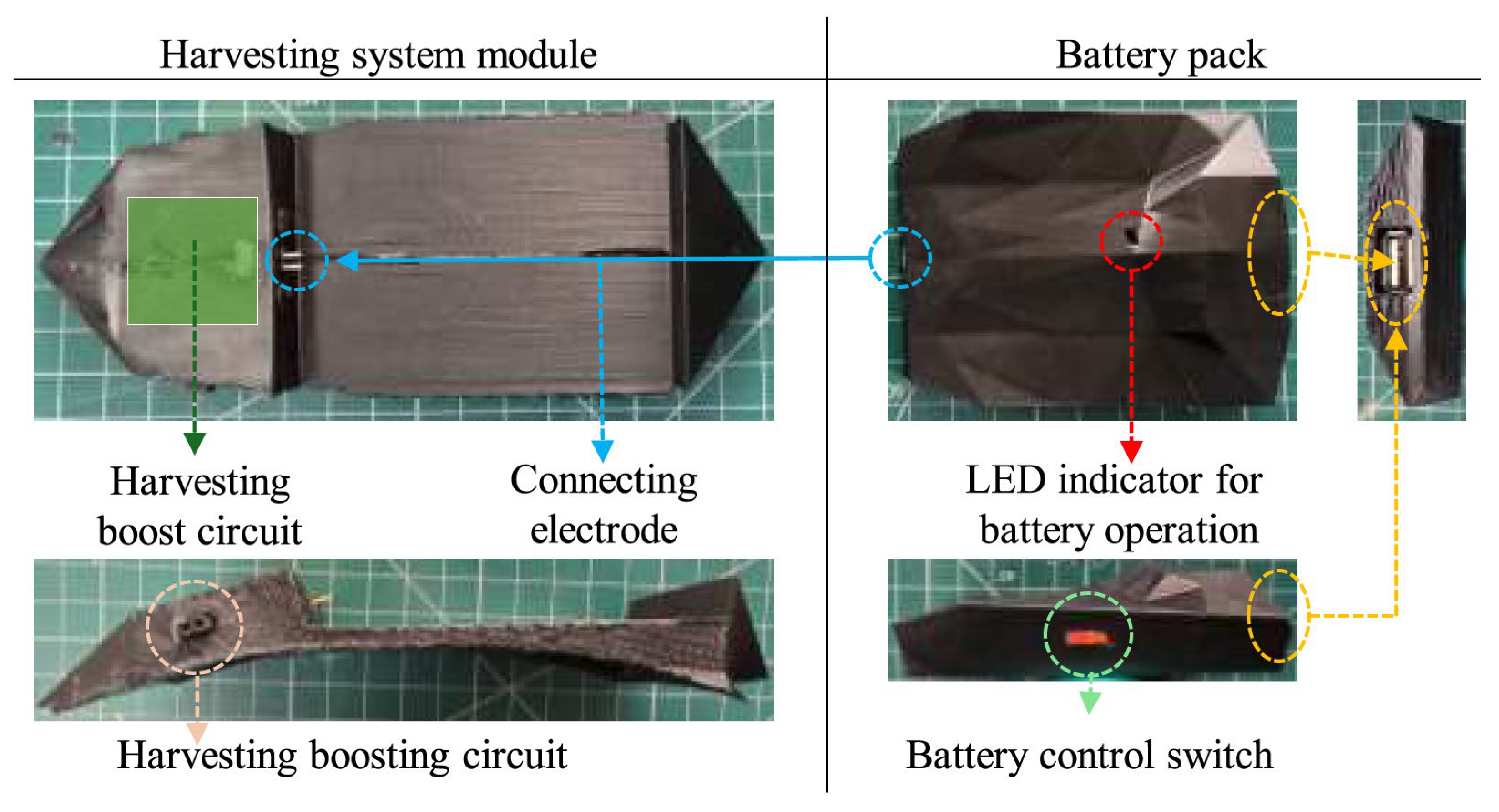
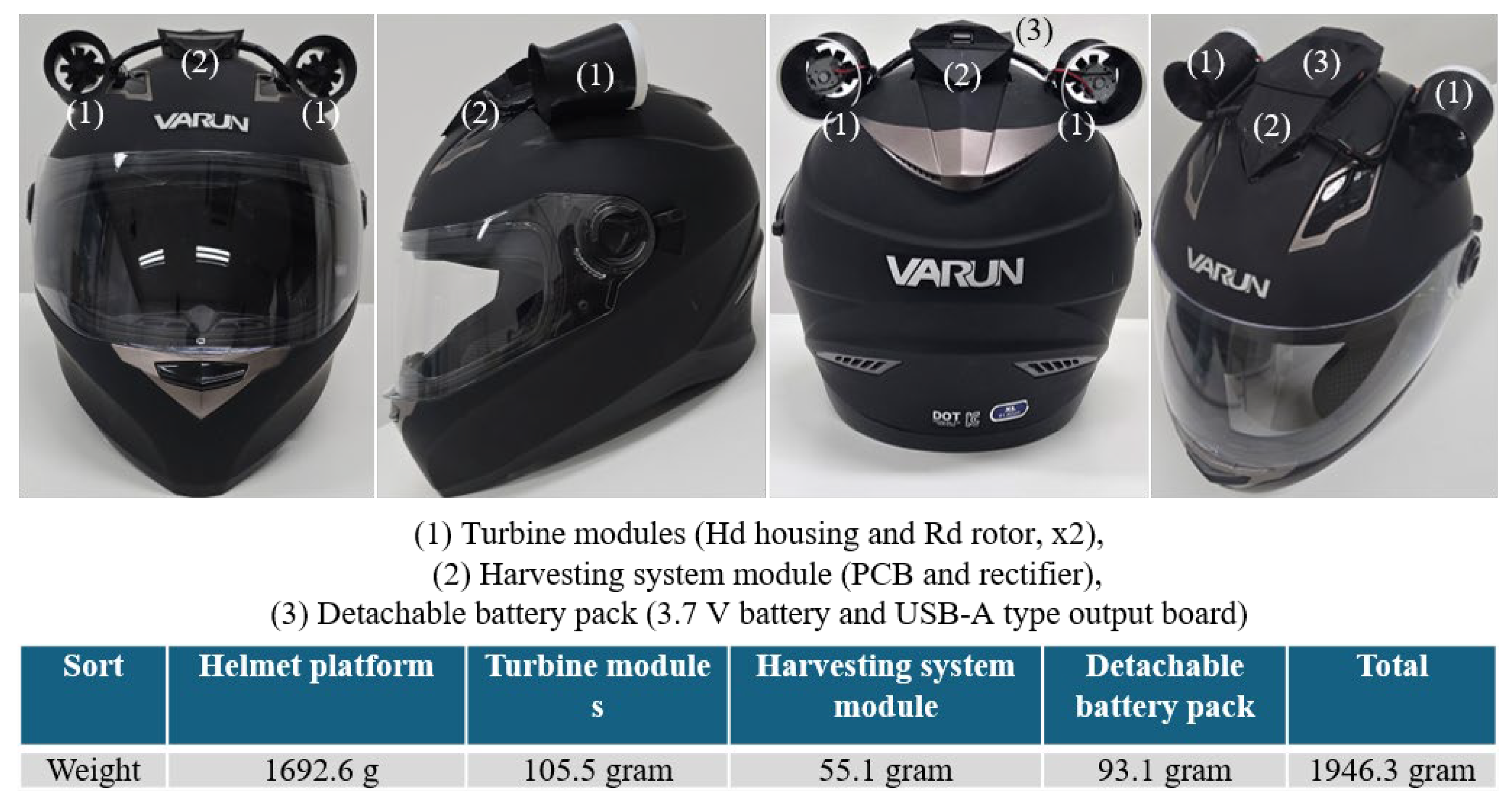
Accordingly, housing Hd and rotor Rb were selected for integration into the helmet prototype. The final system was arranged so that the harvesting-boost module and detachable battery pack were mounted at the helmet’s crown (bregma region), while the two turbine modules were positioned symmetrically on the left and right sides. This arrangement was adopted to minimize asymmetric mass distribution and to preserve the rider’s sense of balance as far as practicable. In practical use, electricity generated by the two turbines is rectified and boosted by the integrated PCB, then stored in the detachable rechargeable battery module. The battery pack includes a USB-A output module and a mode-selection switch, enabling the user either to store harvested energy during riding or to use the stored energy afterward for charging small external devices such as smartphones or accessory electronics (Figure 4). This harvesting–storage–use pathway aligns with the broader direction of wearable self-powered systems, which increasingly integrate energy capture, intermediate storage, and user-facing output functions within a single modular platform.
The harvesting system and battery housings were designed with a 2 mm thick outer wall to ensure baseline structural durability. The harvesting boost circuit and battery are interconnected via electrodes, and the assemblies are mechanically secured by neodymium magnets embedded within each housing. The battery pack integrates a USB-A charging module and a mode-selection switch; when the stored energy is to be utilized, the switch toggles the pack between harvesting or charging mode and external-device charging mode, enabling mobile device charging. To validate the data acquisition system used in the subsequent riding experiment, the INA219 voltage–current sensor board (Adafruit Industries, New York, NY, USA) was bench-calibrated prior to field deployment using a programmable DC power supply (accuracy ±0.1% of setting) at five reference levels spanning the expected operating range (0.5, 1.5, 3.0, 4.0, and 5.5 V). Measured values deviated from the reference by no more than ±0.5%, confirming sensor accuracy within the system’s operational range. This calibration procedure constitutes the data validation step for the electrical measurement subsystem.
To reduce protrusion and preserve the helmet’s streamlined silhouette, the crown-mounted housing was divided into a forward section that accommodates the harvesting boost circuit and electrode interface, and an aft section containing the detachable battery pack. The two sections were structurally and electrically connected via embedded electrodes and mechanically secured with neodymium magnets. This detachable architecture offers two practical advantages. First, the battery can be removed independently for charging or replacement without disassembling the turbine housing. Second, the modular arrangement may support future redesign toward safer break-away or deformable interfaces if impact-safety optimization is pursued. From a cost perspective, however, this modularity also increases component count by requiring separate housings, magnets, electrode interfaces, and a detachable charging pack. Therefore, while the present design improves functional usability, it is also expected to increase the final product price relative to a standard full-face helmet. Because the exact cost would depend on manufacturing scale, component sourcing, and housing fabrication method, the current study discusses cost impact qualitatively rather than as a finalized commercial estimate.
The system housings were fabricated using a BambuLab X1-Carbon 3D printer (Bambu Lab, Shenzhen, China) with carbon fiber-reinforced PLA (PLA-CF) filament, as the externally mounted parts required sufficient stiffness and dimensional stability for prototype evaluation. However, the use of a relatively stiff printed polymer should be interpreted only as a practical prototyping choice, not as evidence of crashworthiness. In the current proof-of-concept stage, PLA-CF was useful for producing geometrically stable modules and rapidly iterating housing designs, but future safety-oriented versions should consider materials and attachment interfaces that better reconcile structural integrity during use with reduced injury risk under impact.
The total weight of the developed prototype was 1946.3 g, with the bulk of the weight attributable to the full-face helmet used for development, which accounted for 1692.6 g. The additional components, including the harvesting boost circuit, the battery pack, and two turbine modules, weighed 253.7 g (Figure 5). Considering the snug fit of motorcycle helmets, the additional 253.7 g is not expected to significantly impede user head movement. This assessment is supported by prior research demonstrating that for head-mounted equipment, comfortable wear time decreases by approximately 11 min for every 33 g increase in weight in the lower quartile of users [43]; the 253.7 g increment added by the harvesting system represents approximately a 15% increase over a typical full-face helmet baseline, which falls within ranges documented as tolerable for task-oriented use in head-mounted device studies.

4. Results and Discussion

4.1. Wearability Evaluation

A wearability assessment was conducted to examine whether the additional harvesting components mounted on the helmet adversely affected basic fit, perceived balance, or head-movement comfort during simulated riding posture. As shown in the current manuscript, six adult participants who either owned a motorcycle or had more than one year of riding experience were recruited for this evaluation, and the test was performed with the participants seated on a stationary motorcycle while wearing the developed prototype. The assessment protocol included a standardized sequence of head and neck movements consisting of neutral posture, left rotation, right rotation, rearward observation, neck flexion, and neck extension, followed by a questionnaire-based comfort evaluation and qualitative interview. The questionnaire used a five-point Likert scale, where 1 indicated “very uncomfortable,” and 5 indicated “very comfortable” (Table 8).
As summarized in Table 8, all five questionnaire items yielded an average score of 5.0, indicating that the participants did not report obvious discomfort related to static wearability, perceived mass distribution, or the range of head movement under the tested condition. In the follow-up interview, participants likewise reported that the prototype remained securely fitted and that no substantial inconvenience was perceived during the prescribed motion sequence. Within the limited scope of this stationary assessment, these results suggest that the additional system mass of 253.7 g did not produce an immediately detectable deterioration in basic helmet fit or static head-movement comfort.
However, this result must be interpreted with caution. Because the wearability assessment was conducted on a stationary motorcycle, it did not replicate the aerodynamic drag, wind noise, dynamic vibration, or posture stabilization demands encountered during actual riding. Therefore, a score of 5 in the present test should be interpreted only as evidence of static wearability under a quasi-riding posture and may not be as proof that the prototype maintains the same level of comfort or mobility when exposed to real airflow at 30–50 km/h. This constitutes a methodological limitation: the wearability evaluation does not capture the increased neck muscle effort or comfort decrement that riders may experience at speed due to the added aerodynamic load of the external turbine modules. Dynamic wearability testing, in which participants perform the same head-movement protocol while the vehicle is in motion at target speeds, is explicitly identified as a priority objective for future work.
Participants evaluated the prototype’s wearability positively, reporting that the helmet fitted their heads securely and stably, and that the prescribed test movements could be performed while maintaining a motorcycle riding posture without discomfort related to the prototype’s mass distribution. These findings suggest that, under the applied static test conditions, the additional weight of the harvesting-system components (253.7 g) did not adversely affect helmet wearability or head movement.
To complement the subjective evaluation, inter-rater consistency across the five Likert-scale items was examined. All six participants assigned the maximum score of 5 to every item, resulting in no variance across either items or participants. This unanimous response provides evidence that the added weight did not produce perceptible discomfort under static conditions. However, the absence of score variability also suggests that dynamic testing conditions may be necessary, as aerodynamic loads during actual riding could reveal comfort differences that were not captured in the static assessment. Such testing is therefore proposed as an important direction for future follow-up research [43,44].

4.2. Riding Experiment and Power-Generation Performance

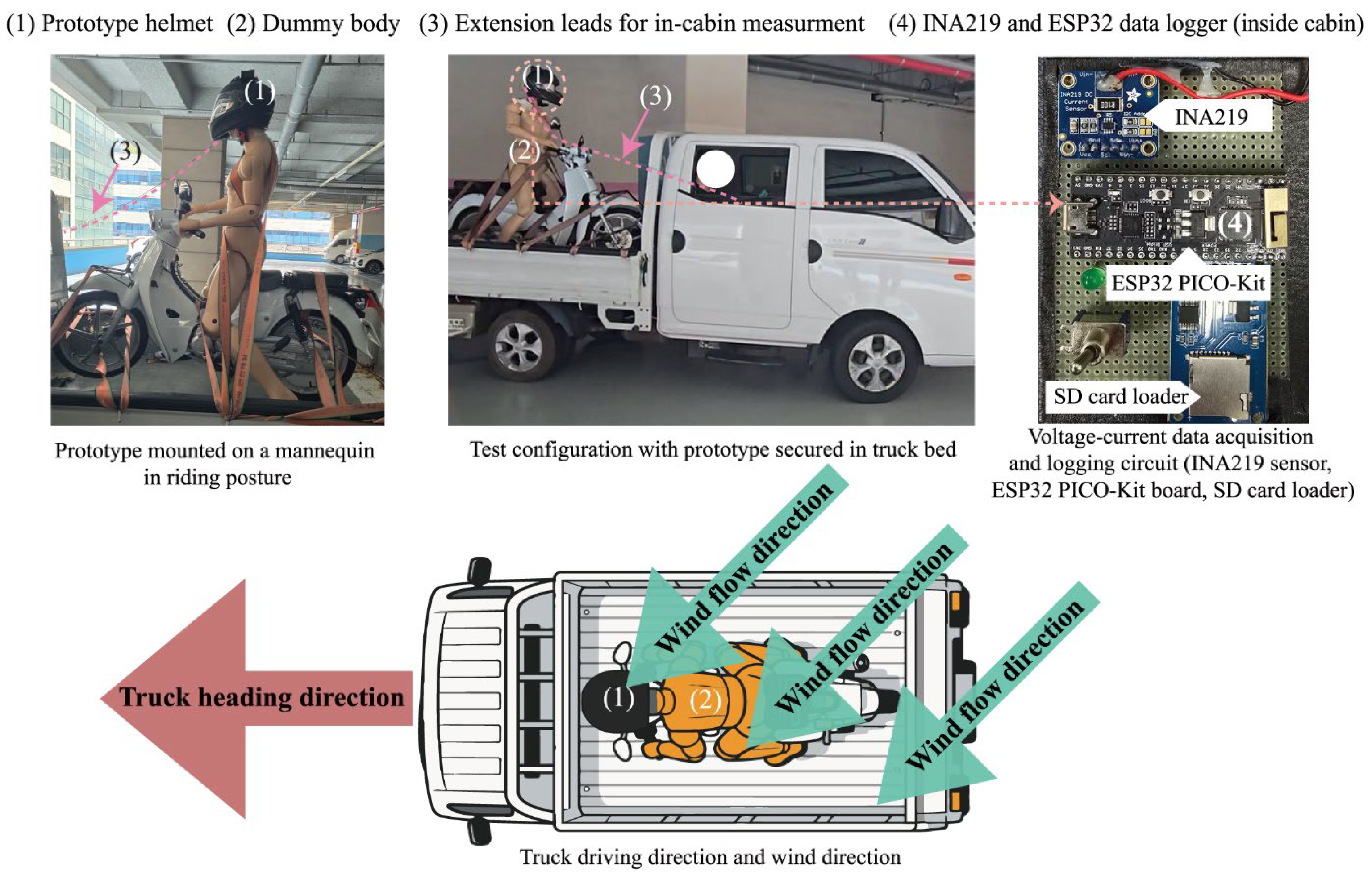
Given the requirement for high-speed operation, the power generation efficiency test for the developed wind energy harvesting system was conducted using an alternative setup similar to that employed during the development phase. The prototype was first mounted on a dummy body in a motorcycle riding posture and then rigidly secured to the truck’s cargo bed. A voltage–current data acquisition and logging circuit was designed and employed to characterize system behavior in greater detail during motion. This measurement module consisted of an Adafruit INA219 voltage-current sensor board, an SD card module for data storage, and an ESP32-PICO-Kit microcontroller board (Espressif Systems Co., Ltd., Shanghai, China) to govern device operation. Before use, the sensors were calibrated with a programmable bench power supply capable of controlling output voltage and current at five reference levels (0.5, 1.5, 3.0, 4.0, and 5.5 V), confirming measurement accuracy within ±0.5% across the operational range.
The riding experiment was repeated thrice at each speed level (30, 40, and 50 km/h), with each run lasting 10 s. The average values reported in Table 9 represent the mean across all sampled data points from all three runs at each speed level, and the power-generation pattern graphs display the instantaneous time series from a representative run. The logging firmware was configured to sample at a rate of four times Hz (250 ms intervals) and write the measured power data to the SD card (Figure 6).
The outdoor test was performed on a clear day with an ambient northwesterly wind of approximately 3 m/s. The direction of ambient wind was approximately aligned with the direction of travel (within ±20° of the heading axis), such that the ambient wind contributed constructively to the axial airflow incident on the turbine inlets, augmenting the vehicle-speed component of the relative wind by approximately 3 m/s. It should be noted that, because this experiment was conducted outdoors rather than in a wind tunnel, the influence of inflow-angle variation caused by ambient wind could not be completely eliminated. The riding experiment was conducted on a straight, low-traffic suburban roadway for safety. Following the development-phase protocol, the vehicle was driven for 10 s at each of the 30, 40, and 50 km/h speed levels, with three repetitions per speed level. The measurement and logging circuit recorded the system’s voltage and current at 250 ms intervals throughout each run. After the run, the stored data were processed statistically.
Table 9 reports, for each speed level, the mean generated voltage, current, and power (with SD) computed from all data points across the three repeated runs, as well as the temporal trends in instantaneous power generation observed during a representative run at each speed.
Examination of the experimental data reveals that transient fluctuations in output voltage were observed at each test speed; however, time-averaged values confirmed that the system generated sufficient electricity to charge a standard 3.7 V battery commonly used in mobile devices. Based on data sampled at 250 ms intervals, instantaneous power fluctuations were observed over each riding period because of minor variations in vehicle speed and ambient wind gusts; nevertheless, the time-averaged output maintained a voltage level sufficient for battery charging at all three test speeds. As shown in Table 9 and in the time-series power-generation plots, the developed system exhibited a consistent increase in mean voltage, current, and power as vehicle speed increased from 30 to 50 km/h. The mean power rose from 157.64 mW at 30 km/h to 192.61 mW at 40 km/h and 291.73 mW at 50 km/h, indicating that the system responded positively to stronger relative airflow. This overall trend is physically reasonable because the power available in wind increases strongly with wind speed, even though compact real systems often deviate from idealized scaling because of startup losses, flow misalignment, turbulence, and electrical conditioning losses.
The power-generation pattern plots show that the prototype exhibited transient output fluctuations around a stable, speed-dependent mean level. The system did not generate perfectly constant power during motion; instead, it produced a fluctuating signal whose mean level increased with speed—behavior consistent with that expected of small wind energy systems exposed to nonuniform real-world airflow. Accordingly, the key result is not the absence of fluctuation, but the maintenance of a practically useful mean charging-level output despite that fluctuation.
The experiment was conducted under field conditions rather than in a fully controlled aerodynamic environment, and the observed fluctuations are likely to reflect not only actual variations in turbine rotational speed but also the combined effects of local inflow-angle changes, vehicle vibration, and ambient wind. Therefore, the values presented in Table 9 should be interpreted not as laboratory constants, but as field-performance measurements obtained under outdoor operating conditions.
The somewhat lower voltage observed at 30 km/h, relative to earlier preliminary tests, can be interpreted in this context. The discrepancy is likely attributable to the combined effect of outdoor environmental variability, the mannequin-based mounting configuration, and differences in helmet pitch or yaw relative to the incoming flow. Because small turbines are sensitive to inflow angle and local velocity distribution, even modest changes in posture or ambient wind alignment can influence measured output. Therefore, the 30 km/h result should not be interpreted as contradictory to the development-stage screening findings, but rather as evidence that field-mounted wearable harvesters are sensitive to real-world operating conditions.
Despite these limitations, the system was confirmed to generate a practically useful level of electrical output for battery charging at all three test speeds. This finding indicates that the helmet-integrated microturbine system can produce continuous milliwatt-scale power output from vehicle-induced aerodynamic flow. The achieved power level (time-averaged 157–292 mW) is substantially higher than that reported for wearable piezoelectric and thermoelectric harvesters, which typically generate 1–500 µW, and is comparable to the lower range of wearable solar-energy harvesting systems under outdoor conditions [15,16]. Therefore, the primary objective of the present study may be considered substantially achieved.
However, it should be noted that motorcycle helmets are highly regulated safety devices, and any modification to the helmet shell, particularly the attachment of rigid external components, must be carefully considered in terms of crash safety. While the present study represents a proof-of-concept prototype, future design iterations should pursue integration strategies that allow turbine modules to detach or yield upon impact, in compliance with relevant safety standards. A dedicated safety analysis of the proposed mounting system is acknowledged as a critical direction for subsequent work.
In addition, the acoustic implications of mounting a rotating turbine near the rider’s ear should be explicitly acknowledged. Aerodynamic noise and mechanical vibration generated by high-speed rotating components may increase the sound pressure level at the ear position and, if not properly addressed, could contribute to rider fatigue or long-term hearing damage [45]. Although a preliminary noise assessment was not within the scope of the present prototype evaluation, acoustic characterization, including sound pressure level measurements and comparisons with occupational noise exposure criteria, is intended to be examined in future follow-up research.

5. Conclusions

This study investigated the feasibility of a wearable turbine-based energy-harvesting system integrated into a motorcycle helmet, aiming to convert aerodynamic flow generated by riding into storable electrical energy. Rather than proposing a new physical principle of wind energy conversion, the study addressed an application-specific design problem: whether a compact horizontal-axis turbine system, together with a boost-conversion and storage module, could be configured in a wearable helmet platform and produce electrically useful output under riding-relevant airflow conditions. Through staged experiments, a medium-scale generator, a diffuser-type housing (Hd), and an eight-blade pinwheel rotor (Rb) were identified as the most suitable combination for the developed prototype.
The final prototype integrated two turbine modules, a harvesting-boost circuit, and a detachable battery module into a full-face helmet platform. The system was designed so that electricity generated during riding could be rectified, boosted, and stored in the onboard battery pack. The stored energy could later be used via a USB-A output to charge small external devices. In the driving experiment, the prototype generated mean outputs of 3.99 V/39.51 mA/157.64 mW at 30 km/h, 4.43 V/43.48 mA/192.61 mW at 40 km/h, and 5.45 V/53.53 mA/291.73 mW at 50 km/h, indicating that the average electrical output increased with vehicle speed and reached a level relevant to charging a conventional 3.7 V battery. These findings support the practical feasibility of the proposed concept as an auxiliary wearable power source under field conditions.
At the same time, the present findings should be interpreted within the actual boundaries of the experiment. The measured output was not perfectly constant during motion; instead, the system exhibited transient fluctuations around a speed-dependent average level. Moreover, the riding experiment was conducted in an outdoor field configuration using a mannequin with a helmet mounted on a truck bed, rather than in fully controlled aerodynamic laboratory conditions. Accordingly, the reported electrical values should be understood as field-performance evidence of practical charging feasibility, not as universal performance constants for wearable wind harvesters.
Similarly, the wearability evaluation confirmed that the prototype could be worn without obvious discomfort under a stationary quasi-riding posture; however, this assessment did not include the aerodynamic drag, vibration, and posture-stabilization demands encountered during actual riding. Therefore, the current wearability result should be regarded as a preliminary static usability finding rather than definitive proof of dynamic riding comfort.
In addition, the present prototype should not be interpreted as a finalized safety-certified product. Because the turbine modules and crown-mounted housings were externally attached and fabricated from relatively stiff materials, future studies must more rigorously address crash safety, potential snag or rotational loading during impact, and the acoustic burden caused by two rotating turbines near the rider’s ears. Likewise, while the added mass and modular battery architecture were acceptable for proof-of-concept evaluation, issues of cost, manufacturability, and user acceptance must also be examined before practical commercialization. These aspects are not peripheral concerns but central design requirements for any wearable energy-harvesting system intended for real motorcycle use.
Future work should therefore proceed in four directions. First, controlled wind-tunnel or equivalent aerodynamic experiments are needed to validate performance under known inflow conditions and to quantify the influence of ambient wind direction, turbulence, and helmet orientation. Second, mathematical and/or computational modeling should be developed to relate airflow, rotor behavior, circuit loading, and charging performance in a physically interpretable framework. Third, dynamic wearability and acoustic tests should be performed with either instrumented head forms or safely supervised riding trials. Fourth, a design iteration toward lower-profile, deformable, or break-away integration structures is needed to reconcile energy-harvesting functionality with helmet safety requirements.
Despite these limits and prospects, this study provides foundational design data and proof-of-concept evidence for the development of wearable wind energy-harvesting systems applicable not only to motorcycle helmets but also to bicycles, personal mobility platforms, and other wind-exposed wearable protective equipment.

Author Contributions

Conceptualization, H.L.; methodology, H.L.; software, H.L.; validation, H.L.; formal analysis, Y.K. and H.L.; investigation, Y.K. and H.L.; resources, H.L.; data curation, Y.K. and H.L.; writing—original draft preparation, H.L.; writing—review and editing, Y.K. and H.L.; visualization, H.L.; supervision, H.L.; project administration, H.L.; funding acquisition, H.L. All authors have read and agreed to the published version of the manuscript.

Funding

This research was funded by Incheon National University, grant number 2021-0150.

Institutional Review Board Statement

The study was conducted in accordance with the Declaration of Helsinki. The human-subject wearability evaluation of the helmet in this study was conducted with approval from the Institutional Review Board (IRB) of Semyung University (IRB approval No. SMU-2025-08-001-02, accepted date: 18 September 2025).

Informed Consent Statement

Informed consent was obtained from all subjects involved in the study. As this study does not include any information that could identify individual participants, written informed consent for publication is not applicable.

Data Availability Statement

The data used and generated in this study are available from the corresponding author upon reasonable request. However, some materials related to the human-subject evaluation may be restricted from public disclosure due to privacy considerations and the conditions of the Institutional Review Board (IRB) approval.

Acknowledgments

The authors would like to thank Ji-chan Lee for his contribution to the experimental design and Seok-jin Oh for his helpful advise on the harvesting system design in this study.

Conflicts of Interest

The authors declare no conflicts of interest.

Abbreviations

The following abbreviations are used in this manuscript:
HAWTHorizontal-Axis Wind Turbine
PCBPrinted Circuit Board
PLAPolylactic Acid
PLA-CFCarbon Fiber-Reinforced PLA
USB-AUniversal Serial Bus Type-A
VAWTVertical-Axis Wind Turbine

References

  1. Ali, A.; Shaukat, H.; Bibi, S.; Altabey, W.A.; Noori, M.; Kouritem, S.A. Recent progress in energy harvesting systems for wearable technology. Energy Strateg. Rev. 2023, 50, 101124. [Google Scholar] [CrossRef]
  2. Yin, L.; Wang, J. Wearable energy systems: What are the limits and limitations? Natl. Sci. Rev. 2022, 10, nwac060. [Google Scholar] [CrossRef] [PubMed]
  3. Kang, M.; Yeo, W.-H. Advances in energy harvesting technologies for wearable devices. Micromachines 2024, 15, 884. [Google Scholar] [CrossRef] [PubMed]
  4. Wang, H.; Xiong, B.; Zhang, Z.; Zhang, H.; Azam, A. Small wind turbines and their potential for internet of things applications. iScience 2023, 26, 107674. [Google Scholar] [CrossRef]
  5. Lee, S.Y.; Park, J.T. Analysis on factors contributing to motorcycle accidents of food delivery riders. J. Korean Soc. Saf. 2022, 37, 70–77. [Google Scholar] [CrossRef]
  6. Wang, P.; Liu, Y.; Zhu, R.; Qin, L.; Deng, J.; Yang, Z.; Qin, Z.; Chu, F. Dynamic analysis of vibro-impact energy harvester with acoustic black hole. Int. J. Mech. Sci. 2025, 291–292, 110193. [Google Scholar] [CrossRef]
  7. Ebaid, M.S.Y.; Shahin, Z.A.A.E.; Alshawabkeh, M.M.D. Feasibility studies of micro wind turbines installed on electric vehicles as range extenders using real-time analytical simulation with multi driving cycles scenarios. Adv. Mech. Eng. 2023, 15, 16878132231165964. [Google Scholar] [CrossRef]
  8. Kim, K.A.; Bagci, F.S.; Dorsey, K.L. Design considerations for photovoltaic energy harvesting in wearable devices. Sci. Rep. 2022, 12, 18143. [Google Scholar] [CrossRef]
  9. Páez-Montoro, A.; García-Valderas, M.; Olías-Ruíz, E.; López-Ongil, C. Solar energy harvesting to improve capabilities of wearable devices. Sensors 2022, 22, 3950. [Google Scholar] [CrossRef]
  10. Hossain, I.Z.; Khan, A.; Hossain, G. A piezoelectric smart textile for energy harvesting and wearable self-powered sensors. Energies 2022, 15, 5541. [Google Scholar] [CrossRef]
  11. Tohidinejad, Z.; Danyali, S.; Valizadeh, M.; Seepold, R.; TaheriNejad, N.; Haghi, M. Designing a hybrid energy-efficient harvesting system for head- or wrist-worn healthcare wearable devices. Sensors 2024, 24, 5219. [Google Scholar] [CrossRef]
  12. Swallow, L.M.; Luo, J.K.; Siores, E.; Patel, I.; Dodds, D. A piezoelectric fibre composite based energy harvesting device for potential wearable applications. Smart Mater. Struct. 2008, 17, 025017. [Google Scholar] [CrossRef]
  13. Yuce, M.; Hamid, R.; Mohammadi, A. WE-Harvest: A wearable piezoelectric-electromagnetic energy harvester. EAI Endorsed Trans. Internet Things 2016, 2, 62–66. [Google Scholar] [CrossRef]
  14. Wu, S.; Luk, P.C.K.; Li, C.; Zhao, X.; Jiao, Z.; Shang, Y. An electromagnetic wearable 3-DoF resonance human body motion energy harvester using ferrofluid as a lubricant. Appl. Energy 2017, 197, 364–374. [Google Scholar] [CrossRef]
  15. Brogan, Q.; O’Connor, T.; Ha, D.S. Solar and thermal energy harvesting with a wearable jacket. In Proceedings of the 2014 IEEE International Symposium on Circuits and Systems (ISCAS), Melbourne, VIC, Australia, 1–5 June 2014; pp. 1412–1415. [Google Scholar] [CrossRef]
  16. Jokic, P.; Magno, M. Powering smart wearable systems with flexible solar energy harvesting. In Proceedings of the 2017 IEEE International Symposium on Circuits and Systems (ISCAS), Baltimore, MD, USA, 28–31 May 2017; pp. 1–4. [Google Scholar] [CrossRef]
  17. Yang, Y.; Pradel, K.C.; Jing, Q.; Wu, J.M.; Zhang, F.; Zhou, Y.; Zhang, Y.; Wang, Z.L. Thermoelectric nanogenerators based on single Sb-doped ZnO micro/nanobelts. ACS Nano 2012, 6, 6984–6989. [Google Scholar] [CrossRef] [PubMed]
  18. Kumar, R.; Raahemifar, K.; Fung, A.S. A critical review of vertical axis wind turbines for urban applications. Renew. Sustain. Energy Rev. 2018, 89, 281–291. [Google Scholar] [CrossRef]
  19. Fazylova, A.; Alipbayev, K.; Aden, A.; Oraz, F.; Iliev, T.; Stoyanov, I. A comparative review of vertical axis wind turbine designs: Savonius rotor vs. Darrieus rotor. Inventions 2025, 10, 95. [Google Scholar] [CrossRef]
  20. Johari, M.K.; Jalil, M.A.A.; Shariff, M.F.M. Comparison of horizontal axis wind turbine (HAWT) and vertical axis wind turbine (VAWT). Int. J. Eng. Technol. 2018, 7, 74–80. [Google Scholar] [CrossRef]
  21. Nawar, M.A.A.; Hameed, H.S.A.; Ramadan, A.; Attai, Y.A.; Mohamed, M.H. Experimental and numerical investigations of the blade design effect on Archimedes spiral wind turbine performance. Energy 2021, 233, 120051. [Google Scholar] [CrossRef]
  22. Saad, M.M.M.; Asmuin, N. Comparison of horizontal axis wind turbines and vertical axis wind turbines. IOSR J. Eng. 2014, 4, 27–30. [Google Scholar] [CrossRef]
  23. Shires, A.; Kourkoulis, V. Application of circulation controlled blades for vertical axis wind turbines. Energies 2013, 6, 3744–3763. [Google Scholar] [CrossRef]
  24. Kassa, B.Y.; Baheta, A.T.; Beyene, A. Current trends and innovations in enhancing the aerodynamic performance of small-scale, horizontal axis wind turbines: A review. ASME Open J. Eng. 2024, 3, 031001. [Google Scholar] [CrossRef]
  25. Eriksson, S.; Bernhoff, H.; Leijon, M. Evaluation of different turbine concepts for wind power. Renew. Sustain. Energy Rev. 2008, 12, 1419–1434. [Google Scholar] [CrossRef]
  26. Sutherland, H.J.; Berg, D.E.; Ashwill, T.D. A Retrospective of VAWT Technology. Available online: https://www.osti.gov/servlets/purl/1035336 (accessed on 10 September 2025).
  27. Toja-Silva, F.; Colmenar-Santos, A.; Castro-Gil, M. Urban wind energy exploitation systems: Behaviour under multidirectional flow conditions—Opportunities and challenges. Renew. Sustain. Energy Rev. 2013, 24, 364–378. [Google Scholar] [CrossRef]
  28. Jaszczur, M.; Borowski, M.; Halibart, J.; Zwolińska-Gladys, K.; Marczak, P. Optimization of the small wind turbine design—Performance analysis. Computation 2024, 12, 215. [Google Scholar] [CrossRef]
  29. Budanko, M.; Guzović, Z. Design methodology and economic impact of small-scale HAWT systems for urban distributed energy generation. Machines 2024, 12, 886. [Google Scholar] [CrossRef]
  30. Corbalán, P.A.; Chiang, L.E. Fast power coefficient vs. tip–speed ratio curves for small wind turbines with single-variable measurements following a single test run. Energies 2024, 17, 1199. [Google Scholar] [CrossRef]
  31. Calautit, K.; Johnstone, C. State-of-the-art review of micro to small-scale wind energy for building integration. Energy Conv. Manag. X 2023, 20, 10047. [Google Scholar] [CrossRef]
  32. Ohya, Y.; Karasudani, T. A shrouded wind turbine generating high output power with wind-lens technology. Energies 2010, 3, 634–649. [Google Scholar] [CrossRef]
  33. Bourhis, M.; Pereira, M.; Ravelet, F.; Dobrev, I. Innovative design method and experimental investigation of a small-scale and very low tip-speed ratio wind turbine. Exp. Therm. Fluid Sci. 2022, 130, 110504. [Google Scholar] [CrossRef]
  34. Ohya, Y.; Karasudani, T.; Sakurai, A.; Abe, K.-I.; Inoue, M. Development of a shrouded wind turbine with a flanged diffuser. J. Wind Eng. Ind. Aerodyn. 2008, 96, 524–539. [Google Scholar] [CrossRef]
  35. Jauhar, T.A.; Hussain, M.I.; Kiren, T.; Arif, W.; Miran, S.; Lee, G.H. Effect of flanged diffuser divergence angle on wind turbine: A numerical investigation. PLoS ONE 2023, 18, e0287053. [Google Scholar] [CrossRef] [PubMed]
  36. Kim, B.; Park, S.-J.; Ahn, S.; Kim, M.-G.; Yang, H.-G.; Ji, H.-S. Numerically and experimentally verified design of a small wind turbine with injection molded blade. Processes 2021, 9, 776. [Google Scholar] [CrossRef]
  37. Pan, H.-G.; Heng, W.; Feng, Z.-X.; He, M.-M. Design of air turbine flow passage and analysis of energy efficiency. Energy Procedia 2012, 17, 1217–1223. [Google Scholar] [CrossRef][Green Version]
  38. Bontempo, R.; Manna, M. Effects of the duct thrust on the performance of ducted wind turbines. Energy 2016, 99, 274–287. [Google Scholar] [CrossRef]
  39. Kumar, N.M.; Subathra, M.S.P.; Cota, O.D. Design and wind tunnel testing of funnel based wind energy harvesting system. Procedia Technol. 2015, 21, 33–40. [Google Scholar] [CrossRef]
  40. Howey, D.A.; Bansal, A.; Holmes, A.S. Design and performance of a centimeter-scale shrouded wind turbine for energy harvesting. Smart Mater. Struct. 2011, 20, 085021. [Google Scholar] [CrossRef]
  41. Li, Q.; Maeda, T.; Kamada, Y.; Murata, J.; Shimizu, K.; Ogasawara, T.; Nakai, A.; Kasuya, T. Effect of solidity on aerodynamic forces around straight-bladed vertical axis wind turbine by wind tunnel experiments (depending on number of blades). Renew. Energy 2016, 96, 928–939. [Google Scholar] [CrossRef]
  42. Yilmaz, O. Increasing power coefficient of small wind turbine over a wide tip speed range by determining proper design tip speed ratio and number of blades. Proc. Inst. Mech. Eng. Part C J. Mech. Eng. Sci. 2022, 236, 10045–10060. [Google Scholar] [CrossRef]
  43. Odell, D.; Dorbala, N. The effects of head mounted weight on comfort for helmets and headsets, with a definition of “comfortable wear time”. Work 2024, 77, 651–658. [Google Scholar] [CrossRef]
  44. Knight, J.F.; Baber, C. A tool to assess the comfort of wearable computers. Hum. Factors 2005, 47, 77–91. [Google Scholar] [CrossRef]
  45. Kennedy, J.; Carley, M.; Walker, I.; Holt, N. On-road and wind-tunnel measurement of motorcycle helmet noise. J. Acoust. Soc. Am. 2013, 134, 2004–2010. [Google Scholar] [CrossRef]
Figure 1. Configuration of the wearable wind energy harvesting system integrated into a motorcycle helmet.
Applsci 16 03482 g001
Figure 2. The device connection diagram for the wearable turbine energy harvesting system.
Applsci 16 03482 g002
Figure 3. Layout of the harvesting boost circuit and fabricated PCB (39 × 24 × 4 mm).
Applsci 16 03482 g003
Figure 4. The housing design of the harvesting system.
Applsci 16 03482 g004
Figure 5. The integrated energy harvesting systems on the helmet platform and the weight information.
Applsci 16 03482 g005
Figure 6. Prototype energy harvesting performance test setup: helmet mounted on a dummy body in motorcycle riding posture, rigidly secured to the truck cargo bed. This setup was adopted as a safety-conscious alternative to on-motorcycle testing at speeds up to 50 km/h. Ambient wind speed: 3 m/s (near-headwind, ±20° of travel heading).
Applsci 16 03482 g006
Table 1. Previous studies on wearable energy harvesting systems.
CaseApplied PlatformApplied TechnologiesEnergy Source and Usage ScenarioGenerated Electricity
Swallow et al. [12]GlovesPiezoelectric fiber compositePressure generated during graspingMaximum output 11 μW
Yang et al. [17]WristbandThermoelectric materialTemperature difference between skin and environmentCurrent 194 nA
Brogan et al. [15]JacketSolar cells + thermoelectric modulesSolar energy and body–environment temperature gradientMaximum output 500 mW (solar), 1.25 μW (thermoelectric)
Yuce et al. [13]JacketMagnets + piezoelectric elementsPressure generated during button fasteningCombined output 45 μW
Jokic and Magno [16]WristbandFlexible solar cellsSolar energyMaximum output 16 mW (outdoor), 0.21 mW (indoor)
Wu et al. [14]ShoesElectromagnetic mechanismWalking/running pressure and motionMaximum output 1.1 mW (walking), 2.28 mW (running)
Kim et al. [8]Forearm sleeveFlexible photovoltaic panelsSolar energy during outdoor arm-worn useUp to 93.9 mW outdoors; average 65 mW across tested arm positions
Páez-Montoro et al. [9]Smart braceletSemiflexible solar harvesterSolar energy during routine wearable use27.8–159.1 mW in real-life scenarios
Hossain et al. [10]Smart textile/clothing/insolePiezoelectric textile sensor (PVDF-based)Tapping, breathing, walking, raindrop impactMaximum power density 0.006 mW from a 24 cm2 sensor; rectified output up to 10 V
Tohidinejad et al. [11]Head- or wrist-worn wearablePhotovoltaic and thermoelectric harvesting systemOutdoor light and body heat for healthcare sensingSupported a 34 mW load; harvested energy stored in a 3.7 V, 300 mAh battery
Table 2. Categories of the wind power generation methodology.
TypeOperational FeatureBenefitDrawback
HAWTBlades oriented parallel to the groundHigher conversion efficiency than VAWTs
Not subject to the backtracking effect
Power generation ceases (or is severely diminished) when the wind direction is misaligned with the rotor/blade orientation
Unsuitable for highly turbulent flow conditions
VAWTBlades oriented perpendicular to the groundCapable of generating power irrespective of wind direction
Operable in highly turbulent flow conditions
Lower power output relative to HAWTs
Reduced conversion efficiency at high wind speeds
Susceptible to backtracking (negative torque) effects
Table 3. Pretesting results for the turbine selection.
TurbinesGenerated Open-Circuit Voltage (OCV, V) in Each Driving Speed (km)
TypeSize (mm)Weight (g)1020304050
Small
(RF-300CA-11400)
21 × 17 × 1717.70.08–0.330.45–0.820.98–1.221.11–1.61.5–2.1
Medium
(RF-370CA-11440)
21 × 24 × 2428.0001.52–2.563.68–5.014.97–6.58
Large
(RS-550)
34 × 24 × 2447.700012–1819–22
Note: All values are open-circuit voltage (OCV). Turbine specs—Small: RF-300CA-11440 (~9000 RPM, ~8 Ω); Medium: RF-370CA-11440 (~7200 RPM, ~4 Ω, selected); Large: RS-550 (~16,500 RPM, ~1.5 Ω). Three turbines were manufactured by Mabuchi motors Co., Ltd., Matsudo, Japan.
Table 4. Summary of housing designs evaluated in this study.
DesignFocused AreaStructureHousing Design
HaAirflow promotionStraight cylindrical configuration with equal-sized inlet and outletApplsci 16 03482 i001
HbAirflow promotionStraight cylindrical configuration with an enlarged (widened) inletApplsci 16 03482 i002
HcAirflow promotionCylindrical configuration with flared inlet/outlet and a converging interior (“jar silhouette”)Applsci 16 03482 i003
HdAirflow promotionConfiguration with a converging inlet toward the rotor plane, followed by a diverging (diffuser) section toward the outletApplsci 16 03482 i004
Table 5. The outline of each fan/rotor design.
DesignTypeFeatureModel image
RaPinwheel5-blade arrangement with a straight planform and streamlined surface curvatureApplsci 16 03482 i005
RbPinwheel8-blade arrangement with a straight planform and streamlined surface curvature.Applsci 16 03482 i006
RcImpeller10-blade arrangement with 3D curved surfacesApplsci 16 03482 i007
RdImpeller10-blade arrangement with greater angular (pitch/twist) variation in the curved surfacesApplsci 16 03482 i008
ReCone3-blade conical arrangement with radially oriented blades in a helical configurationApplsci 16 03482 i009
Table 8. The questions and results of the wearability assessment.
QuestionsAverage Result
1Compared with a standard helmet, how comfortable is the prototype in terms of perceived weight and overall wearing experience?5
2With the helmet on, how comfortable is it to bend your head forward (flexion) or backward (extension)? If discomfort is present, please specify it.5
3With the helmet on, how comfortable is it to rotate your head to the left and right? If discomfort is present, please specify it.5
4With the helmet on, how comfortable is it to tilt your head to the left and right? If discomfort is present, please specify it.5
5With the helmet on, how comfortable is it to turn and look behind you? If discomfort is present, please specify it.5
Note: The evaluation was conducted with six adult participants seated on a stationary motorcycle while wearing the prototype helmet. Scores represent subjective comfort under static quasi-riding posture and should not be interpreted as dynamic riding-condition wearability under aerodynamic drag.
Table 9. The result of the driving experiments.
Speed (km/h)Data SortVoltage (V)Current (mA)Power (mW)
30Average value3.99 ± 0.4939.51 ± 5.48157.64 ± 2.68
Power generation patternApplsci 16 03482 i010Applsci 16 03482 i011
40Average value4.43 ± 0.9243.48 ± 10.05192.61 ± 9.24
Power generation patternApplsci 16 03482 i012Applsci 16 03482 i013
50Average value5.45 ± 0.5453.53 ± 6.90291.73 ± 3.72
Power generation patternApplsci 16 03482 i014Applsci 16 03482 i015
Note: The graphs in the table visualize the time-series variations in voltage and current measured during the experiments at each speed. The x-axis represents time (10 s); the y-axis represents voltage and current, respectively. Time-series power is shown by the blue line, the mean value by the red line, and the SD range by the shaded gray area.
Disclaimer/Publisher’s Note: The statements, opinions and data contained in all publications are solely those of the individual author(s) and contributor(s) and not of MDPI and/or the editor(s). MDPI and/or the editor(s) disclaim responsibility for any injury to people or property resulting from any ideas, methods, instructions or products referred to in the content.