1. Introduction
The concept of Green Information Technology (IT) has emerged as a crucial paradigm in the effort to mitigate the environmental impact of IT infrastructures throughout their lifecycle. This includes not only computers, servers, and storage systems but also the networks and ancillary systems that support them. Given that IT operations, particularly data centers, significantly contribute to global energy consumption and carbon emissions, the urgency for sustainable solutions has never been greater [
1]. As energy consumption in data centers continues to rise, driven by the increasing demand for cloud computing, these facilities face a dual challenge: reducing their environmental footprint while ensuring a stable and reliable power supply. This challenge is particularly pronounced for large-scale data centers, which require vast amounts of energy to operate efficiently.
A continuous and stable electricity supply is paramount for data center operations. The IMT Atlantique data center in Nantes, France, serves as a prime example of a facility striving to meet these energy demands. However, integrating renewable energy sources (RESs) such as solar and wind into the energy mix of data centers introduces substantial challenges due to the inherent intermittency and variability of these resources [
2]. As the world moves towards decarbonization, data centers must find ways to maintain operational continuity while incorporating RESs to reduce their carbon footprint. In this context, advanced energy storage systems play a critical role by enhancing the autonomy and stability of renewable-powered data centers [
3]. These solutions not only help balance supply and demand but also improve the resilience of energy systems.
Energy storage technologies have long been a focal point of research, particularly as the deployment of RESs expands globally. Among the various storage technologies explored, such as pumped hydro storage, battery storage, and compressed air energy storage, hydrogen-based energy storage has garnered significant attention [
4].
In addition to hydrogen-based systems, several emerging bioelectrochemical technologies have been explored for sustainable energy generation and storage. Microbial fuel cells (MFCs) and microbial electrolysis cells (MECs) utilize microorganisms to convert organic substrates into electrical energy or hydrogen. Although these technologies offer potential advantages in terms of sustainability and waste valorization, their current power density and technological maturity remain insufficient for high-demand applications such as data center power supply. Hydrogen offers a high energy density, long-term storage capabilities, and substantial environmental benefits, making it an attractive option for a wide range of applications, including data centers [
5,
6].
Several studies have examined the integration of hydrogen-based energy storage systems within data centers, as summarized in
Table 1. A notable project by Microsoft demonstrated hydrogen’s viability when a data center was successfully powered for 48 consecutive hours using a hydrogen fuel cell system, highlighting hydrogen’s potential as a backup power source for critical infrastructure [
7]. Similarly, research by Celestine et al. [
8] investigated hydrogen energy storage solutions for large-scale data centers, emphasizing not only their reliability as backup power sources but also their capacity to reduce carbon emissions associated with data center operations. These pioneering studies underscore the promise of hydrogen in fostering sustainable data center operations [
9].
Despite these advancements, several challenges hinder the widespread adoption of hydrogen storage for data centers. One of the primary barriers is the high capital investment required for hydrogen production, storage, and utilization. This financial constraint raises questions about the economic feasibility of hydrogen-based solutions compared to more established energy storage options such as lithium-ion batteries [
10]. Additionally, the underdeveloped infrastructure for hydrogen production and distribution poses logistical challenges, particularly in regions where hydrogen is not readily available [
11]. Another critical concern is safety, as hydrogen’s flammability necessitates stringent handling and storage protocols, adding complexity to its integration into existing data center infrastructures [
12]. These technical, logistical, and economic barriers continue to slow the adoption of hydrogen-powered data centers [
13].
Hydrogen energy storage operates through electrolysis, where electricity is used to split water molecules into hydrogen and oxygen. The stored hydrogen can later be converted back into electricity via fuel cells, with water as the only byproduct. This clean, sustainable energy cycle positions hydrogen as a potentially transformative technology for managing data center power demands. Compared to conventional fossil fuel-based generators, hydrogen fuel cells offer higher energy conversion efficiencies and faster response times to fluctuations in energy demand, making them particularly well-suited for dynamic, demand-sensitive environments such as data centers [
14,
15]. However, despite these advantages, fuel cell degradation and high initial investment costs remain key obstacles that must be addressed for hydrogen to achieve widespread adoption.
Proton Exchange Membrane Fuel Cells (PEMFCs) are subject to several degradation mechanisms during long-term operation. The most common degradation pathways include catalyst dissolution, carbon support corrosion, membrane thinning, and mechanical damage to the membrane electrode assembly (MEA). Load cycling and intermittent operation, which are common in renewable energy systems, can further accelerate degradation processes. Rapid fluctuations in current density may induce local hot spots and mechanical stress within the MEA structure. In addition, fuel starvation and transient operating conditions can lead to catalyst poisoning and carbon corrosion. Several strategies have been proposed to mitigate these degradation effects. These include improved catalyst stability, enhanced membrane materials, optimized operating temperature control, and hybrid system architectures that reduce dynamic load stress on the fuel cell.
Historically, hydrogen energy storage has been primarily deployed in remote, off-grid locations where reliable energy access is limited. In such settings, hydrogen has powered critical infrastructure, including telecommunications systems and isolated communities, serving as an alternative to diesel generators and batteries [
16,
17]. More recently, the integration of hydrogen storage with data centers has gained traction, with several studies exploring its potential. For example, Kamran et al. [
18] demonstrated that integrating hydrogen fuel cells into Microsoft’s data center infrastructure enhanced energy efficiency and reduced carbon emissions, achieving a peak efficiency of 55.2% compared to traditional gas engines. However, a subsequent study by Saur et al. [
19] raised concerns about the scalability of hydrogen-based solutions, highlighting challenges related to fuel cell maintenance and hydrogen production efficiency at larger scales, which could limit the applicability of such solutions for widespread deployment [
20].
To address the intermittency of RESs, hybrid RES configurations, often combining photovoltaic (PV) panels and wind turbines, are frequently proposed. Several studies have demonstrated the feasibility and cost-effectiveness of such hybrid systems, showcasing their potential for powering applications ranging from data centers to telecommunications towers [
21,
22]. While promising, some researchers have expressed concerns regarding the energy payback period of hybrid hydrogen-based storage systems. For instance, Pan et al. [
23] argued that the energy payback time for hydrogen-based systems remains excessively long compared to conventional battery storage solutions. For a comparative analysis,
Table 1 presents different studies in terms of results and critiques.
Previous studies have highlighted several practical challenges associated with hydrogen-based energy storage systems. Saur et al. [
19] reported that the maintenance requirements and operational stability of fuel cell systems may limit their scalability for large infrastructure applications such as data centers. Frequent start–stop cycles and dynamic load variations may accelerate component degradation and increase operational costs.
The hybrid architecture proposed in this study aims to mitigate these limitations. By integrating a battery subsystem, short-term power fluctuations can be absorbed without directly affecting the fuel cell operation. As a result, the fuel cell operates within a more stable power range, which reduces mechanical and electrochemical stress and potentially extends the system lifetime. Furthermore, the hybrid configuration improves the effective utilization of renewable energy by combining the high efficiency of battery storage with the long-term storage capability of hydrogen.
In this study, we propose the design of a hybrid, on-grid hydrogen-based energy storage system tailored to the specific needs of the IMT Atlantique data center in Nantes, France. Our objective is to develop a solution that minimizes the data center’s carbon footprint while optimizing operational costs, thereby contributing to a sustainable Green IT ecosystem. By integrating hydrogen fuel cells, electrolysis, and renewable energy sources, this research explores the feasibility of such a system in a real-world, grid-connected environment, ultimately driving innovation in sustainable data center operations.
The remainder of this paper presents the proposed methodology, followed by the simulation results and performance analysis of the hybrid hydrogen energy storage system. A discussion then interprets these findings from the technical, economic, and environmental perspectives. Finally, the main conclusions and future research directions are outlined.
Table 1.
Summary table of existing work.
Table 1.
Summary table of existing work.
| Reference | Study Focus | Key Findings | Analysis |
|---|
| [8] | Hydrogen-based energy storage for large-scale data centers | Demonstrated potential for reliable backup power and carbon emission reduction | High capital costs and infrastructure limitations pose challenges for large-scale adoption |
| [10] | Use of hydrogen fuel cells for backup power in data centers | Demonstrated viability of hydrogen fuel cells for providing reliable backup power | Costs and logistics of hydrogen supply remain obstacles |
| [24] | Decarbonization of data centers using byproduct hydrogen and stationary fuel cells | Explored the potential of utilizing industrial byproduct hydrogen for sustainable data center operations | Scalability of byproduct hydrogen is uncertain, requiring further research into alternative production methods |
| [25] | Hydrogen fuel cells as backup power for data centers | Highlighted early testing of hydrogen fuel cells replacing diesel generators for backup power | Current hurdles include procuring a reliable and low-cost supply of clean hydrogen |
| [26] | Case study on hydrogen fuel cell backup solutions | Analyzed a case study involving a 5 MW data center using hydrogen fuel cells for backup | Identified challenges such as the large physical footprint required for hydrogen storage |
2. Methods and Materials
2.1. Present Situation
2.1.1. PV Panels and Data Center
The IMT Atlantique Nantes campus has installed an array of PV panels of 50 kWp on the roof of its main building, aiming at providing clean energy to its data center to reduce electricity usage. Its IT department has been focusing on Green IT for years, since the engineers found that the PV panels will cause intermittent and fluctuant problems for servers. One method was developed to postpone server sessions until the PV power rises again [
27]. However, apparently this method will strongly affect execution efficiency for the users. To solve this problem fundamentally, an energy storage system is necessary.
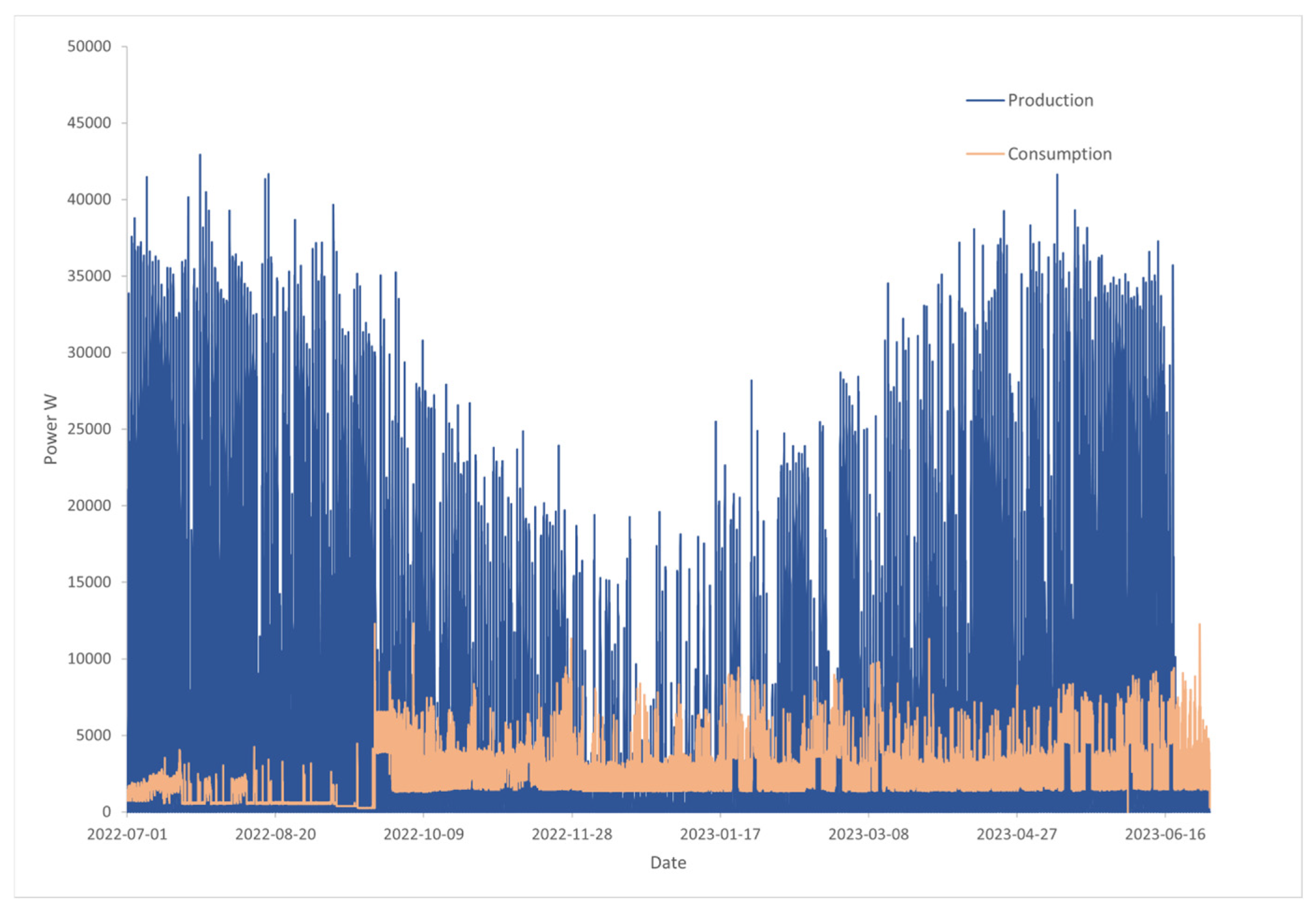
During the period from June 2022 to July 2023, the total consumption of the data center was 20.02 MWh, and the insufficient energy from the PV panels was 11.92 MWh. The power consumption of the data center is generally unpredictable, because it serves the entire faculty and student body with sporadic periods of demand, as in
Figure 1. The peak consumption power of the data center was 12.3 kW, while the max insufficient power requirement was 11.3 kW. During the summer season, the consumption of power increases due to high cooling power, but there are no defined rules in place to predict or manage the fluctuation. To fulfill the unpredictable demand, a reliable electricity support system should be implemented.
Another characteristic of the data center’s power consumption is that the idle power draw is low, approximately 250 W. Additionally, due to the high calculation power of the servers, most of the time, the data center is running at idle power. The fuel cell will suffer fast degradation and performance decline when it is working at a low power level for a long time. For this reason, it is better to use a battery reservoir to fulfill the low power demand of the data center; thus, a hybrid hydrogen–battery design is proposed.
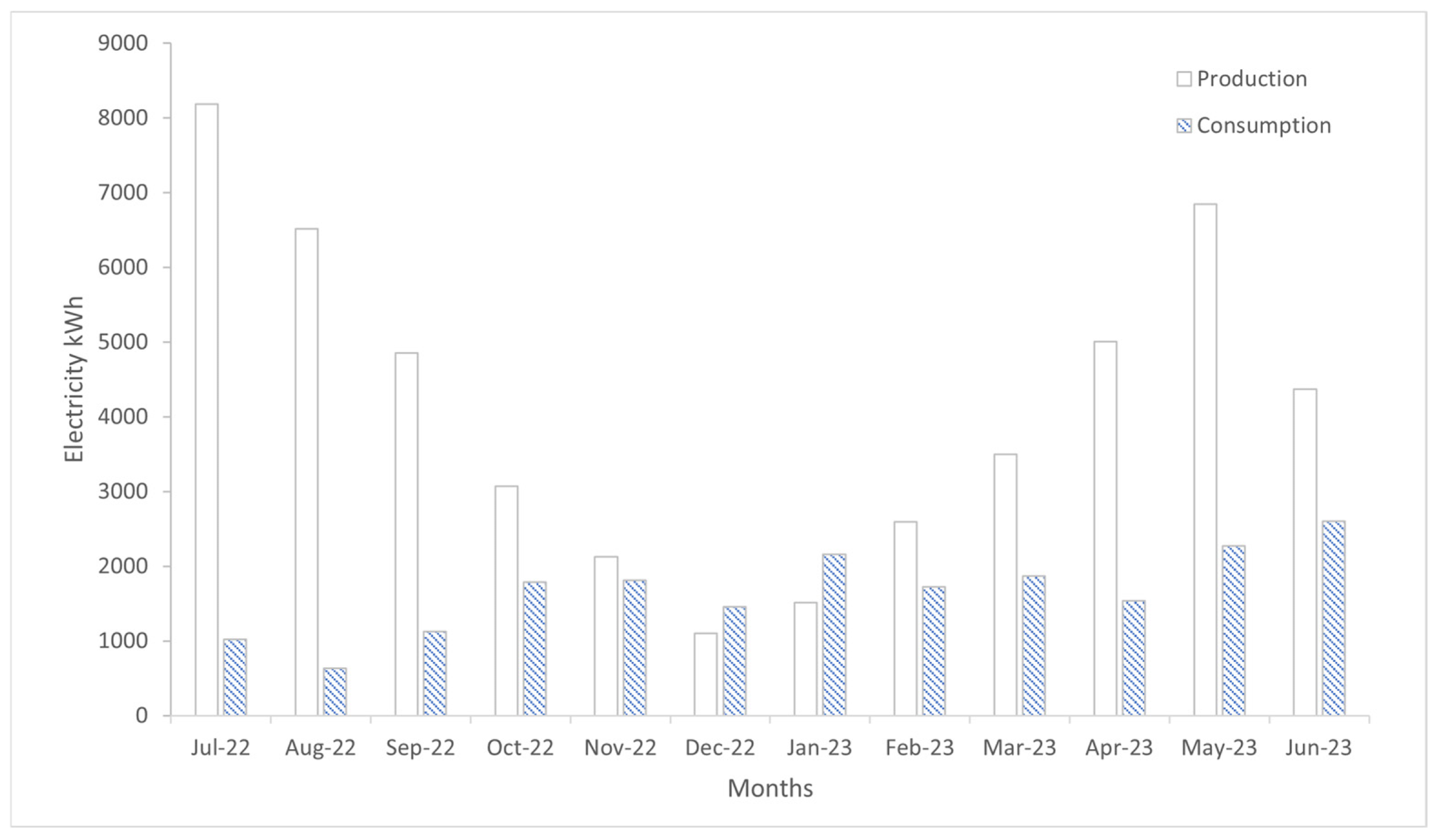
This design aims to connect the PV panels and the end user, the data center, with a hydrogen-based hybrid energy storage system. The monthly demand of the data center is given in
Figure 2. The research is based on real-time data recorded by a management system that tracks both the solar panel electricity production and data center electricity consumption on campus.
The relative decrease in PV production observed in June 2023 is primarily attributed to short-term meteorological variability. Although June generally exhibits high solar irradiation in the Nantes region, local weather conditions such as increased cloud cover can significantly affect PV output. Such variability highlights the importance of energy storage systems capable of compensating for short-term and seasonal fluctuations in renewable energy production.
2.1.2. Annual Solar Irradiation Source
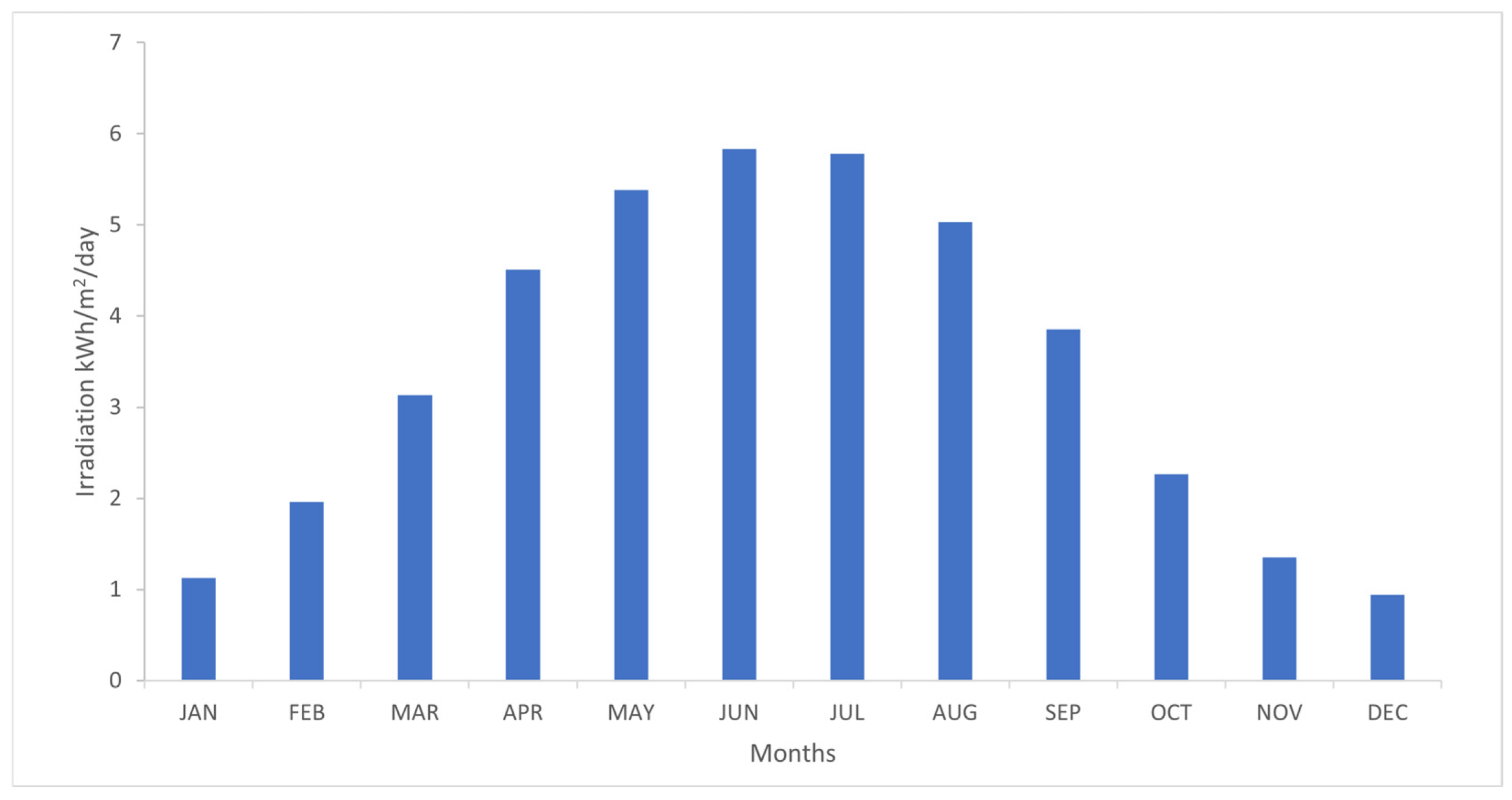
The monthly average solar irradiation of the Nantes area is given in
Figure 3, showing data from 1984 to 2021, from NASA [
28]. From this data it is obvious that the solar irradiation resource distribution in the Nantes area has a seasonal variation, which peaks in summer at 4 to 6 kWh/m
2/d, and falls to the lowest in winter at 1 to 2 kWh/m
2/d. The production of PV panels follows the distribution of irradiation, resulting in surplus energy with peak production occurring in the summer season, and insufficiency of energy in winter. From the monthly demand and irradiation resources, one can observe the mismatch between supply and demand during the seasonal period. This means that the peak demand and production occur in different seasons, causing long term surplus waste and insufficiency of data center power.
2.1.3. Mismatch
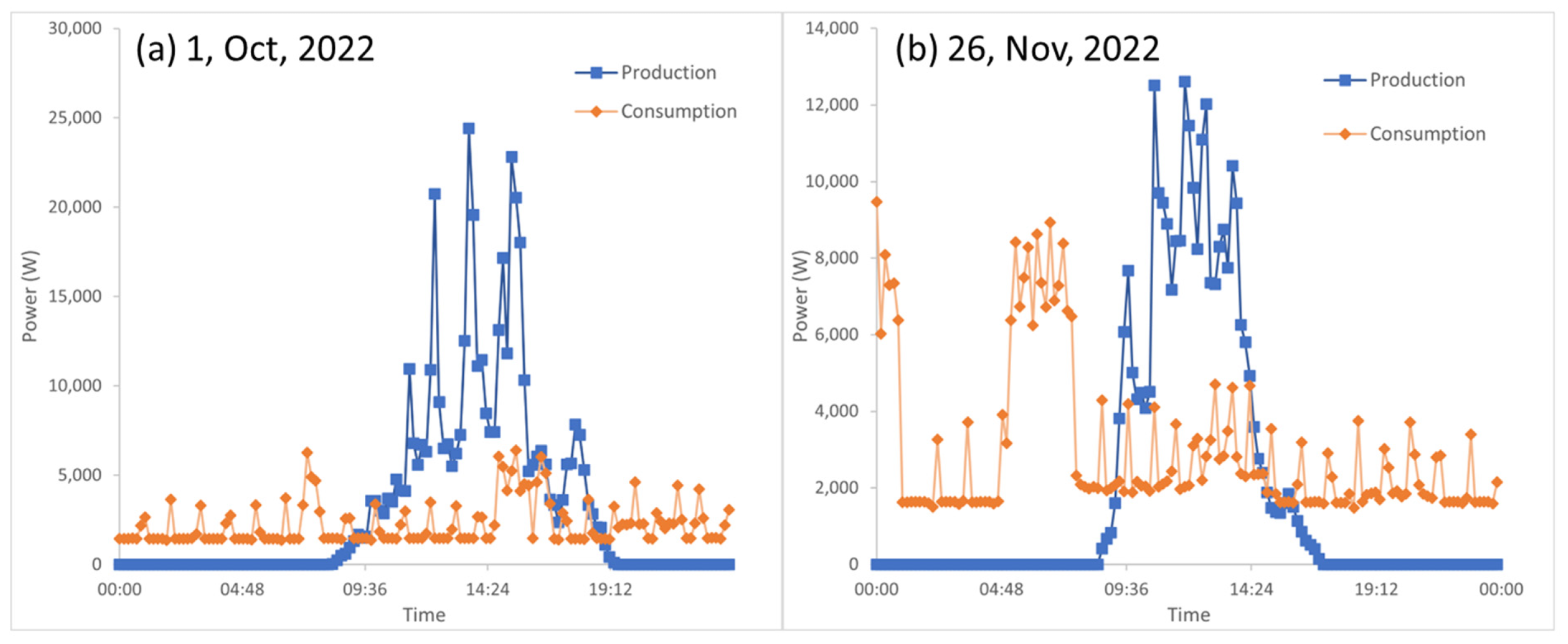
In the short term, for one day, the mismatch problem is more severe, as seen in
Figure 4. Addressing this daily variability is a key focus of our research. The PV panels only produce electricity during the daytime but the data center consumes energy 24/7, thus generating the short-term mismatch between the two sides, and the surplus energy is wasted. Additionally, the demand that remains unsatisfied will be met through the grid, causing additional carbon emissions. To solve these above problems, an energy storage system is needed.
2.2. Components of the System
To design this hydrogen-based energy system, a series of facilities are necessary to produce, store and consume hydrogen. From the literature review, it is reported that the system should include the following components: an electrolyzer, fuel cell (FC), the storage cylinder for hydrogen, and batteries for the hybrid design (
Table 2).
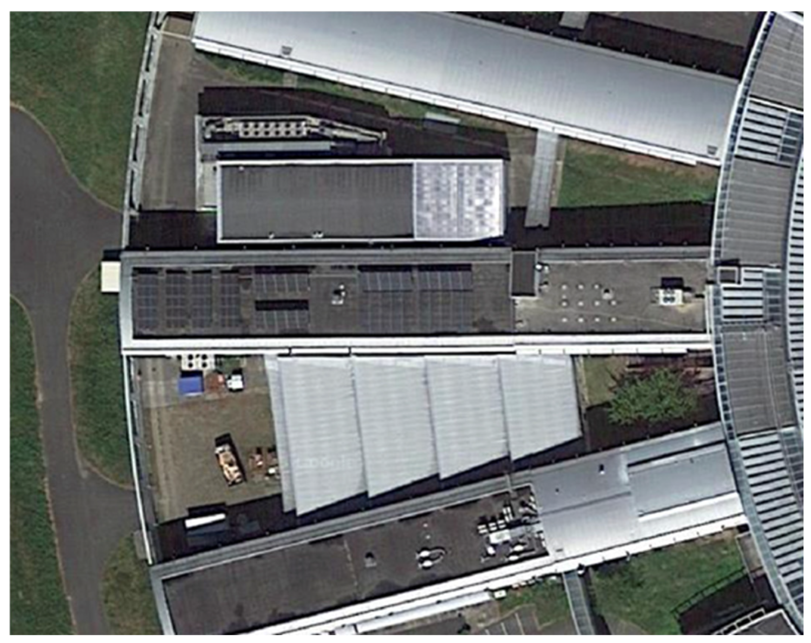
The PV panel array is installed on the roof of the main building of the IMT Nantes campus (
Figure 5), which consists of 12 groups of panels forming 50 kWp in total. The electrolyzer converts the surplus electricity to hydrogen, to store energy in chemical form via the electrolysis process. A molecule of water is split into hydrogen and oxygen of high purity. From the mid-20th century, electrolyzer technology has developed into several kinds of technologies including alkaline electrolyzers, proton exchange membrane (PEM) electrolyzers and solid oxide electrolyzer cell (SOEC) electrolyzers. Among those technologies, the PEM electrolyzer is chosen as our hydrogen source for its good adaptivity to the small scale and high energy transforming efficiency [
29]. The minimum working level of the electrolyzer should not be lower than a certain minimum level, usually around 10% for PEM electrolyzers, to avoid impurities of hydrogen in the oxygen, which may cause a dangerous explosion [
30]. Additionally, this limitation also urges the introduction of a battery to support the data center during very low demand.
The FC works in a reverse way to the electrolyzer, which produces electricity by combining the hydrogen and oxygen molecules. Some types also accept air as the oxidant, making the system more adaptive. Like the electrolyzer, the fuel cell also has a limitation for a minimum working load of 5%, which means the fuel cell should not start to respond to small demand under this value [
31].
The basic type of storage of a compressed gas cylinder, as the hydrogen tank, is chosen for its simple structure, easy maintenance and long lifetime. The battery is introduced to overcome the minimum power limits of the electrolyzer and fuel cell. The discharge depth will be set at 90% to prevent capacity loss and avoid safety issues.
To convert the energy from the PV panels, FC, and battery to meet the requirements of its user, converters are critical components for this system. The converters should convert the DC current from the PV panels or FC to support the data center, which needs AC current, and also convert the high voltage DC current to charge the battery, which needs a low voltage DC current. Thus, different types of converters are needed.
2.3. Researched Scenarios
To compare the performance of the hydrogen system and hybrid scenario, three design scenarios are researched in this paper, comparing them with the present situation, as in
Table 3. All scenarios are connected to the grid to make sure the server will not experience blackout during any circumstances.
2.4. Simulation Tools and Model Method
The assessment model is built in a Python environment, and the data is stored in MS Excel for further analysis and graphic visualization. The production and consumption data are collected every 10 min in the researched period, July 2022 to June 2023.
The simulation model operates through a parametric optimization approach. The objective of the model is to identify the optimal configuration of system components that maximizes the self-sufficiency rate (SSR) while minimizing the levelized cost of electricity (LCOE).
The main decision variables in the optimization process include: the electrolyzer nominal power, fuel cell nominal power, hydrogen storage capacity, and battery capacity.
The model evaluates the system performance for different combinations of these parameters using time-series simulation based on the recorded 10 min interval data. At each simulation step, the energy balance of the system is evaluated according to the following priority:
PV generation supplies the data center load.
Surplus PV energy is used to charge the battery.
When the battery reaches its maximum state-of-charge, the electrolyzer produces hydrogen.
During energy deficit periods, the battery discharges first.
If the battery state-of-charge falls below the defined threshold, the fuel cell is activated.
The optimization converges when the variation in the SSR and LCOE becomes negligible between successive parameter combinations.
2.4.1. Electrolyzer
The energy conversion rate of the electrolyzer used in the model is based on the market product the Cummings HyStat-10 electrolyzer, which has a nominal power of 50 kW and maximum production of 10 Nm
3/h [
32]. By this method, the H
2 production can be closer to the real production than nominal efficiency. For this analysis, it is assumed that the conversion efficiency of the electrolyzer remains constant across all power levels. Therefore, the excess energy from PV panels can be expressed as expressed by Equations (1) and (2).
Here, the is the excess energy from PV panels, and is the H2 production rate. In the simulation code, the H2 production rate is presented as the production volume in a time sampling ∆t, 10 min in our case.
2.4.2. Fuel Cell
The fuel cell also refers to a market product to obtain its energy conversion rate. The nominal power of the Proton motor PM-400-48 fuel cell is 14.2 kW, while the maximum H
2 consuming rate is 10.3 Nm
3 per hour. Thus, the following expression (Equations (3) and (4)) can be written for the fuel cell.
Here, is the insufficient power of the data center apart from the PV panel power, and is the H2 consumption of the fuel cell in ∆t.
2.4.3. Storage of Hydrogen and Battery
The storage cylinders can be standardized as a 200 L high pressure container with a maximum pressure at 350 bars. This cylinder is defined as a unit of storage, since this size of cylinder is common in the market. From the ideal gas law, this cylinder can contain 64.1 Nm
3 of H
2. Here, λ is defined as the state of storage (SOS) in the cylinder. In practice, the storage should be measured as pressure with a pressure gauge, and with the ideal gas law, the SOS level of H
2 can be presented by Equation (5).
Additionally, the battery state of charge (SOC) can be expressed by Equation (6).
while
and
are expressed by Equations (7) and (8).
To start the simulation, the hydrogen cylinder’s initial state is empty, and the battery’s initial state should be fully charged. The nominal power of the electrolyzer and fuel cell are 50 kW and 14 kW, respectively, and will be resized by further analysis.
2.4.4. Self-Sufficient Rate
In order to evaluate the performance of all scenarios, a self-sufficient rate (SSR) criterion is defined by Equation (9).
The SSR is used to indicate how much the insufficient energy of the user is satisfied by the RESs in the system. Since this study aims for energy autonomy, one of the purposes is to reduce the dependence on grid electricity.
The dynamic electrochemical behavior of the fuel cell and electrolyzer is not explicitly modeled in this study. Instead, the simulation relies on performance parameters obtained from manufacturer specifications and experimental data reported in the literature. This approach allows the model to capture realistic system-level energy flows while maintaining computational simplicity for long-term techno-economic analysis.
To justify the simplifying assumptions, a sensitivity analysis was conducted on key parameters, including the electrolyzer efficiency, fuel cell efficiency, and storage capacity. The results indicate that moderate variations (±10%) in these parameters lead to limited changes in the self-sufficiency rate (within 2–3%) and LCOE (within 5–8%), confirming the robustness of the simplified modeling approach for long-term system evaluation.
While dynamic models of electrolyzers can capture transient behaviors more accurately, they significantly increase computational complexity. Since the objective of this study is long-term techno-economic optimization based on 10 min time-step data, the use of steady-state performance parameters is considered appropriate. This approach is consistent with several system-level studies and provides reliable results for energy flow and economic analysis.
The manufacturer parameters used in this study are derived from experimentally validated performance curves under standard operating conditions. These data are widely used in system-level simulations and provide a reliable representation of component performance.
Although dynamic electrochemical effects (e.g., transient response and degradation mechanisms) may influence short-term operation, their impact on long-term energy balance and economic indicators is relatively limited. This assumption is supported by the sensitivity analysis, which shows that variations in component efficiency have only a moderate effect on system-level results.
2.5. Economic Estimation Method
To compete with conventional energy sources, RESs not only need to provide benefits in the environmental aspect, but also economic merits. Fortunately, the production price of PV panels has experienced a steep decline in past decades, making it the most competitive energy resource among all, including both RESs and fossil fuels. However, the storage system will additionally increase the LCOE of the PV panels, so here a method to estimate this impact is built.
A price list for the components of the hydrogen system and battery is presented here in
Table 4. Those prices are based on the market price and recent research.
The main criteria of the economic estimation are the net present value (NPV) of the facilities and the LCOE, presented by Equations (10) and (11), respectively.
where the R
t, r and t are the net cash flow in period t, discount rate (5%) and number of time periods, respectively.
where I, M, F, E, and n are the initial investment expenditure, maintenance and operation expenditure, fuel expenditure (none in our study), total electricity generated, and lifespan of the project (15 years in our study), respectively.
The levelized cost of electricity (LCOE) is calculated by considering the total lifecycle cost of the system divided by the total electricity supplied to the data center over the project lifetime.
The lifecycle cost includes:
Initial capital investment (electrolyzer, fuel cell, storage cylinder, battery, converters).
Operation and maintenance costs.
Component replacement costs during the 15-year project lifetime.
The total electricity supplied corresponds to the cumulative energy delivered by the hybrid storage system to the data center during the simulation period.
2.6. Environmental Impact Methods
As climate change progressively changes our lives to a deeper extent, and rising temperatures, extreme weather events and ecological disruptions indicate the urgent need for immediate actions, environment impact concerns are now at the forefront for all products. To compare the environmental impact of each scenario, their carbon footprints, using methods developed by databases and research, are estimated.
The carbon footprint of the present scenario is based on the fact that all the insufficient electricity outside of the PV panels’ supply is from the grid. In 2022, the CO
2 intensity of electricity production was 56 g/kWh in France [
39]. Thus, for the carbon emissions of the present scenario in 15 years, the total carbon footprint of the present situation will be 4961 kg CO
2.
The carbon emissions of other scenarios are mainly from the electrolyzer, fuel cell and battery. The carbon footprints of other facilities are ignored, including from inverters, compressors, tubes and other accessories, because they have a longer lifespan and lower emissions during manufacture. Based on the report of Zhao et al. [
40], the electrolyzer’s CO
2 emissions can be estimated as 44.1 kg CO
2 eq. per ton of H
2 production. For the fuel cell, from Simons et al. [
41], the CO
2 emissions are 25 kg CO
2 eq. per kW of the fuel cell over its lifespan. And from openLCA, the Li-ion battery’s carbon footprint is 0.927 kg/kWh for its lifecycle.
3. Result Discussion
With the help of the Python program (version 3.13.5), the simulation gives the performance of the energy reliability, economic merits and environmental impacts of different levels of the FC and electrolyzer sizes. The sensitivity analysis of these performances shows the optimal sizes of the main hydrogen components from both the technical and economic aspects. The carbon footprint analysis provides supporting proof for the hybrid design. Additionally, to describe the working process of the optimal scenario, an operation policy is also given.
3.1. Sensitivity Analysis for Optimization
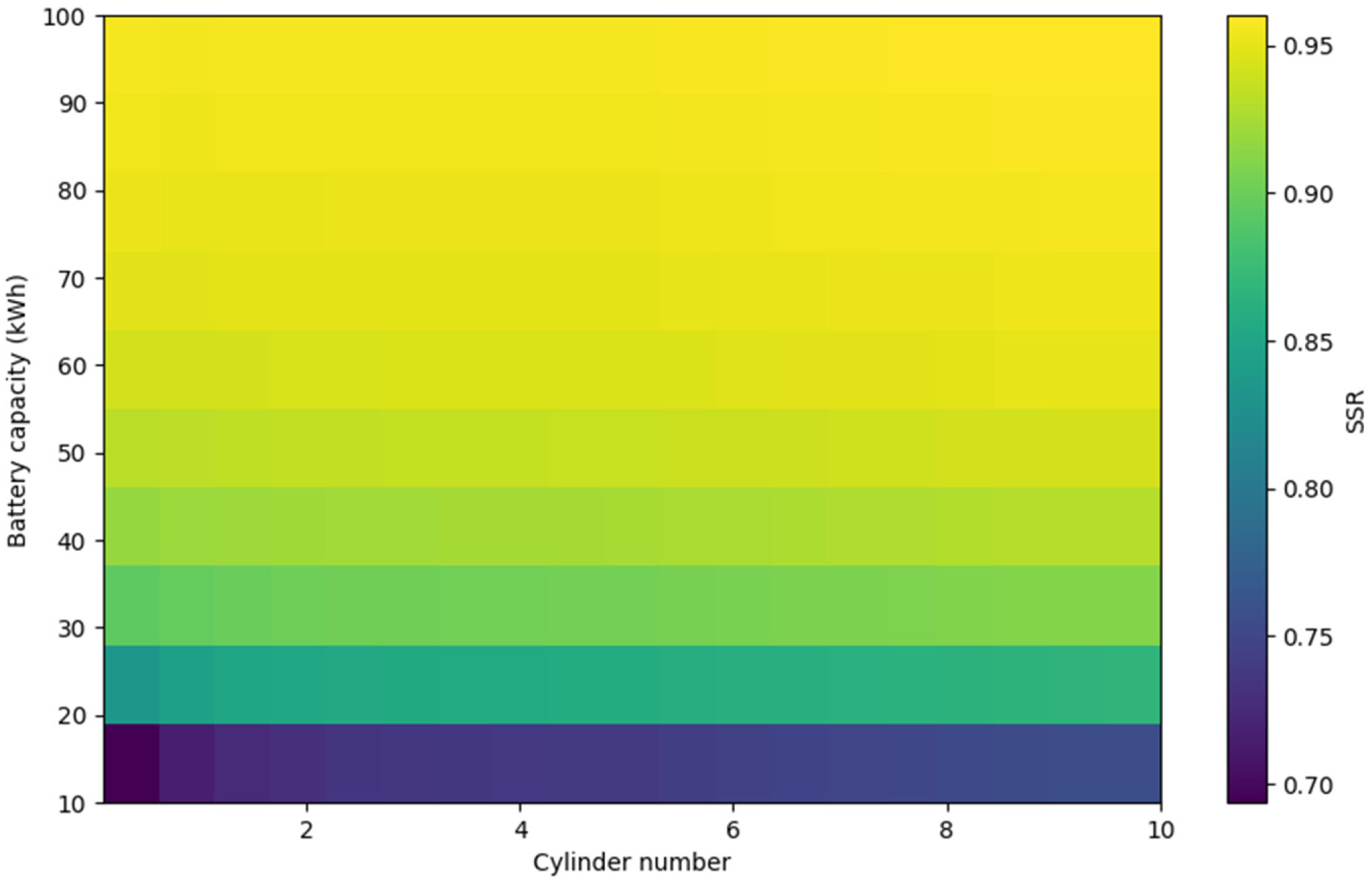
First of all, we focus on the performance of the system in view of the SSR to evaluate how much RES energy can be used via the hybrid design. A sensitivity analysis of the relation between the cylinder number and battery capacity is finished in the range of 0.1 to 10 standard cylinders’ volume and 10 to 100 kWh of battery.
Figure 6 shows the SSR varying with the number of cylinders and battery capacity. This result demonstrates the battery size only heavily influences the SSR under 50 kWh, with the SSR increasing when the battery capacity becomes larger. However, when the battery capacity exceeds 50 kWh, its impact on the SSR becomes less significant, while the SSR is more stable than with smaller battery capacities. Additionally, from this figure, it can be noted that the hydrogen cylinder number has a very limited impact on the SSR when the cylinder number is higher than one; therefore, one 200 L cylinder is large enough to maintain a high SSR. From this analysis, a 50 kWh battery and one cylinder are suitable to build the system.
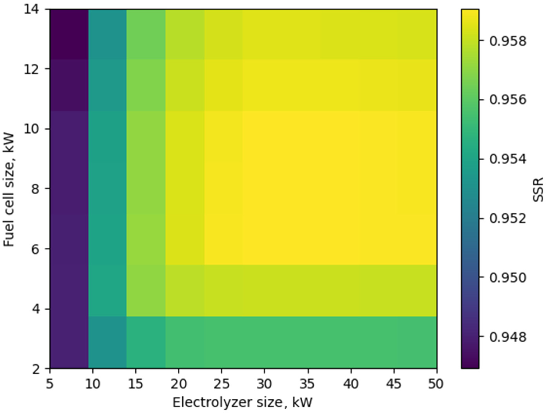
To further find the optimal size of the electrolyzer and fuel cell, the sensitivity analysis of the SSR on different sizes of the electrolyzer and fuel cell is investigated. In this analysis, the modeled electrolyzer sizes range from 5 kW to 50 kW, increasing in increments of 5 kW. The fuel cell sizes modeled range from 2 kW to 14 kW, increasing in 2 kW increments. Thus, a total of 70 pairs of sizes are simulated, as in
Figure 7. It is noticed that the SSR is kept stable (94.7% to 95.8%) while the sizes vary. This fact indicates that the battery has a great buffering ability to adapt to the change of hydrogen facilities.
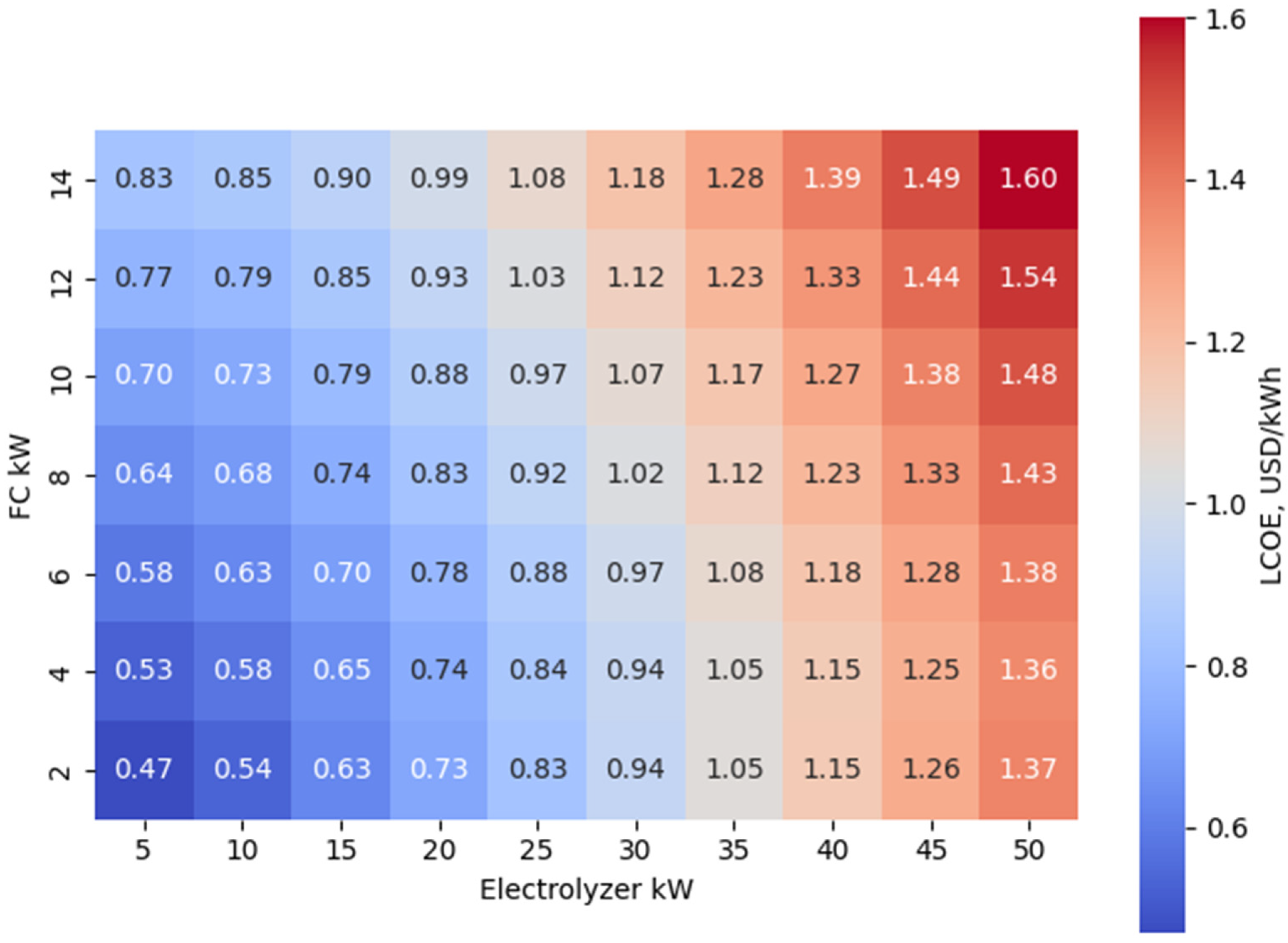
From the economic aspect,
Figure 8 shows the LCOE varying with the size of the fuel cell and electrolyzer, from 0.47 to 1.60 USD/kWh. Since the PV panels are installed in advance, the LCOE in this paper does not contain the cost of the PV panels and their operation and maintenance. In this situation, it can be found that the LCOE naturally increases with the size of both the electrolyzer and fuel cell, since those two components are the main source of costs, proportional to their capacity. Based on the analysis, sizes can be proposed, namely, the electrolyzer as 5 kW and fuel cell as 2 kW, with an LCOE of 0.47 USD/kWh.
Although the photovoltaic installation was implemented before the development of the storage system, it is useful to estimate its cost in order to evaluate the total investment required for a similar project.
Based on recent market data, the average installation cost of photovoltaic systems in Europe ranges between 900 and 1200 US$/kWp depending on the system size and installation conditions. For the 50 kWp PV installation considered in this study, the estimated investment cost would therefore range between 45,000 and 60,000 US$. Including this cost provides a more complete representation of the total system investment for future implementations.
In addition to the hybrid system, the LCOEs of the battery-only and hydrogen-only scenarios were also evaluated. However, the hybrid system provides the best compromise between cost and environmental performance, combining the efficiency of batteries with the long-term storage capability of hydrogen. This trade-off highlights the advantage of hybrid configurations for applications requiring both reliability and sustainability.
3.2. Carbon Footprint
With the method mentioned before, the carbon emissions from all four scenarios are reported in
Table 5. It is clear that the three researched scenarios can all save a large amount of carbon emissions in comparison to the present situation. Even though the emission factor in France is far lower than the average level of the European Union and the world, the emissions from the grid still should be counted because 10 tons CO
2 will be emitted in 15 years in the present situation. According to the results, the hybrid scenario can save the most carbon emissions, with an 89.6% saving compared with the present situation. With a high SSR of 95%, only a very small part of the electricity is from the grid. For this reason, the hybrid scenario is proven again to be the optimal scenario among the researched designs.
Voltage stability at the load side is an important aspect of microgrid operation. Recent studies have proposed voltage–power self-coordinating control strategies based on adaptive droop control, enabling optimal reactive power sharing between distributed energy resources [
42]. Although this study does not explicitly model inverter-level control, such approaches could be integrated into the proposed system to enhance voltage stability and improve overall system performance.
3.3. Operation Policy of the System
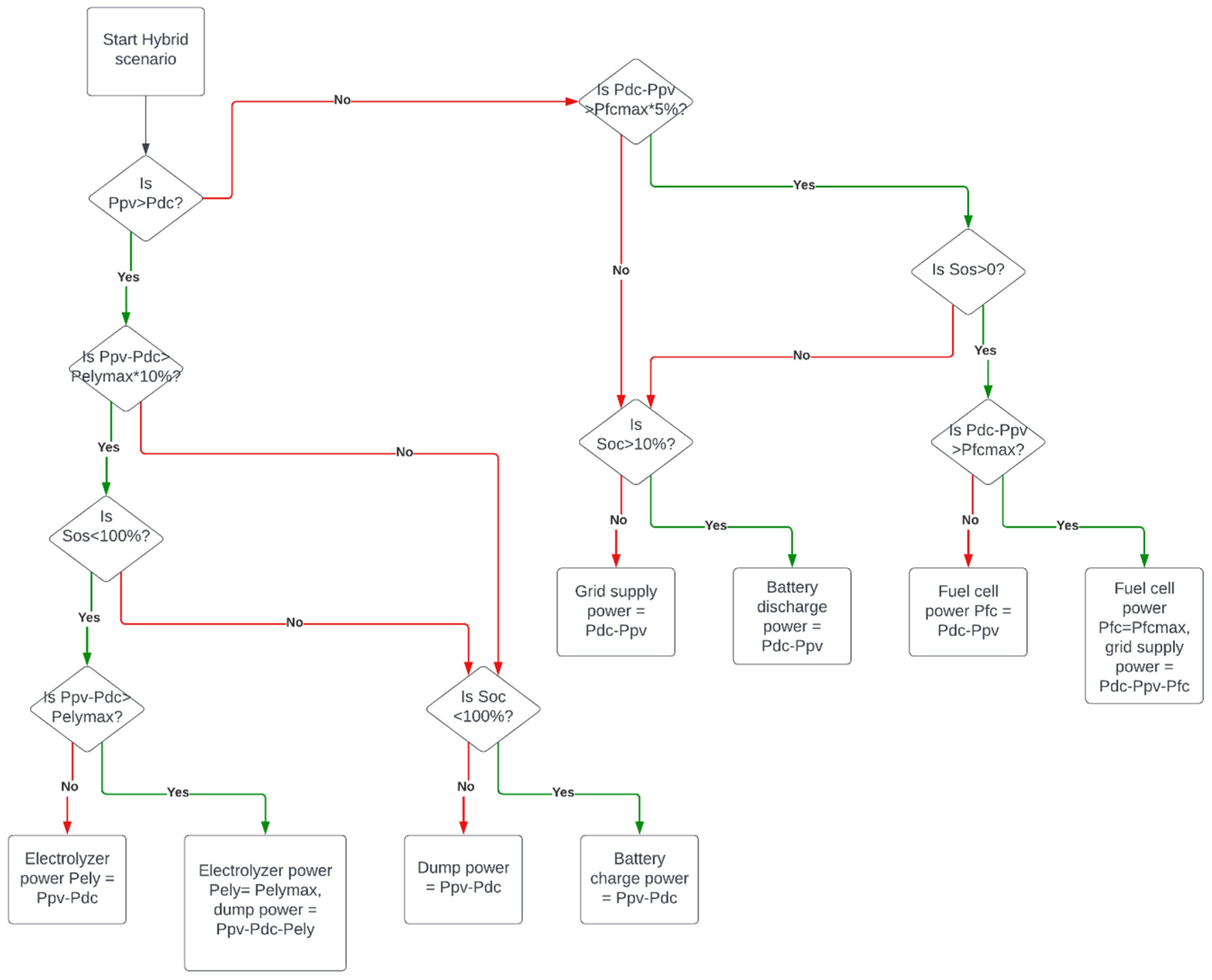
The objective of this energy storage system is to reduce the use of electricity from the grid and use the largest amount of RES energy. Based on this strategy, the operation policy diagram in
Figure 9, in which hydrogen is the primary energy source and the battery is a second reservoir, is established. In the case of depleted hydrogen and battery resources, the grid remains consistently connected to assume control and ensure an uninterrupted power supply.
Temperature plays a critical role in the performance and durability of PEM fuel cells. Elevated operating temperatures can accelerate membrane degradation, increase catalyst corrosion, and affect water management within the membrane electrode assembly. In small-scale systems such as those considered in this study, thermal management becomes particularly important during periods of high ambient temperature, especially in summer conditions when cooling requirements for data centers are already high. Adaptive thermal management strategies, including active cooling control and temperature-dependent operating strategies, can improve fuel cell durability and system efficiency. Integrating temperature monitoring into the energy management strategy may therefore enhance long-term system reliability.
Due to the limitations of local grid policy, it is not allowed to sell the dump power of the PV panels back to the grid. Therefore, the dump power still exists because the capacity of the PV panels is larger than that of the consumer. Future work will be focusing on introducing more users of the school to the system.
Lithium-ion batteries are subject to both calendar aging and cycle aging mechanisms. Calendar aging refers to the gradual loss of capacity over time even when the battery is not actively used, while cycle aging results from repeated charge and discharge cycles.
Typical lithium-ion batteries exhibit annual degradation rates between 2% and 3% depending on the operating temperature, depth of discharge, and cycling frequency. Over the 15-year project lifetime considered in this study, partial battery replacement may therefore be required to maintain system performance.
The hybrid energy management strategy follows a rule-based control logic designed to maximize the renewable energy utilization while protecting the system components from excessive operating stress.
The control rules are defined as follows: the PV electricity first supplies the data center load. If the PV generation exceeds the load demand, the surplus energy is used to charge the battery. When the battery state-of-charge reaches its maximum threshold, the electrolyzer converts the remaining surplus electricity into hydrogen. During periods of insufficient PV generation, the battery is discharged to supply the load. If the battery state-of-charge falls below a predefined threshold (SOCmin), the fuel cell is activated to provide additional power. If both the battery and hydrogen storage are depleted, the grid supplies the remaining demand.
Recent studies on electric–hydrogen coupled microgrids have proposed advanced multi-mode control strategies, such as flexible grid–connected/off-grid control frameworks based on hierarchical coordination. Compared to these approaches, the control strategy adopted in this study relies on a rule-based hierarchical logic, which prioritizes simplicity and ease of implementation. While advanced control methods can improve dynamic stability under rapid switching conditions, the proposed approach remains effective for long-term energy management and techno-economic optimization. The integration of such advanced control frameworks could further enhance system stability and responsiveness under highly dynamic operating conditions.
3.4. Optimal Scenario Result
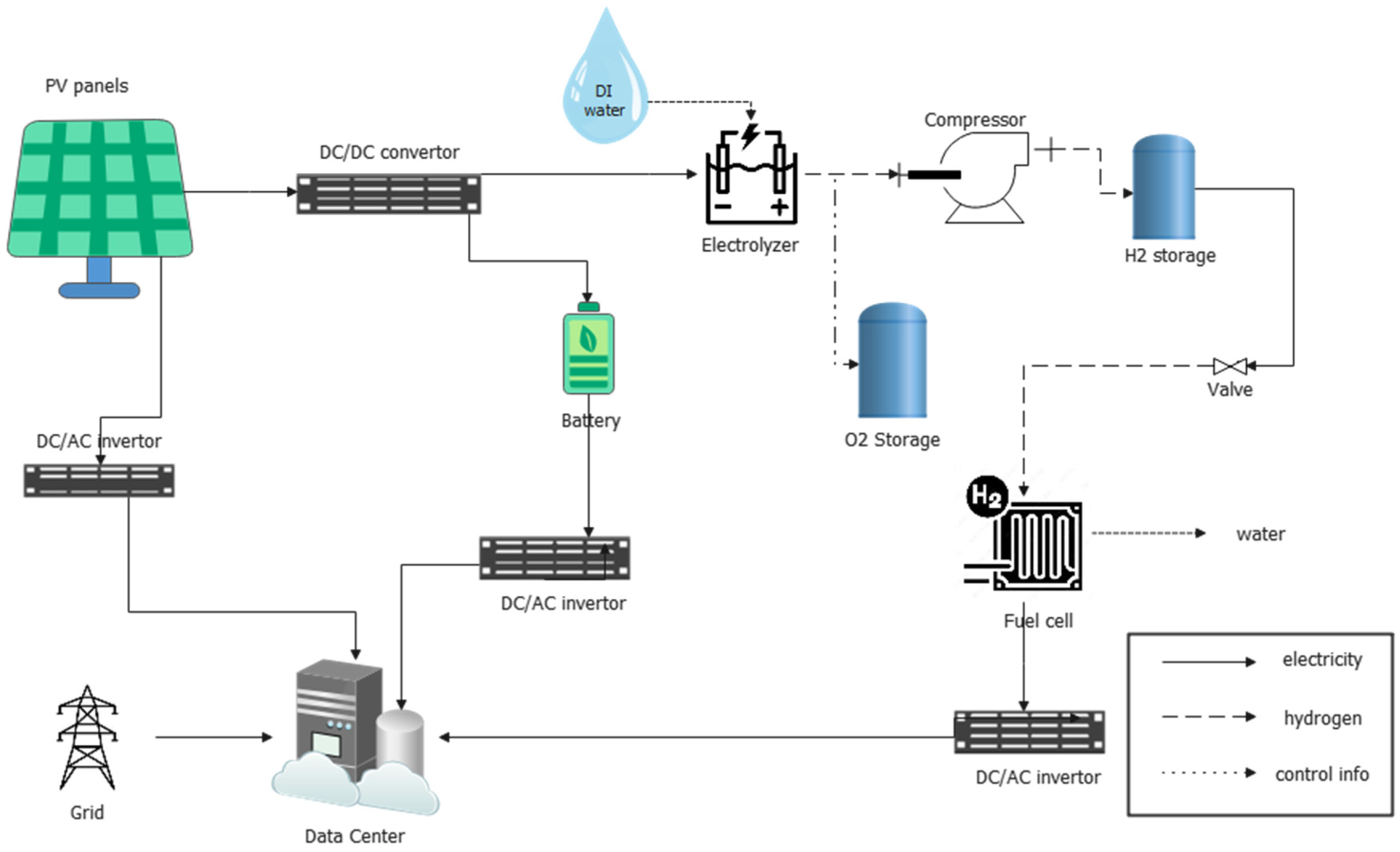
As discussed above, the hybrid scenario is found to be the optimal one, with a configuration schema given as in
Figure 10. The capacity of the electrolyzer, fuel cell, hydrogen cylinder and battery should be 5 kW, 2 kW, 200 L, and 50 kWh, respectively (
Table 6). Other facilities, including inverters and valves, should be capable of meeting these specifications.
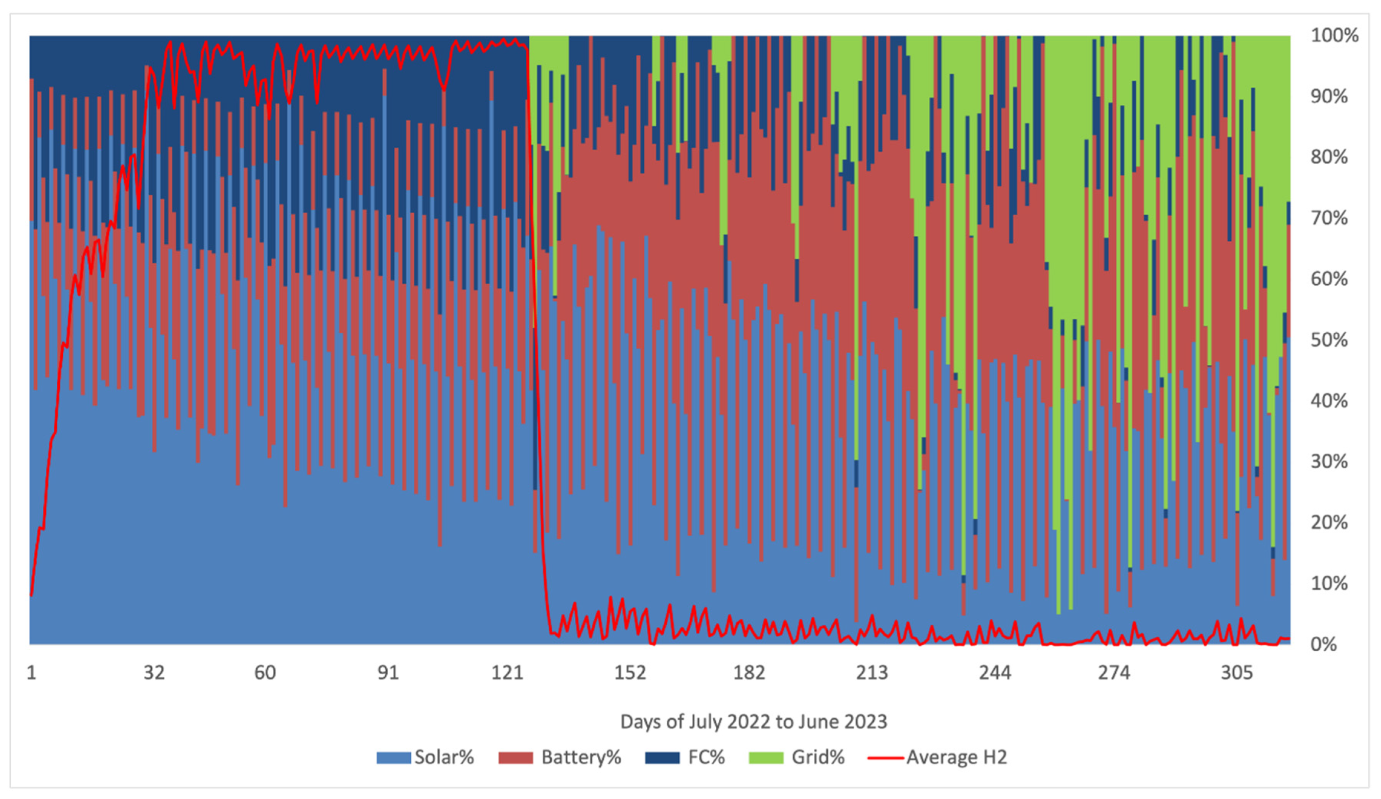
In this scenario, the energy contribution distribution and the hydrogen level are varying like in
Figure 11. This figure shows that the grid electricity is only introduced at the beginning of semester in September and in rainy winter. Most times of the year, the energy storage system can fully support the data center’s consumption, proving that the hybrid design has good adaption to insufficient irradiation weather conditions.
Fuel cell durability is strongly influenced by operating conditions, particularly in renewable energy systems characterized by intermittent operation. One important phenomenon observed in PEM fuel cells is reversible voltage loss, where part of the performance degradation caused by dynamic operation can be partially recovered during resting periods.
This recovery phenomenon has been observed in several experimental studies and can be attributed to catalyst surface restructuring and temporary removal of reaction intermediates that block active sites. In hybrid energy systems, the presence of battery storage can reduce rapid load fluctuations and allow the fuel cell to operate in a more stable regime. Such operating conditions may reduce irreversible degradation mechanisms and extend the effective lifetime of the fuel cell system.
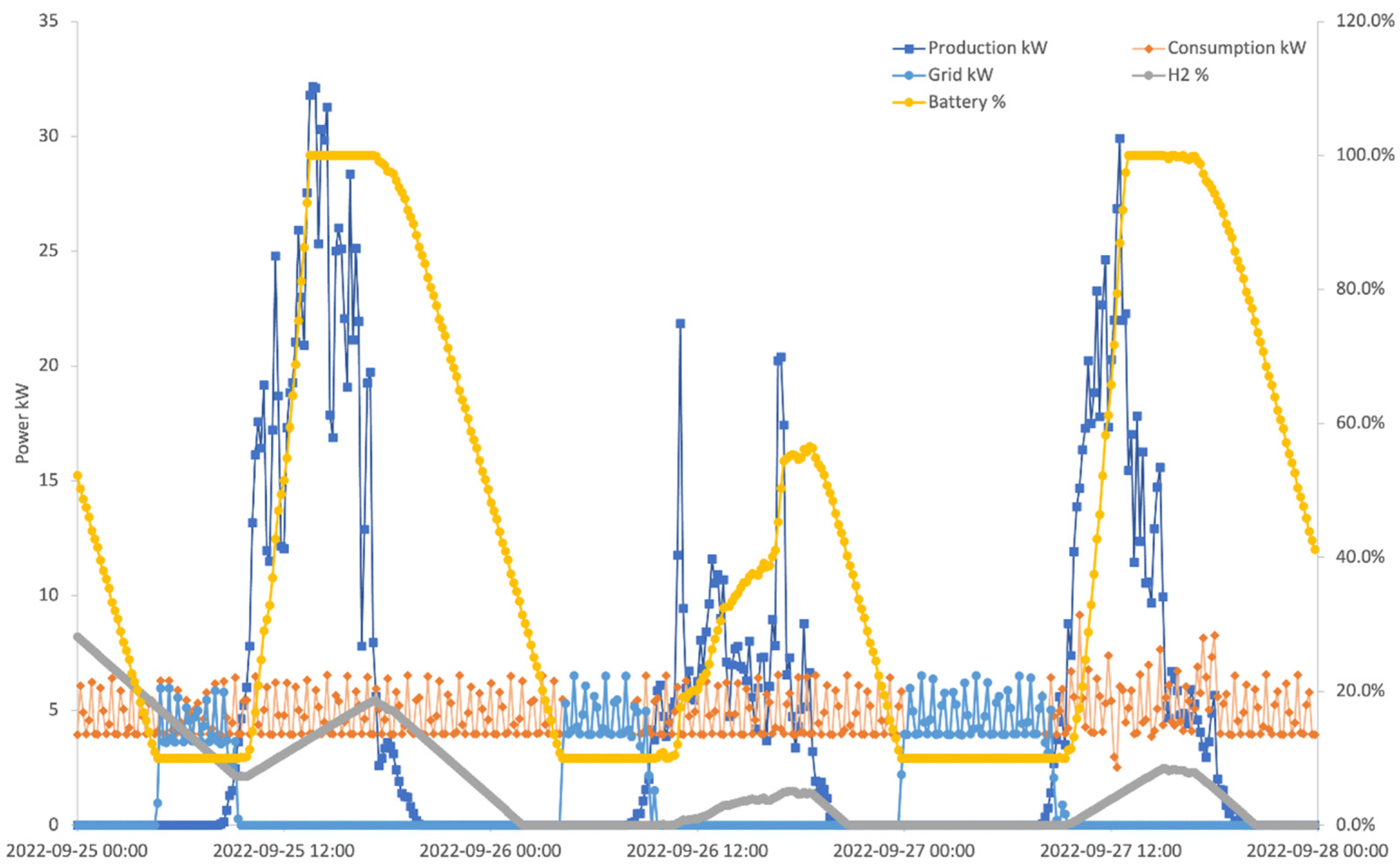
For better understanding of the process, the plot of power of PV panel production, data center consumption, H
2 storage level, battery charging level and the power of the grid during 25 to 27 September 2022 is given in
Figure 12. This period is chosen because it shows a typical weather condition in Nantes, a partly sunny day followed by two cloudy days. In the first day, during the daytime, the H
2 cylinder and battery are both charged because the PV panels are producing more electricity than the demand of the data center. At night time, the H
2 and battery are both being consumed, until the H
2 is fully used up and the battery discharging depth reaches its limit. Then, the grid continues to support the user. In the second day’s daytime, the weather is worse than the previous day; thus, the charging of the battery and H
2 is not sufficient.
From the simulation, the hybrid design system produces 217 kg of H2 per year, and provides 3331 kWh/year of electricity for the end user, resulting in an LCOE of 0.47 US$/kWh, supplying 95% of the insufficient part of energy consumption.
To provide a clearer perspective on the economic performance of the proposed system, the obtained LCOE value can be compared with existing electricity prices and alternative storage technologies. In France, the average industrial electricity price ranges between 0.15 and 0.25 US$/kWh depending on consumption levels and contractual tariffs.
Lithium-ion battery storage systems typically present LCOE values ranging between 0.20 and 0.40 US$/kWh depending on the cycle life, system size, and replacement costs. These systems offer high round-trip efficiency (85–95%) but are generally limited to short- to medium-duration energy storage applications due to capacity degradation over repeated cycles. Hydrogen-based energy storage systems, although characterized by lower round-trip efficiency (typically 30–45%), offer significant advantages for long-duration and seasonal energy storage. The hybrid architecture proposed in this work leverages the high efficiency of batteries for short-term fluctuations while using hydrogen storage to address long-term mismatches between renewable production and energy demand.
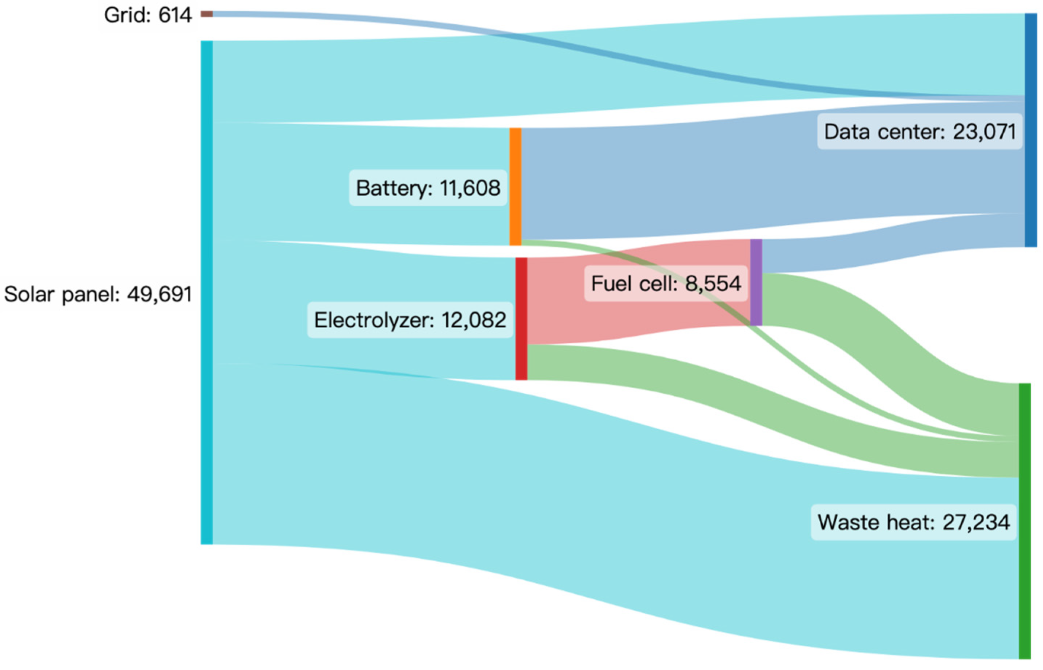
The final energy flow is given in
Figure 13, where it can be found that the hydrogen facilities have low energy transforming efficiency, since most of the energy is wasted in the process of electrolysis and the regeneration of electricity by the fuel cell. Under this situation, the efficiency limitations remain a key obstacle for implementing the hydrogen-based energy storage for wider application.
The round-trip efficiency of the hydrogen storage subsystem, including electrolysis and fuel cell conversion, is estimated to be in the range of 30–40%, which explains the significant energy losses observed in the Sankey diagram.
A stage-wise analysis shows that the main losses occur during electrolysis and electricity regeneration processes.
Future improvements could include the use of high-efficiency technologies such as solid oxide electrolysis cells (SOECs), which offer higher conversion efficiencies, as well as optimized hydrogen storage solutions (e.g., higher pressure tanks or liquid hydrogen storage). These advancements could significantly enhance the overall system efficiency and economic viability.
To better position the results of this study within the existing literature, a comparison with several recent studies on hybrid renewable energy systems is presented in
Table 7. Compared with these studies, the LCOE obtained in the present work is higher, mainly because the system is designed at a smaller scale and prioritizes energy self-sufficiency rather than cost optimization. Nevertheless, the proposed hybrid architecture demonstrates the feasibility of integrating photovoltaic generation, battery storage, and hydrogen technologies to increase renewable energy utilization and reduce dependence on the electrical grid.
This comparison highlights the relevance of hybrid hydrogen–battery systems for improving renewable energy integration in critical infrastructures such as data centers.
4. Conclusions
Energy storage is becoming more important as renewable energy occupies a larger shares of global energy production. Among the variety of storage technologies, hydrogen as an ideal energy carrier has promising prospects, with well-adapted characteristics including a high energy density and zero carbon emissions. To realize a hydrogen-based energy storage system, this paper has demonstrated the technical and economic feasibility along with the design. In this paper, a hydrogen-based hybrid with a battery energy storage system has been proposed. With a simulation executed with Python, its technical, economic and environmental performances have been illustrated, comparing them with the present scenario, a hydrogen scenario and a battery design.
The main innovation in the method used in this study is the use of market products’ energy transformation efficiency rather than the theoretical energy balance of the electrolyzer and fuel cell. This makes the simulation closer to real-world conditions. Additionally, with real production and demand data, this work provides more specific simulation, rather than approximate estimation using the total demand or monthly demand and regional solar radiation data.
Another observation of this paper is that the hydrogen facilities still have a higher initial investment than a battery, and the minimum work load level problem of both the electrolyzer and fuel cell makes the battery a meaningful supplement for the system. It is also noticed that the system connected to the grid sacrificed a very small share of carbon emissions but brings a better LCOE, rather than building a 100% RES-supported project at a high price.
The proposed hybrid system demonstrates a high level of performance, achieving a self-sufficiency rate (SSR) of 95%, significantly reducing dependence on the electrical grid. In addition, the system enables a reduction of approximately 8.97 tons of CO2 emissions over a 15-year lifetime compared to the conventional grid-powered scenario. These results confirm the effectiveness of the hybrid hydrogen–battery architecture in enhancing both energy autonomy and environmental sustainability for data center applications.
Future works will focus on integrating more users of the school and maximizing the RES energy from variety sources.