1. Introduction
The occurrence of methane in hard coal seams is a threat to occupational safety in underground coal mines. It results in methane emission to the atmosphere, contributing to the greenhouse effect [
1,
2,
3]. The management of coalbed methane (CBM) is therefore important in terms of safety and environmental aspects with particular attention given to its increasing use as an energy resource worldwide. In many countries, like, e.g., the United States, Canada, Australia, and China, the technologies enabling methane extraction and its use in energy production are under development [
4,
5]. Methane released from coal seams is directed to the surface using ventilation and methane drainage systems. The latter is particularly important regarding the labour safety, environmental (greenhouse gases emission mitigation), and power generation aspects related to the CBM [
6,
7,
8]. However, despite decades of development, proper design of methane capture using coal seam drainage systems and enhancement of drainage efficiency remain active areas for research interest and practical importance [
9]. Commonly employed methane drainage techniques can be divided into three types based on the trajectory of the borehole: surface to in-seam (SIS), underground to in-seam (UIS), and cross-measure borehole gas drainage [
10,
11,
12]. The methods of methane drainage with long vertical boreholes drilled from the roof are also reported in the scientific literature [
13]. Considering the time needed to drain the rock mass with the use of methane drainage boreholes, one may distinguish advanced methane drainage and ongoing methane drainage performed during the exploitation of coal seams. In the case of Poland, the low permeability of coals limits the efficiency and applicability of the advanced methane drainage method, necessitating reliance on ongoing drainage methods during active extraction.
The cross-measure borehole gas drainage technique is commonly applied in hard coal mines with high methane content to control gas emissions. Present drainage techniques for underground coal mine methane (CMM) utilization/reduction include cross-measure and horizontal boreholes. Of the two, long horizontal/directional boreholes in the coal seam have the advantage of being less labour-intensive. The purpose of horizontal drilling in mines is to reduce methane concentrations at the extraction site prior to commencement of mining operations and to protect the longwall face from methane migration from surrounding coal seams that are not affected by mining [
14]. Recently, the application of long directional drilling technology has improved the technique of conducting the methane drainage process using borehole trajectory control, eliminating the need for conventional straight-line drilling. Directional drilling technology is becoming increasingly popular for draining gas from adjacent seams (or rock mass) [
15]. Long directional boreholes can be drilled into a coal seam, across a coal seam, or as a combination of both. This results in enhanced efficiency of methane drainage before mining [
16,
17].
Long directional boreholes technology has been successfully applied in the United States, Australia, and—with moderate success—in China [
16,
18]. It was also tested at the Amasra Coal Mine in Turkey [
19] and in Ukraine, where a preliminary study of technical feasibility and economic viability was developed after tests on long directional boreholes. In Poland, the technique of directional drilling has been employed by the two largest mining companies, extracting copper (KGHM Polska Miedź S.A., Lubin, Poland) and coking coal (Jastrzębska Spółka Węglowa S.A., Jastrzębie-Zdrój, Poland) to identify the structure of the rock mass and the geological disturbances present in it, as well as to dewater part of a deposit [
20].
Despite these technological advances, a crucial knowledge gap continues: the relationship between geo-mechanical processes and induced mining activity and the chrono spatial performance of directional drainage boreholes remains poorly understand and not sufficiently integrated into drainage system design. Considering the geo-mechanical aspects, the migration of methane in the rock mass in the regions of mining operations depends mainly on the geological structure of the rock mass, the original state of stress, changes in the state of stress in the vicinity of the mining workings and the accompanying destruction of the original structure of the rock mass. In the case of coal mining with the use of a longwall system for caving, the direct roof, from which the caving zone is formed, and the main roof, which forms the zone of cracking and deflection may be distinguished [
21,
22,
23,
24]. When the location of methane drainage boreholes is considered, the phenomena occurring in the basic roof, i.e., cracking and deflection, seem to be crucial. Under the geological conditions of the Upper Silesian Coal Basin (USCB) the rock mass consists of alternating layers of rocks of different stiffness. The roof of the coal seams consists of shale, siltstone and sandstone formations that differ significantly in terms of stiffness and strength [
25]. Deformations of the rock mass built in such a way in the vicinity of coal panels exploited for caving cause the formation of a fundamental concentration of stresses in the individual layers of the roof, the greater the variation in their stiffness. As a result of these phenomena failure and additional cracking of rock mas occur [
21,
26]. The undisturbed rock mass has a system of primary discontinuities, fractures, cracks, and faults that are a natural feature of the rock mass and provide a natural migration network for methane [
27,
28,
29]. This natural divisibility of the rock mass is overlaid by a network of cracks resulting from exploitation deformation [
26,
28,
30], with the regions where cracks of this type will occur being determinable [
31,
32,
33,
34]. The above provides an important guideline for the location of methane drainage boreholes. Considering the general assumptions for locating methane drainage boreholes in the roof above the exploitation in the fracture zones above the goaf [
35,
36], the boreholes should be in layers and regions where exploitation cracks. Such stresses activate crack networks [
31,
37] as possible pathways for methane migration. Although predictive models exist for fracture zone geometry, the existing literature predominantly treats borehole drainage performance as a static function of initial placement, neglecting temporal evolution as mining progresses and geo-mechanical conditions change. Furthermore, interactions between adjacent coal panels, particularly goaf overlap effects and their influence on drainage efficiency, have received limited attention, despite their practical significance in multi-panel mining layouts. This study addresses these gaps through an integrated analysis framework combining directional borehole drainage technology, finite element geo-mechanical modelling, and ventilation aerodynamic simulation applied to the 501 coal seam in the Staszic–Wujek mine (part of the Polska Grupa Górnicza S.A.), located in the Upper Silesian Coal Basin (USCB), Katowice, Poland. The main research objective of the study was the assessment and comparison of the effectiveness of the methane drainage system in the context of methane hazard, the occurrence and release of methane, and the efficiency of capturing it through drainage boreholes of classical drainage and directional boreholes. Furthermore, relevant information for designing and managing the methane drainage systems in coal mines, enabling increased efficiency of the work carried out in the area concerned, is also given. The analysis additionally considers geo-mechanical factors affecting the location of drainage boreholes, with the aim of identifying the optimal locations for the placement of the boreholes to ensure effective and safe capture of methane from the coal seam being mined, as well as from the developing methane desorption zone in the vicinity of the coal panel to be extracted.
This study makes the following key contributions: (i) an integrated analysis framework combining directional borehole drainage technology, geo-mechanical FEM modelling, and ventilation aerodynamic modelling for a single case study in the USCB; (ii) the geo-mechanically founded interpretation of drainage performance variability linked to goaf interaction between adjacent coal panels; and (iii) practical borehole placement recommendations transferable to similar high-methane mining conditions. Using the case study of coal seam 501, coal panel II/C, at the Staszic–Wujek coal mine, the paper aims to provide practical guidance and lessons that can be applied to similar conditions at other hard coal mines in order to increase the efficiency of methane drainage systems and improve labour safety by a more in-depth understanding of the geo-mechanical conditions of drainage boreholes’ location.
The characteristics of mining and geological conditions and an analysis of methane hazards in the context of the methane content of coal seam 501 is presented in the paper along with the ventilation and methane drainage systems, with particular emphasis on the use of directional boreholes as an effective method of methane drainage. Next, the analysis of the results of methane separation and assessment of the effectiveness of methane capture through directional boreholes is performed. The air and aerodynamic potentials in longwall II/C are also analyzed, allowing for a better understanding of airflow and the effectiveness of the methane drainage system. In addition, geo-mechanical considerations for the location of drainage boreholes are presented, considering factors such as geological properties and mining parameters. The recommendations on the effectiveness of the applied methane drainage system in the case study of coal seam 501 at the Staszic–Wujek coal mine are also given.
In recent years, increasing regulatory and societal pressure at the European and global levels has intensified efforts to reduce methane emissions from the energy and extractive sectors, due to methane’s high global warming potential and its significant contribution to short-term climate forcing. In coal-dependent regions, particularly those characterized by deep and geologically complex underground mines, immediate closure is often neither technically feasible nor socially acceptable. In this context, effective methane management through optimized drainage and ventilation systems becomes a critical element of a just transition strategy, enabling substantial emission reductions while maintaining operational safety and economic stability during the transformation process. Consequently, methane drainage and ventilation optimization should be regarded not only as safety-related measures, but also as integrated components of decarbonization pathways and environmentally responsible mine management, applicable to both active mining operations and transitional post-mining phases.
2. Materials and Methods
2.1. Characteristics of Mining and Geological Conditions
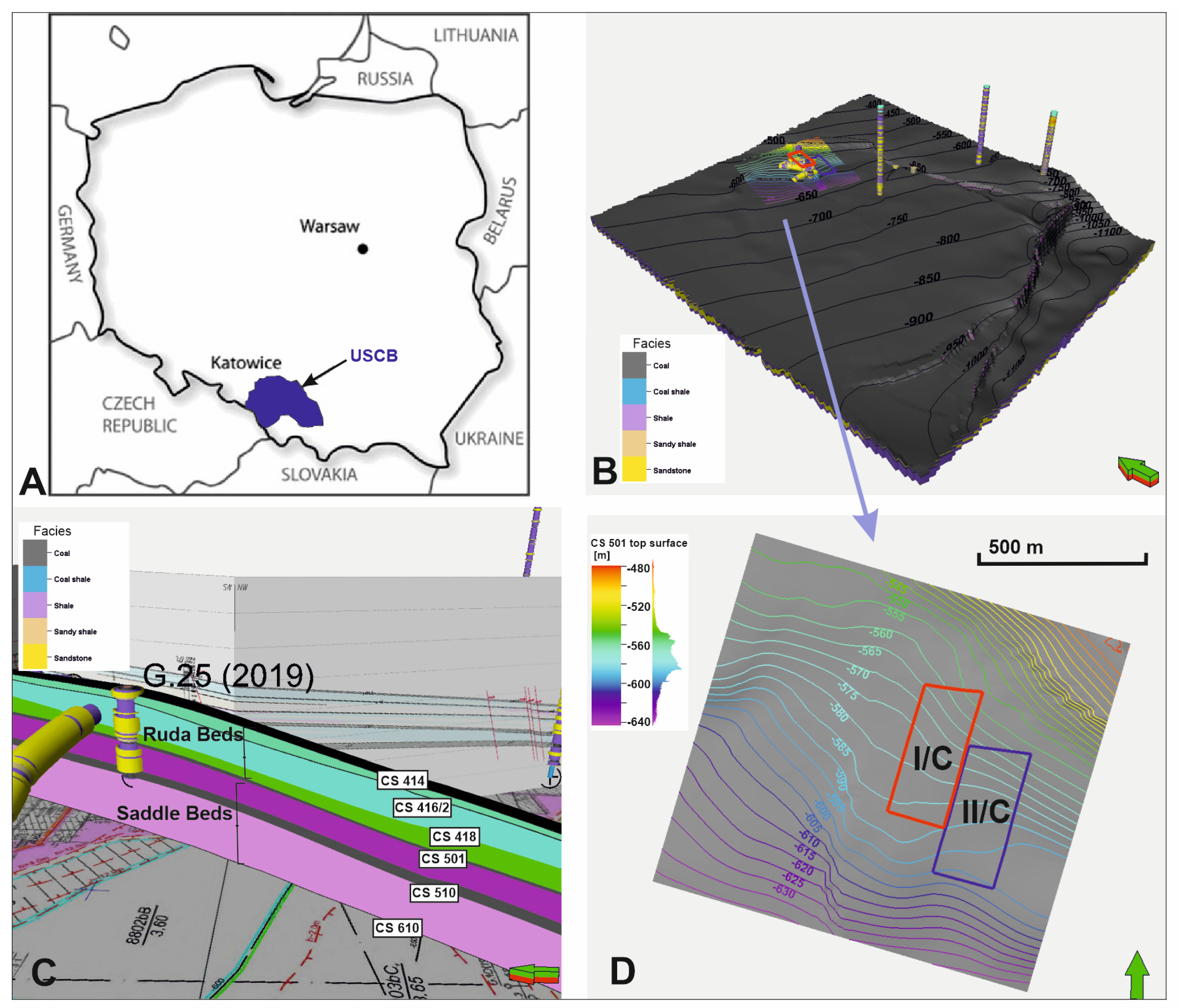
The area of the study is situated in the central part of the USCB (
Figure 1A). It is the largest coal basin in Poland and one of the largest in Europe, with favourable coalbed properties, including depths, relative thickness of coal seams, permeability and gas content. The USCB is located within the Upper Silesian Block, in the northeastern region of the Brunovistulicum Terrane [
38,
39,
40]. A characteristic feature of productive coal deposits within the carboniferous sediments in the USCB is their clear dichotomy. The older part of the profile consists of deposits formed in the conditions of paralic sedimentation with well-marked influences of periodic sea transgression. The upper part of the profile consists of younger deposits formed exclusively in terrestrial conditions, without sea influences, lying on paralic formations with a stratigraphic gap [
41]. In the study presented in this paper, the coal seam 501 of interest marks the top of the Siodłowe beds, belonging to the Upper Silesian Series and traditionally included in Namur B deposits. Siodłowe beds are developed mainly as thick-bedded sandstones interbedded with shales and mudstones, with multiple coal seams of the 500 group. Coal seam 501 in the area of the drainage and mining works, with a thickness ranging from 0.6 to 4.5 m, occurs at a depth ranging from approximately −480 to −610 m below sea level, due to strata inclination of 3°–10° in the southwest direction (
Figure 1B,C). The I/C and II/C coal panels, where the long directional drilling technology was tested are located within lot C, in the south-eastern part of the mine (
Figure 1D), which is delimited by natural boundaries—tectonic faults, from the northeast by the “Jakub fault”, from the west by the “Stanisław fault” and the boundaries of the mining area, from the south.
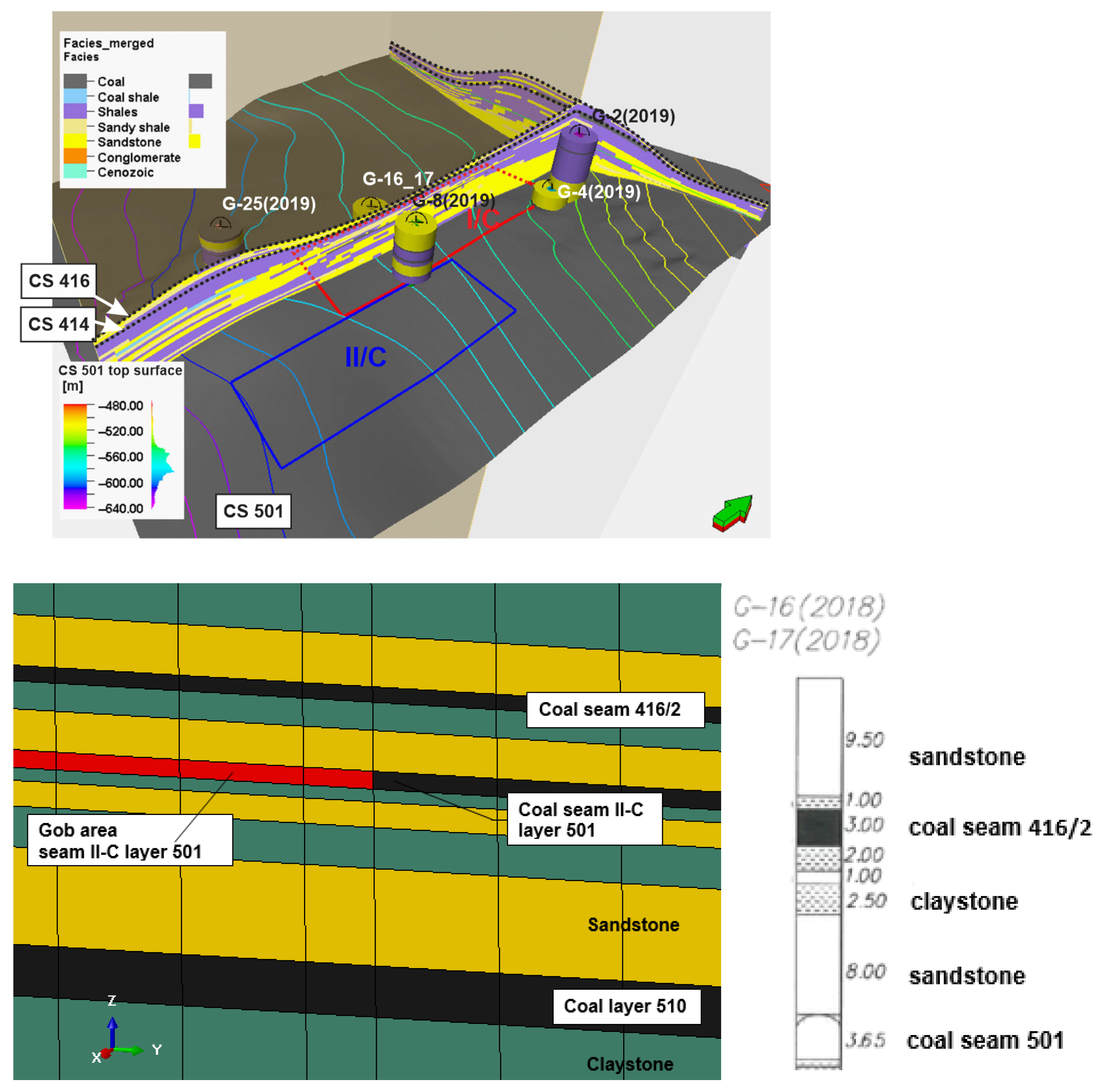
In lot C (Field C) of coal seam 501, coal panel exploitation was previously carried out with longwall I/C and, more recently, with longwall II/C. Coal panel II/C was designed at a depth of about 930 m and is being mined using a transverse roof collapse mining system, in a south-to-north direction, to a height of up to 3.4 m. The length of the mining front is about 160 m, and the planned runout of the longwall averages about 465 m. Different geological layers in the mining area (
Figure 2) have been identified through mining operations and boreholes. The coal seam 501 in this area mainly consists of a coal layer with a thickness of 3.05 m to 3.65 m, with an average thickness of 3.40 m. In the roof of the coal seam 501, sandstones with a thickness of up to 13.0 m occur in most of the area of the coal panel, while claystones with a thickness of up to 2.0 m occur in the southeastern part of the wall. In the bottom of coal seam 501 are claystones with a thickness of 6.10 to 9.50 m, and sandstones below them. There are also other deposits, such as deposit 416 above the floor of deposit 501 and deposit 510 below the floor of deposit 501 (
Figure 1C). There is a possibility of sedimentary disturbance in the form of sandstone intrusions into the floor of the coal seam 501, which may cause a reduction in the thickness of the seam, deflection of the seam, changes in the slope of the floor, and the presence of sandstone in the roof of the coal panel. In lot C, the exploitation of the coal seam 501 is carried out in an area where no other seams have been exploited up to more than 160 m above and below the coal seam 501. The disturbance of the rock mass in mining is relatively small.
Coal panels I/C and II/C were located at a depth of approximately 930 m. Above the coal seam, 3.5 m thick, there were layers of sandstone about 8 m thick, siltstone 2.5 m thick, sandstone 1 m thick and siltstone 2 m thick again, which formed the bottom of seam 416/2, 3 m thick. Even higher, above seam 416/2, were layers of sandstone of about 10 m and siltstone. The rock mass in this area is heterogeneous, with great variability in the stiffness of the individual layers.
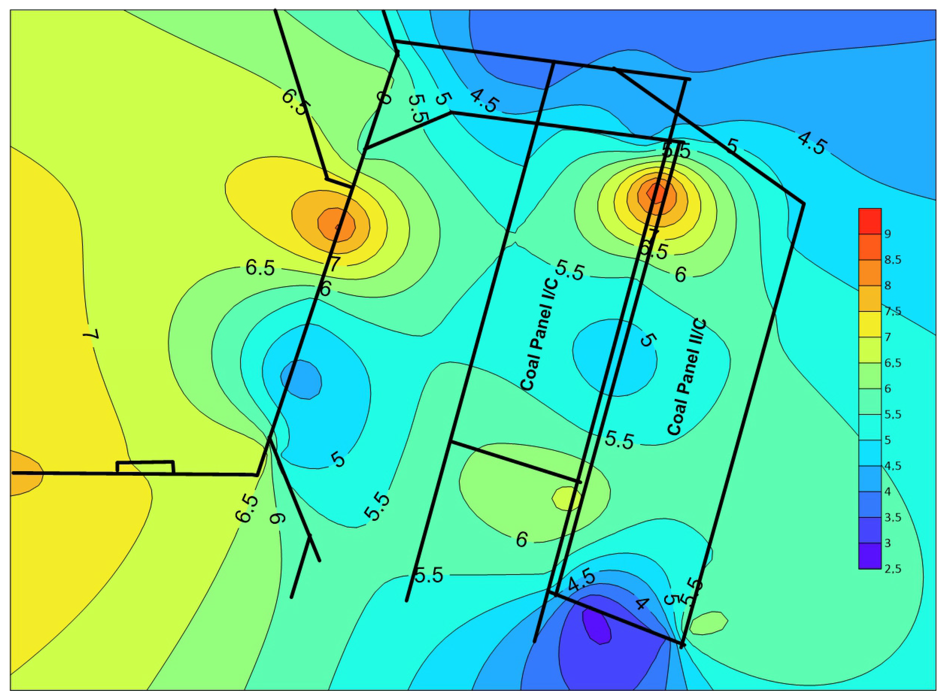
Despite the fact that the methane content of the coal seam, in the area of the preparatory works carried out in the coal seam 501, is a maximum of about 6.7 m
3CH
4/Mg
daf (dry ash free), the seam has been classified in the IV category of methane hazard according to Polish regulations. The average methane-bearing capacity in the entire coal panel ranges from 5.61 to 6.24 m
3CH
4/Mg
daf.
Figure 3 shows the isolines of methane content in the coal seam 501.
2.2. Methane Drainage Systems Applied
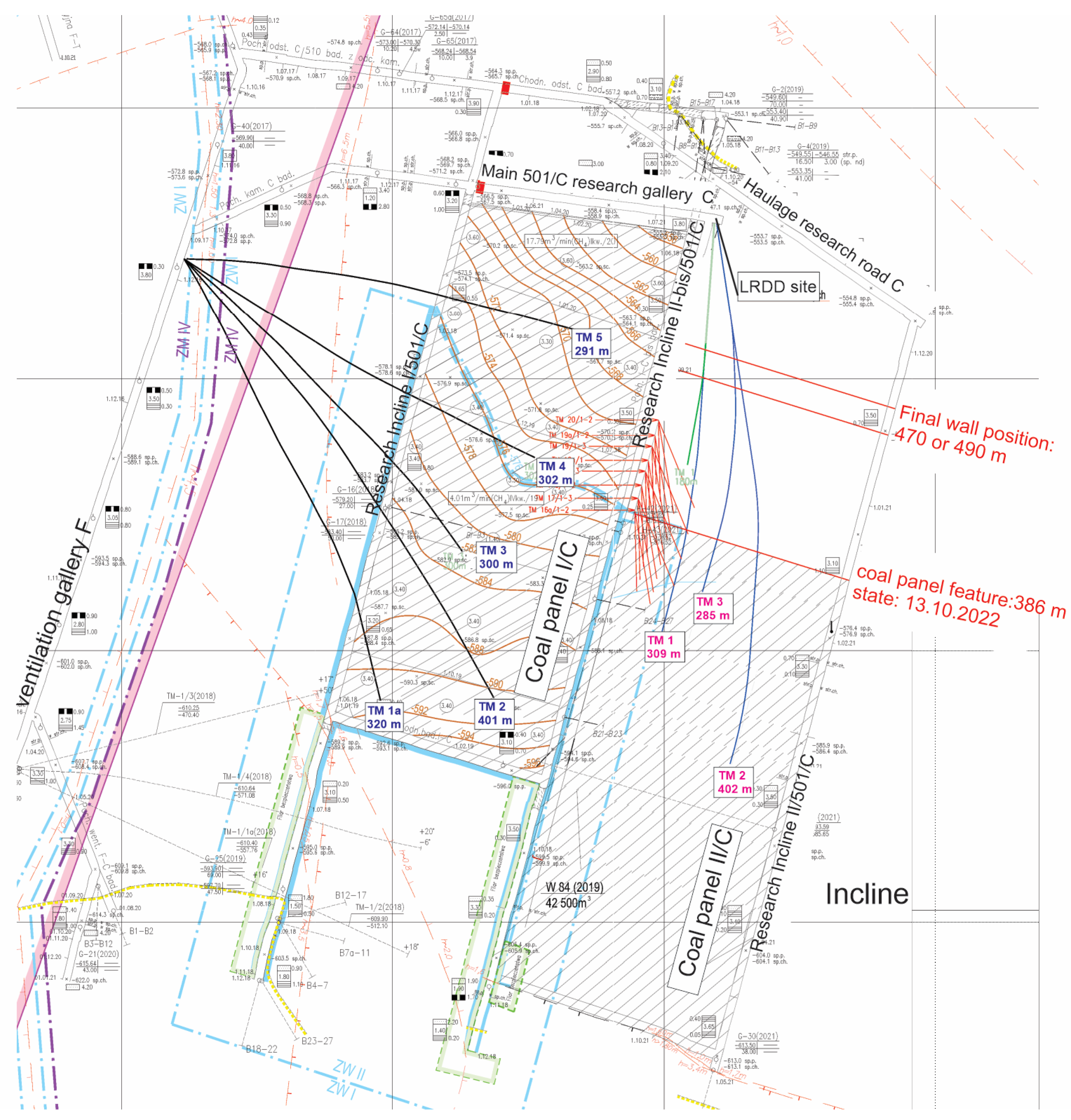
For the analyzed coal panel II/C workings in the coal seam 501, conventional methane drainage system was initially used from the road-heading galleries, and next, the directional boreholes and classical drainage boreholes located in the wall ramp. The methane drainage system was located under the depression of the surface drainage station, and the methane–air mixture from the methane boreholes was discharged via drainage pipelines. Due to the scale of the methane hazard, methane drainage was envisaged with three directional openings above the longwall excavation field of coal panel II/C. In addition, at a certain stage of the longwall run, five directional boreholes from the F ramp, which were made above the mining excavation of the previous coal panel I/C, were used. The 5 horizontal wells were drilled from the ventilation gallery F to access the clay/sandstone layers deposited above the 501 coal seam. The lengths of well segments laying above the coal bed 501 were approximately equal to: 53 m (TM-2), 26 m (TM-4), 32 m (TM-3) and 35 m (TM-5). The total lengths of the horizontal wells were much greater and amounted to 355 m (TM-2), 320 m (TM-3), 290 m (TM-4) and 295 m (TM-5), respectively. We assumed that the flow of methane to these horizontal wells from the coal bed and sandstone/siltstone layers overlying the coal strata, took place only to the well segments lying directly above the coal seam. The arrangement of directional wells drilled for the methane drainage purposes from inclined gallery F (deck 501, level 900) and the trajectories of these wells (TM-1 to TM-5) are shown in
Figure 4.
2.3. Mining and Ventilation Setting
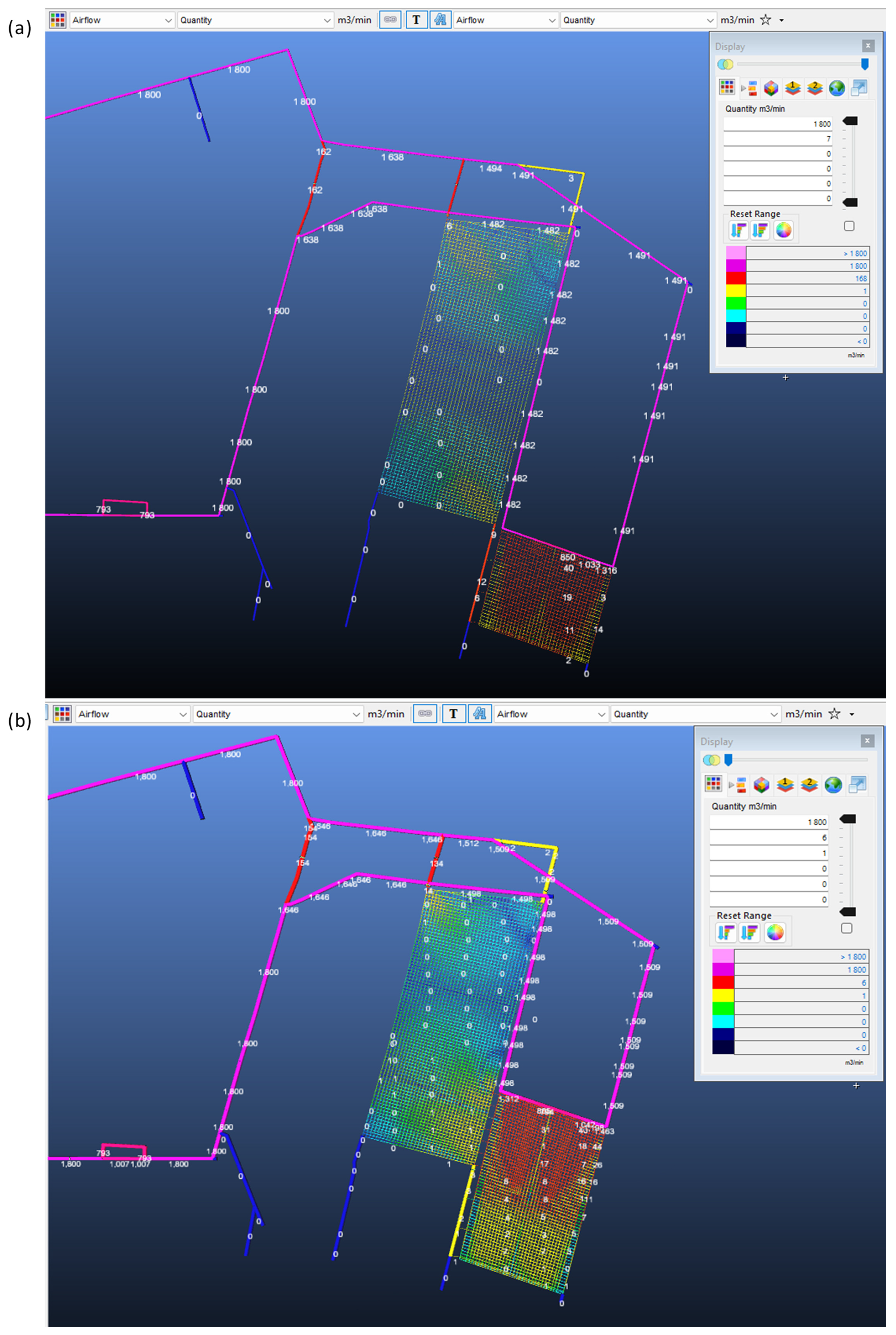
Ventilation of the mining area of coal panel II/C is performed, taking into account the co-occurring methane, fire, and rock outburst hazards in order to ensure the safety of the staff. The ventilation scheme is shown in
Figure 5a,b with the details of the depth of the excavations and the colours illustrating the deposition of the coal seam 501 produced with the use of the Ventsim—3D Mine Ventilation Design software version 4.0.9.9.
The results of airflow in the workings are presented for two stages: before the merging of the mining goafs of the I/C and II/C coal panels (
Figure 5a) and after the merging of the mining goafs (
Figure 5b). For the stages taken in this way, an analysis of the airflow and depressional relations in the area of the ongoing mining of coal panel II/C can be made.
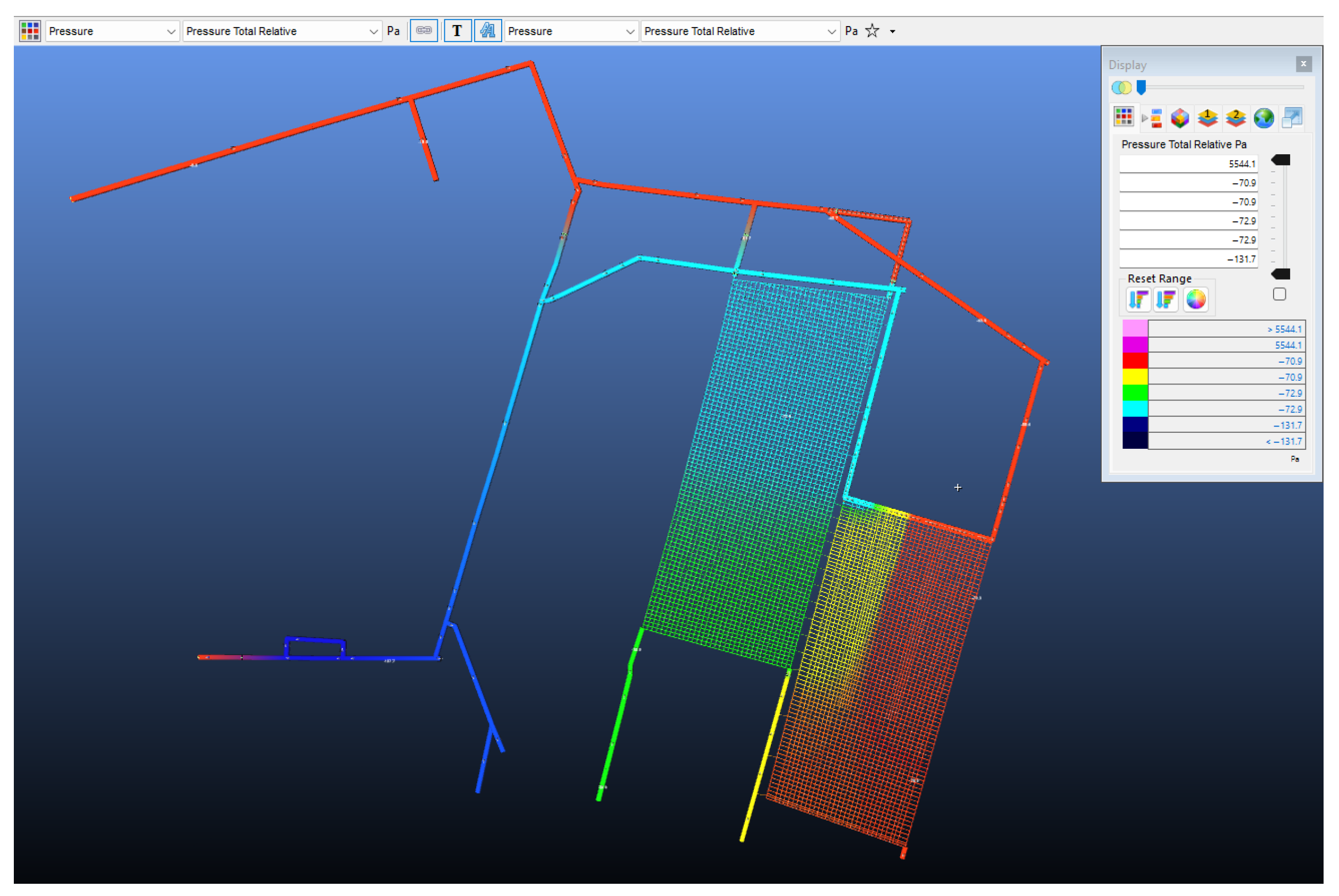
Figure 6 shows the pressure distribution in the workings and goafs in the area of longwall II/C, which indicates the directions of migration of the air–methane mixture.
2.4. Sorption Kinetics Measurements
Methane sorption kinetics were determined to support the interpretation of methane emission behaviour and the performance of the methane drainage system under varying geo-mechanical and ventilation conditions. Laboratory measurements were conducted on ten coal samples collected from the gallery in coal seam 501 in the vicinity of longwall II/C using the IGA-001 gravimetric sorption system (Hiden Isochema, Livonia, MI, USA). The analysis focused on parameters describing methane storage and release characteristics of coal, including the effective diffusion coefficient (De), sorption capacity with respect to pure carbonaceous matter (adaf), and half sorption time (t1/2).
The sorption capacity (a
daf) ranged from 2.420 to 2.689 cm
3/g
daf, indicating relatively uniform methane storage potential across the analyzed samples and suggesting a comparable pore structure of the coal matrix within the study area. The effective diffusion coefficient (D
e) varied between 0.097 × 10
−8 and 0.247 × 10
−8 cm
2/s, reflecting differences in methane transport rates within the coal structure. Higher D
e values indicate faster methane desorption and may be associated with structural heterogeneities of coal or the influence of nearby geological disturbances [
42]. The half sorption time (t
1/2) ranged from 1571 to 4011 s, further illustrating variability in methane release dynamics between individual samples.
All sorption parameters were determined under equilibrium conditions at a pressure of 0.1 MPa. The obtained values provide quantitative input for assessing the potential contribution of coal properties to observed variations in methane emission intensity and drainage efficiency. In combination with geo-mechanical modelling and ventilation analysis, the sorption kinetics results support a more comprehensive, decision-oriented evaluation of methane migration pathways and the effectiveness of methane drainage strategies applied in deep underground coal mining.
The methane drainage performance observed in the analyzed longwall panel is closely linked to the kinetics of methane desorption from the coal matrix. Methane in coal seams is predominantly stored in the adsorbed phase and its release during mining is initiated by a pressure drop resulting from mining-induced stress redistribution. The sorption measurements performed for coal seam 501 indicate relatively uniform methane storage capacity (adaf = 2.420–2.689 cm3/gdaf), suggesting that the total methane resource available for release is spatially consistent across the analyzed area. However, the variability in effective diffusion coefficients (De = 0.097–0.247 × 10⁻⁸ cm2/s) and half sorption times (t1/2 = 1571–4011 s) indicates differences in the rate at which methane can desorb and migrate from the coal matrix into the fracture network. Higher diffusion coefficients correspond to faster methane desorption and therefore to a more rapid supply of methane to the fracture system and drainage boreholes once pressure decreases in the stress-relief zone.
This relationship helps explain the observed variability in methane capture efficiency during the different stages of longwall mining. In the early phase of panel II/C extraction, when fracture permeability in the roof strata increased and pressure gradients directed gas flow toward the directional boreholes, methane released relatively quickly from the coal matrix could be effectively captured by the drainage system. As mining progressed and the fracture network expanded, particularly after the hydraulic connection of goafs from panels I/C and II/C, methane migration pathways became controlled primarily by large-scale pressure gradients within the fractured rock mass. Under these conditions, although methane desorption from the coal matrix continued, a larger portion of the released gas migrated toward the interconnected goaf zones rather than toward the directional boreholes, resulting in a reduction in drainage efficiency. Thus, sorption kinetics primarily govern the rate of methane release, while the geo-mechanically controlled fracture system and pressure field determine the effectiveness of methane capture by the drainage system.
3. Results
3.1. Methane Emission
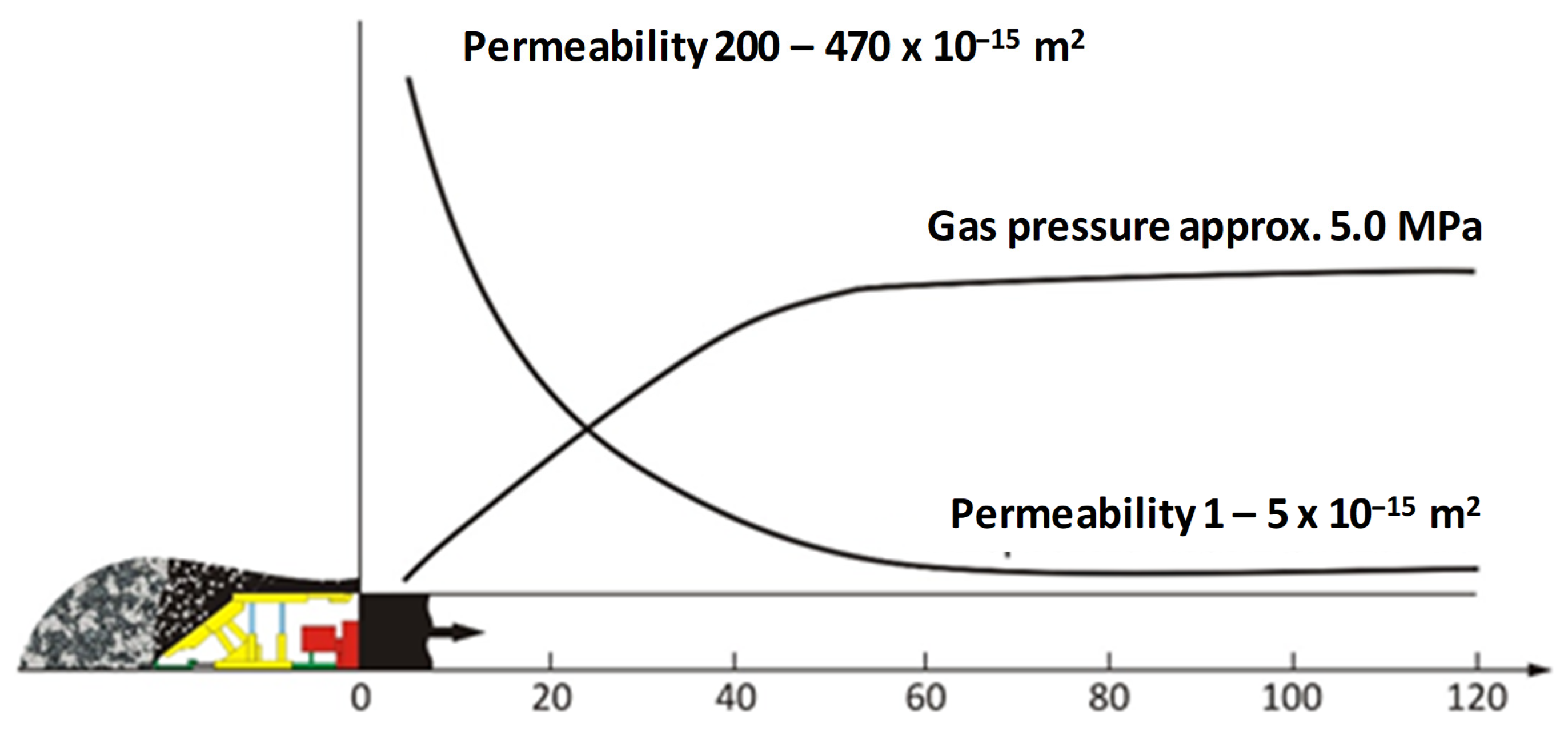
The coal seam extraction causes relaxation and cracking of the coal seam and the overlying and underlying rocks. This results in a multiple increase in the permeability of the rock in the fracture zone around the mining operation, which enables a relatively free flow of methane from the de-stressed zone into the longwall workings. The pressure gradient that occurs causes a movement of the gas mass towards the workings, where the pressure is lower than the pressure of the gas contained in the rock mass. The distribution of pressure changes into the rock mass is an unstable and spatial process. The nature of methane release into mine workings is complex, as it depends on several geological and mining factors further characterized below. Methane is released from the coal seam, from the longwall face, into the longwall workings through the system of fractures. In addition, it also flows through fractures and cracks in the rock mass surrounding the workings from adjacent coal seams that have been partially stress-relieved by mining. The observations to date allow two main forms of methane release into the mine workings to be distinguished: (i) desorption and filtration flow of methane under the influence of the pressure gradient caused by mining operations, and (ii) methane flows out of fractures and cracks in the seam, formed in the layer adjacent to the coal face due to changes in the pressure distribution between the media. The phenomena of desorption and simultaneous filtration are closely related to each other in both mechanical and energetic terms (thermodynamic transformation). Depending on the conditions, the rate of gas release is determined by the rock mass’s desorption rate and the permeability. The value of the permeability coefficient is influenced by the rock mass pressure associated with the exploitation, and changes over time and in the seam space. Changes in permeability and gas pressure in the coal seam ahead of the longwall face are shown in
Figure 7. The highest permeability of the coal seam occurs at the longwall face and decreases with distance from the longwall face to a constant value, which corresponds to the conditions of an undisturbed coal seam. The gas pressure in the seam is lowest at the face of the longwall and increases deeper into the seam.
As seen, the methane release from the coal seam not stressed by exploitation will be minor. Only in the zones of tectonic disturbances can there be de-stressed zones with increased permeability and fracturing, where the release of methane will be intense. The largest proportion of methane will be released during mining operations after the rock mass has been relaxed, when good conditions for methane filtration have been created. Then, due to the relaxation, the pore and fracture volumes increase, the saturation pressure in the coal seam decreases and the conditions for methane release exist. Coal seam permeability is one of the most important parameters that can affect the flow of gas in a coal seam. This can directly affect the effectiveness by borehole drainage. The stresses of the surrounding rock in coal seams can alter the distribution of their permeability. At the same time, methane pressure can also affect the effective distribution of stresses in the coal seam, so it also affects the deformation of the coal layers. Thus, a coupled interaction exists between coal rock stress and methane permeability. A statistical analysis of methane release and capture is presented below.
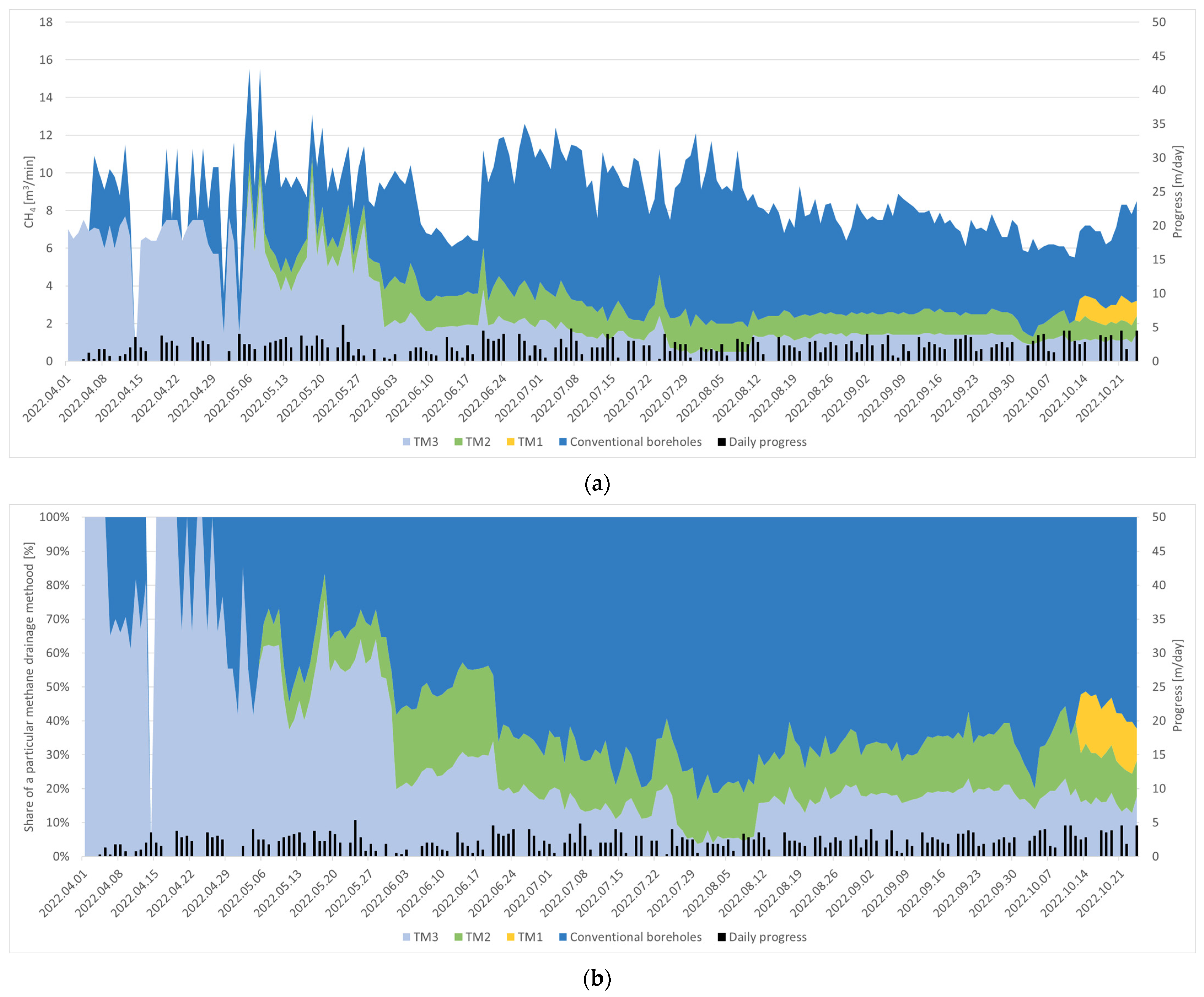
Figure 8a shows the capture of methane from the drainage system at the longwall runway, and
Figure 8b the cumulative values of captured methane from the coal field II/C.
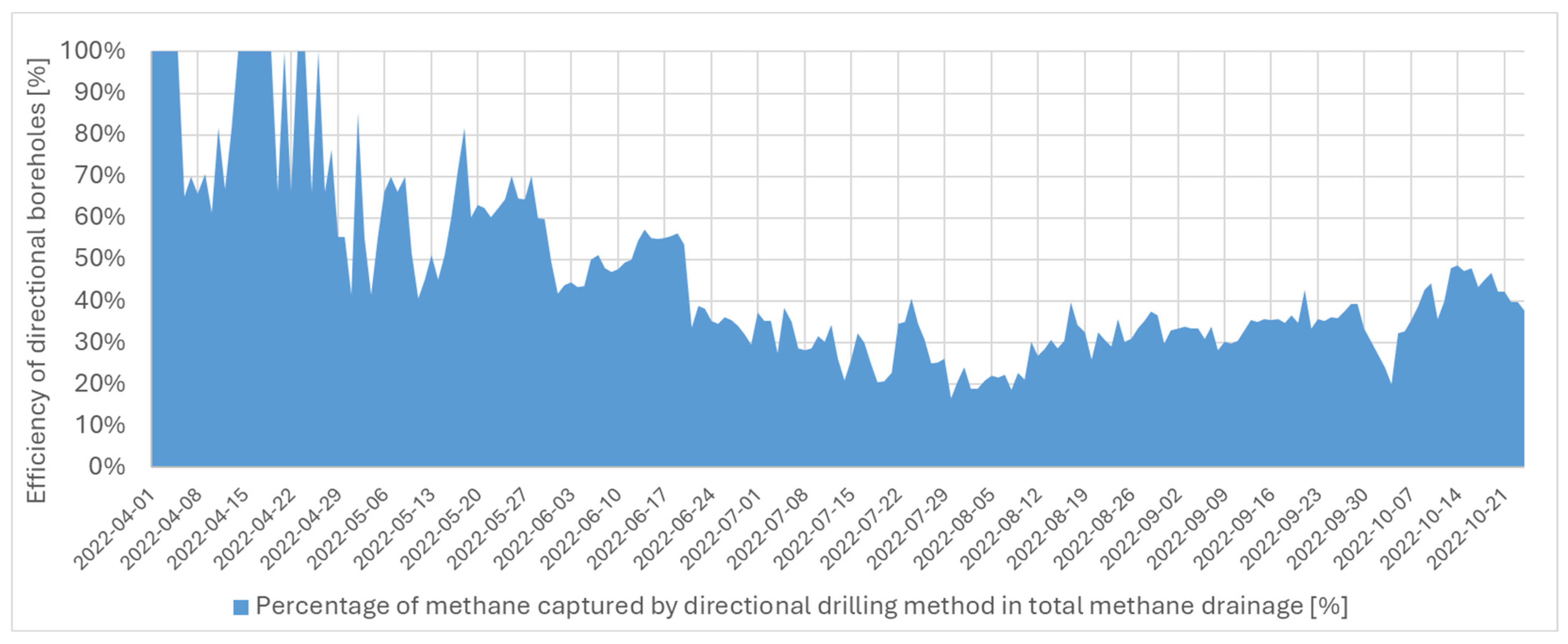
In the initial mining phase—in the early part of the longwall run, the largest amount of methane was discharged through borehole TM-3. Only in the middle of the longwall run, when a significant goaf space had been created, the shares of methane intake from directional boreholes and classic methane drainage became equal. In July 2022, the coal panel II/C run reached the height of where coal panel I started, which resulted in merging the goafs of both panels. As a result, the efficiency of methane capture from directional boreholes decreased.
Figure 9 shows the percentage change in the share of methane intake through directional boreholes in relation to total methane drainage from the coal panel II/C field. In April 2022, the share ranged from 70 to 100%, fluctuated at 60% in May and was 50% in June. In the following months, it remained at 30%. The analysis of the results indicates a high variability in the methane capture, which is due to the development of flows in the caving zone of the exploited coal panel and changes in depressional relations related to connections with the goaf of the neighbouring coal panel I/C.
3.2. Geo-Mechanical Conditions for the Location of Methane Drainage Boreholes Based on FEM Numerical Modelling
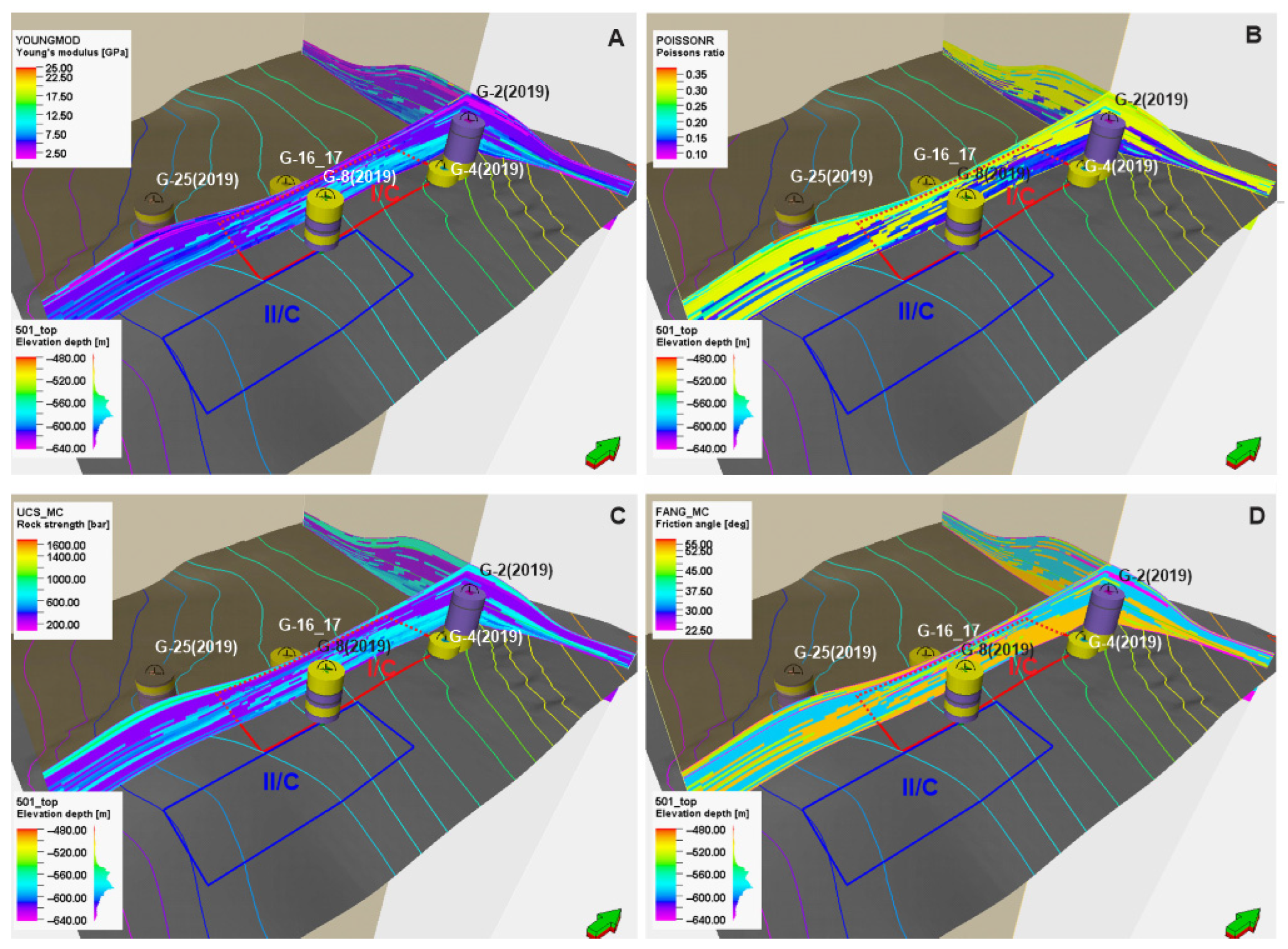
The stress relief zone, where methane is primarily desorbed from the coal due to effective stress reduction and the activation of the fracture network, is fundamentally controlled by the geo-mechanical conditions of the surrounding rock mass. The rock mass around the analyzed coal panels is heterogeneous, with great variability in the stiffness of the individual layers. To characterize the mechanical behaviour controlling rock response during coal extraction in panels I/C and for optimization of borehole placement draining coal panel II/C, data on key geo-mechanical parameters—including Young’s modulus, Poisson’s ratio, unconfined compressive strength (UCS), and friction angle—were integrated from archival reports, digitized, and modelled. These parameters are presented as three-dimensional distributions in the vicinity of the excavated panels in
Figure 10A–D.
The principal objective of geo-mechanical analyses was to indicate regions of the rock mass, where mining induced deformation cause overstressing and damaged zones occurrence resulting in additional cracking of the rock mass. It should be noted that conditions favourable to methane migration in the cracked zone only apply to regions experiencing tensile stresses, or close to such, and shear stresses causing shearing of existing cracks [
33,
37,
43]. Such stresses activate the discontinuity network and allow or facilitate methane migration to the drainage boreholes.
To assess the zones affected with coal panel movement, geo-mechanical simulation was carried out using the Visage Finite Element Method geo-mechanical simulator (SLB). The initial stress distribution was calculated by integrating the regional tectonic stress field, interpreted from borehole damage zones stress direction and literature, with the gravitational load of the overburden [
44]. These boundary conditions were applied to spatial models incorporating the geo-mechanical and petrophysical properties to calculate the stress field and coupled with fluid flow models and accounting for historical excavation across multiple coal seams, with the primary focus on coal panel I/C [
44]. Although coupled models were performed fully for coal panel I/C, the resulting stress disturbances patterns and the geometry of fractured zones is considered to be representative and valuable for the rock response in the adjacent coal panel II/C and serve for the interpretation of drainage borehole placement and its draining performance.
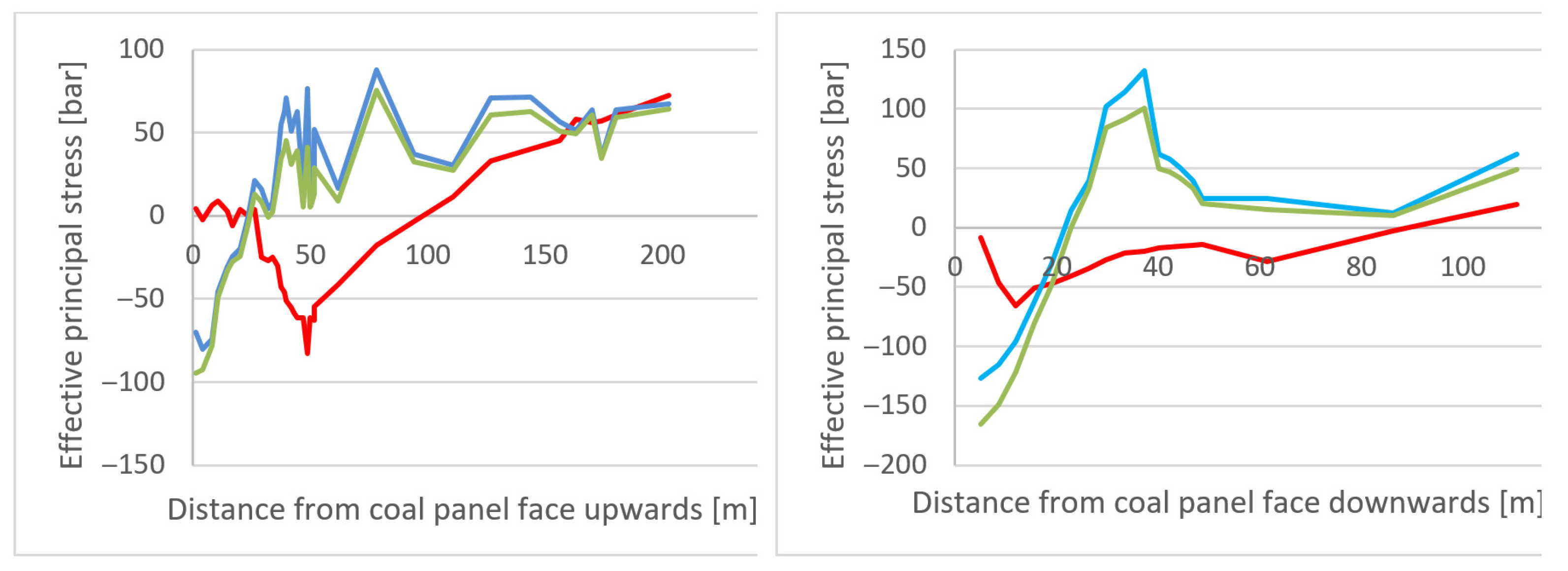
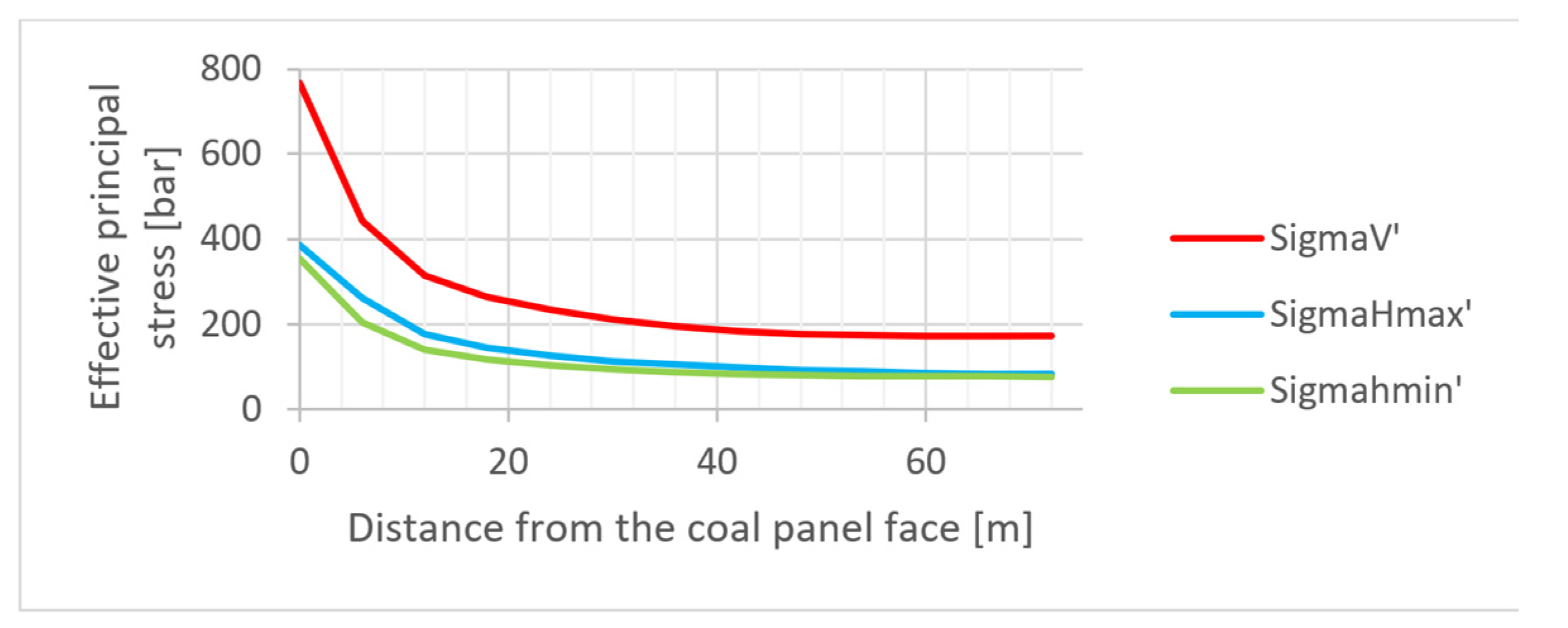
Simulation results indicate a concentration of all principal stresses—effective vertical, minimum horizontal and maximum horizontal stress right ahead the coal panel I/C face, with a diminishing perturbation trend as the distance to the coal panel increases. Stress perturbations are most pronounced in vertical stress distribution, which significantly deviates from the virgin, unmined state. This stress redistribution is consistent with observation widely reported in the literature for coal panels extraction [
45] and is visualized in
Figure 11, where effective vertical stress is marked with a solid red line.
In the vertical direction, the stress relief zone affects a more considerable volume of rock than in the horizontal plane. Vertical stress relief extends approximately 60 m below and 160 m above the coal panel face.
In the case of principal horizontal stress, the affected zone is smaller, reaching approximately 120 m upwards and 50 m in the strata below the excavation (blue and green lines in
Figure 11). In the horizontal plane, stress distributions for all principal stresses remains undisturbed at the approximately 55 m from the coal panel face (
Figure 12).
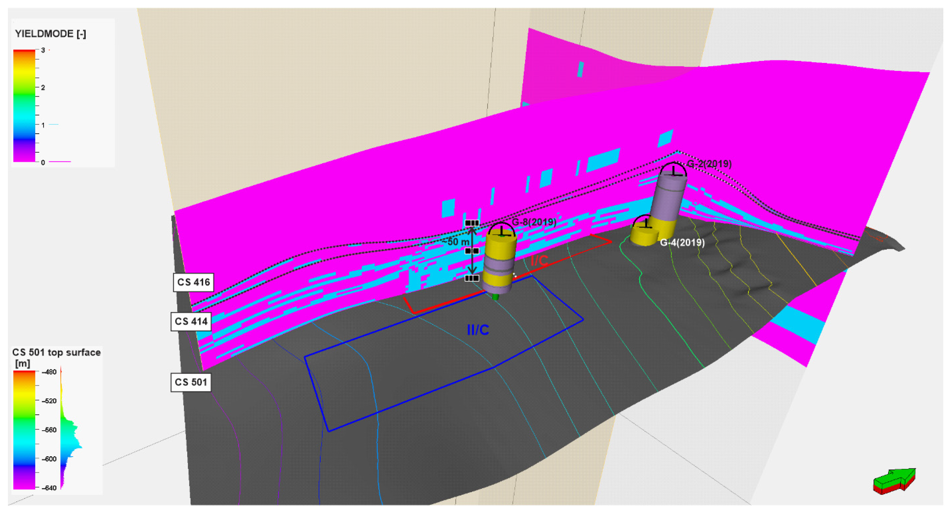
The results obtained for the advanced stage of mining of coal panel I/C (half excavation) indicate the development of fracture zones above the direct caving area, primarily within the sandstone layers lying between coal seam 501 and 416/2 and to a limited extent in a higher-lying sandy shale layers, marked with blue where the tensile zone occurred (
Figure 13). The formation of these fractures promotes block separation within the rock mass and creates additional pathways for methane migration. Consequently, from a geo-mechanical perspective, the sandstone layer and overlying sandy shales within approximately 50 m above coal seam 501 were identified as the most favourable horizons for drilling methane drainage boreholes above the coal panel II/C.
Methane drainage of coal panel II/C in seam 501 was carried out through three boreholes drilled into the roof (
Figure 4). Drainage efficiency was variable and showed a strong dependence on the spatial relationship between the advancing coal panel II/C face and the old goafs of the previously excavated coal panel I/C. Drainage efficiency decreased considerably once the front of coal panel II/C aligned with the goafs of coal panel I/C.
Although numerical simulations were carried out for coal panel I/C only, nevertheless drawing on the stress redistribution patterns and fracture zone geometry established for panel I/C, a geomechanical interpretation of the observed drainage efficiency decline is proposed. It is reasonable to assume that as the II/C longwall face approached alignment with the goafs of coal panel I/C, intensive damage and fracturing developed in the corner zones of the two interacting goaf areas. This would likely have resulted in the formation of a connected fracture zone between the goafs of panels I/C and II/C, extending through both the sandstone layer above seam 501 and the siltstone layer between seams 501 and 416/2—the same horizons identified as the primary fracture pathways in the panel I/C model. Under such conditions, methane would be expected to migrate preferentially into the old goafs of coal panel I/C rather than toward the drainage boreholes installed above panel II/C, which would account for the observed reduction in drainage efficiency. These findings highlight the importance of accounting for goaf interaction effects in the design and adaptive placement of methane drainage boreholes during sequential longwall mining operations, and motivate future fully coupled numerical modelling of interacting panels.
3.3. Ventilation, Emissions and the Capture of Methane by a Drainage System
Assessment of methane drainage efficiency with classic CM (Cross Measure) and LRDD borehole systems.
At the “Staszic–Wujek” Coal Mine, longwalls I/C and II/C exploited the 501 coal seam and were ventilated with a “U” system with air flowing across the longwall face via the intake gate road, and the return air via the return gate road. A combined methane drainage system was used for both longwall panels consisting of LRDD and CM boreholes. The CM boreholes were installed in an overlapping fashion to maintain a continuous low-pressure zone to control gas emissions and maintain permissible methane limits in the proximity of and out by of the intersection of the longwall face and the return gate road. In addition to the CM boreholes, two different variants of LRDD boreholes were implemented. Five LRDD boreholes were drilled perpendicular to the I/C longwall panel from a ventilation roadway approximately 190 m west of the longwall panel. The limitation of suitable sites for directional drilling dictated this configuration. For longwall II/C, three LRDD boreholes were drilled parallel to the longitudinal axis of the longwall panel, which is the orientation applied globally.
The total length of all LRDD boreholes for the I/C coal panel was 1675 m, and for II/C was 996 m.
Although implemented in conjunction with CM boreholes, the effectiveness of the LRDD boreholes was successfully demonstrated. More methane was captured during active longwall mining, and methane concentrations at the longwall face and return gate road intersection were measured at reduced levels. Because the LRDD boreholes could be produced after the completion of mining, the LRDD boreholes placed over Longwall I/C provided benefits during longwall mining of the adjacent Longwall II/C because of connectivity across both goaf areas. Measurements of the methane concentration of the gas recovered from each LRDD borehole suggest that high methane concentrations can be captured with this system.
Table 1 presents the average methane concentration achieved by the individual LRDD boreholes TM1-TM5 for longwall I/C. The average methane concentration of the gas recovered by all five LRDD boreholes was 77%.
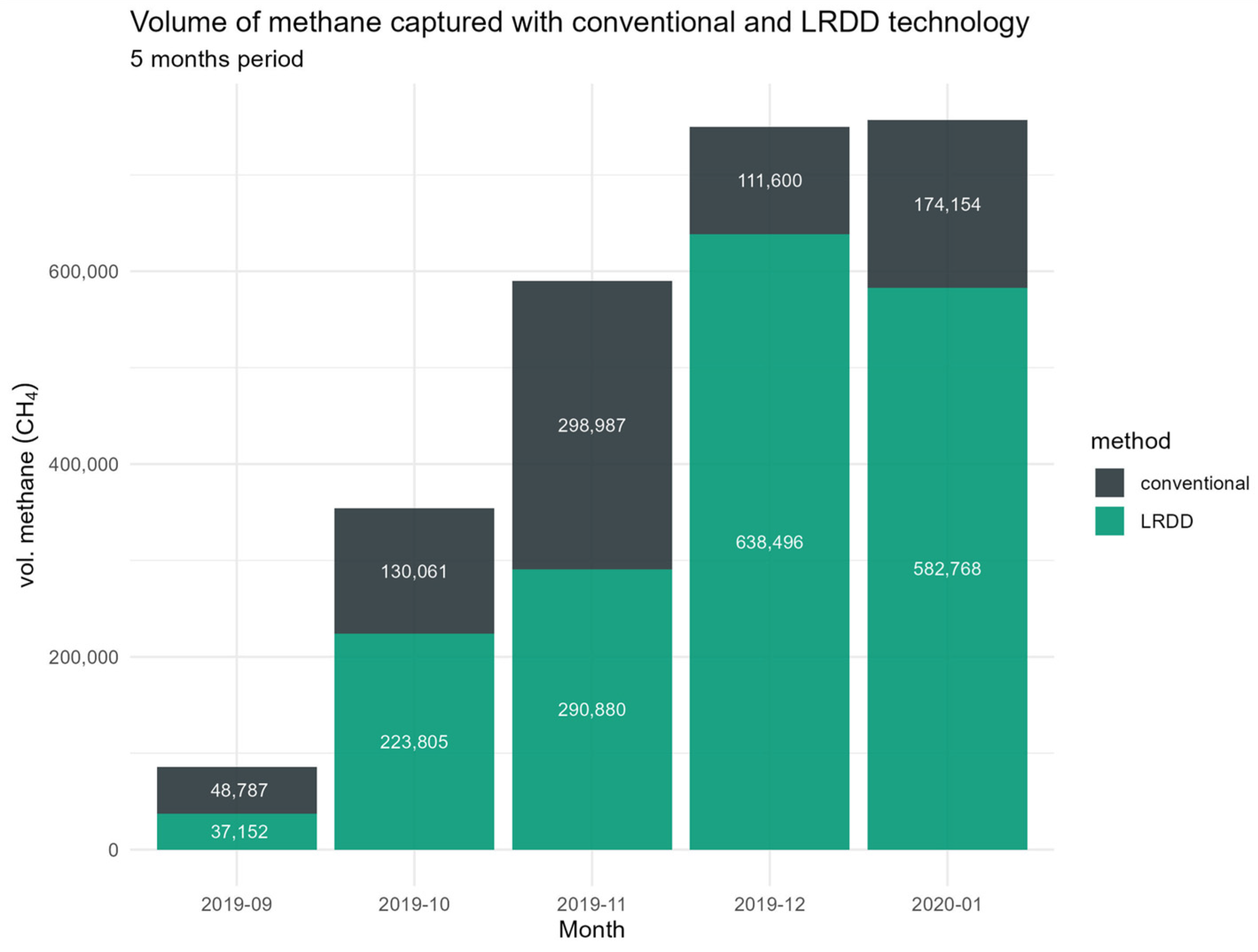
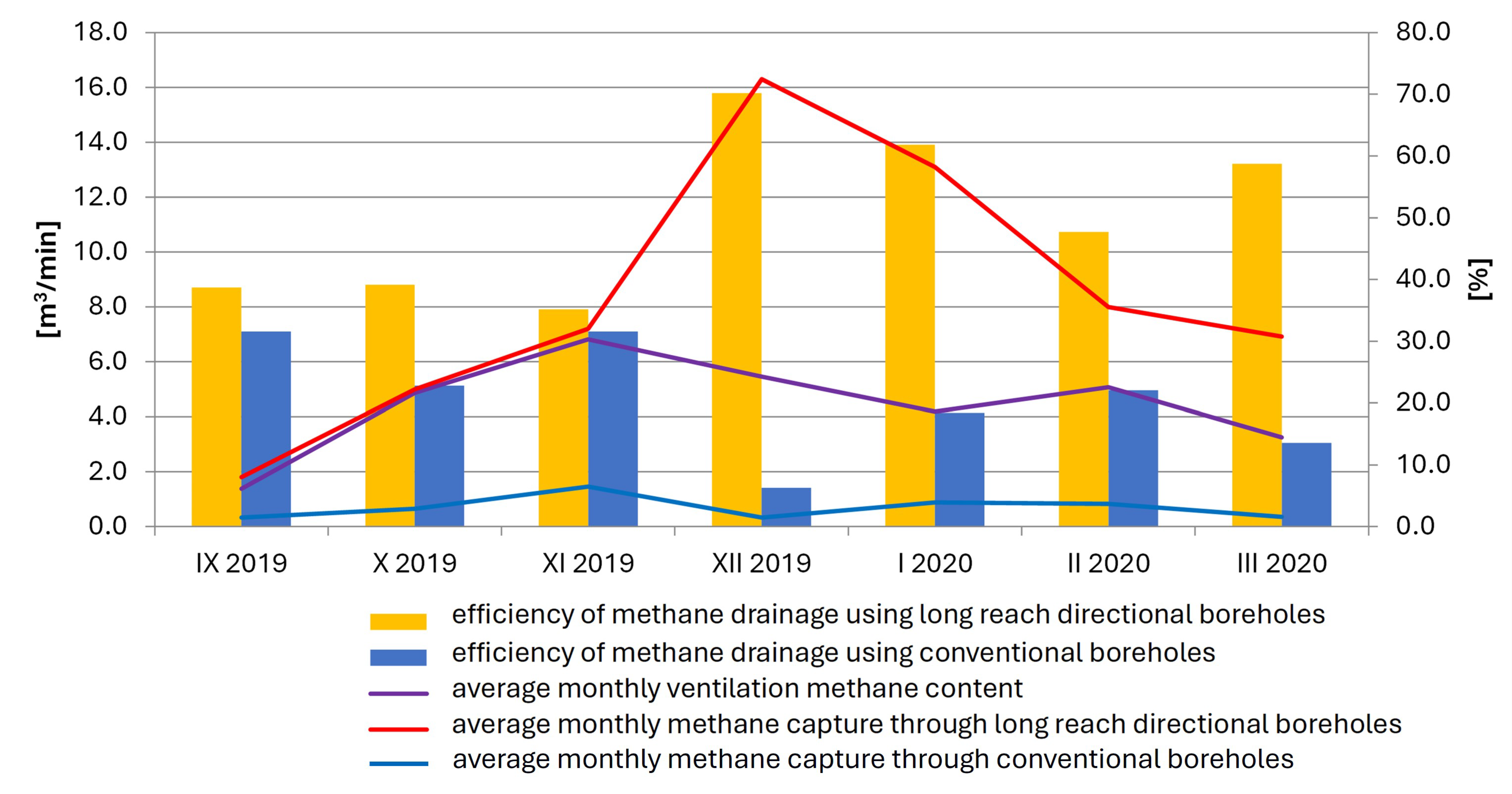
The volume of methane captured, efficiency with conventional CM and LRDD technology on I/C panel, and aggrageted effectiveness of methane drainage is shown below (
Figure 14,
Figure 15 and
Figure 16).
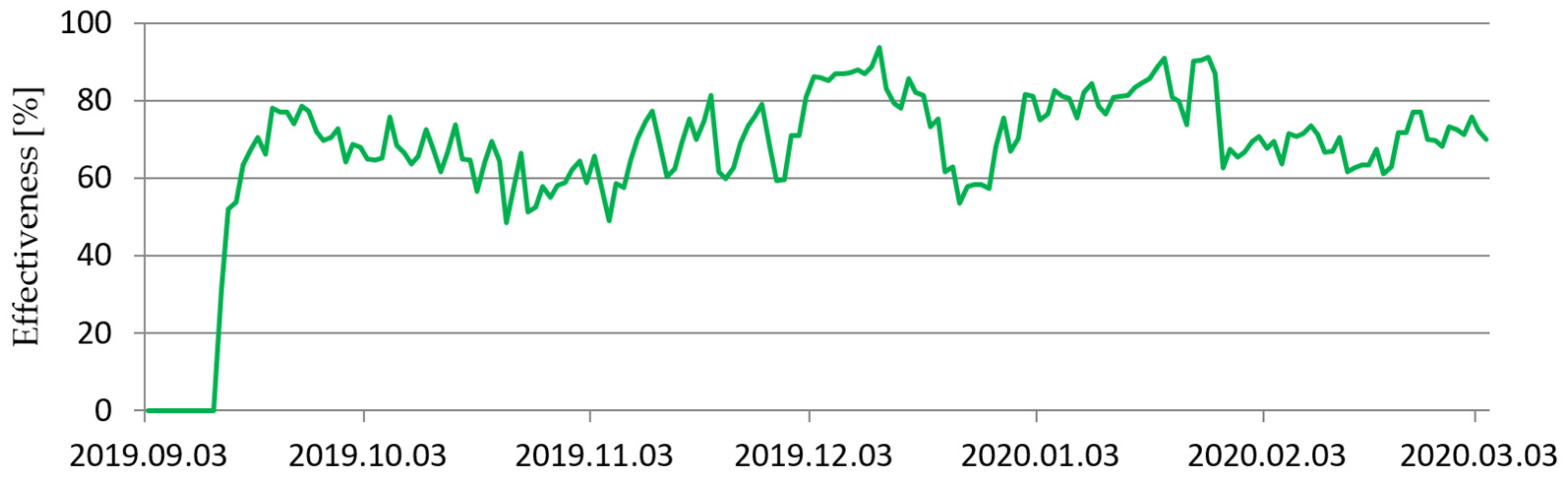
The average daily methane drainage aggregate effectiveness in coal panel I/C in the period of September 2019–March 2020 was 71% and the max. was 94%.
To summarize the results of methane drainage effectiveness in the panel I/C, it should be noted that:
Conventional (CM) boreholes: 763,588.8 m3 CH4 (30.1%);
LRDD boreholes: 1,773,100.8 m3 CH4 (69.9%);
SUM: 2,536,689.6 m3 CH4 (100%).
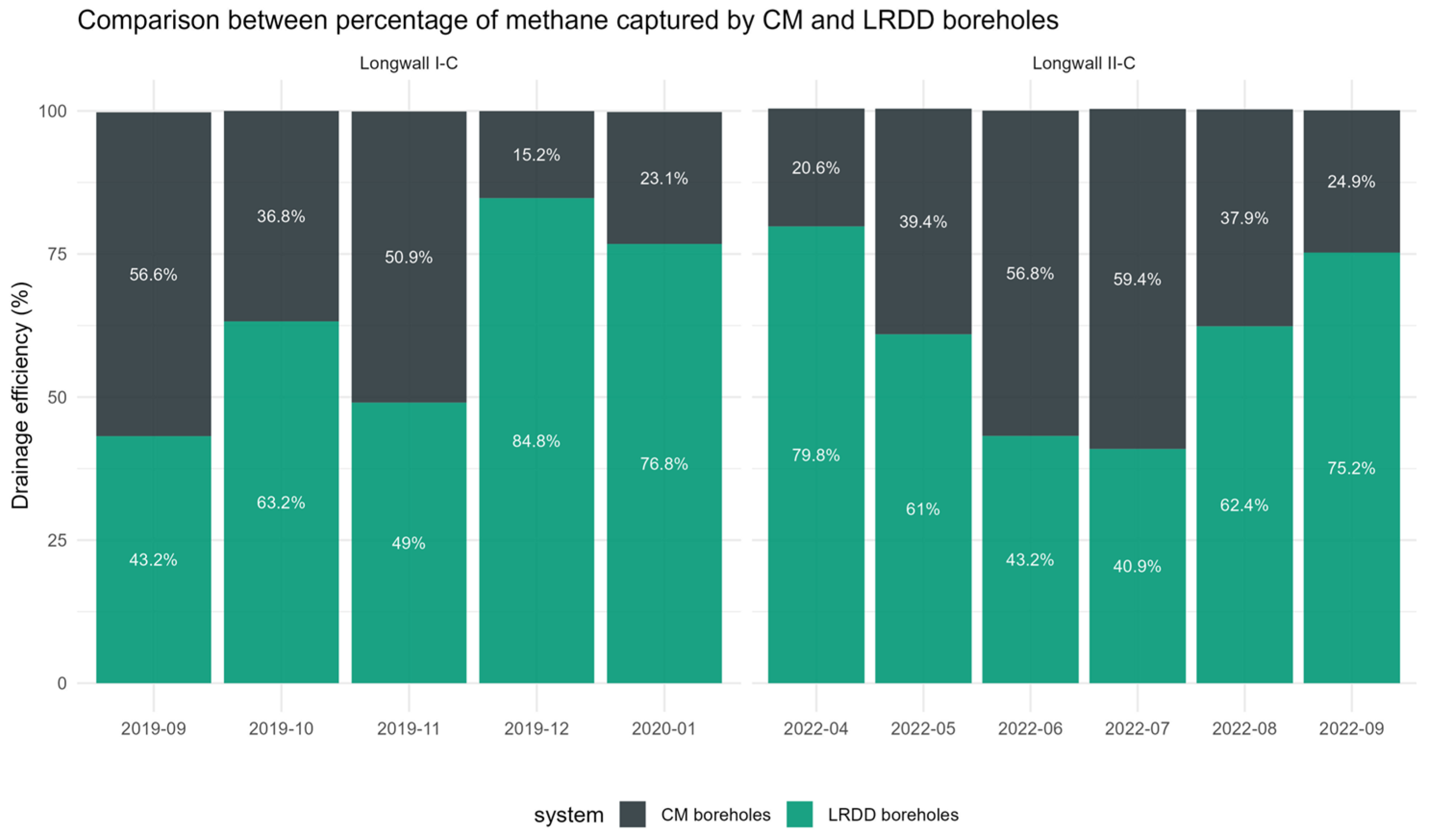
The comparison of the percentage of methane captured by CM and LRDD boreholes for coal panels (I/C and II/C) was shown below in
Figure 17.
As for the total volume of methane recovered by each of the two systems for longwall I/C, the LRDD boreholes recovered 63% of the total methane captured. In contrast, the CMboreholes recovered 37%. The measured methane flow rates for the CM boreholes (average of 3.75 m
3/min) and the LRDD boreholes (average of 8.6 m
3/min) during the mining of longwall I/C (more information available in research paper Leśniak 2022—references [
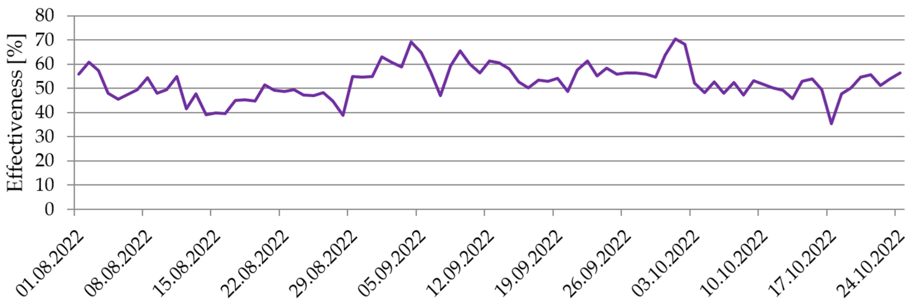
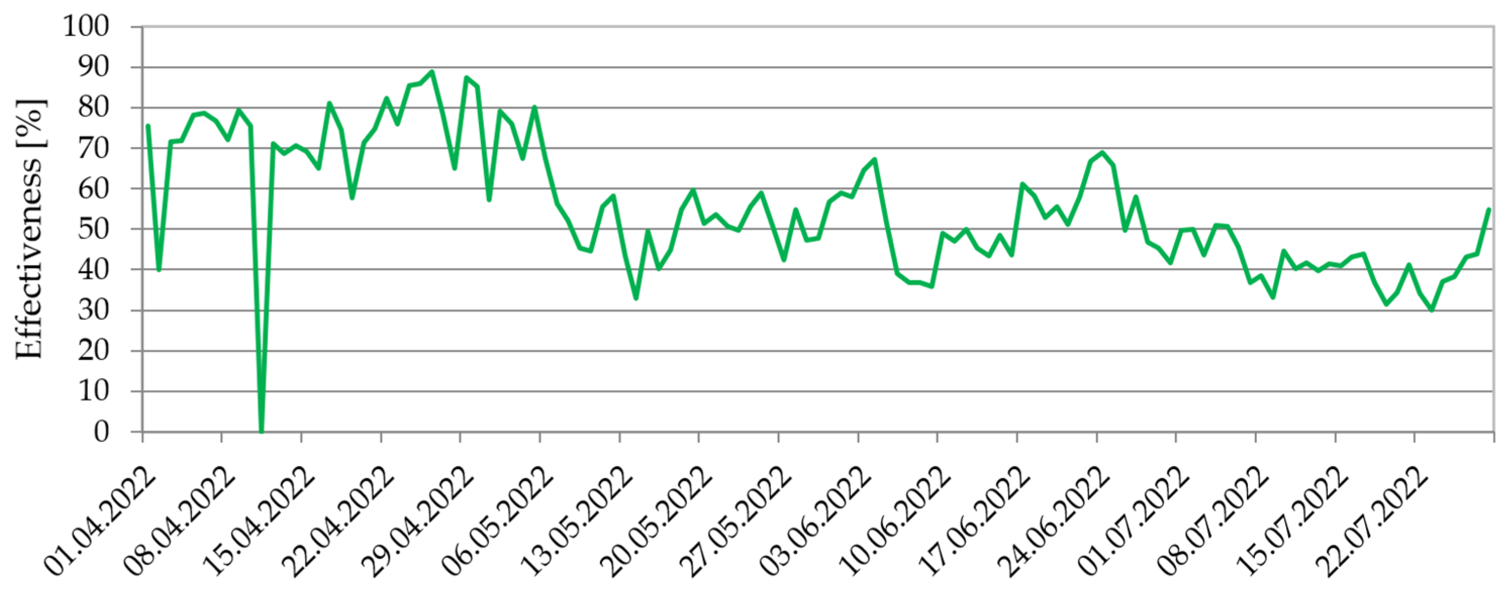
10]). During the mining of longwall II/C, the percent of methane captured by the three LRDD boreholes was also high and close to 60% over the longwall mining period. The methane drainage efficiency of the CM borehole system alone is estimated to be between 25 and 30%. Combined with LRDD boreholes, the results of the DD-MET study suggest that a combined system of CM and LRDD boreholes can capture between 50 and 60% of the total methane released from an active longwall panel. In the coal panel II/C, from April to October 2022, methane drainage was conducted using classic CM and LRDD boreholes. The effectiveness results are presented on graphs below (
Figure 18 and
Figure 19, respectively), divided into two periods (April–July and August–October 2022).
The analysis of measurement data revealed distinct differences in the effectiveness of the applied methane capture systems, particularly in the case of directional boreholes drilled above coal panel II/C. During the initial phase of mining, directional borehole TM-3 contributed the highest share of methane capture. As mining progressed and the goaf of longwall II/C expanded, the relative contribution of directional boreholes gradually decreased. A further decline in methane capture efficiency was observed after the merging of the goafs of longwalls II/C and I/C, which resulted in significant changes in airflow patterns and pressure distribution within the mine workings and post-mining goafs. These changes reduced the depressional effectiveness of the directional boreholes and limited methane inflow to the drainage system.
In contrast, the conventional methane drainage system based on fan boreholes exhibited stable and consistent methane capture throughout the analyzed period, with no significant fluctuations in performance. This stability indicates a lower sensitivity of the conventional system to dynamic changes in mining geometry and airflow conditions compared to directional boreholes.
The results demonstrate that the effectiveness of directional methane drainage is strongly dependent on the evolution of the goaf zone and the associated ventilation conditions. Consequently, continuous monitoring of methane concentrations, airflow, and pressure at drainage boreholes is essential, particularly in areas characterized by rapidly changing geo-mechanical and ventilation regimes. As mining advances, adaptive adjustment of borehole configuration, location, and operational parameters may be required to maintain high methane capture efficiency.
The integration of ventilation analysis with geo-mechanical assessment provides valuable insight into the mechanisms controlling methane migration and capture. Proper interpretation of geological structure, rock mass properties, and stress–strain conditions enables the identification of zones with enhanced methane inflow potential and supports optimized borehole placement. The presented results confirm that combining measurement data with geo-mechanical and ventilation analyses forms a practical conceptual decision-support approach for optimizing methane drainage systems, enhancing operational safety, and minimizing methane emissions under complex underground mining conditions.
The relationship between methane emission intensity, ventilation parameters and methane capture efficiency is crucial for evaluating the performance of methane control systems in longwall mining. In the case of longwall I/C, analyzing methane emission rates and capture effectiveness demonstrates the operational coupling between ventilation conditions and methane drainage efficiency. Long-reach directional boreholes are a key technical solution for effectively draining gas from adjacent seams, especially in complex geological conditions.
3.4. Methane Sorption Kinetics Measurements
To complement the assessment of methane emission behaviour and drainage performance, methane sorption kinetics were analyzed for ten coal samples collected from coal seam 501 in the area of longwall II/C. The measurements enabled the evaluation of methane storage capacity and desorption dynamics, which influence the rate and intensity of methane release into mine workings [
46]. The obtained results are summarized in
Table 2.
The sorption capacity (adaf) values ranged from 2.420 to 2.689 cm3/gdaf, indicating relatively uniform methane storage potential and suggesting a comparable pore structure of the analyzed coal samples. In contrast, the effective diffusion coefficient (De) showed greater variability, ranging from 0.097 × 10⁻⁸ to 0.247 × 10⁻⁸ cm2/s, which reflects differences in methane transport rates within the coal matrix. Higher De values, exceeding 0.15 × 10⁻⁸ cm2/s, may indicate locally altered coal structures, potentially related to geological disturbances or stress-induced damage.
The half sorption time (t1/2) varied between 1571 and 4011 s, further demonstrating differences in methane desorption dynamics among the samples. These results suggest that, while methane storage capacity within coal seam 501 is relatively homogeneous, the rate of methane release may vary locally and contribute to observed fluctuations in methane emission and drainage efficiency. Incorporating sorption kinetics data therefore supports a more comprehensive interpretation of methane migration processes and complements geo-mechanical and ventilation analyses in evaluating methane drainage system performance.
4. Discussion
The presented results confirm that the effectiveness of methane drainage systems in deep underground coal mining is controlled by a complex interaction between geo-mechanical conditions, ventilation-induced pressure fields, and intrinsic coal properties. The case study of coal seam 501 demonstrates that methane emission and capture cannot be reliably interpreted based on a single factor, such as borehole configuration or methane content alone, but require an integrated assessment combining field measurements with numerical modelling.
The analysis of methane emissions and capture performance shows that directional boreholes can provide high methane capture efficiency during the initial stages of mining, particularly before the full development of the goaf zone. This observation is consistent with previous studies indicating that long directional boreholes are most effective when they intersect stress-relieved zones characterized by enhanced permeability and active fracture networks. However, as mining progresses and adjacent goafs become hydraulically connected, the efficiency of directional boreholes may decrease due to changes in airflow paths and pressure redistribution. The observed reduction in methane capture after the alignment of coal panel II/C with the goaf of panel I/C highlights the sensitivity of directional drainage systems to evolving mining geometry and ventilation conditions.
The geo-mechanical analyses provide a mechanistic explanation for these observations. Numerical FEM calculations indicate that mining-induced stress redistribution leads to the formation of tensile and shear-dominated fracture zones in specific roof strata, particularly within sandstone and siltstone layers above seam 416/2. These layers were identified as the most favourable horizons for methane migration and drainage borehole placement. At the same time, the analyses reveal that the development of interconnected fracture zones between adjacent goafs can divert methane flow away from active drainage boreholes and into previously mined areas, reducing methane capture efficiency. This finding emphasizes the importance of considering not only local stress conditions, but also the spatial relationship between neighbouring mining panels when designing methane drainage systems.
Ventilation analysis further confirms that changes in airflow patterns and depressional relationships strongly influence methane capture performance. The merging of goafs modifies pressure gradients within the mine workings and post-mining voids, which in turn affects the direction and intensity of methane migration. While conventional fan-assisted drainage systems showed relatively stable performance under changing mining conditions, directional boreholes were more sensitive to ventilation-induced pressure variations. This suggests that directional drainage systems require continuous monitoring and adaptive management to maintain high efficiency, particularly in deep mines with complex multi-panel layouts.
The methane sorption kinetics results complement the geo-mechanical and ventilation analyses by providing insight into coal-specific controls on methane release. Although the sorption capacity values indicate relatively uniform methane storage potential within coal seam 501, the variability in effective diffusion coefficients and half sorption times suggests that local differences in coal structure may influence the rate of methane desorption. These differences can contribute to short-term fluctuations in methane emission intensity and partially explain variations in drainage performance observed during mining progression. Incorporating sorption kinetics into the overall assessment therefore enhances the interpretation of methane migration processes and supports a more robust evaluation of drainage system behaviour.
From a broader perspective, the integrated approach applied in this study can be regarded as an integrated analysis framework for mine environmental control, combining geo-mechanical modelling, ventilation analysis, laboratory measurements, and field monitoring data. Such an approach provides a practical conceptual decision-support approach for optimizing methane drainage strategies in real time and adapting them to dynamically changing mining conditions. Importantly, effective methane management through optimized drainage and ventilation systems contributes not only to improved occupational safety, but also to methane emission mitigation and decarbonization objectives.
In the context of coal-dependent regions undergoing energy transition, the results underline the role of advanced methane drainage systems as an essential component of a just transition strategy. By reducing methane emissions while maintaining safe and efficient mining operations during transitional phases, optimized drainage and ventilation solutions can support environmentally responsible mine management in both active and post-mining environments. The findings of this study therefore have broader applicability to deep underground coal mines facing similar geo-mechanical and ventilation challenges.
5. Conclusions
This study investigated the performance of a methane drainage system applied in coal seam 501 of the Staszic–Wujek coal mine, with particular emphasis on the role of geo-mechanical conditions, ventilation processes, and coal properties in controlling methane migration and capture efficiency. Based on the conducted analyses, the following conclusions can be drawn.
Methane emission and capture in deep coal mines are controlled by mining-induced stress redistribution, ventilation-driven pressure gradients, and coal properties, requiring an integrated system-level approach to methane drainage assessment.
Directional boreholes showed high methane capture efficiency during the early stages of mining, when stress-relieved zones and fracture networks were well developed. Their effectiveness decreased as mining progressed and adjacent goafs became connected, altering airflow paths and diverting methane away from active drainage boreholes.
Geo-mechanical analyses indicate that sandstone and siltstone layers between seams 501 and 416/2 are the most favourable horizons for methane drainage boreholes, whereas claystone layers are less suitable due to compaction.
Numerical modelling shows that interconnected fracture zones between neighbouring goafs can reduce methane drainage efficiency by redirecting methane toward previously mined areas, highlighting the importance of considering the spatial relationship between adjacent panels.
Ventilation analysis confirmed that airflow patterns and pressure distribution strongly influence methane capture performance. While conventional fan-assisted systems remained relatively stable, directional boreholes were more sensitive to ventilation-induced pressure changes.
Directional boreholes exhibited stronger and faster responses to ventilation-induced pressure fluctuations than reference boreholes, as shown by higher amplitude and quicker deviations in pressure measurements. Their proximity to active ventilation workings enhanced coupling with the mine’s aerodynamic field, providing empirical evidence of their greater sensitivity to short-term changes in airflow and pressure.
Methane sorption kinetics measurements indicated relatively uniform methane storage capacity within coal seam 501 but revealed variability in methane desorption rates. These differences may contribute to short-term fluctuations in methane emission intensity and should be considered as complementary input when interpreting drainage performance.
While this study demonstrates the practical potential of integrating geo-mechanical modelling, ventilation analysis, laboratory-based sorption measurements, and field monitoring for methane drainage optimization, certain limitations remain. The focus on a single coal seam (501) and a limited panel area, along with simplified long-term geo-mechanical processes, suggests the need for further research. Future development should:
Expand geo-mechanical and geological analyses to better predict methane migration under dynamic mining and ventilation conditions;
Implement advanced monitoring and control systems for adaptive, real-time optimization of drainage and ventilation performance;
Conduct comprehensive cost–benefit analyses that account for both economic outcomes and environmental benefits of methane reduction.
The integrated methodology offers a basis for safe and environmentally responsible methane management in deep coal mines, supporting a just transition for coal-dependent regions. While underground directional drilling for methane drainage was pioneered in the USA, China, Australia, and New Zealand over several decades, its application in Polish coal mining is relatively recent but rapidly expanding. Our findings contribute to the growing knowledge base from pilot projects (DD-MET, REM, Meth2GEN) and support informed borehole trajectory design. Detailed operational guidelines and comparative analyses across different geological set-tings—incorporating lessons learned from multiple demonstration sites—will be presented in forthcoming publications as Poland’s directional drilling programme continues to mature. This stepwise knowledge development approach ensures that practical recommendations are grounded in site-specific validation rather than premature generalization.




 ,
,