1. Introduction
Resurfacing prostheses offer an alternative to total hip arthroplasty, particularly for young, physically active patients. These prostheses have the advantage, under conditions of correct implantation, of maintaining a hip anatomy as close as possible to the physiological one. At the same time, they ensure the preservation of a large part of the bone tissue at the level of the proximal femur, which allows for a long time for possible revision of the prosthesis. This type of prosthesis ensures increased stability, determined by the extended contact surface between the femoral component and the acetabular component. The type of resurfacing prosthesis that has reported the best long-term survival results is the hybrid model, with an uncemented cup and a cemented femoral component. The centers where these types of prostheses are developed have reported a survival rate of 95–99% at 5 years [
1,
2,
3] while other centers report a survival rate of 94% at 5 years [
4,
5]. This variation is most likely due to differences in experience between surgeons using these types of prostheses [
1]. For this reason, a correct surgical technique, together with an appropriate selection of the type of prosthesis according to the patient’s needs, is an essential element for the long-term survival of the prostheses.
The main advantages and disadvantages of hip resurfacing arthroplasty are presented in
Table 1.
Most of the previously published studies on BHR hip prosthesis failure illustrate that the most common reason for failure is femoral neck fracture, as in our study, among other reasons like femoral loosening, instability, cemented socket failure, acetabular loosening, and socket malposition. Almost all studies mention the importance of patient selection and the surgical learning curve in performing metal-on-metal total hip resurfacing because many revisions were attributed to errors in surgical technique or indications [
7,
8,
9,
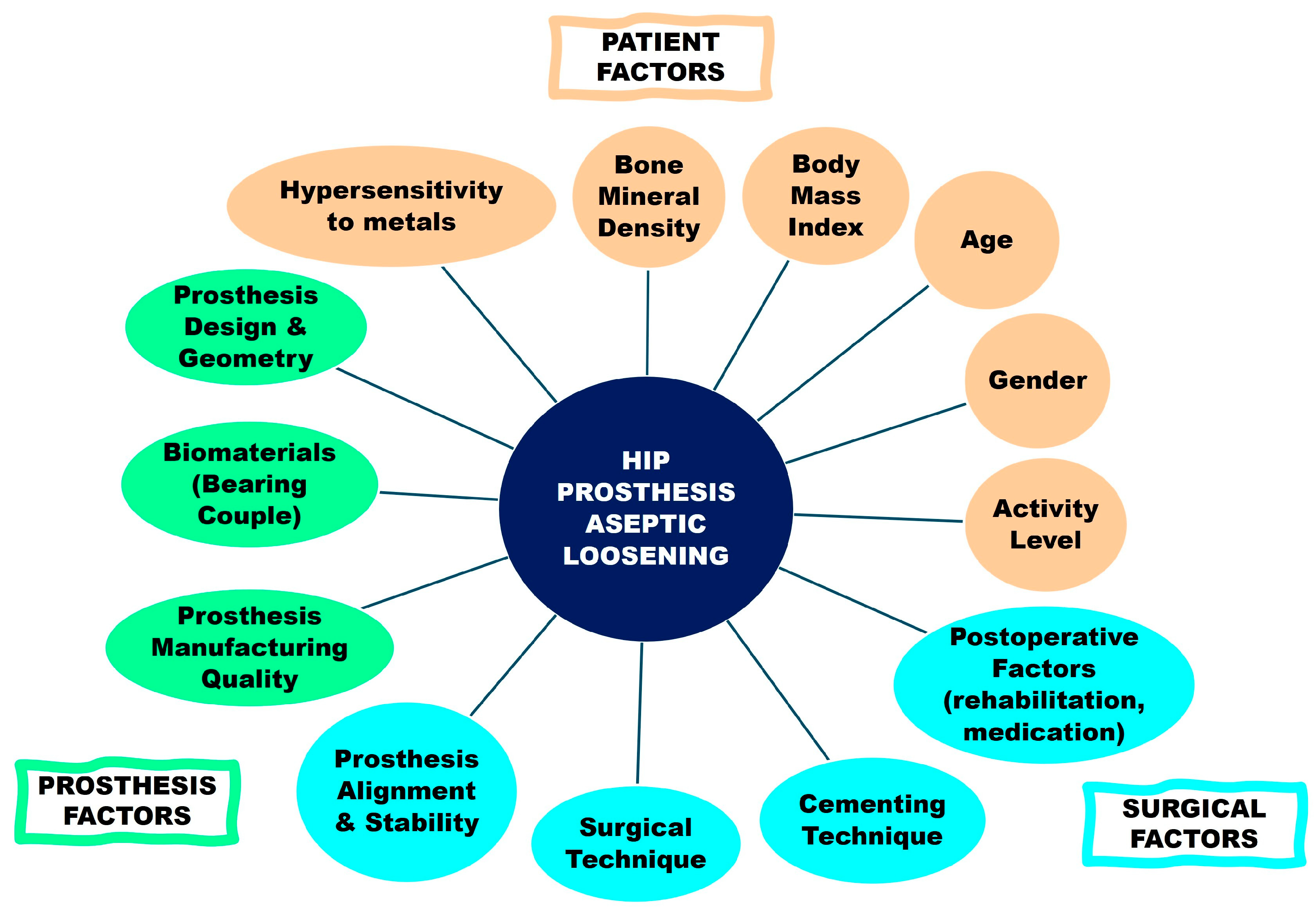
10]. The factors that affect the functionality of hip prosthesis can be classified into three categories: patient-related risk factors, prosthesis-related risk factors, and surgical risk factors [
11]. Among these reactions are metal delayed hypersensitivity and metal allergy, aseptic lymphocyte-dominant vasculitis-associated lesion (ALVAL), pseudotumor, metallosis, and granulomatous reaction [
12]. In addition, failures related to the femoral component include aseptic necrosis of the remaining bone within the femoral head and femoral neck fractures.
Figure 1 reveals the main factors for hip prosthesis loosening for each category.
Patient-related risk factors include mainly those that can be collected before surgical intervention, such as age, gender, body mass index, activity level, hypersensitivity to metals, and bone mineral density. In the case of hip resurfacing arthroplasty with a BHR prosthesis, bone mineral density is a very important factor due to its relevance to femoral component stability. Unfortunately, our research reveals that most of the patients did not undergo these investigations before surgery.
Prosthetic design is another important factor influencing the survival of hip resurfacing implants. Parameters such as the cup articular arc angle (CAAA), which defines the portion of the acetabular cup that articulates with the femoral head, or the radius of the acetabular component rim, can influence component contact and wear [
13].
Related to the implant position, a strong positive correlation between high inclination angles of the acetabular component and revision is mentioned. The resultant edge loading provokes accelerated wear, with particle release.
Regarding the implant size, there is strong evidence to suggest that smaller components are associated with increased metal wear debris owing to poorer fluid lubrication. Also, there have been descriptions of impingement between the acetabular and femoral components, leading to wear and soft-tissue–metal reactions. Reducing the size of the femoral component to conserve acetabular bone will reduce the head–neck ratio, a fact that will restrict the range of movement and will increase the risk of impingement.
These, in turn, are influenced by various factors, such as cementing technique, thickness of the cement layer, cement penetration into the bone, osteoporosis, and wrong positioning of the femoral component, usually in varus, which leads to the occurrence of the phenomenon of femoral neck notching [
8,
10].
These, in turn, are influenced by biological factors or factors associated with implantation. Regarding biological factors, osteoporosis, which involves a decrease in bone strength, is one of the main causes of failure. In a study by Shimmin et al. [
10] analyzing data from the National Endoprosthesis Registry in Australia, they identified differences in the incidence of femoral neck fracture among women who underwent resurfacing prostheses, 1.91%, compared to men, who recorded an incidence of 0.98%. This difference was attributed to the onset of postmenopausal osteoporosis. Another study, Carroters et al. [
14] on 5000 Birmingham hip resurfacing (BHR) prostheses, identified femoral neck fracture as the main cause of BHR failure, 1.1% of a revision rate of 3.6%, but did not identify statistically significant differences between women and men. Another biological factor implicated in the failure of resurfacing prostheses is aseptic lymphocytic vasculitis-associated lesions (ALVAL). Examination of tissues from revised metal–metal implants has shown pronounced perivascular lymphocytic infiltration, suggesting a type IV T-cell–mediated hypersensitivity reaction triggered by metal wear debris [
15]. This phenomenon was described by Wiilart in 2005 [
14,
16] as a lymphocyte-dominant delayed-type hypersensitivity reaction. Pandit et al. [
17] used the term pseudotumor to define metallosis in tissues adjacent to resurfacing prostheses, estimating that 1% of cases will develop pseudotumors within a 5-year period after surgery. A pseudotumor is a soft-tissue mass that may develop around joint prostheses, particularly in metal-on-metal hip implants. It is usually associated with adverse local tissue reactions (ALTR) caused by metal wear particles and metal ions [
18]. At the same time, metallosis is the accumulation of metal wear particles, ions, and corrosion products in the periprosthetic tissues and joint fluid surrounding a metallic implant and is caused by mechanical wear of metallic components. Even in almost all published studies about failed BHR prosthesis, the adjacent tissues were affected by metallic particles; some of them suggest that correct surgical technique in an appropriately selected cohort of patients is associated with a low incidence of adverse soft-tissue reactions. Langton et al. [
16] identified an incidence rate of ALVAL of 3.4% in articular surface resurfacing (ASR) prostheses but did not identify this complication in BHR prostheses.
BHR prostheses are made of a cast Co–Cr–Mo alloy, the exact composition of which is not disclosed by the manufacturer. However, it appears to be a variant of the Vitallium alloy (Co 62.50%, Cr 30.80%, Mo 5.10%, Mn 0.50%, C 0.40%, Si 0.30%, Fe 0.40%). The microstructure of cast Co–Cr alloy shows compact precipitates, present in the metal matrix, with carbide characteristics, M
6C, M
7C
3, and M
23C
6 being the most common. When carbides are present as a continuous film at the grain boundary, there is a risk of reducing ductility, impact strength, and favoring the appearance of cracks. Corrosion tests performed in Hank’s Body Fluid and 3%wt NaCl solution show a susceptibility to corrosion of the Co–Cr alloy [
19]. This corrosion process will lead to the release of ions from the alloy component. These ions accumulate in the tissues adjacent to the prosthesis or can enter the bloodstream, having systemic effects [
20,
21].
Also, the acetabular component of the BHR provides superior femoral head coverage compared to the ASR. For example, in the case of a 52 mm diameter cup, the femoral head coverage will be 1620 for the BHR compared to 1510 for the ASR [
16]. Among the factors related to the implantation procedure that influence the survival rate, the cementation process has a major impact. In particular, the depth of cement penetration into the bone is closely correlated with the performance and long-term survival of hip resurfacing prostheses. Studies show that a cement penetration of 3–5 mm is required for good prosthesis fixation [
1]. At a cement penetration greater than 6 mm, thermal necrosis of the cancellous bone or its stiffening may occur, and increased tension at the interface may increase the stress-shielding effect, increasing the risk of stress fracture of the underlying bone [
9]. Thus, excessive cement penetration is associated with loss of the femoral component.
Cement penetration is influenced by a variety of factors, some of which can be controlled by the orthopedic surgeon, such as cement viscosity, pressurization technique, or the use of pulse lavage, and some that cannot be controlled, such as bone density or prosthesis design. Regarding factors that cannot be controlled by the surgeon, osteoporosis, DEXA T-score below −2.5, will lead to rarefaction of the spongy bone, with an increase in the spaces between the bone trabeculae, thus favoring the penetration of the cement into the bone tissue. Cement penetration is also influenced by the design of the femoral component, with the space between the resurfaced bone and the internal face of the prosthesis playing an important role [
1]. If the low-viscosity cementing indication is followed, a cement layer of 2–3 mm is obtained [
22]. The thickness of the cement layer is also associated with an increase in the temperature inside the bone, which can induce thermal necrosis of the underlying bone by destroying osteocytes [
14]. Thus, the thicker the cement layer, the greater the transfer of thermal energy and the risk of thermal bone necrosis. Gill et al. [
23] recommended the use of a suction cannula placed at the lesser trochanter, abundant pulsatile lavage, and rapid reduction in the joint to lower the temperature at the bone–cement interface. Consequently, both the thickness of the cement mantle and the degree of cement penetration influence the transfer of mechanical forces to the underlying bone and the viability of the bone tissue. An increase in these parameters is associated with a higher risk of stress shielding and reduced mechanical strength of the resurfaced bone [
22].
However, the data reported in the literature can sometimes be controversial. In the study by Beaule et al. [
1], the effect of a thin cement layer was analyzed in the case of Birmingham hip resurfacing (BHR) prostheses, obtained by following the low-viscosity cementing instructions. The authors reported a thickness of the cement layer of approximately 1 mm at the level of zone 3, concomitantly with an increased degree of cement penetration into the bone, of 65.62%, significantly higher compared to other prostheses of similar design, such as ASR, where the penetration was only 12.25%. Consequently, the average depth of cement penetration was statistically significantly higher in the case of BHR prostheses compared to the other types of prostheses analyzed, in all three evaluated zones. Despite this increased cement penetration, BHR prostheses had a relatively low revision rate of 4.3% at 5 years compared with ASR prostheses, which had a revision rate of 12%, according to data from the National Arthroplasty Register in England and Wales [
24]. In addition, Carrothers et al. [
14] reported a revision rate of 3.6% in a large study of approximately 5000 BHR prostheses, supporting the favorable performance of this type of implant in the medium term.
Table 2 and
Table 3 present an overview of the survival and failure rates reported in previous studies on BHR and ASR, including the number of cases, follow-up period, overall failure rate, and the distribution between female and male patients.
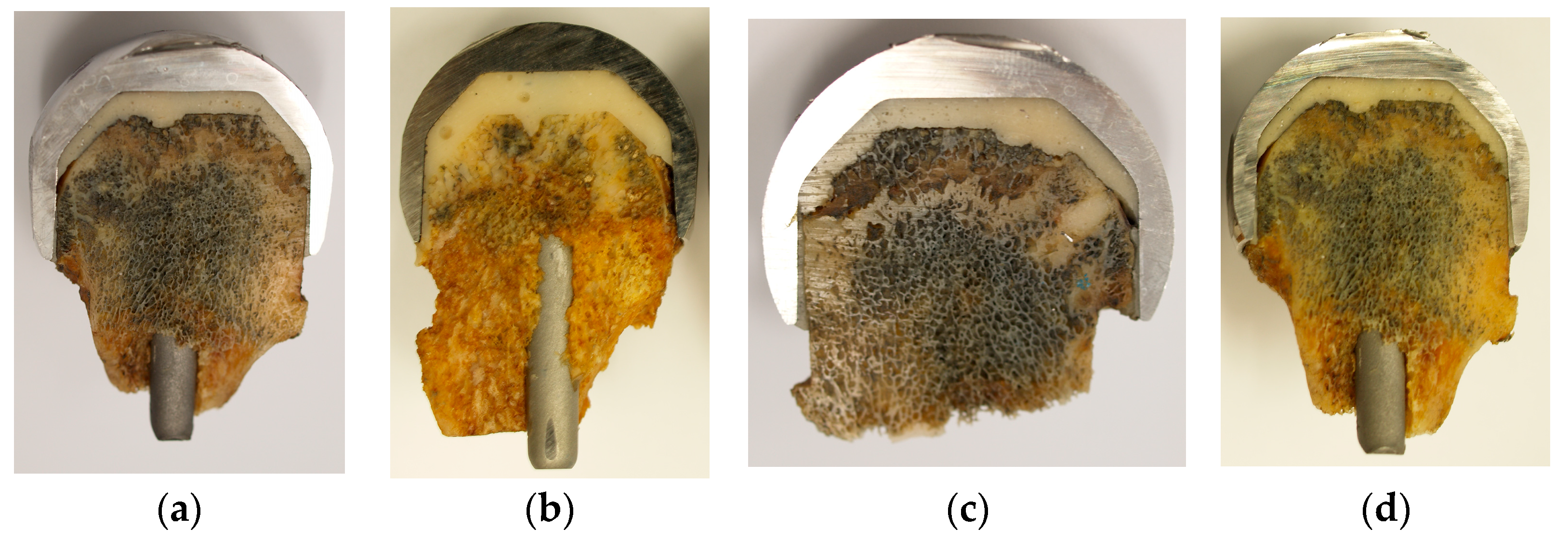
The aim of this research was to investigate the characteristics of the cement layer and the failure mechanisms associated with the bone–cement and cement–prosthesis interfaces in retrieved Birmingham hip resurfacing femoral components. This was achieved through a combined analysis using radiographic evaluation, stereomicroscopy, scanning electron microscopy (SEM), and histopathological examination of explanted prostheses. We hypothesize that early failure of BHR prostheses is strongly associated with nonuniform cement distribution, excessive cement penetration into the bone, and defects at the cement–prosthesis interface, collectively compromising the mechanical stability of the implant.
3. Results
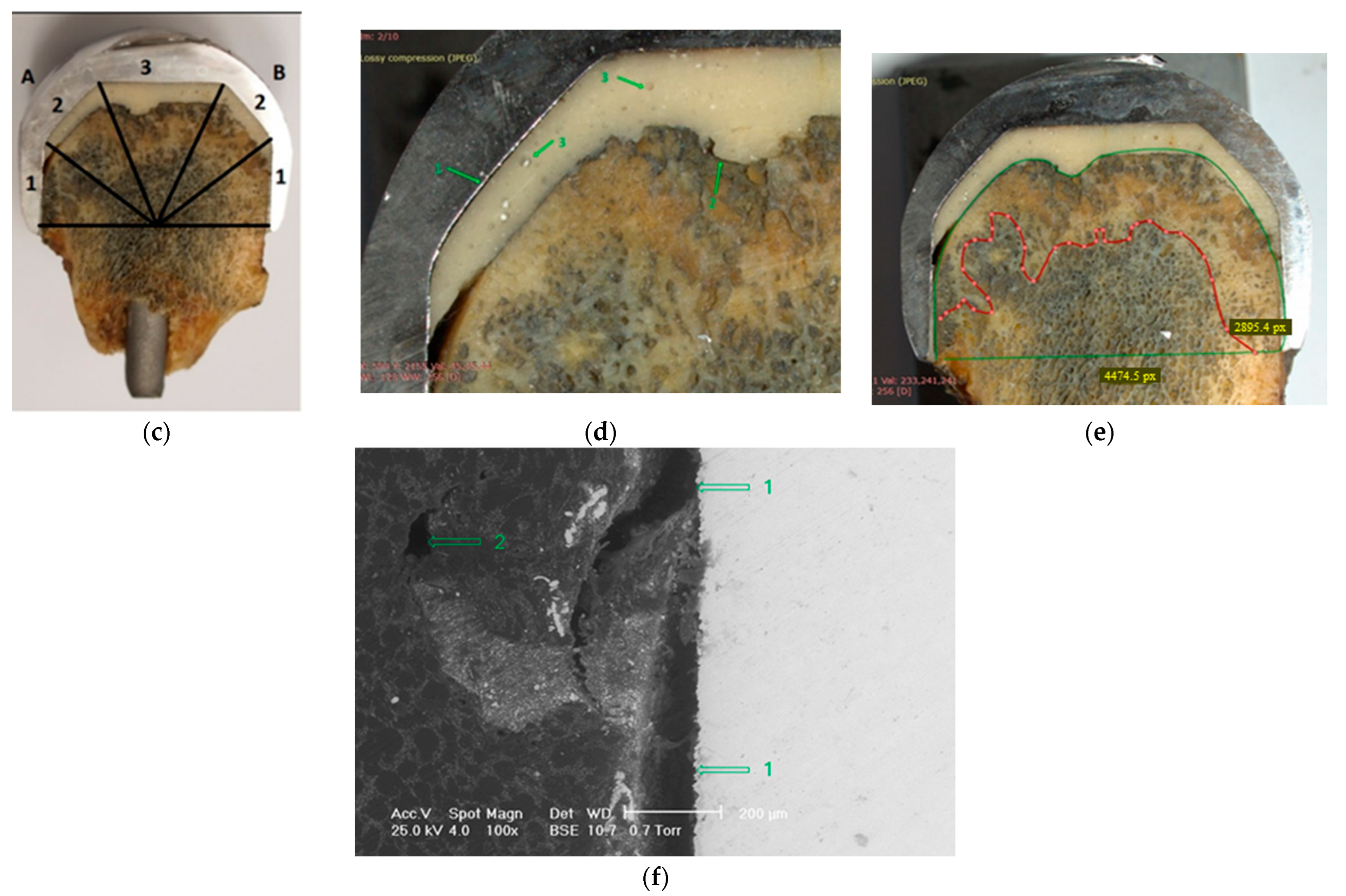
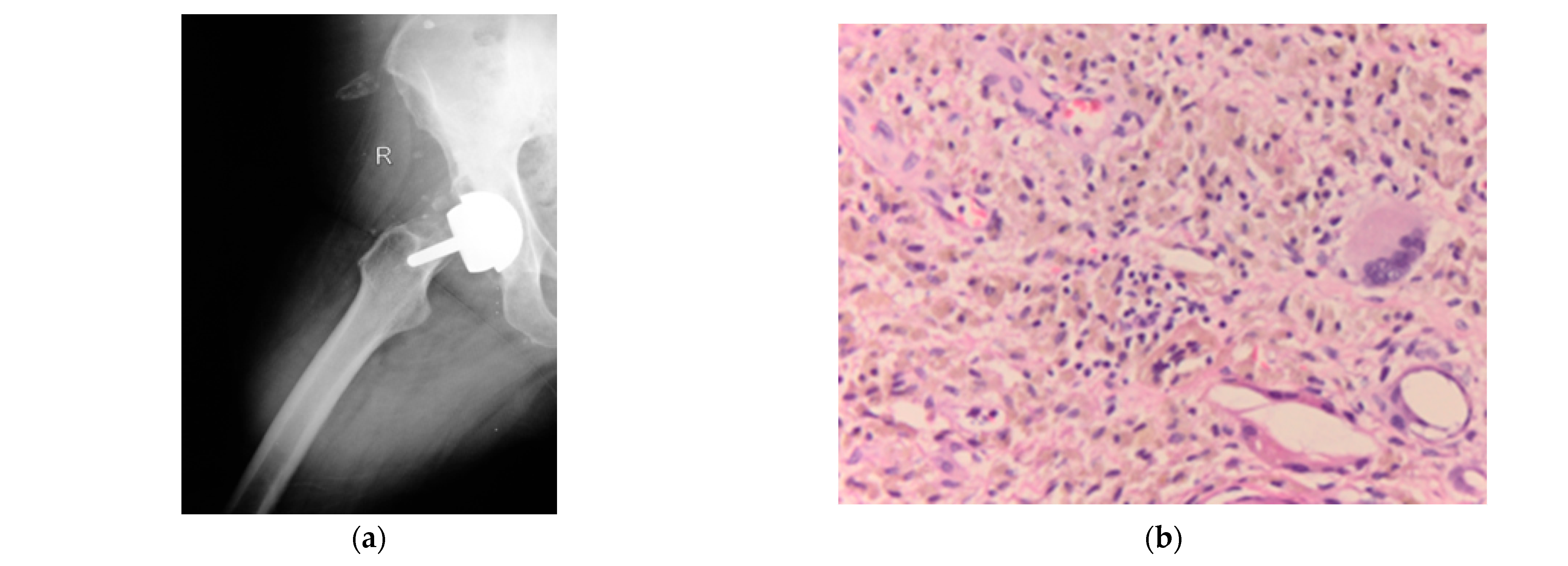
Clinical case 1: According to the pre-established work protocol, the results obtained for the first clinical case are summarized in
Figure 4. A 72-year-old patient presented to the orthopedic department after 43 months since the initial surgery, complaining of local hip pain in the anatomical region where the Birmingham hip resurfacing was implanted. Following the radiograph (
Figure 4a), a fracture of the right (R) femoral neck was observed, and revision of the BHR prosthesis was decided. The external diameter of the femoral component is known to be 48 mm.
Figure 4b illustrates the result of histopathological analysis of tissue harvested from the area of the defect located at the bone–cement interface. Inflammatory tissues were identified at this level, indicating a local inflammatory response. Using hematoxylin-eosin (HE) staining at 400× magnification, a granulomatous inflammatory foreign body reaction was identified, characterized by multinucleated giant cells surrounding pseudo-cystic spaces containing fine granular material (possibly radiopaque material from prosthetic cement) and macrophages with foamy cytoplasm and fine granulations. Moderate ALVAL grade (score 5): macrophage cell infiltration score 3 and inflammatory reaction with multinucleated giant cells, score 2, without synovial lining in the section.
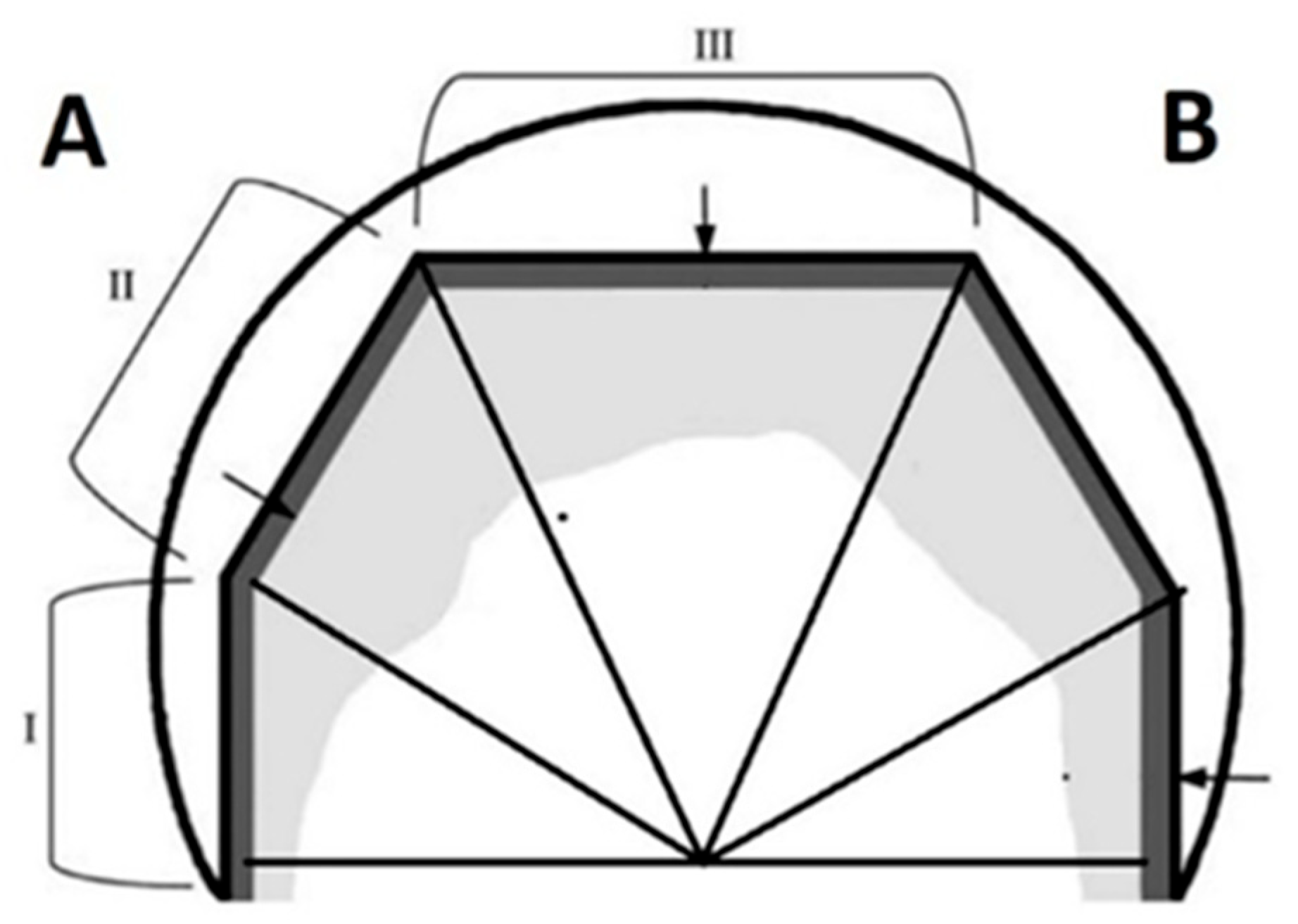
The section obtained for explant 1 was divided into three areas of interest, as can be seen in
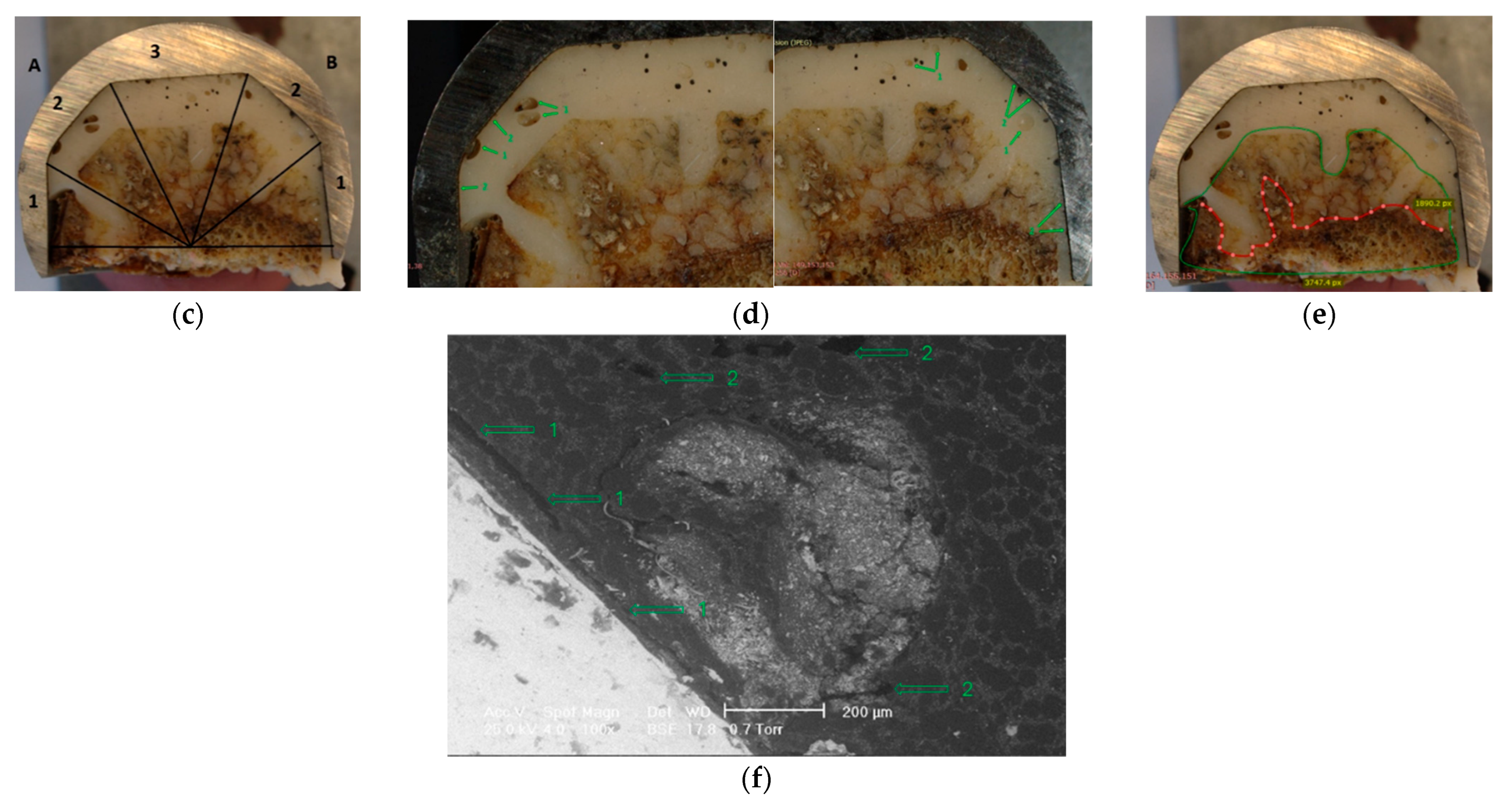
Figure 4c, according to the pre-established work protocol. This sectioning allows for detailed analysis of the thickness of the cement layer, respectively, the depth of cement penetration into the bone. The detailed image presented in
Figure 4d highlights the phenomenon of loosening at the prosthesis–cement interface (arrow 1), and at the bone–cement interface (arrow 2). The phenomenon of loosening significantly reduces the long-term success of BHR-type prostheses. The presence of air bubbles in the structure of the cement layer is also observed (arrow 3). These air bubbles appear during the mixing and application process of the cement, indicating a reduced efficiency of the cementation technique used in this case. The analysis of the average thickness of the cement layer and average cement penetration for explant 1, measured in the three areas of interest, is presented in
Table 8.
Scanning electron microscopy (SEM) analysis confirms the presence of defects previously identified in the detailed images of the cement layer, as illustrated in
Figure 4f. Cracks are evident at the cement–prosthesis interface (arrow 1), associated with loosening, which compromises stability. This is due to insufficient filling of the acetabular cup with cement. Air bubbles are also observed inside the cement layer (arrow 2). SEM analysis provides essential images regarding the homogeneity of the cement, which is crucial for long-term stability.
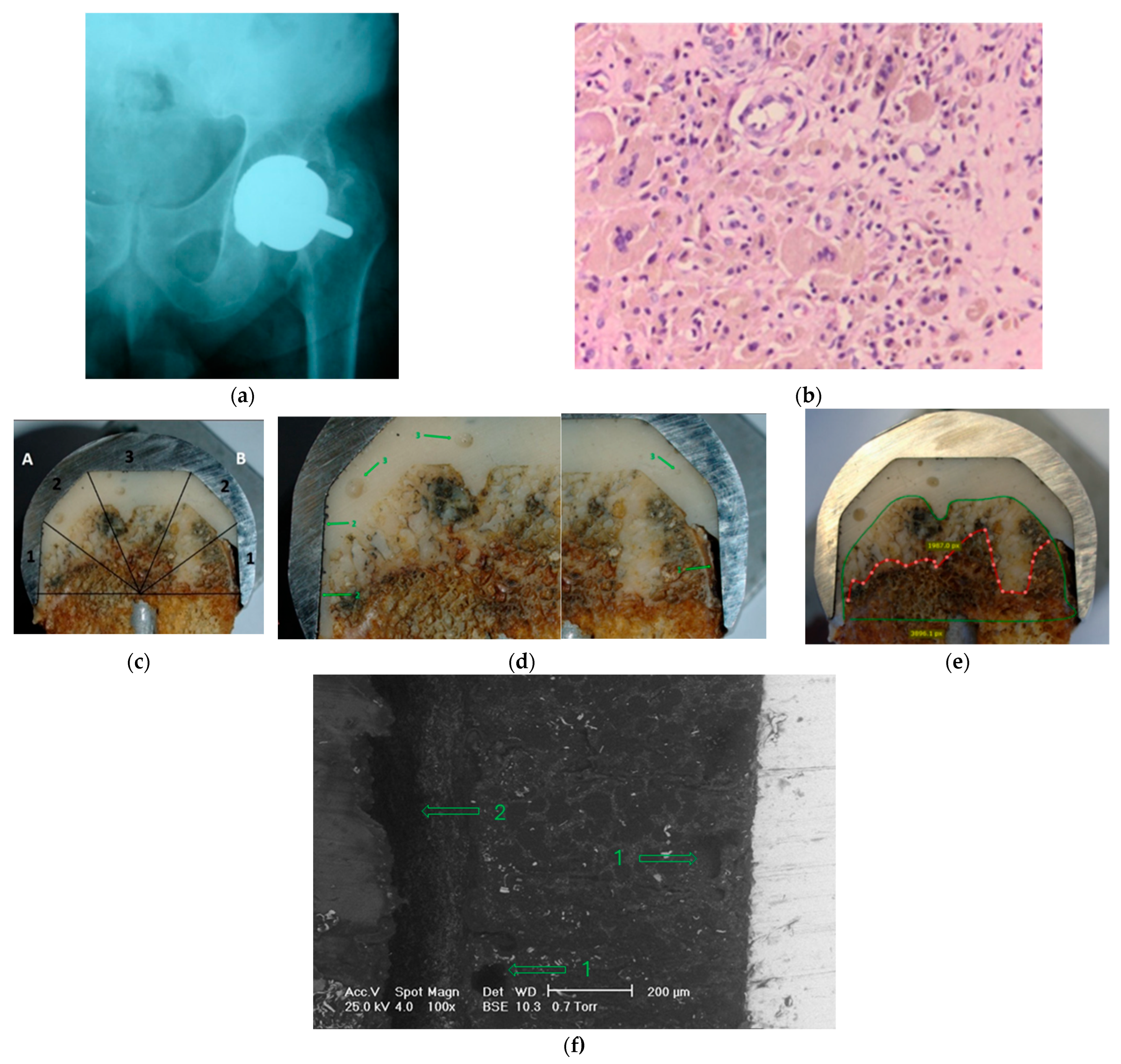
Clinical case 2: According to the pre-established work protocol, the results obtained for the second patient are summarized in
Figure 5. A 69-year-old patient presented to the orthopedic department 48 months after the initial surgery, complaining of local pain in the region where the Birmingham hip resurfacing prosthesis was implanted.
The radiography
Figure 5a shows a fracture of the right femoral neck. It is known that the external diameter of the femoral component is 44 mm.
Figure 5b highlights aspects of the tissue reactions observed in the case of the explant 2.
The microscopic image at 400× magnification using Hematoxylin-Eosin staining reveals fibrous connective tissue with a granulomatous foreign body inflammatory reaction, characterized by the presence of giant multinucleated cells grouped around pseudo cystic spaces, as well as bony splinters embedded in fibrous connective tissue, visible on the left side of the image. Histopathological analysis highlights the complexity and diversity of the inflammatory and vascular responses associated with these prostheses, indicating that the presence of granulomatous inflammatory reactions may significantly contribute to failure. Granulomatous reactions can lead to a moderate ALVAL (score 6): macrophage cell infiltration, score 3, and inflammatory reaction with multinucleated giant cells, score 3, instability due to fibrous tissue formation, which cannot ensure proper structural integration.
The section obtained for explant 2 was divided into three areas of interest, as can be seen in
Figure 5c, according to the pre-established work protocol. The detailed images presented in
Figure 5d highlight the absence of the cement layer in area 1B (arrow 1). Also, the loosening phenomenon at the prosthesis–cement interface is highlighted (arrow 2). Finally, the presence of air bubbles in the cement layer structure is observed in all investigated areas, highlighted by arrow 3. The analysis of the average thickness of the cement layer and average cement penetration for explant 2, measured in the three areas of interest, is presented in the following
Table 9.
Scanning electron microscopy (SEM) analysis confirms the features previously identified in the detailed image at the cement layer, targeting the cement–prosthesis interface (
Figure 5f). Multiple cracks and air bubbles are evident in the cement layer structure (arrow 1), which predisposes it to the loosening phenomenon, compromising stability. Also, the lack of homogeneity of the cement is observed, as well as the presence of air bubbles, which negatively influence the cement–prosthesis interaction, as well as the bone–cement interaction. In addition, local absence of the cement layer is observed (arrow 2).
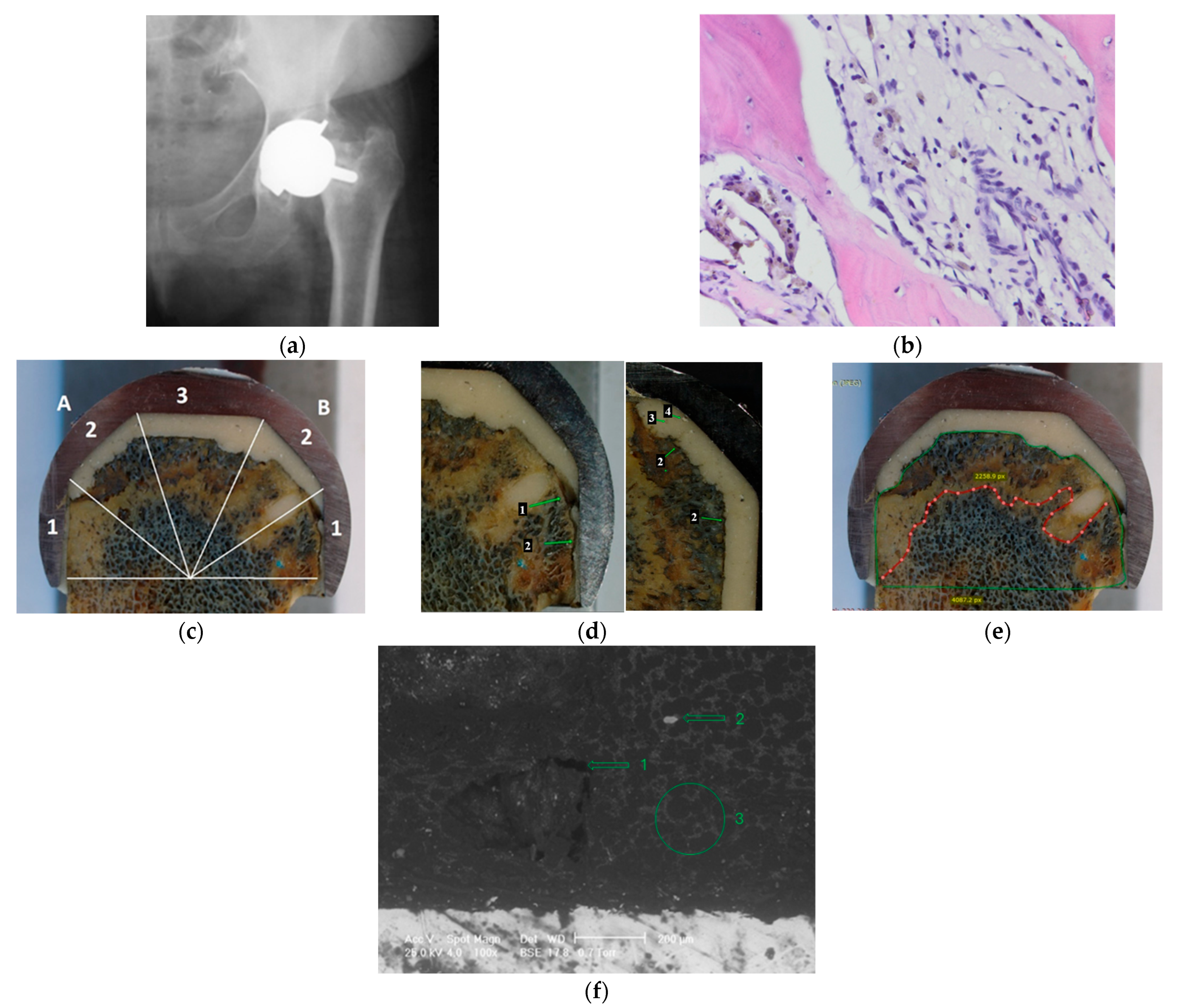
Clinical case 3: According to the pre-established work protocol, the results obtained for the third patient are summarized in
Figure 6. A 71-year-old patient presented to the orthopedic department 46 months after the initial surgery, complaining of local pain in the region where the Birmingham hip resurfacing prosthesis was implanted. The radiological examination, shown in
Figure 6a, revealed the presence of a fracture at the level of the left femoral neck. Also, the external diameter of the femoral component was 44 mm. In
Figure 6b, the microscopic image with Hematoxylin Eosin staining at a magnitude of 400× highlights mature spongy bone tissue with intertrabecular fibrosis and, on the right side of the image, a granulomatous inflammatory reaction of the foreign body granuloma type around small pseudo cystic spaces and many macrophages having cytoplasm with yellowish-brown granular pigment; these images highlight the complexity of the inflammatory and fibrotic processes involved in the failure of BHR prostheses. Moderate ALVAL (score 6): macrophage cell infiltration, score 3, and inflammatory reaction with multinucleated giant cells, score 3. Histological analysis of explant 3 of the BHR reveals multiple aspects contributing to prosthesis failure, highlighted by the structural and cellular details observed.
The section obtained for explant 3 was divided into three areas of interest, as can be seen in
Figure 6c, according to the pre-established working protocol. The detailed macroscopic images presented in
Figure 6d highlight the local absence of the cement layer in area 1B (arrow 1). The presence of air bubbles incorporated into the cement layer structure is observed in all areas investigated, highlighted by arrow 3, plus the presence of cement granules, highlighted by arrow 4. Also, at the bone–cement interface, a stable bond was not observed, with a separation space between the two structures being evident in area 2B, arrow 2. The stability of the bone–cement interface is essential, as this interaction ensures stable anchorage during normal functioning and influences the long-term durability of the prosthesis [
39]. The analysis of the average thickness of the cement layer and average cement penetration for explant 3, measured in the three areas of interest, is presented in
Table 10. The thickness of the cement layer values was different in all the areas analyzed, highlighting a non-uniform distribution of the cement layer.
Scanning electron microscopy (SEM) analysis confirms the presence of defects previously identified in the detailed images of the cement layer, as illustrated in
Figure 6f. Cracks in the cement layer, probably associated with the polymerization process, as well as air bubbles generated during mixing, were highlighted. An inhomogeneous cement structure is also observed.
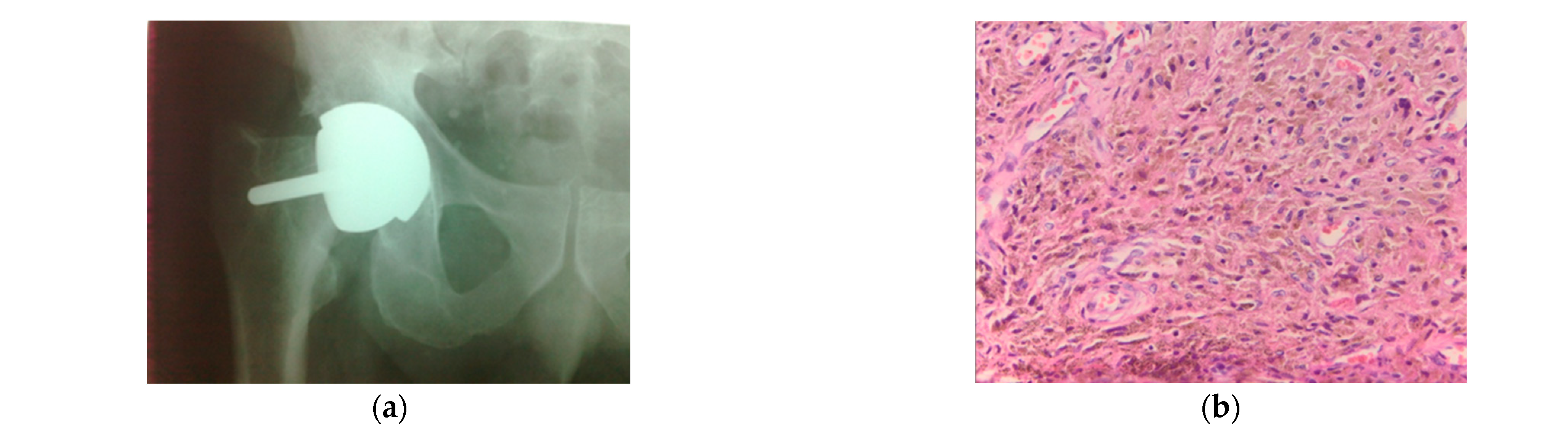
Clinical case 4: According to the pre-established work protocol, the results obtained for the fifth patient are summarized in
Figure 7. A 67-year-old patient presented to the orthopedic department 45 months after the initial surgery, complaining of local pain in the anatomical region where the Birmingham hip resurfacing prosthesis was implanted.
The radiological examination, shown in
Figure 7a, revealed the presence of a fracture at the level of the right femoral neck. Also, the external diameter of the femoral component was 42 mm. In
Figure 7b, the histological analysis revealed the presence of inflammatory-looking membranes in area 1B, corresponding to the region with a major cementation defect.
Microscopic examination, performed by Hematoxylin-Eosin staining, at a magnification of 400×, revealed an inflammatory tissue characterized by a relatively low number of macrophages. Some of these cells showed intracytoplasmic inclusions of fine, granular pigment, blackish in color, suggestive of a metallic pigment.
ALVAL low grade (score 3): macrophage cell infiltration, score 1, and inflammatory reaction with multinucleated giant cells, score 2.
The section obtained for explant 4 was divided into three areas of interest, as can be seen in
Figure 7c, according to the pre-established working protocol. The detailed macroscopic images presented in
Figure 7d highlight the local absence of the cement layer in area 1A. Also, cementation defects, incorporated air bubbles (arrow 1), and loosening phenomenon at the cement–prosthesis interface (arrow 2) are observed.
The analysis of the average thickness of the cement layer and the average cement penetration, measured in the three areas of interest, is presented in
Table 11.
Scanning electron microscopy (SEM) evaluation confirmed the presence of defects previously identified in the macroscopic images. Loosening phenomenon at the cement–prosthesis interface (arrow 1), together with an inhomogeneous cement structure, characterized by cracks and air bubbles (arrow 2).
4. Discussion
The findings from all four retrieved Birmingham hip resurfacing femoral components suggest a possible pattern indicating an association between early failure and deficiencies in cementation. In all cases, the cement mantle was distributed unevenly, with a tendency toward excessive accumulation in the dome region and insufficient coverage in the lateral zones. This non-uniform morphology may alter load transfer and create local biomechanical conditions that favor crack initiation, micromotion, and progressive loosening of the femoral component.
Clinical case 1: The values of the thickness of the cement layer were different in all the areas analyzed, highlighting a non-uniform distribution of the cement layer. In addition, in area 1A, the local absence of the cement layer was observed, indicating direct contact between the bone tissue and the metal prosthesis.
According to data from the literature, the thickness of the cement layer is between 2 and 3 mm [
9,
40,
41]. A cement thickness of over 5 mm is considered excessive and may be associated with an increased risk of osteonecrosis of the femoral head. Also, increasing the thickness of the cement layer tends to increase strain shielding in the proximal femur. The values obtained from the measurement thickness of the cement layer for explant 1, 2.90 mm, 2.75 mm, and 1.85 mm, respectively, were within the range considered optimal of 2–3 mm for obtaining an efficient fixation of the femoral component. The distribution of the cement revealed maximum values in zone 3, where a thickness of 3.75 mm was recorded, while the lowest values were observed laterally, in zones 1 and 2. This regional variation suggests a non-uniform distribution of the cement, with preferential accumulation in the upper region of the femoral head, an aspect frequently reported in the literature and influenced by the geometry of the implant, the cementing technique, and the local conditions of the cancellous bone. Noble et al. [
42] suggested that an optimal cement penetration for proper fixation in cancellous bone is 3 to 5 mm. Increased values of this parameter are observed, especially in region 3, where the penetration depth significantly exceeds the recommended range of 3–5 mm. Increased values of cement penetration into the bone are also observed in areas 2B and 1B. In zone 2A, the penetration of the cement into the bone is optimum, with a value of 3.40 mm. Among the main factors that contribute to the penetration of cement into the bone are cement viscosity, pulse lavage, and femoral bone quality [
37,
43,
44]. According to data from the literature, excessive cement penetration into the bone can predispose it to thermal necrosis, but minimal penetration is still necessary for fixation. Cement penetration determined in case 1 was 63.7%, representing the proportion of bone tissue area with cement interdigitations in the total bone area located under the implant. Similar results were obtained by Beaulé et al. [
1], who obtained cement penetration values of 66.2 ± 15.5% when using the same low-viscosity cement.
Clinical case 2 revealed that, as in case 1, the thickness of the cement layer varied across all analyzed areas, highlighting a non-uniform distribution. In area 1A (2.09 mm), the thickness of the cement layer is optimal, while in area 1B, the local absence of the cement layer was observed, indicating direct contact between the bone tissue and the metal prosthesis. High values of thickness of cement layer were obtained, especially in zone 3, the average being 6.92 mm, well above the recommended optimal range of 2–3 mm, which predisposes to osteonecrosis of the femoral head. Also, the values obtained in zone 2 are higher than the optimal range, with values of 4.99 mm and 4.93 mm recorded. According to the results obtained, increased values of the average cement penetration depth into the bone are observed mainly in zones 3 and 2. The values obtained are 9.88 mm, 7.43 mm, and 6.67 mm, well above the recommended average depth of 3–5 mm [
41]. In zone 1A, the thickness of the cement layer of 2.70 mm was recorded, a value within the range considered optimal, and in zone 1B, the local absence of the cement layer was observed. The cement penetration into the bone tissue was 51%, a value consistent with the average level of penetration.
Clinical case 3: In area 1A, the thickness of the cement layer, 1.25 mm, is thin compared to the optimal range of 2–3 mm, and in this case, a higher stress will be produced on the cement layer, generating high stress concentrations that favor the initiation and propagation of cracks [
45]. In area 1B, the local absence of the cement layer was observed, indicating direct contact between the bone tissue and the prosthesis. In zone 2, the thickness of the cement layer was within the range considered optimal, with average values of 2.75 mm and 2.82 mm, and in zone 3, the thickness of the cement layer was much greater, being 4.05 mm. Regarding the depth of cement penetration in the investigated areas, significantly increased values were recorded compared to the recommended range of 3–5 mm. Thus, in area 3, an average depth of 8.65 mm was determined, in area 2, the values were 7.00 mm (2A) and 9.05 mm (2B), and in area 1A, a value of 6.05 mm was recorded. These high values are associated with an increased risk of thermal necrosis of bone tissue and bone stress shielding. Cement penetration into the bone is 55.27%, falling within the average values reported for BHR.
Clinical case 4: The analysis of the thickness of the cement layer indicated relatively constant values between the investigated areas, but with a general trend of increasing thickness, especially in area 3 (dome), where a mean value of 6.18 mm was recorded. This value significantly exceeds the recommended optimal range of 2–3 mm for effective fixation of the femoral component. Also, increased values of the thickness of the cement layer were observed in area 2, respectively, 4.73 mm in area 2A and 5.12 mm in area 2B. In contrast, area 1A presented a major cementation defect, characterized by the local absence of the cement layer and direct contact between the bone tissue and the prosthesis. At the same time, in area 1B, the thickness of the cement layer was considerably below the optimal range, with a value of only 1.20 mm. This uneven distribution of cement can lead to local biomechanical imbalances, favoring both stress shielding in regions with thick layers and crack initiation and loosening in areas with insufficient layers. Regarding the depth of cement penetration in the investigated areas, significantly increased values were recorded compared to the recommended range of 3–5 mm. The values obtained were 11.10 mm in area 2B, 10.40 mm in area 2A, and 10.25 mm in area 1. These increased values may be associated with an increased risk of bone tissue damage, including thermal necrosis.
Microscopic and SEM evaluation strengthened the interpretation of the macroscopic findings. Air bubbles, cracks, inhomogeneous cement structure, and loss of contact at the cement–prosthesis interface were repeatedly identified, confirming that the integrity of the cement mantle was compromised. These defects are clinically relevant because they disrupt interface continuity and may facilitate progressive debonding under cyclic loading.
Histopathological examination further suggested that failure was not purely mechanical. Three cases showed moderate ALVAL reactions, and one case showed a low-grade ALVAL response, indicating that biological reactions to metallic wear debris may act together with cementation-related mechanical deficiencies. Therefore, the early failure of the analyzed BHR prostheses may be associated with uneven cement distribution, excessive cement penetration, interface defects, and adverse local tissue response. These observations support the need for careful patient selection, accurate implant positioning, and strict control of the cementation technique in order to improve the long-term performance of BHR prostheses.
6. Conclusions
Analysis of BHR femoral explants highlights correlations between the technical parameters of the cementation process and the characteristics of the patients, in concordance with the failure mechanisms reported already in the literature for the BHR hip prosthesis [
45,
46,
47]. Among the complications observed in the analyzed cases, femoral neck fractures were frequently identified and appeared to be associated with increased cement mantle thickness and greater cement penetration into the underlying bone. In most of the cases analyzed, the thickness layer exceeded the recommended values for the cementation technique using low-viscosity cements, reaching average values of up to 6.92 mm. Also, a cement layer with excessive thickness (5–10 mm) has been associated with increased prosthesis micromotion and an unfavorable distribution of radial stresses, which may promote progressive cement creep [
48]. The average depth of cement penetration is high, exceeding 6–10 mm in some areas. SEM images revealed frequent defects in the cement layer, including cracks, air bubbles, and loss of contact at the cement–prosthesis interface, confirming the hypothesis that the cementation technique may represent an important contributing factor in the mechanical instability of the prosthesis.
In addition to the mechanical factors related to cementation parameters, the histo-pathological evaluation highlighted the presence of inflammatory reactions compatible with aseptic lymphocytic vasculitis-associated lesions (ALVAL). According to the semi-quantitative ALVAL scoring system, three of the analyzed cases presented a moderate ALVAL reaction, characterized by macrophage-dominated inflammatory tissue associated with multinucleated giant cells and lymphocytic infiltration, while one case showed a low-grade ALVAL response. The moderate ALVAL reactions were associated with macrophage infiltration scores of 3 and inflammatory giant cell reactions scoring 2–3, indicating a significant biological response to metal wear particles. In one case, the synovial lining was absent in the analyzed section, suggesting advanced tissue alteration. These findings confirm that, besides mechanical instability related to cementation defects, biological reactions induced by metal debris may contribute to the failure process of metal-on-metal resurfacing prostheses.
The presence of moderate ALVAL reactions in most analyzed cases suggests that in-flammatory responses to metal ions and wear particles may act synergistically with mechanical factors such as excessive cement penetration, uneven cement layer distribution, and defects at the cement–prosthesis interface. This interaction may accelerate periprosthetic tissue damage, bone resorption, and ultimately contribute to early femoral component failure. Therefore, both mechanical and biological mechanisms should be considered when evaluating the causes of BHR prosthesis failure.
Failure to comply with these technical parameters may increase the risk of early loosening, frequently associated with femoral neck fracture.
We consider it very important to clearly mention that all clinical adverse effects on the tissues after metal-on-metal hip arthroplasty, such as metallosis, appear in the secondary stage due to other main causes related to the surgery, like prosthesis alignment or cementing technique. These factors could affect the friction between the metallic components of the metal-on-metal prosthesis and induce the presence of metallic wear particles. Especially in the case of BHR prosthesis, due to their short-stem design, bone mineral density, cementation technique, and prosthesis alignment during surgery appear to be the most important factors that could induce early aseptic loosening.
In conclusion, the results support the hypothesis that the failure of BHR hip resurfacing prostheses is influenced primarily by technical errors in cementation and by the patient’s biomechanical peculiarities. Optimization of surgical techniques and rigorous case selection remain essential to increasing the durability of BHR hip prostheses.
However, the present study is observational and descriptive in nature, and the limited number of analyzed cases does not allow the conclusions to be considered definitive. Therefore, the findings should be interpreted with caution and may serve as a starting point for future studies involving larger cohorts, which could provide statistical support and further validation for these observations.




 ,
,