Article

Study on Wall Slip Critical Conditions of High-Burn-Rate Propellants Based on Rheological Tests and Inert Material Cleaning Technology

1
School of Materials Science & Engineering, Beijing Institute of Technology, Beijing 100081, China
2
Hubei Institute of Aerospace Chemical Technology, Xiangyang 441003, China
3
Science and Technology on Aerospace Chemical Power Laboratory, Xiangyang 441003, China
*
Author to whom correspondence should be addressed.
Appl. Sci. 2026, 16(6), 2994; https://doi.org/10.3390/app16062994
Submission received: 11 September 2025 / Revised: 11 February 2026 / Accepted: 26 February 2026 / Published: 20 March 2026

Featured Application

This study provides a technical basis for unmanned and automated cleaning of high-burn-rate propellant mixers by leveraging wall slip behavior of propellants and inert materials, which can replace manual cleaning to eliminate safety risks and improve production automation.

Abstract

Composite solid propellant mixers face severe post-mixing cleaning challenges, especially for high-burn-rate propellants. Manual cleaning remains necessary due to the high viscosity and friction sensitivity of energetic ballistic modifiers (EBMs), which hinders automation and poses safety risks. This study explores the wall slip behavior of high-burn-rate propellants (non-Newtonian fluids)—a phenomenon that departs from the no-slip boundary condition in fluid mechanics (where fluid velocity at the solid surface is assumed to be zero) and occurs when the applied shear stress exceeds a critical value—and its application in mixer cleaning. We performed rheological tests using HAAKE Viscotester IQ (Couette system) (Thermo Fisher Scientific, located in Karlsruhe, Germany) and TA/ARES-G2 rheometer (parallel plate system) (TA Instruments, located in New Castle, DE, USA) to analyze the shear stress, viscosity, and wall slip characteristics of the propellants and inert materials. Tests on three inert materials (A, B, C) showed that A and B exhibit wall slip with shear stress exceeding 2313.6 Pa, achieving complete or near-complete residue removal. In contrast, C does not exhibit wall slip and has insufficient stress, resulting in poor cleaning performance. This work verifies that leveraging the wall slip behavior of high-burn-rate propellants with inert materials can achieve manual-free mixer cleaning, laying a foundation for future unmanned, automated cleaning of high-burn-rate propellant mixers.

1. Introduction

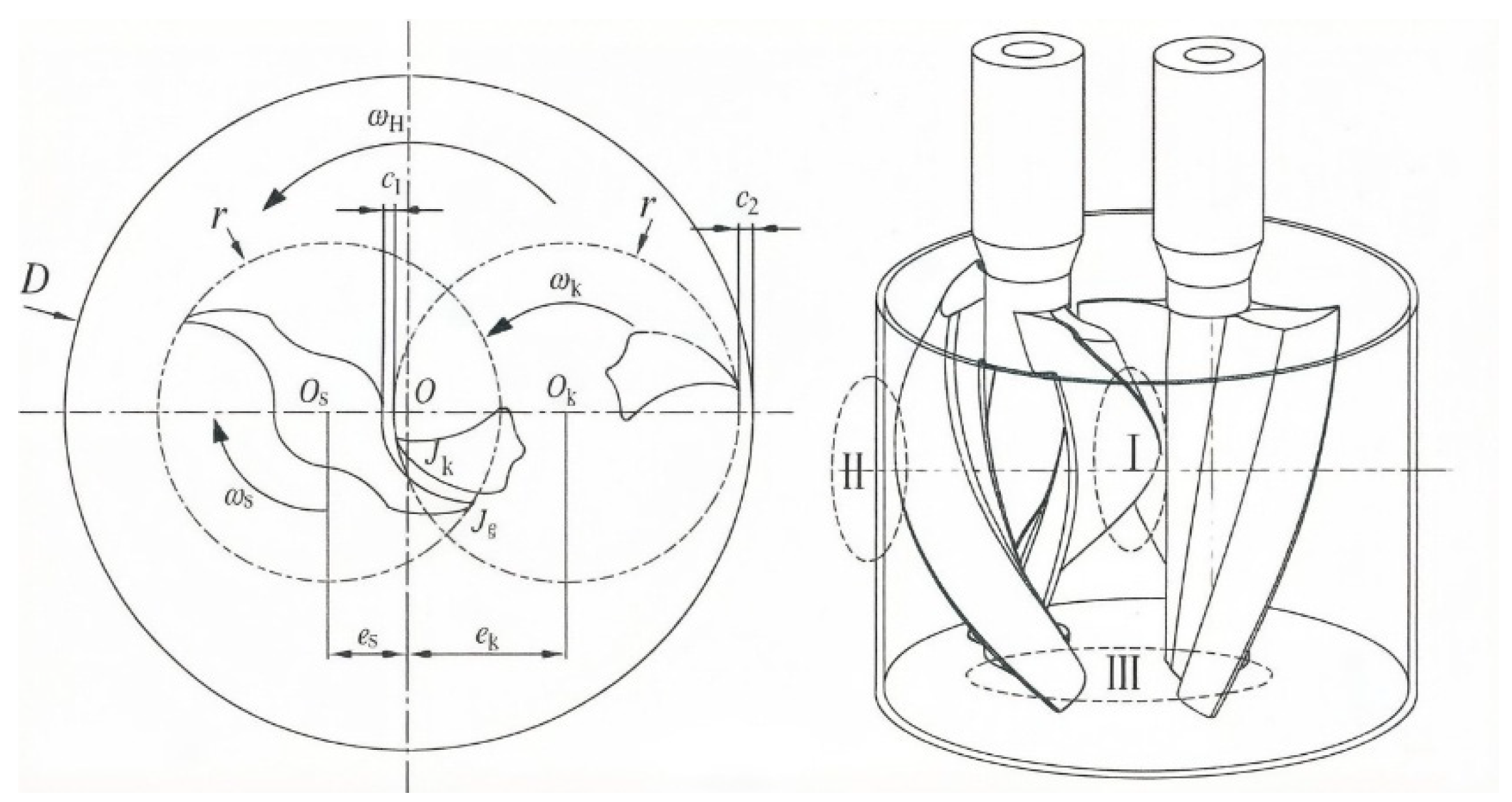
The mixing process is the most critical step in the preparation of composite solid propellants, with the mixer serving as the core equipment for this process. Owing to technological blockades, mature technologies cannot be shared among countries, compelling each nation to conduct independent research and development, thereby forming distinct technical schemes for investigating the mixing process. Against this backdrop, extensive theoretical explorations and experimental studies on laminar chaotic mixing have been carried out in recent years. Koji Takahashi [1] found that the inclined impeller condition leads to more complex flow and higher particle dispersion ability, and other studies reached the same conclusion [2,3,4]. The mixing effect is significantly enhanced by the synergistic effect of the rotating and reciprocating motion of the agitator [5,6]. Mixing power is a function of the eccentricity ratio, and eccentricity of dual impeller systems reduces mixing time [7,8]. A study on mixing power in unbaffled and baffled agitated vessels indicated that baffles do not affect mixing power [9]. Based on the above research results, solid propellant mixers have no baffles and feature a complex paddle structure (Figure 1).
However, post-mixing cleaning remains technically challenging and is largely manual. This not only hinders the advancement of automated designs but also increases safety risks. Specifically, as propellant burn rates increase, the use of finer ammonium perchlorate particles and higher loadings of ferrocene-based catalysts [10,11,12] significantly elevates propellant viscosity. This increased viscosity exacerbates cleaning difficulties, requiring frequent manual scraping. For ultra-high-burn-rate propellants, the use of energetic binders and materials (EBMs)—which exhibit high friction sensitivity and strong initiation capabilities [13,14,15]—further impedes automation efforts and intensifies the risks associated with cleaning operations.
Notably, non-Newtonian fluids exhibit slip at solid surfaces when the applied shear stress exceeds a critical value [16,17,18,19,20,21,22,23,24,25]. This principle can be applied to clean pipes and mixers with a certain degree of viscosity. In the field of oil pipeline cleaning, research is relatively comprehensive, with core approaches primarily falling into two categories: one involves reducing the adhesion force between impurities and the inner pipe wall through chemical methods to create favorable conditions for impurity sliding; the other directly promotes the sliding of impurities on the pipe wall by increasing the shear force acting on them [26,27,28]. Both methods ultimately aim to separate impurities from the pipe wall to achieve cleaning. Methods for studying wall slip can be classified into direct and indirect approaches. Indirect methods include Couette shear flow, parallel plate rheometry, and capillary/slit rheometry; direct methods include optical tracking, laser velocimetry, particle tracking, and other techniques. As a type of non-Newtonian fluid, propellants also undergo wall slip [29,30]. Leveraging this behavior, it is feasible to achieve unmanned and automated cleaning of mixers with adherent propellant residues. However, there are relatively few studies on the wall slip of solid propellants, and few literature reports exist on realizing automatic cleaning of solid propellant mixers by utilizing this wall slip behavior.
To address these challenges, this study first investigates the wall slip mechanism of high-burn-rate propellants via rheological tests, then verifies the feasibility of inert material-based cleaning by comparing it with the critical wall slip stress. The purpose of this paper is to study the wall slip behavior of high-burn-rate propellants and use this behavior to safely clean mixers with adherent high-burn-rate propellants using inert materials.

2. Materials and Methods

2.1. Materials

  • Hydroxy-terminated polybutadiene (HTPB) (binder, Zibo Qilong Chemical Co., Ltd., Zibo, China): Prepared via free radical polymerization, molecular weight = 3800–4600 g/mol, hydroxyl value = 49.4 mg KOH/g.
  • Ammonium perchlorate (AP) (oxidizer, Xiangfan Dongfang Yuxing High Ammonium Salt Co., Ltd., Xiangfan, China): Trimodal particle size distribution with average particle sizes of 300 μm, 100–120 μm, and 1 μm.
  • Aluminum powder (Al, Angang Industrial Fine Aluminum Powder Co., Ltd., Anshan, China): Particle diameter 29 ± 3 μm.
  • Dioctyl adipate (DOA) (plasticizer, Tianyuan Hangcai (Yingkou) Technology Co., Ltd., Yingkou, China).
  • 2,2-Bis(ethyldicyclopentadienyl iron) propane (Catocene) (burn rate-increasing catalyst, Tianyuan Hangcai (Yingkou) Technology Co., Ltd., Yingkou, China).
  • Triphenyl bismuth (TPB) (curing rate-increasing catalyst, Tianyuan Hangcai (Yingkou) Technology Co., Ltd., Yingkou, China).
  • Isophorone diisocyanate (IPDI) (curing agent, Wanhua Chemical Group Co., Ltd., Yantai, China).
  • Polyvinyl chloride (PVC) (filler, Xinjiang Tianye (Group) Co., Ltd., Shihezi, China): Particle size 200 μm.
  • Aluminum oxide (filler, Zibo Honghe Chemical Co., Ltd., Zibo, China): Particle size 5 μm.
  • Energetic ballistic modifiers (EBMs, Hubei Institute of Aerospace Chemical Technology, Xiangyang, China).

2.2. High-Burn-Rate Propellant and Inert Material Preparation

High-burn-rate propellant slurry was prepared in a batch system with a total solid content of 85% (wt%): 18% (wt%) Al powder, 62% (wt%) AP, and 5% (wt%) EBMs. The AP weight ratio (300 μm:100–120 μm:1 μm) was 1:2:2. Liquid components included 8.5% (wt%) HTPB, 3% (wt%) DOA, 3.5% (wt%) Catocene, IPDI, and other functional additives.
Three kinds of inert materials were prepared, consisting of Al powder, PVC powder, DOA, and HTPB:
  • Material A: 48% (wt%) Al powder, 35% (wt%) PVC powder, 5% (wt%) DOA, 12% (wt%) HTPB;
  • Material B: 58% (wt%) Al powder, 25% (wt%) PVC powder, 5% (wt%) DOA, 12% (wt%) HTPB;
  • Material C: 68% (wt%) Al powder, 15% (wt%) PVC powder, 5% (wt%) DOA, 12% (wt%) HTPB.
The formulation design of the three inert materials is based on the differences in surface morphology between Al powder and PVC powder. Adjusting their mass ratio can regulate the shear force exerted by the inert materials on the adherent high-burn-rate propellant during the cleaning process. Specifically, PVC has a poorer surface morphology than Al powder, and a higher PVC content leads to a greater force provided by the inert material during cleaning. The study aims to investigate the effect of solid particle composition on the shear stress and wall slip behavior of inert materials, with the expectation that a lower Al powder ratio (and higher PVC ratio) will result in higher shear stress.
The high-burn-rate propellant and three types of inert materials were prepared using a 5 L vertical mixer (manufactured by the Hubei Institute of Chemical Technology, Xiangyang, China). The mixer consists of a cylindrical barrel and a top cover integrated with two parallel-mounted double helix impellers. Specifically, the central impeller is coaxially installed at the geometric center of the mixer cover and rotates independently about its own axis during mixing. In contrast, the satellite impeller performs a compound motion—rotating around its own axis while revolving around the central impeller at a specified angular velocity. Both impellers have a nominal diameter of 15 cm, with a minimum radial clearance of 4 mm between the satellite impeller and the inner wall of the cylindrical barrel. The distance between the axes of the satellite and central impellers is 7.5 cm, and the ratio of the satellite impeller’s revolution speed to its rotational speed is 1:10. During mixing, the maximum rotational speed of the satellite impeller does not exceed 100 rad/min. Using the shear rate formula γ = ωr/h (where ω is the rotational angular velocity of the satellite impeller, r is the radius of the satellite impeller, and h is the minimum radial clearance between the satellite impeller and the barrel wall), substituting ω = 100 rad/min, r = 7.5 cm (half of the 15 cm nominal diameter), and h = 0.4 cm (4 mm), the maximum shear rate γ = (100 rad/min × 7.5 cm)/0.4 cm ≈ 198 s−1.

2.3. Analytical Methods

2.3.1. Burn Rate Test

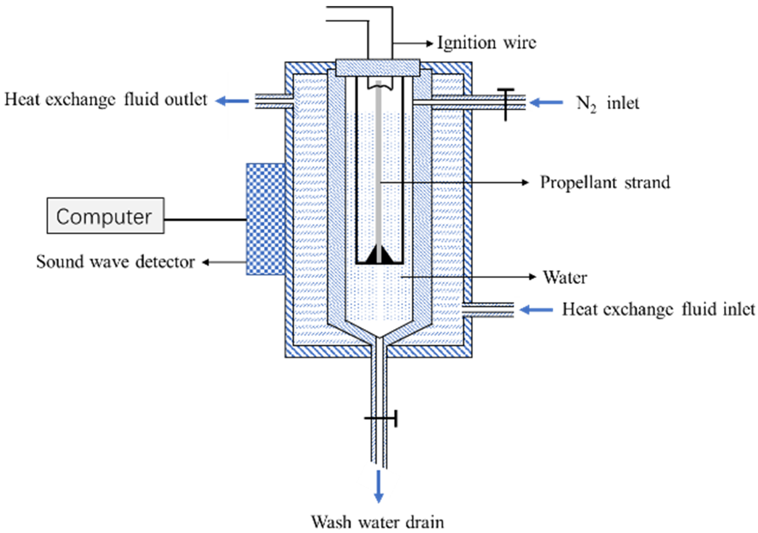
The burn rate was tested using the Crawford bomb method (Figure 2) [31]. Test parameters: propellant strand length = 84.8 mm, cross-sectional dimension = 3 mm × 3 mm, test temperature = 20 °C. The combustion time was determined by digital signal processing of ultrasonic waves generated during combustion. The burn rate was calculated from the strand length and combustion time.

2.3.2. Sensitivity Test

  • Impact sensitivity: Tested using a 5 kg drop hammer to determine the impact energy resulting in a 50% excitation probability.
  • Friction sensitivity: Tested with a WM-1 friction tester (swing angle = 66°, pressure = 2.4 MPa) to obtain the explosion percentage.
  • Electrostatic sensitivity: Tested using an electrostatic spark tester to determine the electrostatic discharge (ESD) energy resulting in a 50% excitation probability.

2.3.3. Rheological Test

Rheological properties of the propellant and inert materials were measured using two systems:
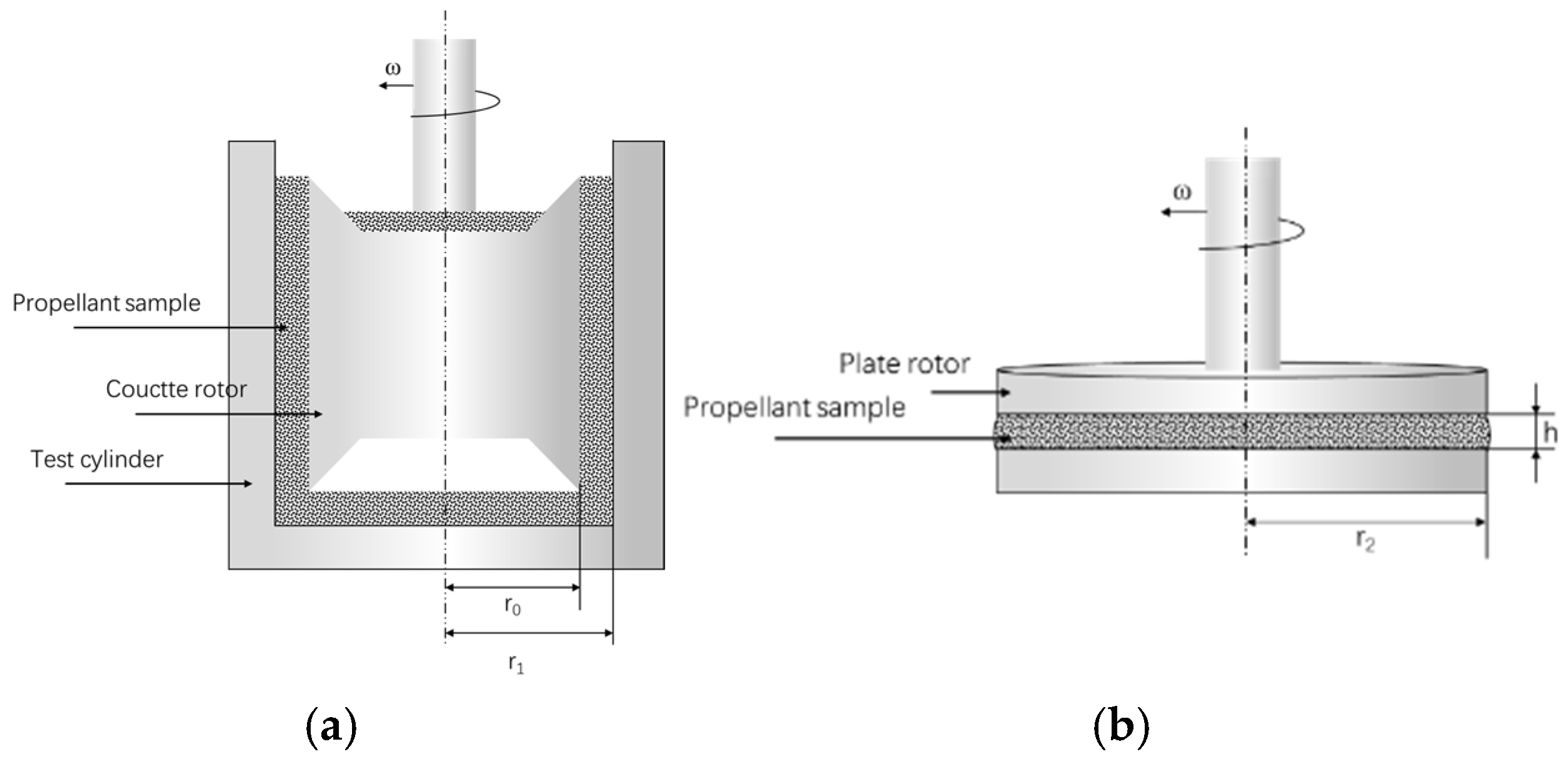
HAAKE Viscotester IQ: Couette system (rotor radius r0 = 12 mm, cylinder radius r1 = 13 mm;
TA/ARES-G2 rheometer: Parallel plate system (rotor radius r2 = 12.5 mm, shear thickness h = 1.5 mm).
Test Conditions: Both instruments use Peltier temperature control with fast temperature response. The test temperature was set to 50 °C. After sample loading, the sample was equilibrated at the set test temperature for 5 min before initiating the test sequence.
Sample Loading Procedure: Uniformly apply the sample to the test interface, remove air bubbles by gentle pressing, trim off the excess sample to ensure the test interface is fully covered without overflow, and adjust the sample thickness to the specified value (1 mm for the Couette system, 1.5 mm for the parallel plate system) to ensure consistent initial conditions.
Rationale for Selecting the Parallel Plate System: Although the parallel plate system has a non-uniform shear field, it offers key advantages: easy sample loading and gap adjustment, and suitability for testing samples containing particles. Given the high solid particle content of the propellant (85 wt%), the parallel plate system is more compatible than other geometries (e.g., cone-plate).
  • Shear direction: Consistent with rotor rotation (Couette) vs. perpendicular to rotor rotation (parallel plate) (Figure 3).
    Figure 3. Schematic diagrams of testing systems: (a) Couette system; (b) parallel plate system.
    Figure 3. Schematic diagrams of testing systems: (a) Couette system; (b) parallel plate system.
    Applsci 16 02994 g003
  • Shear rate change over time: Linear (Couette) vs. exponential (parallel plate).
    γ ˙ c = 0.0556 t 0.1805
    γ ˙ p = 0.0063 e 0.0131 t
  • Shear rate expressions:
    η = τ γ
    γ ˙ p = ω r 0 h
    γ ˙ c = 2 ω r 1 2 r 1 2 r 0 2
where τ = shear stress, ω = rotational angular velocity, η = viscosity, r0 = Couette rotor radius (12 mm), r1 = Couette cylinder radius (13 mm), r2 = parallel plate rotor radius (12.5 mm), h = parallel plate shear thickness (1.5 mm).
  • Key definitions for system comparison:
For homogeneous fluids, shear stress increases continuously with increasing shear rate, and the effect of material stretching during shearing is negligible. In contrast, as typical heterogeneous composites, propellants undergo significant tensile deformation under sustained shear. When the tensile deformation reaches a critical threshold, relative slip occurs between the polymer matrix and dispersed solid filler particles, ultimately resulting in the loss of material continuity. Meanwhile, inherent differences exist in the shear-tensile coupling mechanisms of parallel plate and cylindrical test systems, which directly lead to distinct shear loading modes imposed on the material. Consequently, when the material reaches the critical state characterized by “shear stress decreasing with increasing shear rate”, the extent of material continuity damage induced by tensile deformation differs significantly between the two test systems.
Based on the above analysis, refining relevant concepts is imperative when investigating the wall slip behavior of materials across different shear systems, as detailed below:
  • ηmax: Defined as the point corresponding to the highest viscosity in the rheological curve.
  • Wall slip point: Referring to the point at which the shear stress starts to decrease during the shearing process (shear efficiency β—the ratio of the extension ratios of two systems at the same test moment, used to unify shear characteristics across different test systems).
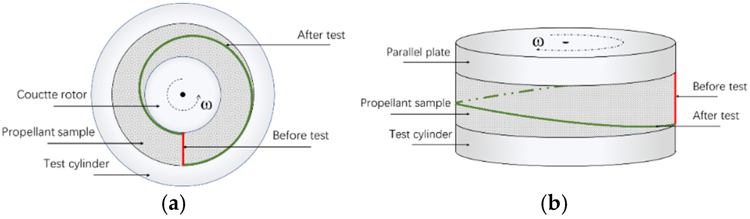
  • Extension ratio (α): Defined as the ratio of the initial length of a material to its length at a specific moment during the test. As illustrated in Figure 4, α is equivalent to the ratio of the length of the green line segment to that of the red line segment.
  • Shear efficiency (β): Defined as the ratio of the extension ratio (α) values, which are measured for two distinct systems at the same moment during the test.
Different test systems (e.g., parallel plate and cylindrical systems) inherently differ in the way they apply shear to materials, and this difference directly leads to deviations in the measured rheological properties of materials under different systems. However, it should be clarified that for the same material, the relative differences in the extension ratio α under different tensile states exhibit significant consistency. This characteristic is an intrinsic property of the material and is not affected by the type of test equipment. Based on this core characteristic, when conducting cross-equipment tests on the same material, the ratio of α values measured by different equipment when the material is in the same tensile state can effectively characterize the differences in tensile properties between equipment, and this ratio is precisely defined as the shear efficiency β between equipment. Essentially, the physical significance of shear efficiency β lies in quantifying the influence of differences in the shear mechanism of different test equipment on the test results of the material’s extension ratio α-β is determined by the inherent properties of the equipment itself, such as the shear loading mode and the shear-tensile coupling mechanism. Meanwhile, the consistency of the relative differences in α under different tensile states of the material ensures the reliability of β as a cross-equipment parameter conversion index, thereby providing theoretical support for the equivalent conversion of key rheological parameters such as critical wall slip between different test systems.

2.4. Application

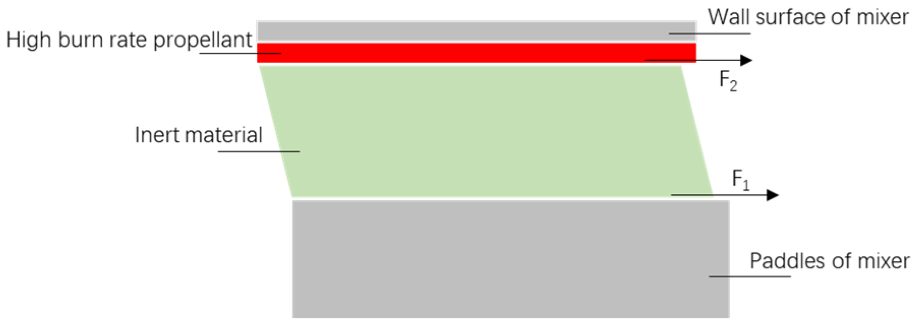
The cleaning process using inert materials mimics manual cleaning: inert materials are added to the mixer with adherent propellant, the mixer is operated, and the mixture of inert materials and propellant residues is removed. The paddles transfer shear stress to the residual propellant via the inert materials to induce wall slip (Figure 5).
The cleaning process using inert materials mimics manual cleaning: inert materials are added to the mixer with adherent propellant (mass ratio of inert material to residual propellant = 5:1), the mixer is operated, and the mixture of inert materials and propellant residues is removed. The paddles transfer shear stress to the residual propellant via the inert materials to induce wall slip (Figure 5).

3. Results and Discussion

3.1. The Basic Properties of High-Burn-Rate Propellant

The burn rate of the test propellant was 62.7 mm/s at 6.86 MPa, as measured using the Crawford bomb method [28].
Sensitivity test results are summarized in Table 1. The propellant exhibited high friction sensitivity (100% explosion rate) and moderate impact/electrostatic sensitivity.

3.2. Rheological Characteristics

Composite solid propellants are materials with high powder particle loading. Under low shear conditions (weak external shear input), the continuous phase (binder system) and dispersed phase (particles including ammonium perchlorate and aluminum powder) form a homogeneous integrated system, exhibiting certain Newtonian fluid behaviors. In contrast, under high shear conditions (strong external shear input), relative motion arises between the continuous and dispersed phases, accompanied by microstructural evolution of the system. Consequently, the material demonstrates distinct non-Newtonian fluid characteristics.
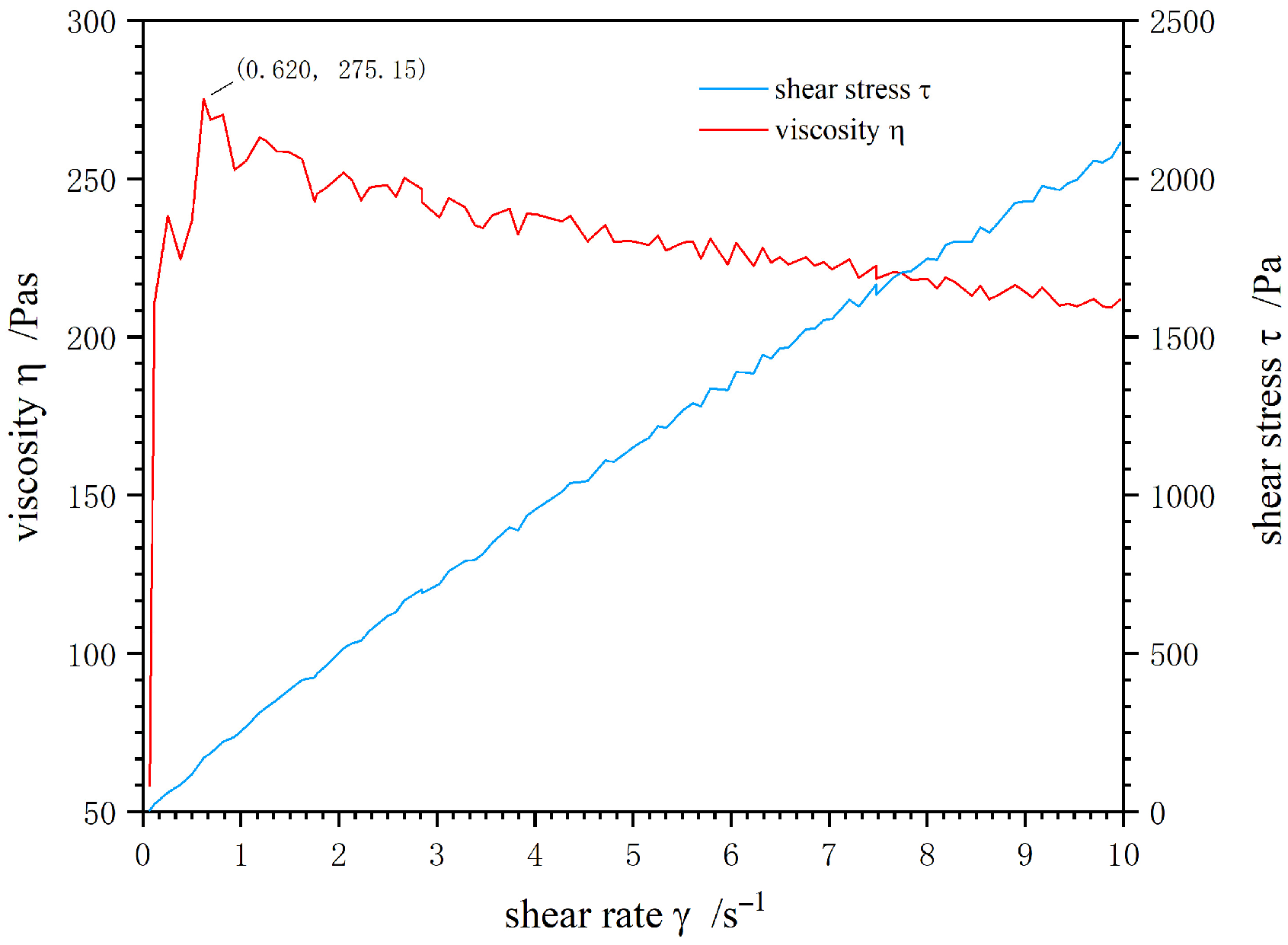
The shear stress and viscosity of the high-burn-rate propellant were tested in the low shear rate range of 1–10 s−1 using the Couette test system (Figure 6). As shown in Equation (1), the shear rate increased linearly with time in the Couette testing system. Figure 6 shows that under low shear rates (1–10 s−1), the high-burn-rate propellant exhibited Newtonian fluid characteristics (stable viscosity, linear shear stress-shear rate relationship), but it is essentially a non-Newtonian fluid. No obvious wall slip behavior of the high-burn-rate propellant was observed in the test, mainly due to the low shear efficiency and low shear rate of the HAAKE viscometer with the Couette test system.
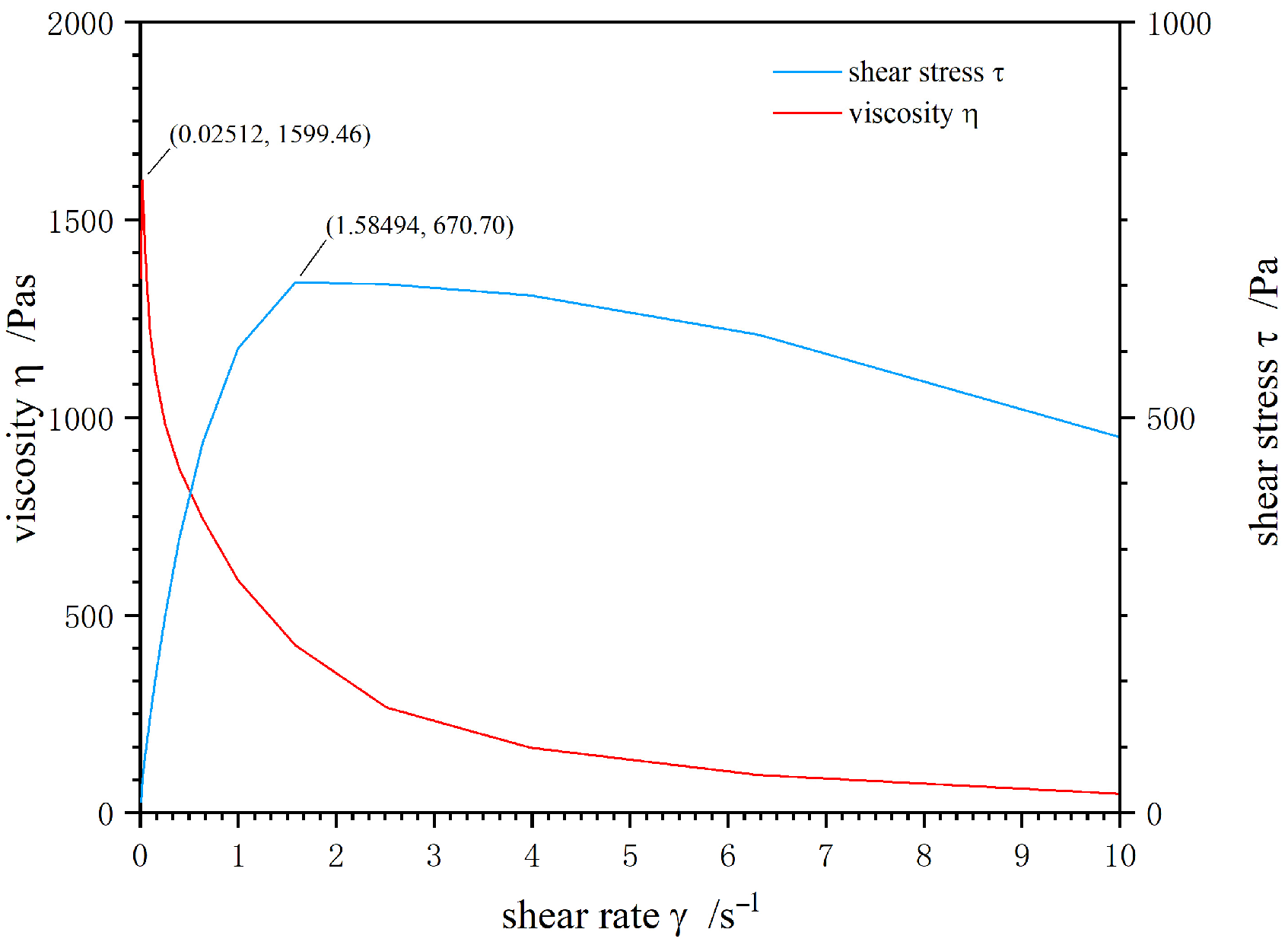
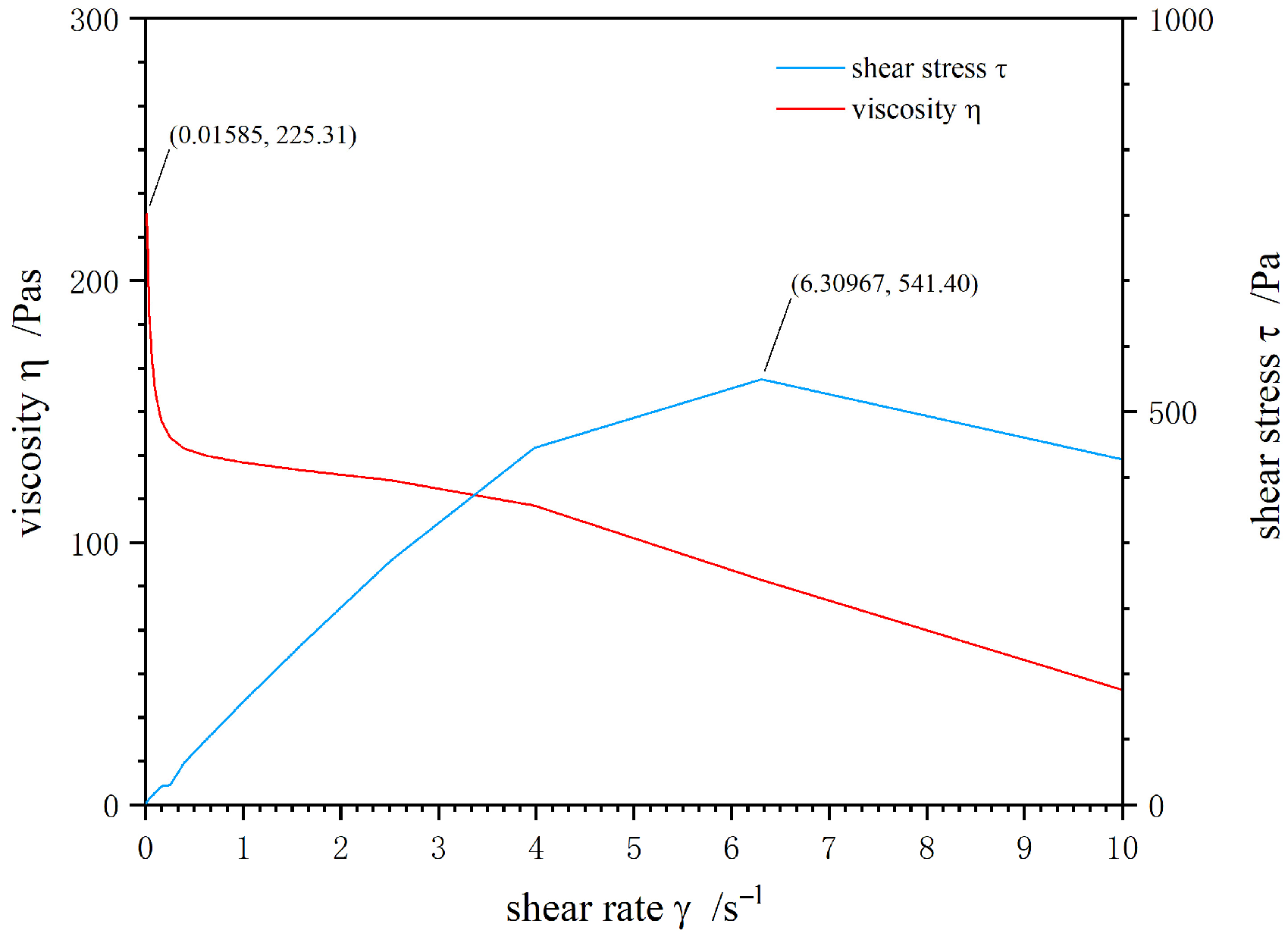
The shear rate is a power function of time based on the natural constant, as shown in Equation (2). The shear stress and viscosity of high-burn-rate propellant were tested by the plate rotor with strong shear effect and a wider shear rate range. When the shear rate is greater than 6 s−1, the significant wall slip behavior of high-burn-rate propellant was observed by using TA viscometer testing with parallel plate (Figure 7).
Significant differences were observed between the two measurement systems. Specifically, wall slip behavior was not detected in the Couette system but was prominent in the parallel plate system. During the viscometer testing process, the high-burn-rate propellant did not exhibit wall slip behavior in the Couette system but did so in the parallel plate system. Moreover, the process of using inert materials to replace manual cleaning of the mixer is similar to the viscosity testing process using the Couette system. Therefore, establishing the relationship between the parallel plate and Couette test systems is the key to studying the wall slip of high-burn-rate propellants.

3.3. The Condition of Wall Slip of High-Burn-Rate Propellant

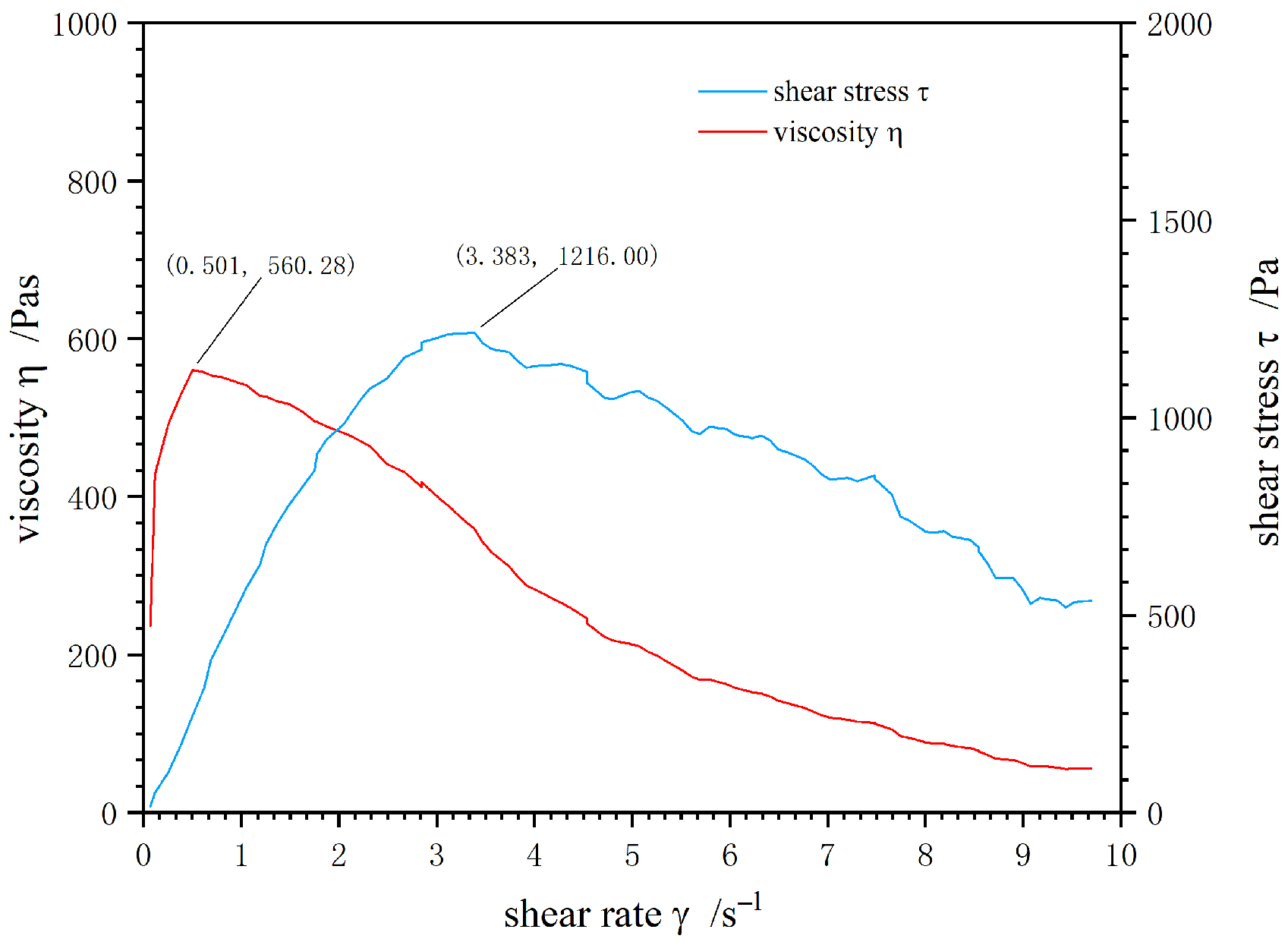
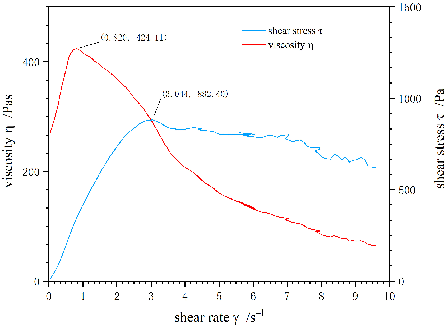
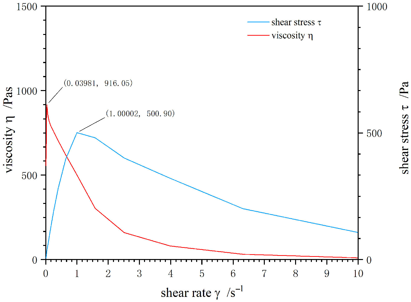
Based on the rheological characteristics obtained from two test systems (Section 3.2), this section further derives the critical conditions for wall slip of high-burn-rate propellants. To determine the shear efficiency β, sample propellant-1 slurry (burn rate: 20 mm/s, solid content: 87 wt%, main components: HTPB/AP/Al = 10/69/18) and sample propellant-2 slurry (burn rate: 12 mm/s, solid content: 87.5 wt%, main components: HTPB/AP/Al = 10/69/18.5) were selected, as they exhibit wall slip in both testing systems (Figure 8, Figure 9, Figure 10 and Figure 11), enabling cross-system comparison.

3.3.1. Physical Logic for Cross-System Comparison

Different test systems apply shear to materials in different ways, leading to differences in measured rheological properties. However, the tensile deformation state of the same material (characterized by the extension ratio α) is an intrinsic property, which is only related to the material’s own microstructure (e.g., particle dispersion, matrix elasticity) and not affected by the test system. Therefore, α can be used as a unified indicator to correlate the two systems, and the shear efficiency β (ratio of α values of the two systems at the same moment) can be used to convert the critical wall slip parameters between the two systems.

3.3.2. Step-by-Step Mathematical Derivation

Step 1: Determine key points (ηmax and wall slip point) in both systems
  • For the sample-1 propellant, ηmax occurs at a shear rate of 0.4225 s−1 (Couette system) and 0.02512 s−1 (parallel plate system); the wall slip point occurs at a shear rate of 3.522 s−1 (Couette system) and 1.5849 s−1 (parallel plate system).
  • For the sample-2 propellant, ηmax occurs at a shear rate of 0.8203 s−1 (Couette system) and 0.03981 s−1 (parallel plate system); the wall slip point occurs at a shear rate of 3.0443 s−1 (Couette system) and 1.0000 s−1 (parallel plate system).
Step 2: Calculate the time corresponding to key points using Equations (1) and (2)
  • For the sample-1 propellant
  • ηmax: t = 12 s (Couette), t = 105 s (parallel plate);
  • Wall slip point: t = 64 s (Couette), t = 420.5 s (parallel plate).
  • For the sample-2 propellant
  • ηmax: t = 18 s (Couette), t = 140.1 s (parallel plate);
  • Wall slip point: t = 48 s (Couette), t = 385.44 s (parallel plate).
Step 3: Calculate rotational angular velocity (ω) of the two systems
  • Couette system:
    ω c = r 1 2 r 0 2 / 2 r 1 2 × 0.0556 t 0.1805
  • Parallel plate system:
    ω p = h / r 2 × 0.0063 e 0.0131 t
Step 4: Calculate rotational angle (θ) via integration of ω over time
  • Couette system:
    θ c = ω c d t
  • Parallel plate system:
    θ p = ω p d t
  • Results: sample propellant-1: ηmax θ c = 0.134 rad (Couette), θ p = 0.171 rad (parallel plate); wall slip point θ c = 7.735 rad (Couette), θ p = 14.194 rad (parallel plate). sample propellant-2: ηmax θ c = 0.899 rad (Couette), θ p = 0.6184 rad (parallel plate); wall slip point θ c = 8.940 rad (Couette), θ p = 12.669 rad (parallel plate)
Step 5: Calculate extension ratio (α) of the two systems
  • Couette system: The initial length L 0 = r 1 r 0 = 1 mm; the stretched length L after testing is
    L = r 0 r 1 1 + θ r 1 r 0 r 0 r 1 2 · r 1 r 2 + 1 r 1 2 d r
    thus, α c = L / L 0 .
  • Parallel plate system: The initial length L 0 = h = 1.5 mm; the stretched length L after testing is
    L = θ p × r 2 2 + h 2
    thus, α p = L / L 0 .
Step 6: Calculate shear efficiency (β)
Shear efficiency β is defined as the ratio of α values of the two systems at the same moment, i.e., β = α c / α p .
The calculation results of the sample propellant tested by the Couette test system and parallel plate test system are shown in Table 2 and Table 3.
Step 7: Derive critical wall slip stress of high-burn-rate propellant
  • For the high-burn-rate propellant, the ηmax point corresponds to γ ˙ = 0.62 s−1 (Couette) and γ ˙ = 0.01585 s−1 (parallel plate); the wall slip point in the parallel plate system corresponds to γ ˙ = 6.3097 s−1.
  • Using the above method, calculate β m (shear efficiency at ηmax point) = 2.29, and α p , s (extension ratio at wall slip point of parallel plate system) = 471.33.
  • Assume β remains constant for the same material, then α c , s (extension ratio at wall slip point of Couette system) = β m × α p , s = 1079.6 .
  • Calculate the stretched length L = α c , s × L 0 = 1079.6 mm ( L 0 = 1 mm for Couette system), and then calculate θ c , s = 89 rad, t = 211.3 s, and γ ˙ c , s = 11.57 s−1 via Equations (8), (10) and (11).
  • Before wall slip, the viscosity η of the high-burn-rate propellant is approximately 200 Pa·s (from Figure 6), so the critical wall slip stress τ = η × γ ˙ c , s = 200 × 11.57 = 2313.6 Pa.
This result indicates that wall slip in the high-burn-rate propellant will occur if the inert material applies a shear stress exceeding 2313.6 Pa.

3.4. Inert Material Cleaning Performance

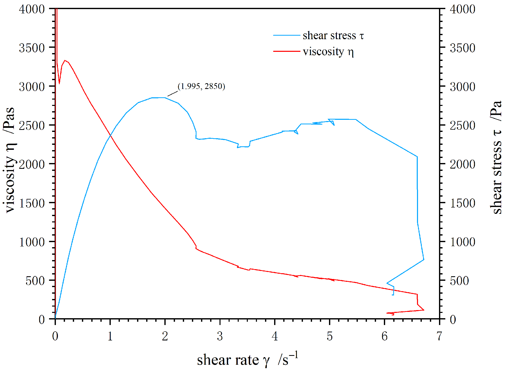
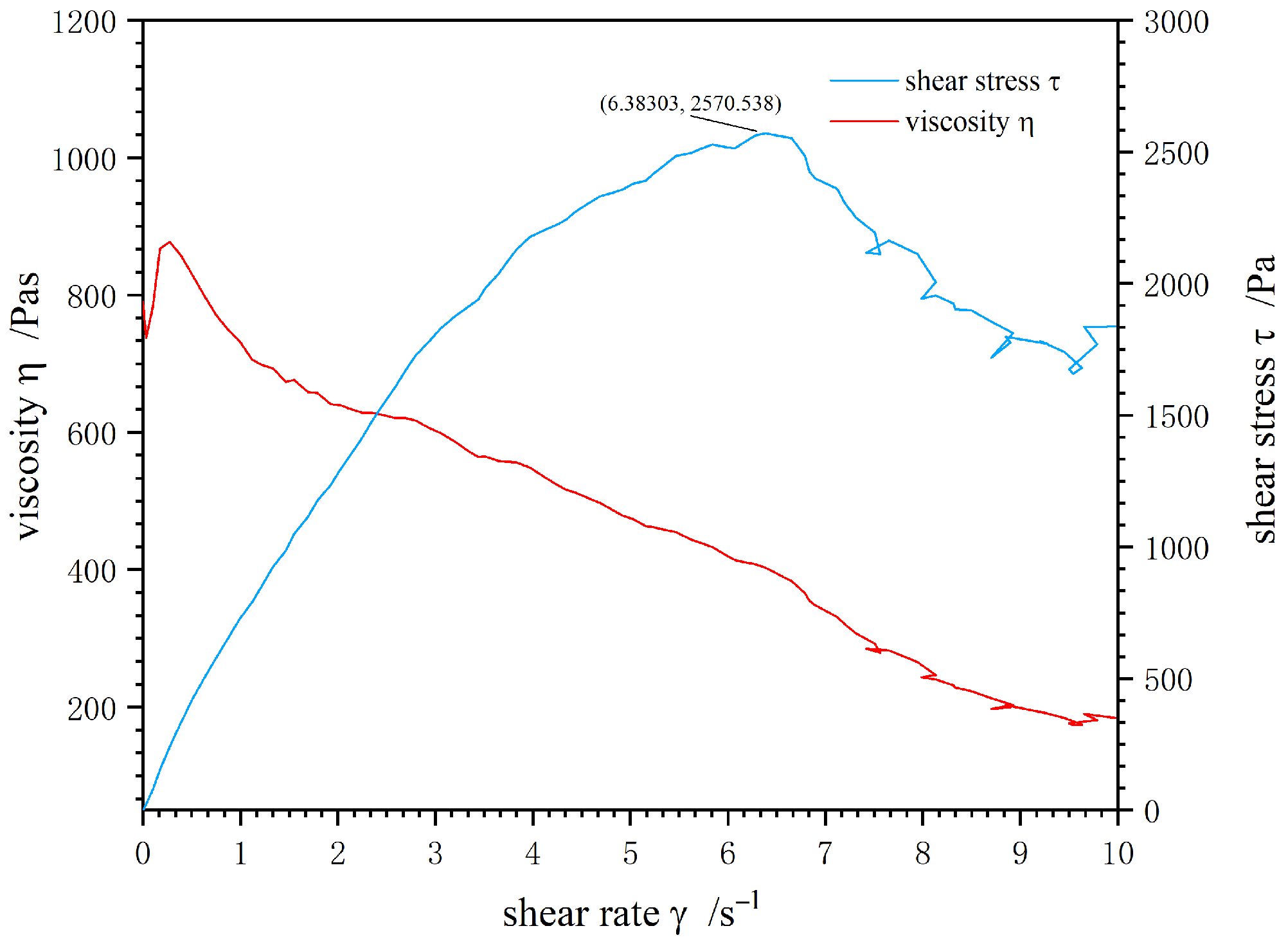
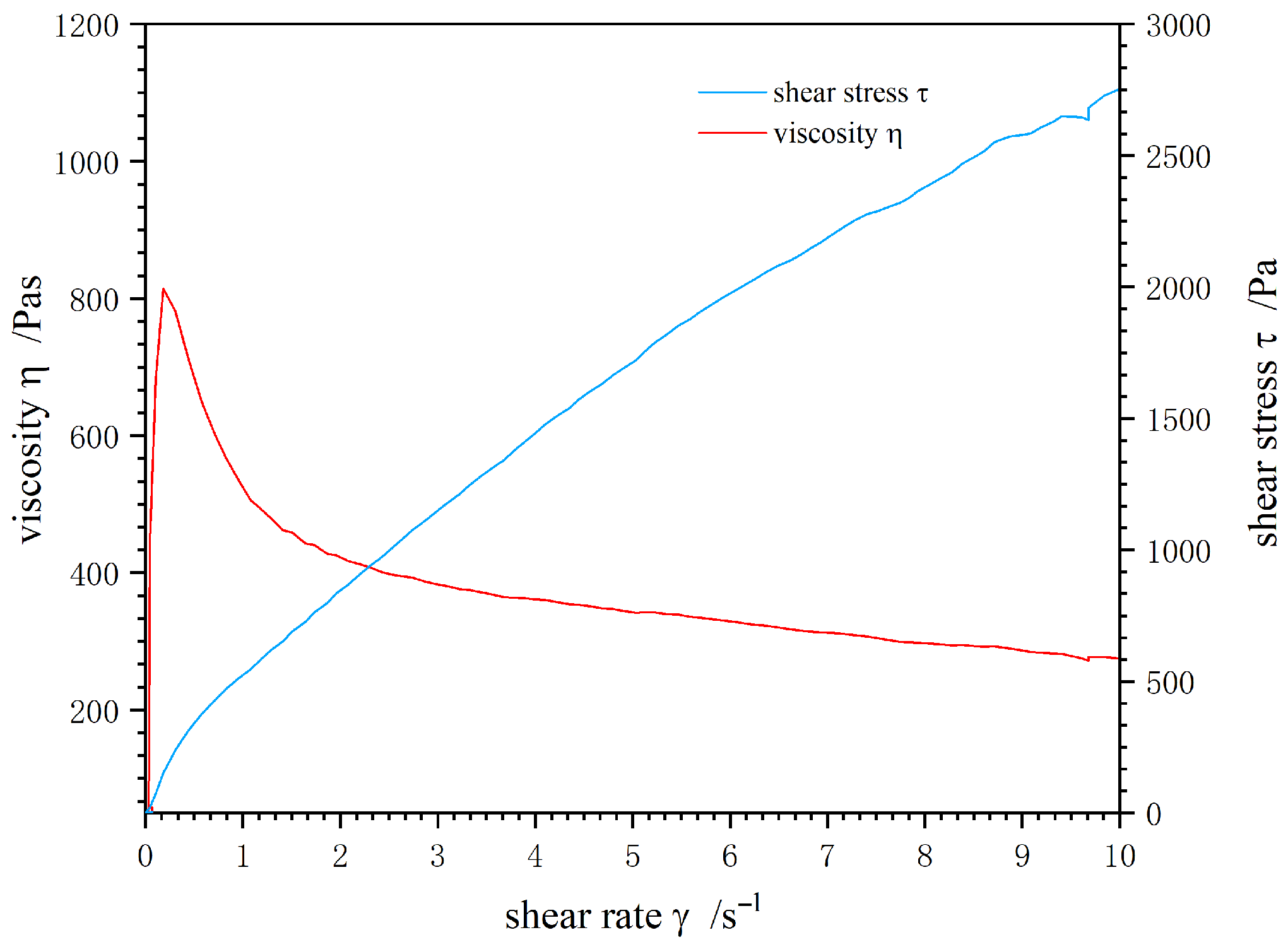
Rheological properties of the inert materials were tested using the HAAKE Viscotester IQ with the Couette system, as shown in Figure 12, Figure 13 and Figure 14.
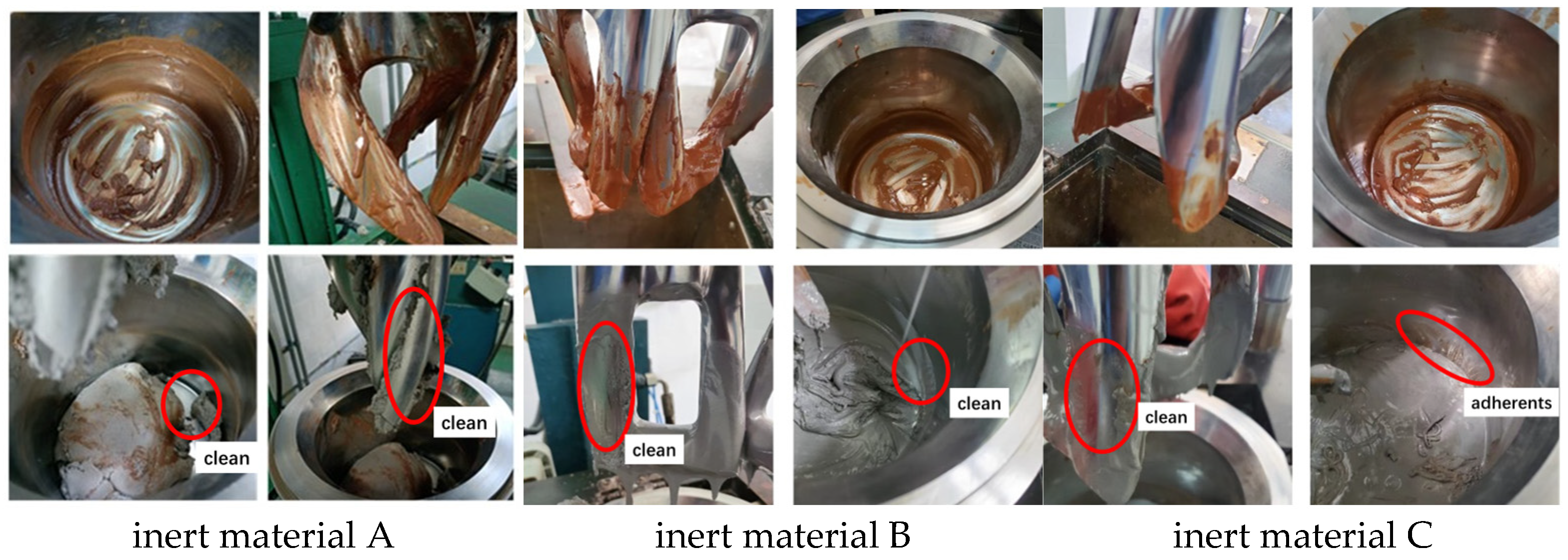
That indicates the shear stress of inert material A wall slip is 2850 Pa, the shear stress of inert material B wall slip is 2570 Pa, and the inert material C will not wall slip during the testing process. The cleaning procedure is as follows: inject three types of inert materials into the mixer with adhering high-burn-rate propellant residues, then start the equipment, set the satellite impeller speed to 80 rad/min (158 s−1), and operate continuously for 5 min. The cleaning effectiveness is visually evaluated against the following three criteria: (1) whether the impeller surfaces are clean; (2) whether there is no propellant residue on the inner wall of the mixing barrel; and (3) whether the mixture generated during cleaning is easy to collect and remove. The cleaning performance of three inert materials on the mixer with adherent high-burn-rate propellant residues is shown in Figure 15 and Table 4.
The rheological properties of inert materials can be effectively modulated by adjusting the PVC content. Aluminum powder particles exhibit a smooth surface morphology, whereas PVC particles possess a rough surface texture. Increasing the PVC proportion enhances the overall viscosity and shear stress of the mixture, as confirmed by rheological tests: Material A (35% PVC) achieves a wall slip stress of 2850 Pa, Material B (25% PVC) reaches 2570 Pa, and Material C (15% PVC) shows no wall slip due to insufficient stress. This viscosity improvement directly optimizes the cleaning efficiency by promoting wall slip behavior when the shear stress exceeds the propellant’s critical threshold (2313.6 Pa).

4. Conclusions

  • High-burn-rate propellants, as non-Newtonian fluids, exhibit wall slip behavior.
  • The stress–strain behavior of a given material remains consistent across different rheological testing systems. The extension ratio at specific test moments shows a positive correlation with the shear efficiency of the system.
  • Propellant wall slip enables manual-free cleaning of high-burn-rate/high-hazard propellant mixers using inert materials. Feasibility requires two conditions: inert materials exhibit wall slip at shear rates below the mixer’s maximum, and the applied shear stress exceeds the propellant’s critical wall slip threshold (2313.6 Pa). This approach lays a foundation for the unmanned and automated cleaning of mixers.

Author Contributions

Conceptualization, B.H. and W.D.; methodology, B.H.; software, C.Z.; validation, B.H., W.D. and C.Z.; formal analysis, W.D.; investigation, B.H.; resources, D.C.; data curation, C.Z.; writing—original draft preparation, B.H. and X.H.; writing—review and editing, W.D. and Q.S.; visualization, C.Z. and X.H.; supervision, T.Z.; project administration, T.Z.; funding acquisition, B.H. All authors have read and agreed to the published version of the manuscript.

Funding

This research received no specific grant from any funding agency in the public, commercial, or not-for-profit sectors.

Institutional Review Board Statement

Not applicable.

Informed Consent Statement

Not applicable.

Data Availability Statement

The original contributions presented in this study are included in the article. Further inquiries can be directed to the corresponding author.

Acknowledgments

The authors thank Hubei Institute of Aerospace Chemical Technology for providing experimental equipment and technical support.

Conflicts of Interest

The authors declare no conflicts of interest. The funders had no role in the design of the study; in the collection, analyses, or interpretation of data; in the writing of the manuscript; or in the decision to publish the results.

Abbreviations

The following abbreviations are used in this manuscript:
HTPBHydroxy-terminated polybutadiene
APAmmonium perchlorate
DOADioctyl adipate
IPDIIsophorone diisocyanate
PVCPolyvinyl chloride
EBMsEnergetic ballistic modifiers
ESDElectrostatic discharge
αExtension ratio
βShear efficiency
ηViscosity
τShear stress
γ ˙ Shear rate

References

  1. Takahashi, K.; Sugo, Y.; Takahata, Y.; Tanaka, T.; Suzuki, H. Laminar Mixing in a Stirred Tank Agitated by an Inclined Impeller. Int. J. Chem. Eng. 2012, 2012, 858329. [Google Scholar] [CrossRef]
  2. Wang, S.; Wu, J.; Ohmura, N. Inclined-Shaft Agitation for Improved Viscous Mixing. Ind. Eng. Chem. Res. 2013, 52, 11741–11751. [Google Scholar] [CrossRef]
  3. Wang, S.; Wu, J.; Bong, E.K. Reduced IMRs in a Mixing Tank via Agitation Improvement. Chem. Eng. Res. Des. 2013, 91, 1009–1017. [Google Scholar] [CrossRef]
  4. Kamla, Y.; Ameur, H.; Karas, A.; Bouzit, M.; Benabdelouahab, T. Performance of New Designed Anchor Impellers in Stirred Tanks. Chem. Pap. 2020, 74, 741–750. [Google Scholar] [CrossRef]
  5. Kamienski, J.; Wojtowicz, R. Dispersion of Liquid–Liquid Systems in a Mixer with a Reciprocating Agitator. Chem. Eng. Sci. 2003, 58, 2687–2697. [Google Scholar] [CrossRef]
  6. Kordas, M.; Story, G.; Konopacki, M.; Bialecka-Florjanczyk, E.; Nowakowski, P. Study of Mixing Time in a Liquid Vessel with Rotating and Reciprocating Agitator. Ind. Eng. Chem. Res. 2013, 52, 13818–13828. [Google Scholar] [CrossRef]
  7. Galletti, C.; Brunazzi, E. On the Main Flow Features and Instabilities in an Unbaffled Vessel Agitated with an Eccentrically Located Impeller. Chem. Eng. Sci. 2008, 63, 4494–4505. [Google Scholar] [CrossRef]
  8. Woziwodzki, S.; Broniarz-Press, L.; Ochowiak, M. Effect of Eccentricity on Transitional Mixing in Vessel Equipped with Turbine Impellers. Chem. Eng. Res. Des. 2010, 88, 1607–1614. [Google Scholar] [CrossRef]
  9. Woziwodzki, S. Unsteady Mixing Characteristics in a Vessel with Forward–Reverse Rotating Impeller. Chem. Eng. Technol. 2011, 34, 767–774. [Google Scholar] [CrossRef]
  10. Tong, R.; Zhao, Y.; Wang, L.; Li, J.; Zhang, H. Recent Research Progress in the Synthesis and Properties of Burning Rate Catalysts Based on Ferrocene-Containing Polymers and Derivatives. J. Organomet. Chem. 2014, 755, 16–32. [Google Scholar] [CrossRef]
  11. Fogelzang, A.E.; Denisyuk, A.P.; Egorshev, V.Y.; Shkadov, V.A. Burning Behavior of Composite Propellants with Fast-Burning Inclusions. J. Propuls. Power 2000, 16, 374–376. [Google Scholar] [CrossRef]
  12. Ramakrishna, P.A.; Ramesh, K.; Prasad, K.V.S.R. Enhancing Composite Solid Propellant Burning Rates with Potassium Doped Ammonium Perchlorate—Part 2. J. Propuls. Power 2014, 30, 987–993. [Google Scholar] [CrossRef]
  13. Cudzilo, S.; Trzcinski, W.A.; Nita, M.; Wojewódzki, A.; Chudziński, J. Preparation, Crystal Structure and Explosive Properties of Copper(II) Perchlorate Complex with 4-Amino-1,2,4-Triazole and Water. Propellants Explos. Pyrotech. 2011, 36, 151–159. [Google Scholar] [CrossRef]
  14. Talawar, M.B.; Divekar, C.N.; Makashir, P.S.; Asthana, S.N.; Singh, A. Tetrakis(4-Amino-1,2,4-Triazole) Copper Perchlorate: A Novel Ballistic Modifier for Composite Propellants. J. Propuls. Power 2012, 28, 186–189. [Google Scholar] [CrossRef]
  15. Cudzilo, S.; Nita, M. Synthesis and Explosive Properties of Copper(II) Chlorate(VII) Coordination Polymer with 4-Amino-1,2,4-Triazole Bridging Ligand. J. Hazard. Mater. 2010, 177, 146–149. [Google Scholar] [CrossRef]
  16. Ramamurthy, A.V. Wall Slip in Viscous Fluids and Influence of Materials of Construction. J. Rheol. 1986, 30, 337–357. [Google Scholar] [CrossRef]
  17. Kalika, D.S.; Denn, M.M. Wall Slip and Extrudate Distortion in Linear Low-Density Polyethylene. J. Rheol. 1987, 31, 815–834. [Google Scholar] [CrossRef]
  18. Hatzikiriakos, S.G.; Dealy, J.M. Wall Slip of Molten High Density Polyethylene. I. Sliding Plate Rheometer Studies. J. Rheol. 1991, 35, 497–523. [Google Scholar] [CrossRef]
  19. Hatzikiriakos, S.G.; Dealy, J.M. Wall Slip of Molten High Density Polyethylene. II. Capill. Rheometer Studies. J. Rheol. 1992, 36, 703–741. [Google Scholar] [CrossRef]
  20. Migler, K.B.; Hervet, H.; Léger, L. Slip Transition of a Polymer Melt Under Shear Stress. Phys. Rev. Lett. 1993, 70, 287–290. [Google Scholar] [CrossRef] [PubMed]
  21. Migler, K.B.; Massey, G.A.; Hervet, H.; Léger, L. The Slip Transition at the Polymer–Solid Interface. J. Phys. Condens. Matter 1994, 6, A301–A304. [Google Scholar] [CrossRef]
  22. Hervet, H.; Léger, L. Flow with Slip at the Wall: From Simple to Complex Fluids. C. R. Phys. 2003, 4, 241–249. [Google Scholar] [CrossRef]
  23. Kalyon, D.M.; Gevgilili, H. Wall Slip and Extrudate Distortion of Three Polymer Melts. J. Rheol. 2003, 47, 683–699. [Google Scholar] [CrossRef]
  24. Hill, D.A. Wall Slip in Polymer Melts: A Pseudo-Chemical Model. J. Rheol. 1998, 42, 581–601. [Google Scholar] [CrossRef]
  25. Hatzikiriakos, S.G. Wall Slip of Molten Polymers. Prog. Polym. Sci. 2012, 37, 624–643. [Google Scholar] [CrossRef]
  26. Abdillah, L.A.; Restasari, A.; Hartaya, K.; Wibowo, A.; Sutopo, H. The Selection of Composite Solid Propellant Process Condition Based on Flow Characteristics of Propellant Slurry. In Proceedings of the International Seminar on Aerospace Science and Technology; Bandung Institute of Technology: Bandung, Indonesia, 2020; pp. 45–52. [Google Scholar]
  27. Wu, Y.; Li, Z.; Ji, Y.-C.; Zhang, Y.; Liu, J. Experimental Study of Rheological Properties of Solid Propellant Slurry at Low-Shear Rate and Numerical Simulation. J. Appl. Polym. Sci. 2020, 137, 49287. [Google Scholar] [CrossRef]
  28. Campbell, S. The Ins and Outs of Pipeline Cleaners: Testing and Evaluation for Chemical Cleaners. In Paper NACE-00434, Presented at the CORROSION 2000 Conference; NACE International: Orlando, FL, USA, 2000; pp. 1–12. [Google Scholar]
  29. Prošek, M.; Križman, M.; Kovač, M. Evaluation of a Rinsing-Based Cleaning Process for Pipes. J. Pharm. Biomed. Anal. 2005, 38, 508–513. [Google Scholar] [CrossRef] [PubMed]
  30. Yan, H.; Niu, H.; Chang, Q.; Li, J.; Wang, Z. Study on Dynamic Characteristics of Pipeline Jet Cleaning Robot. Actuators 2024, 13, 49. [Google Scholar] [CrossRef]
  31. Gupta, G.; Jawale, L.; Mehilal, M.; Singh, A.K.; Yadav, A.K. Various Methods for the Determination of the Burning Rates of Solid Propellants—An Overview. Cent. Eur. J. Energ. Mater. 2015, 12, 593–620. [Google Scholar]
Figure 1. The schematic diagram of the mixer.
Applsci 16 02994 g001
Figure 2. Crawford bomb for the measurement of burning rate.
Applsci 16 02994 g002
Figure 4. The schematic diagram of extension ratio in two testing systems. (a) Top view of Couette testing system. (b) Front view of flat rotor testing system. The red line represents the length of the material before testing and the green line represents the length of the material after testing.
Applsci 16 02994 g004
Figure 5. The force analysis of clean process.
Applsci 16 02994 g005
Figure 6. Rheology test of high-burn-rate propellant (Couette).
Applsci 16 02994 g006
Figure 7. Rheology test of high-burn-rate propellant (parallel plate).
Applsci 16 02994 g007
Figure 8. Rheology test of the sample propellant-1 (Couette).
Applsci 16 02994 g008
Figure 9. Rheology test of the sample propellant-2 (parallel plate).
Applsci 16 02994 g009
Figure 10. Rheology test of the sample propellant-2 (Couette).
Applsci 16 02994 g010
Figure 11. Rheology test of the sample propellant-2 (parallel plate).
Applsci 16 02994 g011
Figure 12. Rheology test of the inert material A (Couette).
Applsci 16 02994 g012
Figure 13. Rheology test of the inert material A (Couette).
Applsci 16 02994 g013
Figure 14. Rheology test of the inert material A (Couette).
Applsci 16 02994 g014
Figure 15. The cleaning performance of three inert materials.
Applsci 16 02994 g015
Table 1. Summary of ESD, impact, and friction sensitivity.
ESD Ignition Energy (mJ)BAM Fallhammer Impact Energy (J)WM-1 Friction Explosion Rate (%)
2610.5100
Table 2. Summary of calculation results (sample propellant-1).
The Key Point ηmaxThe Key Point Wall Slip
L/mmαL/mmα
parallel plates 1.8411.22788.69959.133
Couette1.9101.91093.75793.757
β (c/p)1.5571.586
Table 3. Summary of calculation results (sample propellant-2).
The Key Point ηmaxThe Key Point Wall Slip
L/mmαL/mmα
parallel plates 7.8745.249111.76074.507
Couette10.94010.940153.559153.559
B (c/p)2.0842.061
L denotes the stretched length of the material post-shearing (green line in Figure 4), while α represents the stretch ratio—defined as the ratio of the green segment to the red segment in Figure 4.
Table 4. Results of cleaning effects of three inert materials.
No.Evaluation ItemEvaluation CriteriaInert Material
ABC
1Impeller surface cleanlinessNo high-burn-rate propellant residues, visible stains, or adherents on the impeller surfaces+++
2Residue status on the inner wall of the mixing barrelNo visible high-burn-rate propellant residues on the inner wall of the mixing barrel, with a smooth surface free of adhesion marks++-
3Handleability of the cleaned mixtureThe mixture generated during cleaning is in a loose state, without strong adhesion, and easy to collect and completely remove+--
The shear stress of wall slip2850 Pa2570 Pa-
Disclaimer/Publisher’s Note: The statements, opinions and data contained in all publications are solely those of the individual author(s) and contributor(s) and not of MDPI and/or the editor(s). MDPI and/or the editor(s) disclaim responsibility for any injury to people or property resulting from any ideas, methods, instructions or products referred to in the content.