Article

Damage Characteristics of Rock Mass Under Cutting Blasting in Sharp Inclined Narrow Vein Mines

1
School of Resources and Safety Engineering, Central South University, Changsha 410083, China
2
Hunan Gold Tianyue Mining Co., Ltd., Yueyang 414500, China
*
Author to whom correspondence should be addressed.
Appl. Sci. 2026, 16(6), 2980; https://doi.org/10.3390/app16062980
Submission received: 22 January 2026 / Revised: 15 March 2026 / Accepted: 18 March 2026 / Published: 19 March 2026
(This article belongs to the Topic Failure Characteristics of Deep Rocks, 3rd Edition)

Abstract

In the drift mining of sharp, inclined, narrow veins, the efficacy of cutting blasting directly governs the efficiency of blasting operations. However, the mechanisms of rock mass damage and fracturing induced by cutting blasting in sharp inclined narrow vein mines remain inadequately understood. This study employs a 3D numerical model of cutting blasting calibrated with field test data to analyze the damage and fracture processes of rock mass under cutting blasting in sharp inclined narrow vein mines. A parametric study further examines the effects of vein thickness and in situ stress on blast-induced damage and fracturing of a rock mass. The results show that cutting blasting produces a significantly asymmetric damage distribution in sharp, inclined, narrow vein mines. Under conditions of small vein thickness, the propagation of damage along the vein–rock interface increases, and the clamping effect on the rock in the cutting blasting zone intensifies. Additionally, high bidirectional equal in situ stress substantially suppresses blast-induced damage development, with the suppression intensity showing a positive correlation to in situ stress magnitude. The findings provide a theoretical basis for cutting blasting design in the drift mining of sharp inclined narrow veins.

1. Introduction

Sharp, inclined, narrow veins serve as important carriers of strategic mineral resources such as gold, silver, tungsten, and tin [1,2,3,4]. The drift mining method represents a commonly employed approach in sharp, inclined, narrow vein mines. In drift mining, cutting blasting constitutes the crucial step for creating the initial breakage compensation space [5,6,7]. Cutting blasting performance governs the efficiency of subsequent mining cycles and even influences the economic indicators of the mining operation [8,9,10,11]. However, the challenging geological features of confined spaces translate directly into severely constrained blasting energy distribution and consequent issues of uncontrolled blasting performance [12,13]. Therefore, investigation of the rock mass damage and fracture under cutting blasting becomes particularly crucial for optimizing blasting design and enhancing mining efficiency in sharp, inclined, narrow vein mines.
Limited research has been conducted on the blasting performance in narrow vein mines. For instance, An et al. [1] conducted a study on the blasting performance under narrow vein mining by combining the PFC and LS-DYNA numerical modeling programs and found that the restricted free surfaces significantly increase the difficulty of blast crater formation. Vishwakarma et al. [13] conducted a numerical investigation on the optimum burden for the excavation of narrow veins, demonstrating that the optimum burden increases with the decrease in width of the ore body. Zhang et al. [2] proposed a modified Scaled Heelan-based method that accounts for free surface effects to evaluate blast-induced damage and fragmentation. Their analysis demonstrated that within a certain range, both damage volume and fragment size exhibit positive correlations with free surface width and burden. However, the current understanding of blast-induced damage in narrow vein mining is predominantly based on studies conducted in shallow rock masses.
As shallow mineral resources become increasingly depleted, mining operations are progressively extending to greater depths, where the influence of high in situ stresses on blasting performance becomes significantly more pronounced [14,15,16,17,18]. The interaction between the in situ stress and blast loading generates strong coupling effects that significantly alter the fracture behavior and damage distribution of the rock mass [19,20,21,22]. Numerous studies have confirmed that the in situ stress significantly suppresses blast-induced fracture propagation [23,24,25,26,27,28]. Moreover, blast-induced fractures tend to preferentially develop along the direction of the maximum principal stress, whereas fractures perpendicular to this direction are substantially shortened [29,30,31,32,33]. Under non-uniform high stress, blast-induced damage exhibits pronounced anisotropy, with both crack density and length diminishing as in situ stress increases [34,35,36,37]. While existing research has extensively investigated the influence of in situ stress on rock mass damage, the coupled effect between high in situ stress and narrow vein boundaries in the rock mass damage under cutting blasting remains unexplored.
Therefore, this study aims to investigate rock mass damage induced by cutting blasting in sharp inclined narrow vein mines through numerical simulation. First, a three-dimensional numerical model of cutting blasting under a sharp, inclined, narrow vein mine is established and calibrated through in situ blasting tests. Subsequently, the damage evolution process of rock masses during cutting blasting in sharp, inclined, narrow vein mines is analyzed. Finally, the influence of vein width, in situ stress and detonation position on rock mass damage and fracture under cutting blasting is examined. The findings are expected to provide theoretical guidance for optimizing cutting blasting parameters in the drift mining of sharp inclined narrow vein mines.

2. Engineering Background

2.1. Overview

The field test is conducted at Jiangdong gold mine in China, which currently employs the upward horizontal slicing and drift filling mining method. The main vein is located and has a strike length of over 1500 m. The vein exhibits typical sharp inclined characteristics, with dip angles ranging from 50° to 68° and averaging 60°. Vein thickness varies considerably between 0.66 m and 14.43 m, demonstrating significant variation characteristics. The surrounding rock in the test section is mainly composed of slate. The in-situ stress of this mine is determined using the re-oriented core acoustic emission method [38], which combines the non-oriented core ground re-orientation and Kaiser effect. By this method, the relationship between the in-situ stress of the Jiangdong gold mine and the burial depth h is determined, including vertical principal stress σv = 0.0265h + 2.05, maximum horizontal principal stress σhmax = 0.0372h + 2.91, minimum horizontal principal stress σhmin = 0.0214h + 2.76. Through laboratory mechanical testing, the fundamental physical and mechanical parameters of the slate are determined as follows: density of 2552 kg·m−3, compressive strength of 77.56 MPa and tensile strength of 9.23 MPa.

2.2. Single-Hole Blasting Test

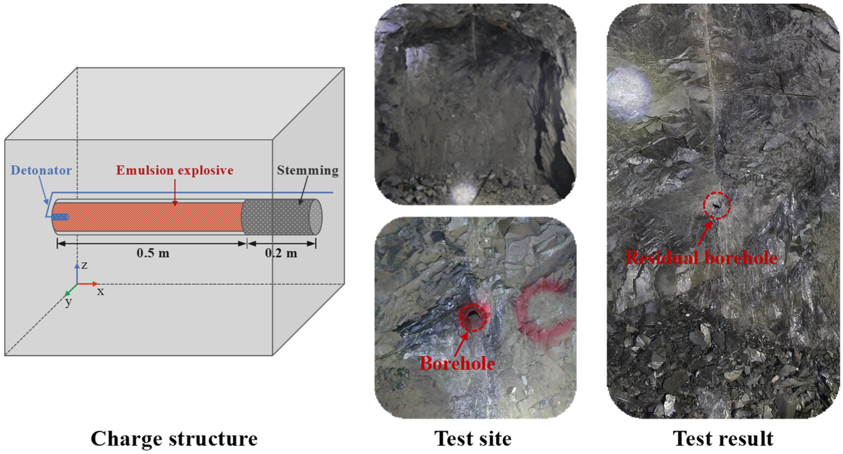
A single-hole blasting field test was conducted in this underground gold mine. The test was carried out in a development drift with stable surrounding rock. Figure 1 details the layout of the single-hole blasting test. A vertical borehole with a diameter of 40 mm and a depth of 0.7 m was drilled at the center of the excavation surface. Packaged emulsion explosives with a diameter of 32 mm were continuously loaded at the bottom of the borehole, resulting in a charge length of 0.5 m. A 0.2 m stemming was tightly sealed, guaranteeing efficient blast energy confinement. The bottom initiation method was employed by positioning the detonator at the bottom of the explosive charge. After blasting, on-site observations revealed that a typical blast cavity formed at the excavation face. The contour of the blast cavity was measured using a grid method [39]. Transverse and longitudinal measurement lines with a spacing of 0.1 m were established, and the depth at each intersection point was recorded. The cavity contour was then reconstructed in post-processing software based on these point cloud data. Through measurement, the residual drilling depth was 0.35 m, and the average top diameter of the blast cavity reached 0.68 m.

3. Numerical Model

In this study, the LS-DYNA finite element software (LS-DYNA R8.1.0) [40] is selected to accurately simulate the damage and fracture process of rock mass under cutting blasting in steeply inclined narrow vein mines. First, a three-dimensional numerical model of cutting blasting under a sharp inclined narrow vein mine is established, and material model parameters are determined. Then, the model is calibrated based on results from single-hole blasting tests. The details are as follows.

3.1. Numerical Modeling

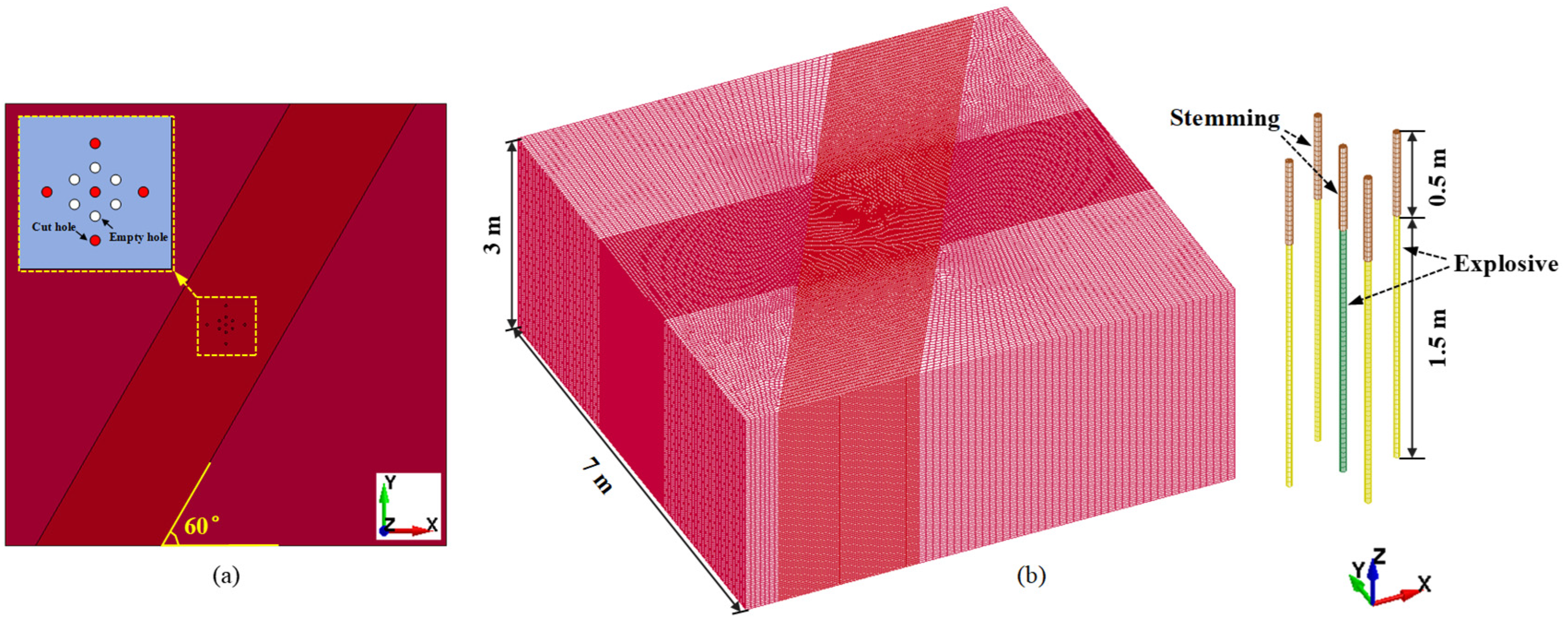
This study establishes a three-dimensional numerical model of cutting blasting in a sharp, inclined, narrow vein mine. Figure 2 illustrates the geometric configuration. The numerical model strictly adheres to field geological conditions with a vein dip angle of 60° and overall dimensions of 7 m × 7 m × 3 m, while comprehensively accounting for blast influence range and boundary effects. The configuration includes five cut holes and six empty holes, all with a 40 mm diameter and 2 m depth. Cut holes contain 1.5 m long explosive charges. The borehole arrangement follows a concentric rhombic symmetric pattern, i.e., one central cut hole surrounded by four symmetrically distributed auxiliary cut holes. Six empty holes were uniformly distributed between the central and peripheral cut holes. The spacing measures 30 cm between central and peripheral cut holes, and similarly 12 cm between central blast holes and empty holes. The simulation employs reverse initiation sequencing, detonating the central blast hole first, followed by peripheral cut holes.
Meshing strategy implements a graded refinement scheme with progressive coarsening to optimize computational accuracy and efficiency. A fine mesh of 6 mm was deployed in the cut hole vicinity to precisely capture blast-induced damage propagation and fracture development, while a transition mesh of 90 mm was applied to peripheral regions. The final discretization yields approximately 3,700,000 elements and 3,800,000 nodes, maintaining computational tractability. For accurate simulation of underground drift excavation, the model configuration incorporates a free surface boundary at the top surface to represent the stope face, with non-reflecting boundaries applied to the bottom and side surfaces to simulate stress wave propagation in infinite rock media. The non-reflective boundary condition can effectively absorb the stress waves at the artificial boundary, avoiding the interference of reflected waves on the rock mass damage under cutting blasting. This method has been verified in numerous numerical simulation studies of rock mass blasting [30,41]. Numerical simulation utilizes the multi-material Arbitrary Lagrangian–Eulerian (ALE) algorithm to precisely simulate dynamic interactions among explosive, air and rock materials. Overlapping layer elements between air and rock ensure efficient energy transfer. It should be noted that the present numerical model idealizes the rock mass as a continuous, two-component medium. In natural narrow vein mines, ore veins are typically associated with pre-existing discontinuities, which can significantly influence stress wave propagation and blast-induced fracture patterns. However, explicit modeling of complex discontinuity networks requires detailed geological data that are not available in this study. Therefore, the current continuous-medium representation focuses on the influence of vein thickness on blasting response.

3.2. Material Models and Parameters

In the numerical simulation of rock mass blasting, the selection of the material constitutive model directly affects the accuracy and reliability of the numerical calculation results. Currently, constitutive models such as the HJC mode [42], RHT model [30,43] and K&C model [44] have been widely used to describe the dynamic response behavior of rock materials under blasting loading. After a comprehensive comparison of various constitutive models, this study finally selects the RHT model to describe the dynamic mechanical behavior of rock mass. The RHT model describes the mechanical response of rock masse under blasting loading through three independent limit surface systems, i.e., the elastic limit surface, the failure surface and the residual strength surface [45]. The multi-limit surface enables the model to accurately reflect the complete process of rock masses from elastic deformation to complete failure. More importantly, this model simultaneously considers key physical mechanisms such as strain rate effect, confining pressure and compression hardening [45]. These advantages make the RHT model particularly suitable for simulating the damage evolution of rock mass under cutting blasting in sharp, inclined, narrow vein mines.
The RHT model consists of 37 independent parameters. The basic mechanical parameters of the RHT model are determined through laboratory tests on rock samples, including density, elastic modulus, Poisson’s ratio, compressive strength, tensile strength and wave velocity. The key parameters are calculated based on the empirical equations established by Wang et al. [23], and the reliability of this method has been verified in multiple publications [23,46]. The remaining parameters are standardized and assigned values based on existing research results [45]. The specific determination process of the RHT model parameters is detailed in the study by Wang et al. [23]. In the numerical model, the mechanical property differences between the surrounding rock and the ore rock in sharply inclined narrow vein mines are taken into account. The mechanical parameters of the surrounding rock are determined through laboratory rock mechanics tests, as presented in Section 2.1. For the ore rock, a parameter reduction approach is adopted to account for the typical presence of joints, which result in degraded mechanical properties compared to the intact rock mass. Specifically, the rock mass classification [BQ] values for the surrounding rock and ore rock are 319 and 146, respectively. The reduction factor for the parameters of ore rock is defined as the ratio of these two [BQ] values, yielding a factor of approximately 0.46. This reduction method is applied to characterize the comparatively weaker mechanical response of the ore vein, which is attributed to the prevalence of joints and discontinuities typically observed in narrow veins. Due to the difficulty of obtaining intact vein samples from the field, direct laboratory testing of the dynamic mechanical properties of the ore vein is not feasible. Therefore, the BQ-based reduction approach is employed to approximate the relative mechanical contrast between the surrounding rock and the ore vein. The RHT model parameters for both the surrounding rock and the ore rock are then determined by combining the obtained mechanical parameters with the empirical formulas. In this parameterization, the surrounding rock and ore rock differ only in those parameters derived from the empirical relationships, while all other parameters maintain identical values. It should be noted that this parameterization aims to represent the relative mechanical contrast between the vein and the surrounding rock rather than to reproduce the exact dynamic properties of the ore vein. Although the dynamic impedance of the ore vein is not independently measured, the adopted parameter reduction still introduces a mechanical contrast, enabling the model to capture the qualitative characteristics of stress wave interaction and damage evolution near the vein–rock interface. The complete set of RHT model parameters for the surrounding rock and ore rock is summarized in Table 1 and Table 2.
In LS-DYNA, the explosive material is modeled using the *MAT_HIGH_EXPLOSIVE_BURN constitutive model, coupled with the Jones–Wilkins–Lee (JWL) equation of state. The *EOS_JWL accurately describes the pressure–volume–energy relationship of the detonation products, providing a comprehensive prediction of explosion pressure, which makes it widely used in high-explosive simulation.
P = A 1 ω R 1 V e R 1 V + B 1 ω R 2 V e R 2 V + ω E 0 V
where P is the detonation pressure, V is the relative volume, E0 is the energy per unit volume of the explosive, A, B, R1, R2, ω are the material parameters. *EOS_JWL parameters are mainly derived from the study by Yang et al. [47], who used the same explosive type in their study. As EOS_JWL parameters characterize the pressure–volume–energy relationship of the detonation products and are governed primarily by the properties of the explosive, directly adopting the parameters from Yang et al. [47] is justified. The EOS_JWL parameters are: A = 214.4 GPa, B = 0.182 GPa, R1 = 4.2, R2 = 0.9, ω = 0.15, E0 = 4.192 GPa. Explosive parameters density ρ = 1120 kg·m−3, Velocity of detonation d = 4200 m·s−1, Pcj = 9.7 GPa.
For the air material, the *MAT_NULL material model is employed in combination with the *EOS_LINEAR_POLYNOMIAL. This modeling approach treats air as an ideal compressible fluid, with the polynomial coefficients configured to accurately capture the dynamic response of air under blasting loading.
P = C 0 + C 1 μ + C 2 μ + C 3 μ + C 4 + C 5 + C 6 μ E μ = ρ ρ 0 1
where P is the gas pressure, E is the internal energy per unit volume, μ is the dynamic viscosity coefficient, C0, C1, C2, C3, C4, C5 and C6 are constants. μ can be determined by ρ and ρ0, ρ and ρ0 are the density and initial density of the material, respectively. C0 = C1 = C2 = C3 = C6 = 0, C4 = C5 = γ − 1, γ is specific heat coefficient 1.4. The air density and initial internal energy are 1.290 kg·m−3 and 250,000 J·m−3, respectively.

3.3. Model Calibration

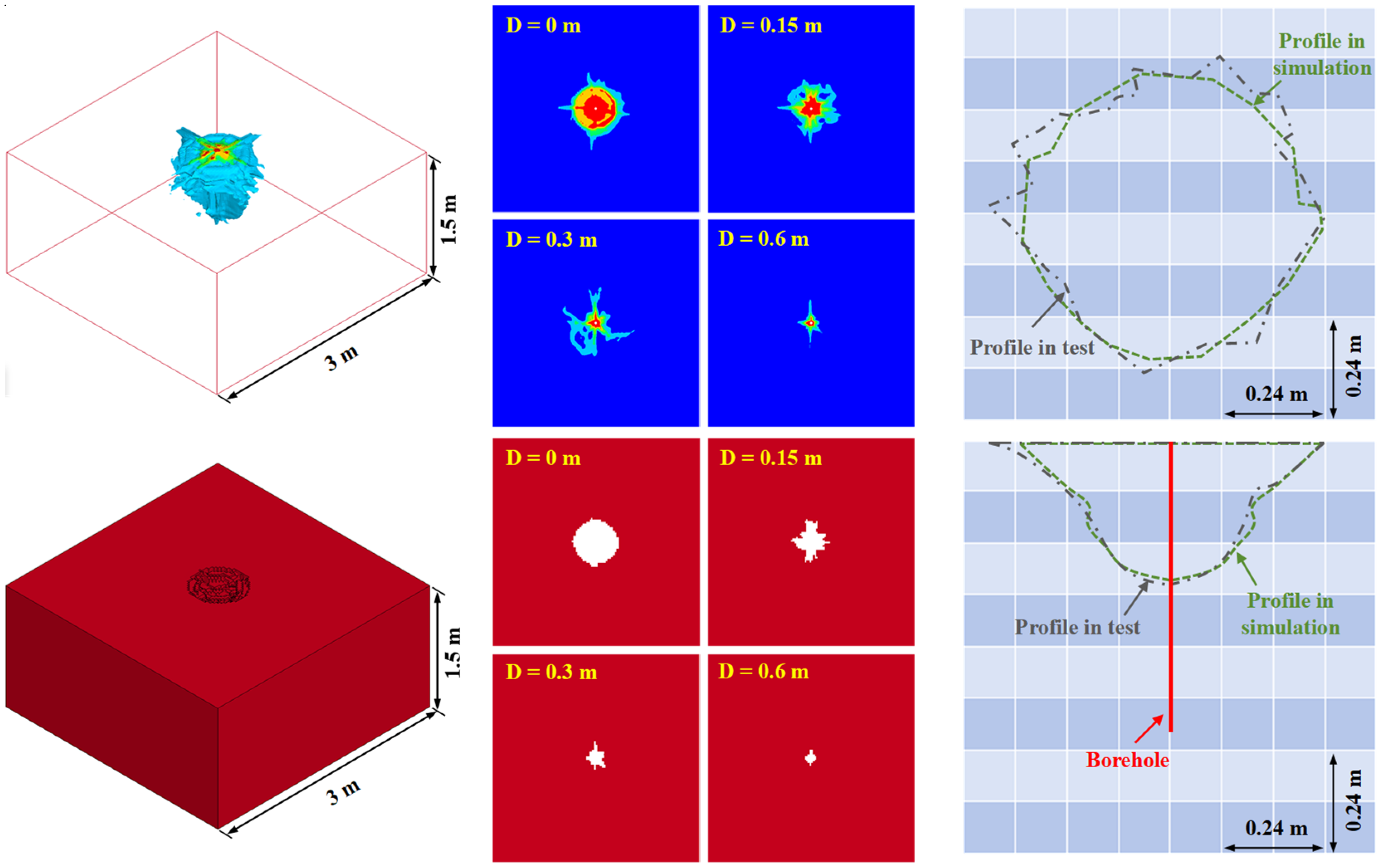
To ensure the numerical model accurately captures the rock mass damage process during cutting blasting in sharp, inclined, narrow vein mines, the model is calibrated using data from a single-hole blasting test. A corresponding numerical model is developed to replicate the actual field conditions, with dimensions of 3 m × 3 m × 1.5 m. The charge structure and parameters in the model strictly followed the experimental setup. A comparison between the cross-section of the measured blasting cavity from the test and the damage contour from the numerical simulation is presented in Figure 3. The geometry of the blast cavity is documented using a manual measurement approach, which is described in Section 2.2. The simulated cavity contour is obtained using the element deletion method based on the RHT model [48]. This study sets the damage threshold to 0.45. Once the damage in a rock element reaches this damage value (i.e., 0.45), the element is considered to have lost its load-bearing capacity and a macroscopic fracture forms, thereby replicating the formation process of the blasting cavity in the numerical model. Further numerical analysis shows that when the depth exceeds 0.34 m (e.g., under the 0.6 m condition), blasting energy concentrates near the borehole, forming a fragmentation zone rather than an effective blasting cavity. The comparison is made between the average diameters (with a difference of 0.03 m) and the depths (with a difference of 0.01 m) of the two. However, some discrepancies are noted in the top part of the cavity, where the actual blasting cavity is slightly larger than the simulated result. These differences are primarily attributed to the activation and extension of pre-existing joints in the rock mass under blasting loading, which significantly influences the failure range. Despite these variations, the simulation still provides a reliable representation of the overall blasting cavity, offering reliable insights into the damage mechanisms induced by blasting.

4. Results and Discussion

This section presents the numerical results of damage of rock mass under cutting blasting in sharp inclined narrow vein mines. The influence of two critical factors, i.e., vein thickness and in situ stress, on the cutting blasting performance in sharp, inclined, narrow vein mines is devoted to a detailed analysis. On this basis, an optimized blast parameter is proposed as a strategy for achieving efficient cutting blasting in sharp, inclined, narrow vein mines under high in situ stress.

4.1. Rock Damage Induced by Cutting Blasting in Sharp, Inclined, Narrow Vein Mines

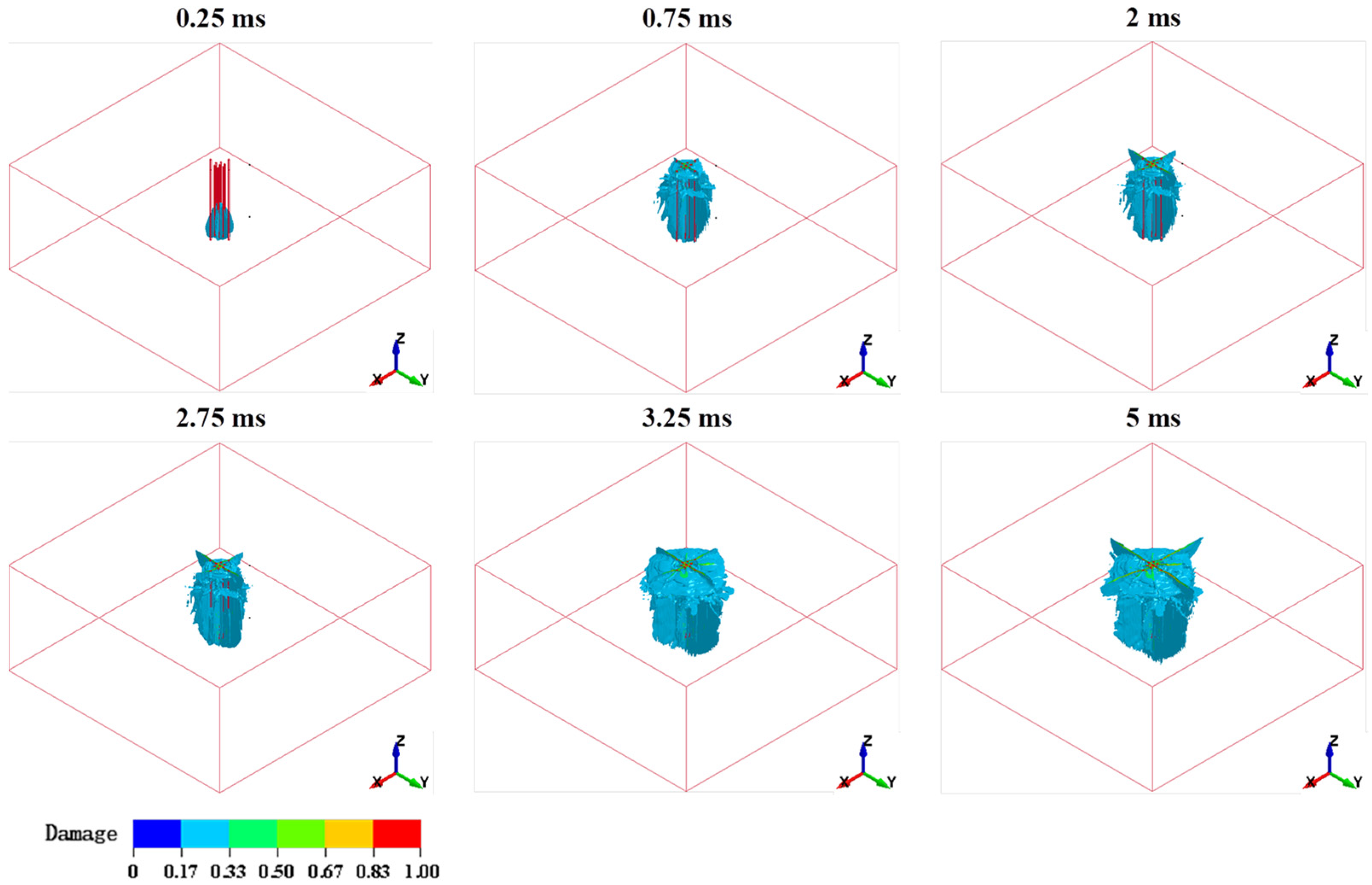
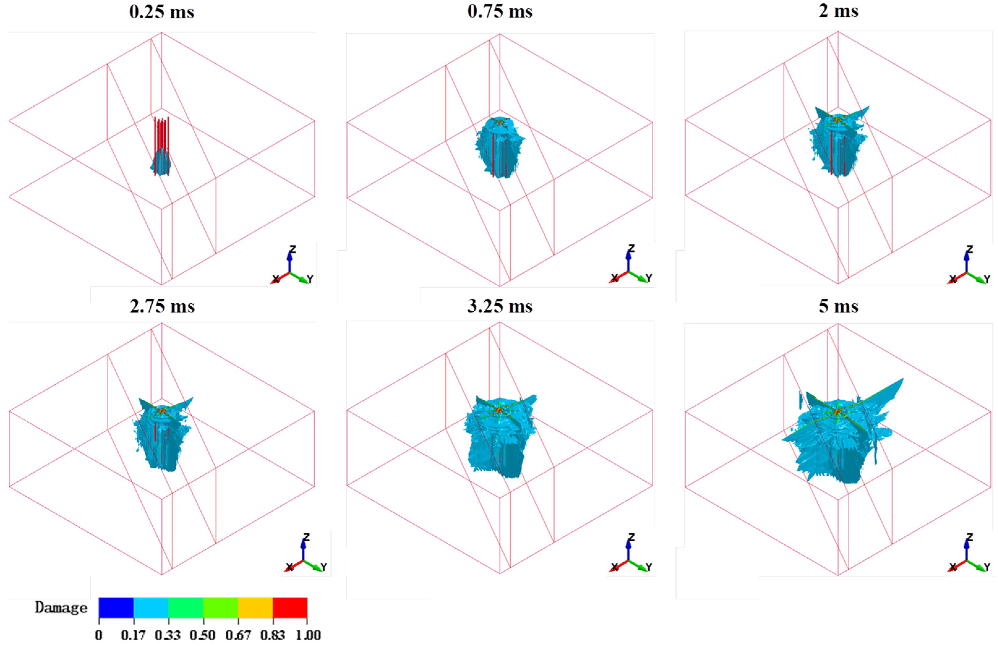
To examine the influence of vein thickness and in situ stress on cutting blasting performance, a reference model under a homogeneous rock mass is established. Two numerical models are established using identical blasting parameters, with one representing a sharp inclined 2 m thin vein with a dip angle of 60° and the other consisting of homogeneous rock for comparison. Figure 4 illustrates the evolution of damage during cutting blasting in homogeneous rock. In the initial stage (t = 0.25 ms), the shock wave from the explosive detonation at the bottom of the central cut hole rapidly induces a high-damage zone in the surrounding rock. As the stress wave propagates, the damage area expands axially along the borehole. Upon reaching the free surface, the reflected tensile wave generates a new damage area near the free surface, significantly altering the initial damage distribution pattern. After 2.5 ms, the four peripheral cut holes are detonated, further expanding and interconnecting the damaged area within the cut cavity. At 5 ms, the damage area stabilizes and a fully developed cut cavity is formed.
Figure 5 illustrates the evolution of rock mass damage during cutting blasting in sharp, inclined, narrow vein mines. Compared to the damage in the homogeneous rock model, the damage development shows notable differences. In the homogeneous rock, the damage area exhibits a symmetric distribution. In contrast, in sharply inclined narrow vein mines, the complex behavior of stress waves at the vein interface results in a distinctly asymmetric damage distribution, along with a larger damage extent compared to the damage in homogeneous rock.
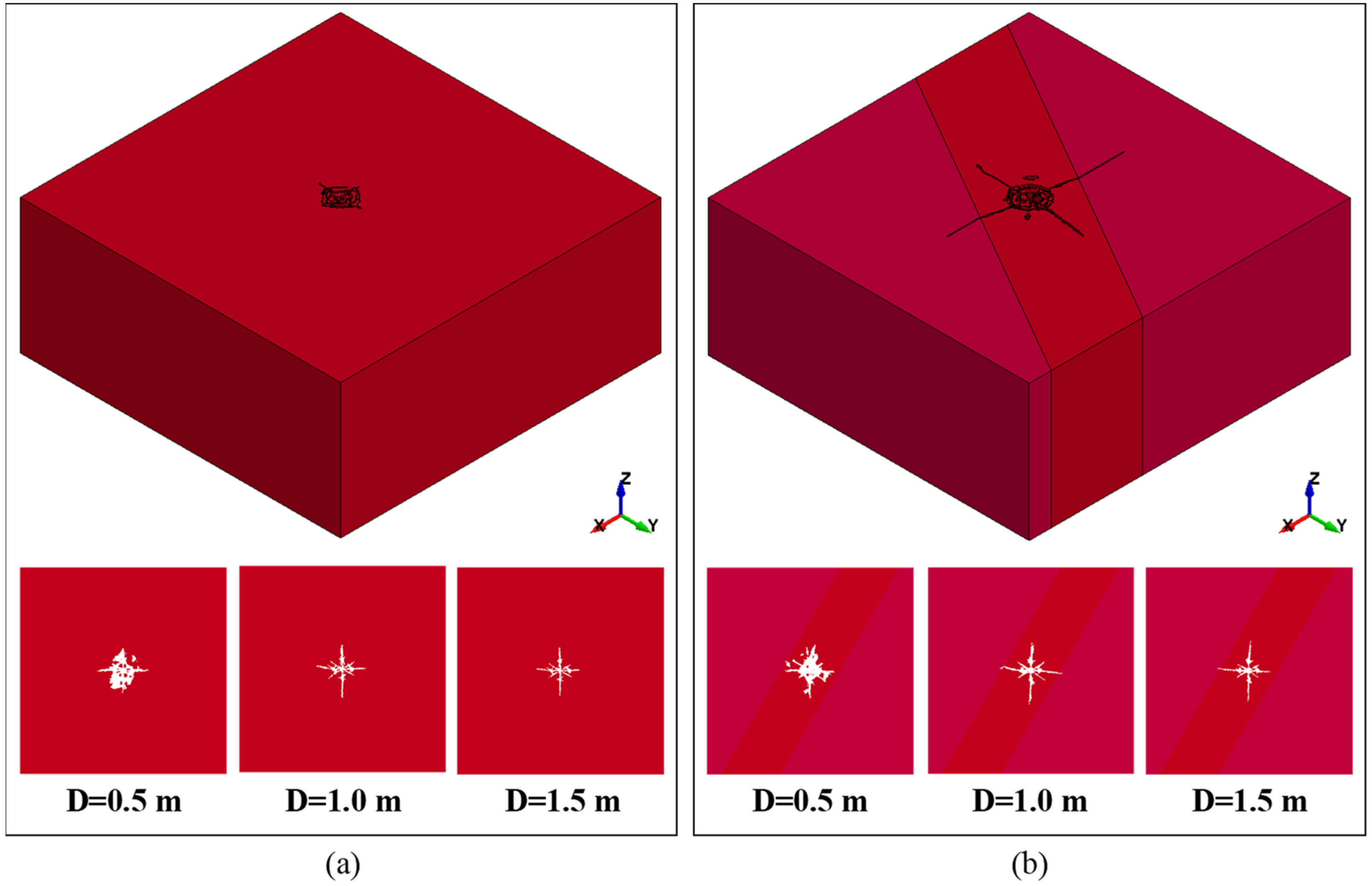
Figure 6 compares the rock fracture patterns induced by cutting blasting under two conditions: homogeneous rock and a sharp, inclined, narrow vein mine. In the homogeneous rock, blast energy propagates uniformly in a radial pattern, resulting in a symmetrically distributed fracture network. In the presence of a sharp, inclined, narrow vein mine, the fracture becomes markedly asymmetric. Four fractures are clearly visible on the outer side of the main cutting blasting area. This contrast demonstrates that the sharp, inclined, narrow vein alters stress wave propagation, imparting distinct directional characteristics to rock fracture during cutting blasting.
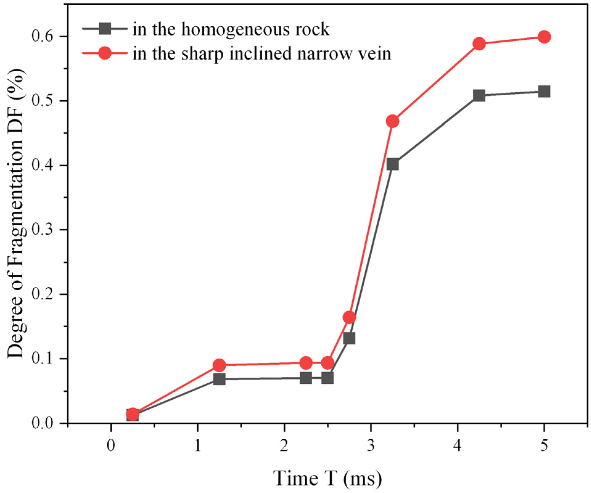
At present, there are various quantitative indicators for characterizing the degree of rock fragmentation, including fractal dimension and fragmented volume [23,49]. While fractal dimension describes fracture surface complexity, it does not directly reflect the total volume of fragmented rock mass. Therefore, fragmentation volume is selected as the core evaluation index in this study. In numerical simulations, fragmentation volume could be quantified, where an element is counted as effective fragmentation volume once its damage variable reaches the critical value of 0.45. The degree of rock fragmentation, which is defined as the ratio of fragmented rock volume to total rock volume, is widely employed to evaluate blasting performance [23]. Figure 7 illustrates the evolution of rock fragmentation degree under two conditions, i.e., homogeneous rock and a sharply inclined narrow vein. Under blasting loading, rock fragmentation evolves in a typical nonlinear growth pattern over time. At 0 ms, detonation of the central cut hole causes a rapid initial increase in fragmentation degree. As time progresses, the growth rate gradually slows. At 2.5 ms, the surrounding cut holes detonate, fragmenting a large volume of rock and driving another rapid increase in fragmentation degree. By 5 ms, the rock fragmentation degree stabilizes. Comparison of the two cases reveals that the sharply inclined narrow vein yields a relatively higher degree of rock fragmentation. This difference is attributed to the more pronounced confinement effect in homogeneous rock mass, which restricts blast-induced rock fragmentation.

4.2. Effect of Vein Thickness on Rock Damage Induced by Cutting Blasting in Sharply Inclined Narrow Vein Mines

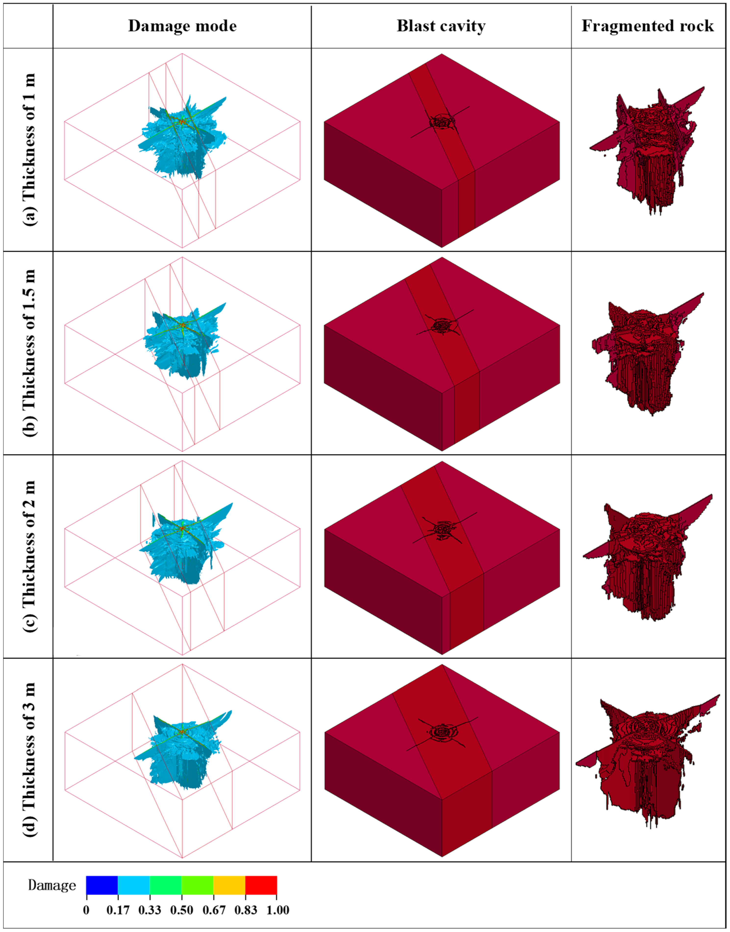
To investigate the influence of vein thickness on rock damage induced by cutting blasting in sharp, inclined, narrow vein mines, four vein thickness conditions (i.e., 1 m, 1.5 m, 2 m and 3 m) were established for comparative analysis. The vein inclination angle was maintained at 60°, consistent with actual mining. Figure 8 and Figure 9 present the blast-induced rock mass damage and fracture patterns under different vein thicknesses. The results demonstrate that vein thickness significantly affects both the distribution of rock damage and the characteristics of fracture networks. As vein thickness decreases to 1 m, the damaged area becomes concentrated along the vein–rock interface. This phenomenon results from complex stress wave behavior at the interface, where wave reflection and the contrast in mechanical properties between the vein and rock promote crack propagation along the interface, forming boundary-aligned damage. However, the concentration of damage along the vein–rock interface does not necessarily indicate improved fragmentation. As shown in Figure 9, in narrow vein mining, the surrounding rock may impose the clamping effect, suppressing effective cut cavity formation. As a result, blasting energy may be preferentially consumed in fracturing the interface zone rather than in fragmenting and ejecting the rock within the cut cavity. Although this increases the damage level near the interface, it does not necessarily improve the rock within the cut cavity removal efficiency. Moreover, as vein thickness increases, the influence of the interface gradually diminishes. A similar phenomenon is also observed in tunnel blasting construction in rock with a weak interlayer, where it is found that the presence of the weak interlayer leads to a non-uniform distribution of rock damage [50].
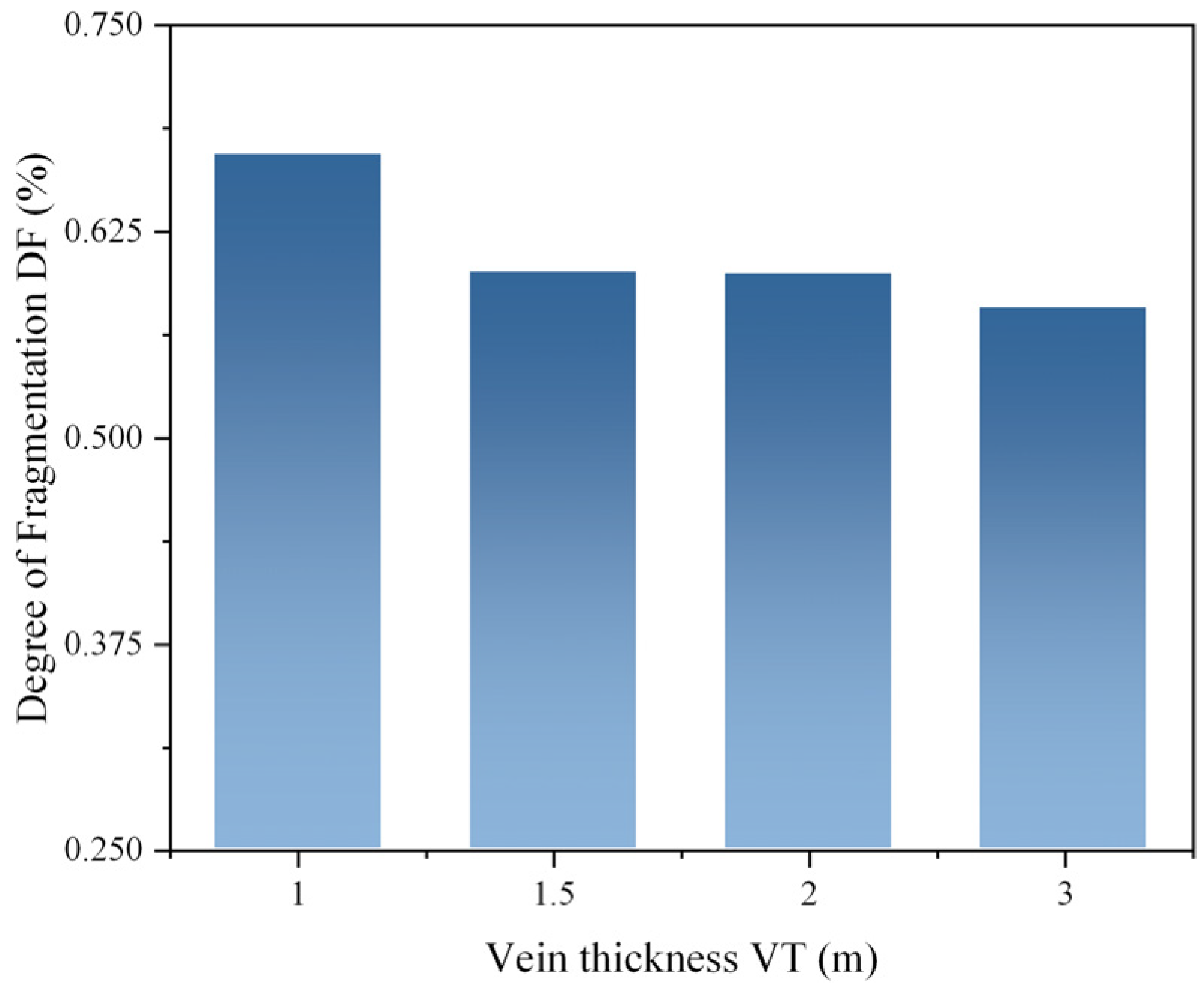
Figure 10 presents the degree of rock fragmentation at the final moment under cutting blasting under different vein thicknesses. The results reveal a nonlinear relationship between vein thickness and rock fragmentation degree. As vein thickness increases from 1 m to 3 m, the rock fragmentation degree displays a trend of rapid decline followed by stabilization. Specifically, when the thickness increases from 1 m to 1.5 m, the rock fragmentation degree decreases markedly from 0.672 to 0.6, representing a reduction of 10.7%. In contrast, as thickness further increases from 1.5 m to 3 m, the fragmentation degree declines only gradually from 0.6 to 0.579, corresponding to a reduction of 3.5%. It is worth noting that the degree of rock fragmentation mentioned above is obtained by statistically analyzing all the fragmented rock units, which also includes the fragmented rocks on the outer side of the blast zone. Based on the restraining effect of the narrow veins on the cut cavity shown in Figure 9, it can be concluded that the damage at the vein–rock interface during the mining of narrow veins cannot be ignored.
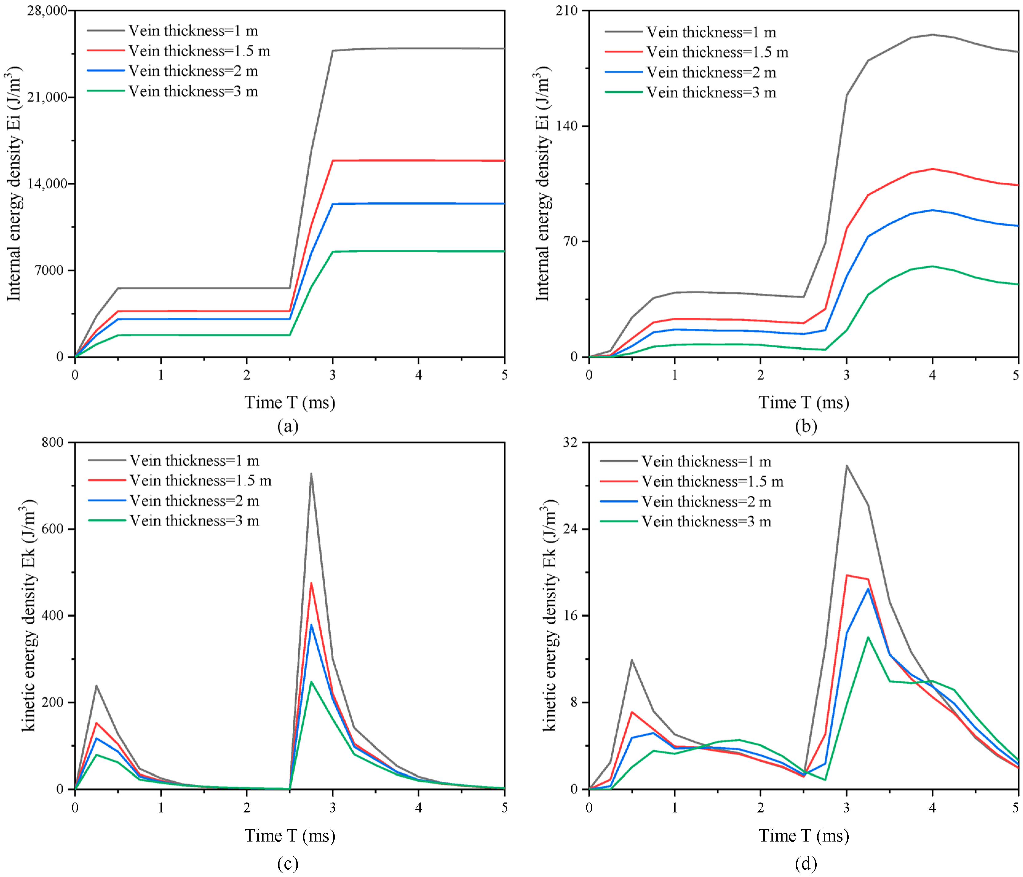
During cutting blasting in sharp, inclined, narrow vein mines, blasting energy dissipation directly governs rock fragmentation efficiency. This study analyzes the energy evolution characteristics for four vein thickness cases (i.e., 1 m, 1.5 m, 2 m and 3 m) through numerical simulation. Blasting energy dissipates primarily as kinetic energy and internal energy within the rock mass [51]. Internal energy reflects the deformation and damage accumulation within the rock mass, while kinetic energy represents the motion of rock fragments [52]. Thus, effective cutting blasting requires not only sufficient internal energy to initiate fractures, but also adequate kinetic energy to promote fragment displacement and cavity formation. To enhance the comparability of energy evolution across different vein thicknesses, energy density is defined as the energy per unit volume of rock. Figure 11 shows the evolution of internal and kinetic energy densities in both the surrounding rock and the vein under different vein thicknesses. Figure 11 demonstrates that vein thickness significantly influences the energy dissipation process. The evolution of internal and kinetic energy densities is similar in both the surrounding rock and the vein. In Figure 11a, the internal energy density rises sharply following detonation of the central cut hole (0 ms) and again after initiation of the peripheral cut holes (2.5 ms). The increase of internal energy density from the peripheral cut holes is more pronounced due to their total charge being four times greater than that of the central cut hole. Similarly, the kinetic energy density curve (Figure 11c) exhibits a corresponding bimodal characteristic, with the second peak surpassing the first. Furthermore, as vein thickness decreases from 3 m to 1 m, the peaks of both internal and kinetic energy densities show a gradual increase. This increase indicates that more blasting energy is accumulated within the rock mass under thinner vein conditions. However, the higher energy concentration does not necessarily translate into more efficient rock removal. In narrow vein environments, the surrounding rock may impose strong confinement on the vein, which limits the expansion of the blasted material. As shown in Figure 8, damage in the thin vein case is primarily concentrated along the vein–rock interface. This suggests that a considerable portion of the blasting energy may be consumed in fracturing the interface zone rather than contributing to the effective fragmentation and ejection of the vein core. Therefore, although thinner veins exhibit higher internal and kinetic energy densities in the numerical results, this should not be directly interpreted as improved cutting efficiency.
Moreover, it should also be noted that the present analysis evaluates the overall internal and kinetic energy densities within the rock mass, rather than the useful energy associated with fragments that are effectively displaced beyond the cut cavity. In practical blasting operations, the efficiency of cutting blasting is more directly related to the kinetic energy of rock fragments that are actually ejected from the cavity. Due to the limitations of the current numerical output, this quantity was not explicitly calculated in the present study. Therefore, the energy analysis presented here should be interpreted primarily as an indicator of the overall energy dissipation process rather than a direct measure of cutting efficiency.

4.3. Effect of In Situ Stress on Rock Damage Induced by Cutting Blasting in Sharp Inclined Narrow Vein Mines

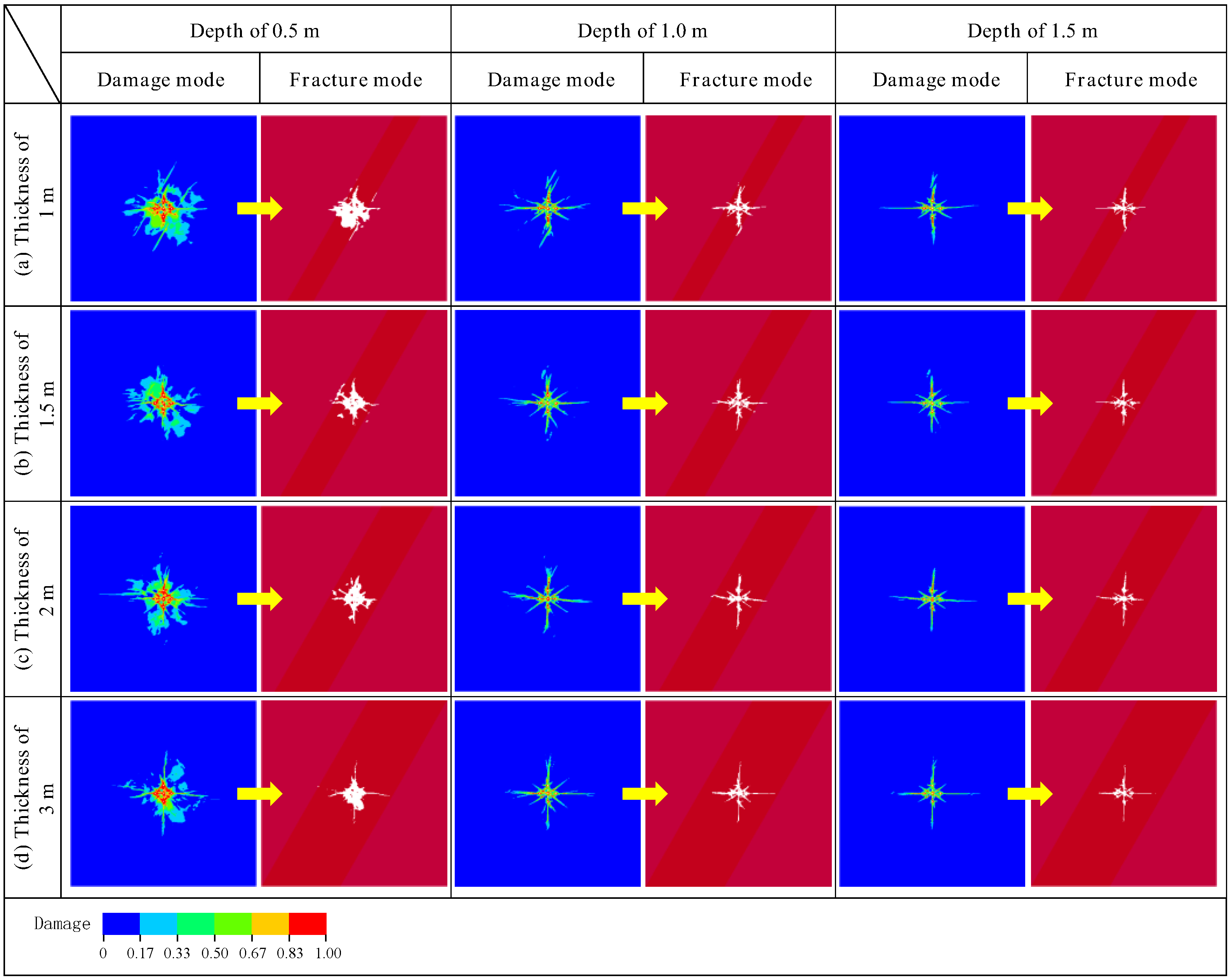
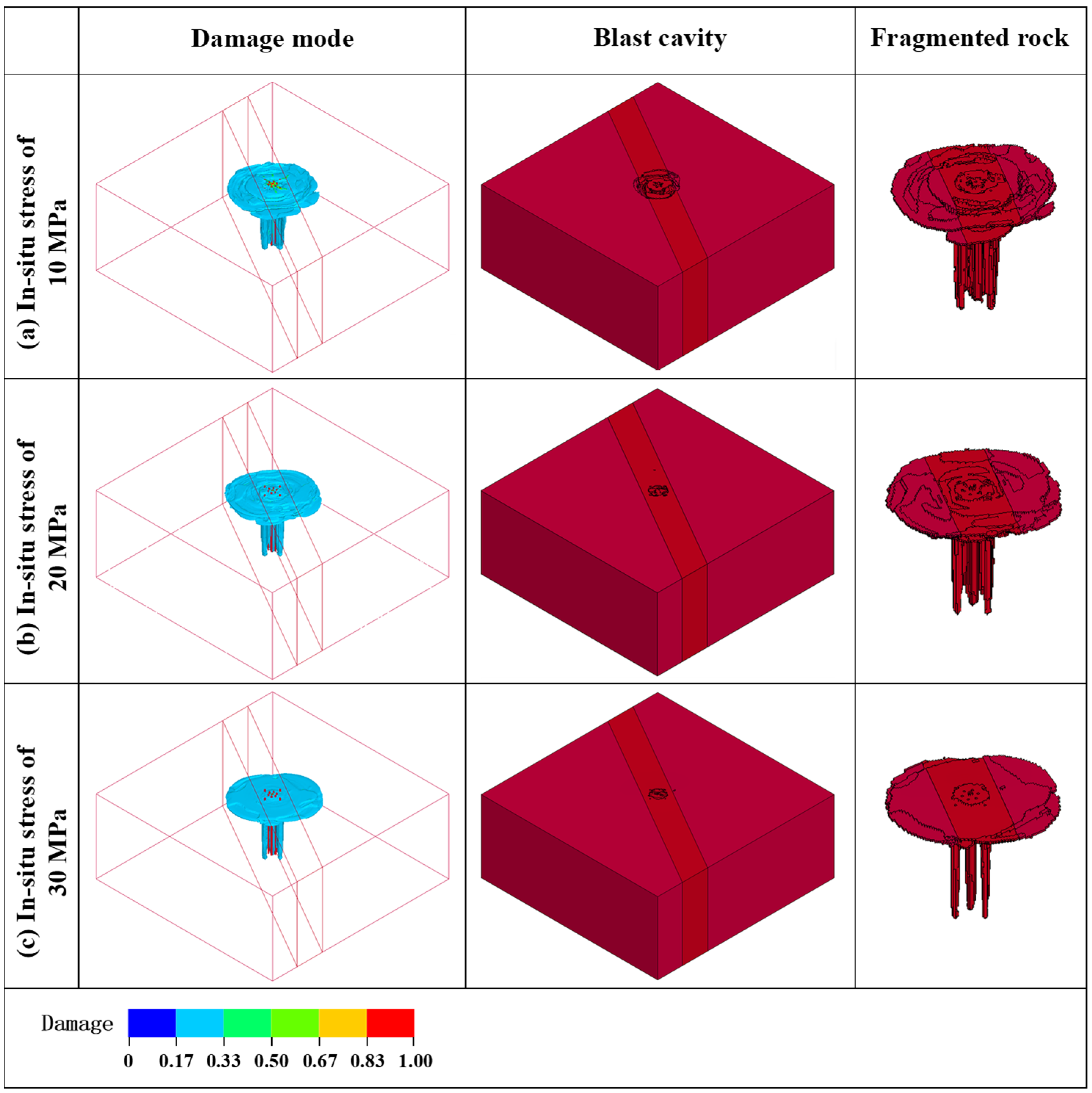
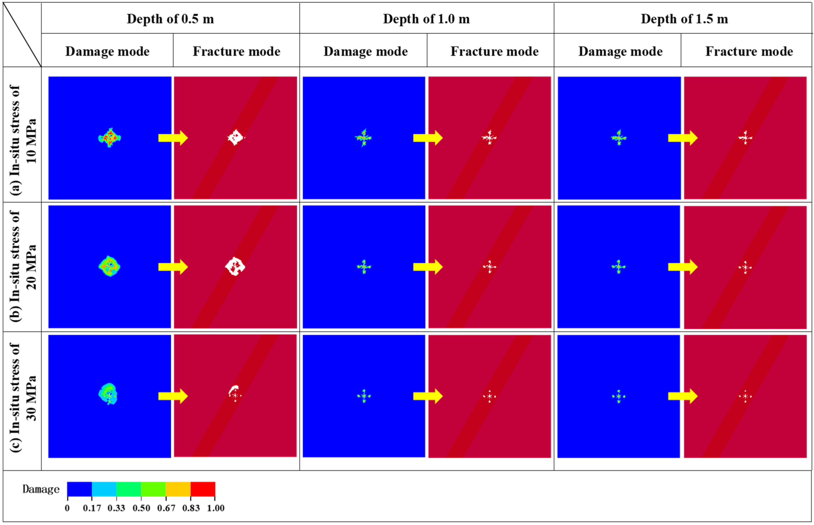
As mining progresses to greater depths, the high in situ stress has become a critical factor influencing blasting performance. In deep mining operations, the coupling between the in situ stress and blasting loading alters the damage evolution behavior of rock masses. To investigate the effect of in situ stress on cutting blasting in sharply inclined narrow vein mines, this study analyzes blast-induced damage and fracture patterns under different in situ stresses. Based on typical mining conditions, three bidirectional equal in situ stresses (i.e., 10 MPa, 20 MPa and 30 MPa) are evaluated. Figure 12 and Figure 13 present the blast-induced damage and fracture patterns under different in situ stresses. In Figure 12, as in situ stress increases from 10 MPa to 30 MPa, both the extent of rock damage and the degree of fracturing exhibit significant attenuation. Specifically, when in situ stress rises from 0 MPa to 10 MPa, radial cracks outside the blasting cavity completely disappear. With in situ stress further increased from 10 MPa to 30 MPa, visible rock fracturing at the bottom of the cavity diminishes, and the blasting cavity contour shows noticeable contraction. Figure 13 displays damage and fracture patterns at depths of 0.5 m, 1.0 m, and 1.5 m under different in situ stresses. Under 30 MPa in situ stress, adjacent blastholes fail to develop effective connecting fractures at a depth of 0.5 m, preventing complete cavity formation. Even at a depth of 1.5 m, rock fragmentation remains confined to the immediate vicinity of the blastholes.
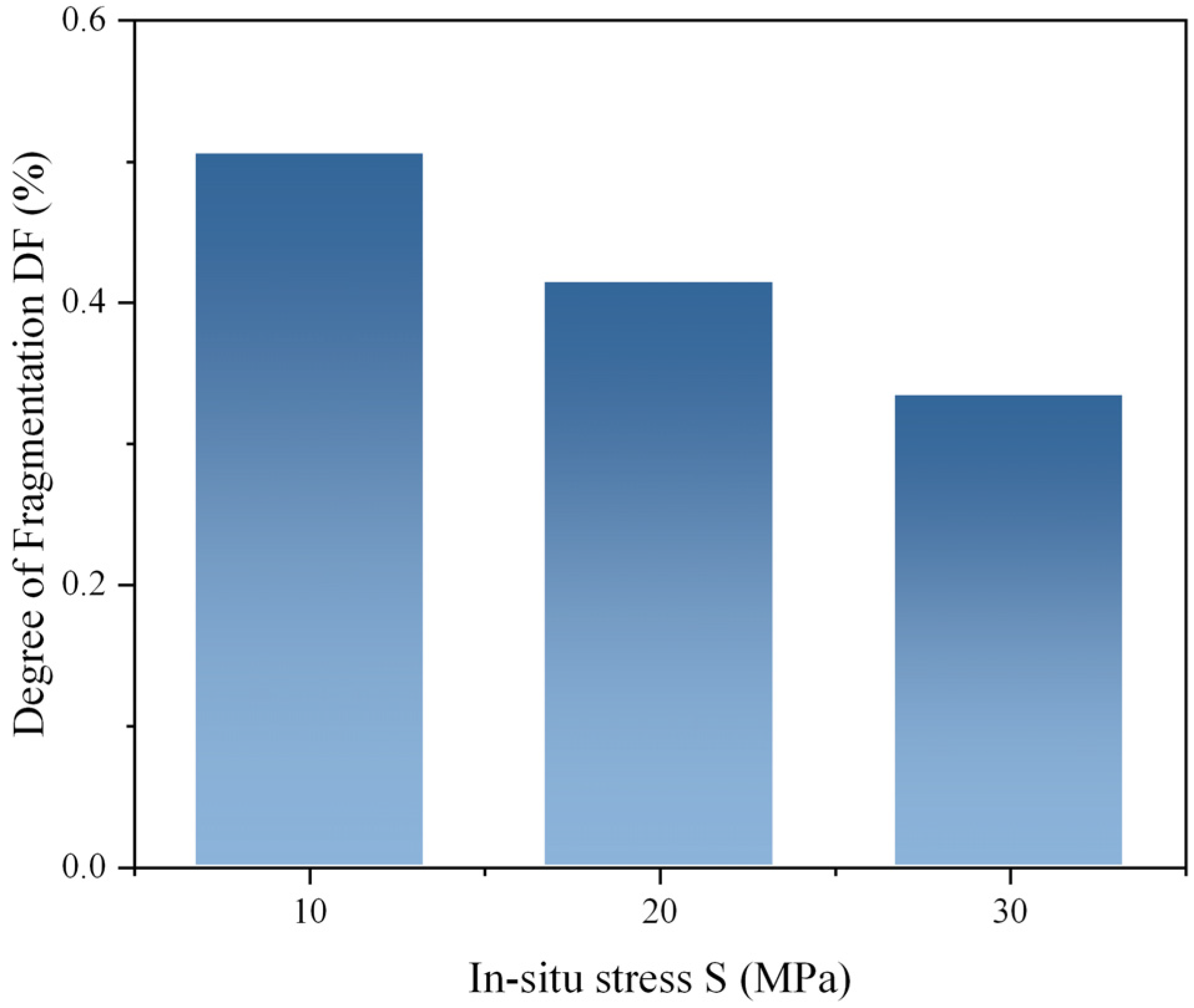
Figure 14 presents a quantitative analysis of the relationship between in situ stress and the degree of rock fragmentation under cutting blasting. The results reveal a significant negative correlation between the two parameters. Specifically, as the in situ stress increases from 10 MPa to 30 MPa, the total rock fragmentation degree decreases by 34.0%, confirming the strong inhibitory effect of high in situ stress on blasting fragmentation efficiency. On one hand, higher in situ stress intensifies the confinement acting on the rock mass, which increases its strength [29]. On the other hand, elevated confining stress fundamentally shifts the mode of rock failure from brittle fracture to ductile deformation as the confining pressure increases. In addition, the pre-existing stress field partially offsets the tensile stresses generated by blasting, thereby inhibiting the initiation and coalescence of blast-induced cracks [23].
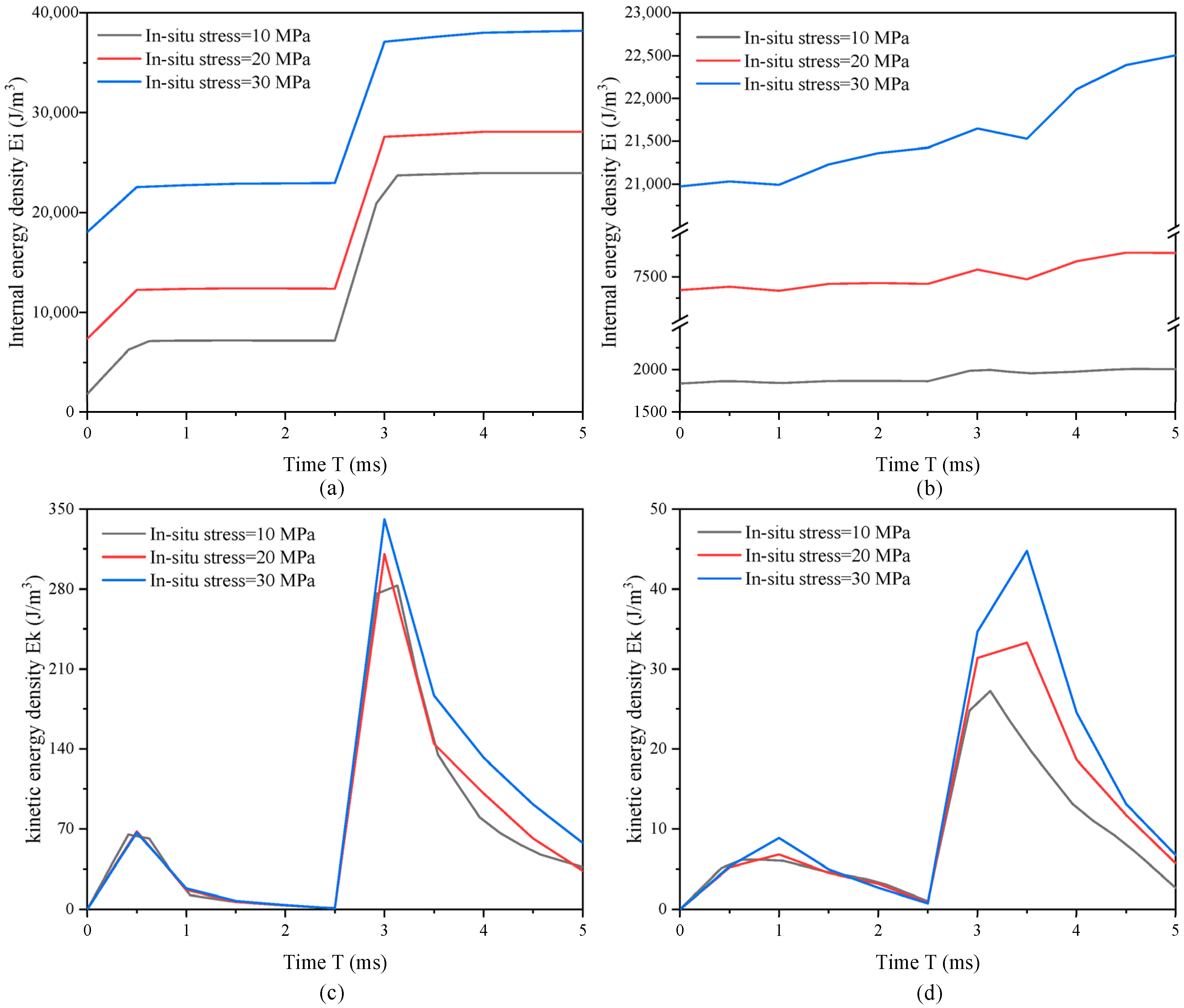
Figure 15 shows the evolution of internal and kinetic energy densities in both the surrounding rock and the vein under different in situ stresses. As the in situ stress increases, the internal energy density rises gradually in both the surrounding rock and the vein. Total internal energy comprises static internal energy from in situ stress and dynamic internal energy converted from blasting loading. In Figure 15a, the blast-induced internal energy density (i.e., the difference between the post-explosion internal energy density and the initial internal energy density) in the vein decreases at the final stage with increasing in situ stress, whereas that in the surrounding rock shows a corresponding increase. Additionally, while in situ stress exerts a limited influence on kinetic energy density from the central cut hole, it significantly affects kinetic energy generated by peripheral cut holes. The kinetic energy density produced by peripheral cut holes increases progressively with rising in situ stress.

4.4. Effect of Detonation Position on Rock Damage Induced by Cutting Blasting in Sharply Inclined Narrow Vein Mines Under 30 MPa In Situ Stress

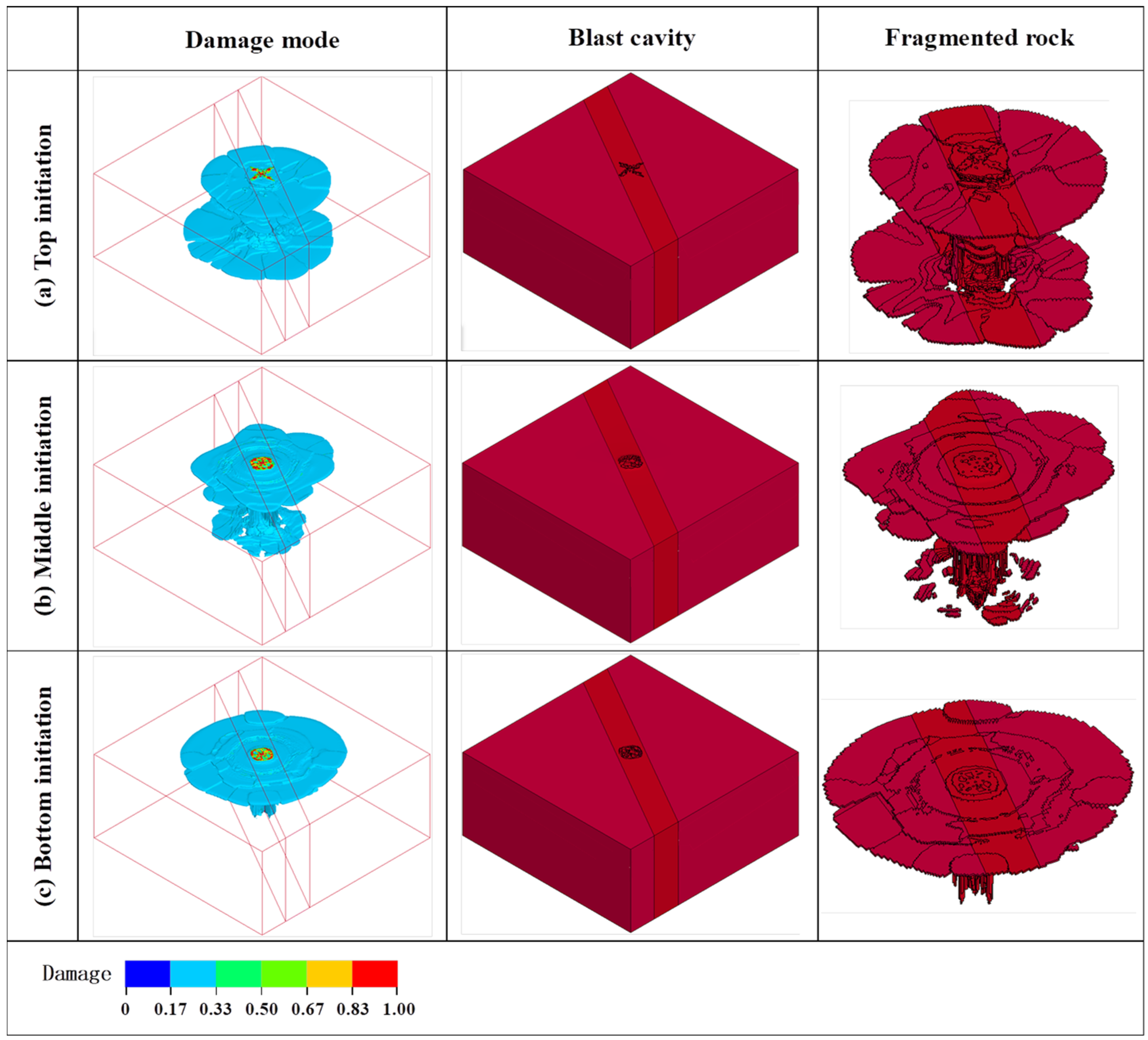
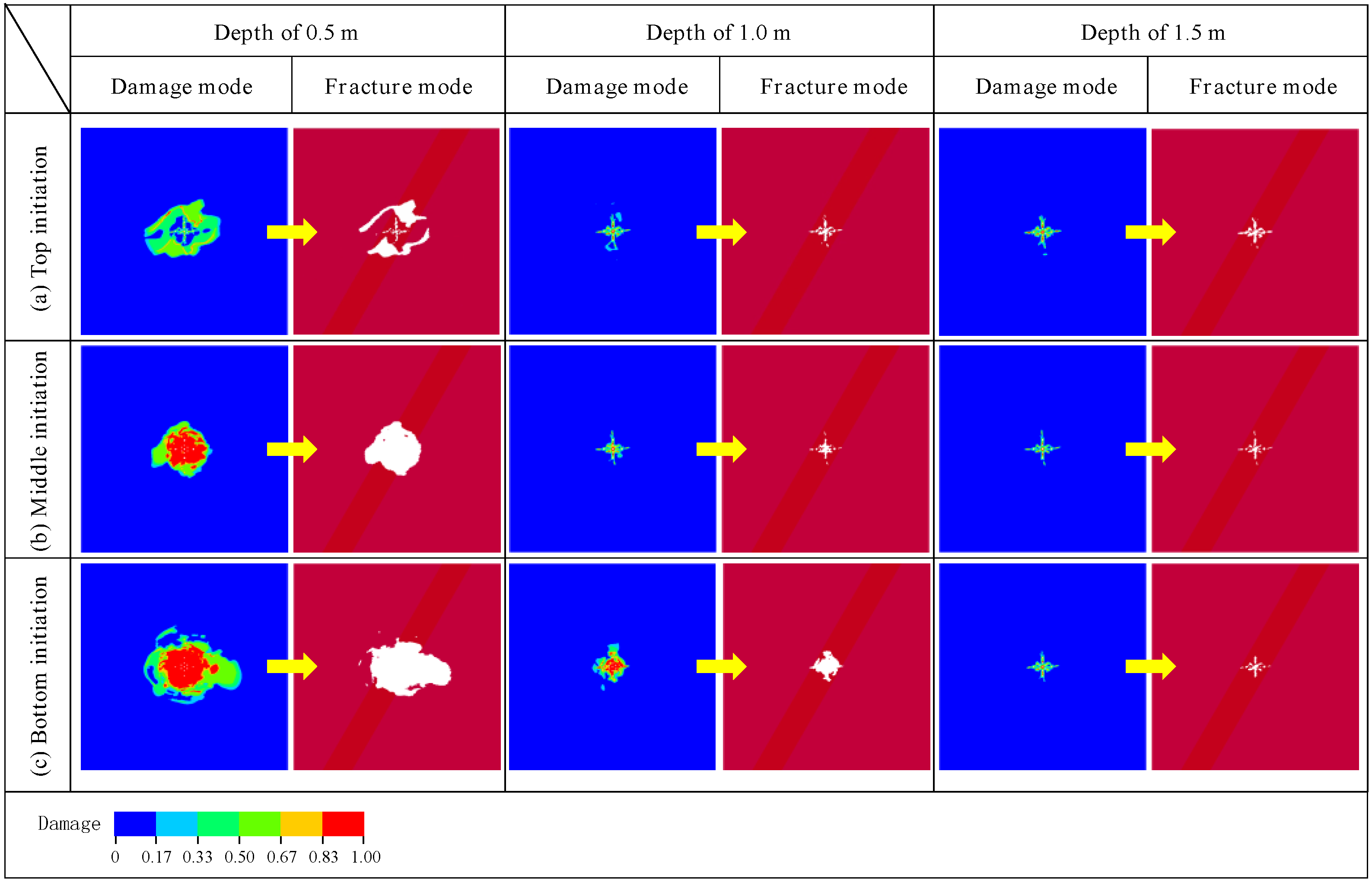
As established by the preceding analysis, cutting blasting in sharp, inclined, narrow vein mines under 30 MPa in situ stress yields suboptimal results, where the high in situ stress exacerbates rock confinement effects and hinders effective blast cavity formation. To enhance cutting blasting performance under high in situ stress, this section examines two improvement strategies: coupled charge and optimized detonation position. Specifically, coupled charge eliminates the air between explosive and borehole walls, enabling direct transmission of detonation waves to the surrounding rock mass and significantly improving explosive energy transfer efficiency. Concurrently, detonation position optimization modifies stress wave superposition patterns, offering a novel technical approach for enhancing cutting blasting effectiveness. The three-dimensional numerical model of cutting blasting with coupled charging has been developed. The model maintains an in situ stress of 30 MPa and a vein thickness of 1 m, while preserving all other geometric parameters and material constitutive relationships from the baseline configuration established in previous models. Figure 16 and Figure 17 illustrate the blast-induced damage distribution and fracture patterns under different detonation positions. The implementation of coupled charge demonstrates a remarkable expansion in rock fracture extent compared to the decoupled charge condition. This phenomenon can be attributed to the coupled charge configuration, which substantially enhances the initial shock pressure while simultaneously prolonging the duration of stress wave action. Furthermore, detonation position proves to be a decisive factor governing damage distribution and fracture propagation patterns, with different initiation schemes exhibiting distinctly differentiated fracture characteristics. Bottom initiation achieves optimal effectiveness, followed by middle initiation, while top initiation shows the most limited results. During bottom initiation, stress waves propagate from the hole bottom toward the top of the hole, facilitating highly efficient energy transmission. In contrast, the reverse propagation direction in top initiation substantially reduces energy utilization efficiency.
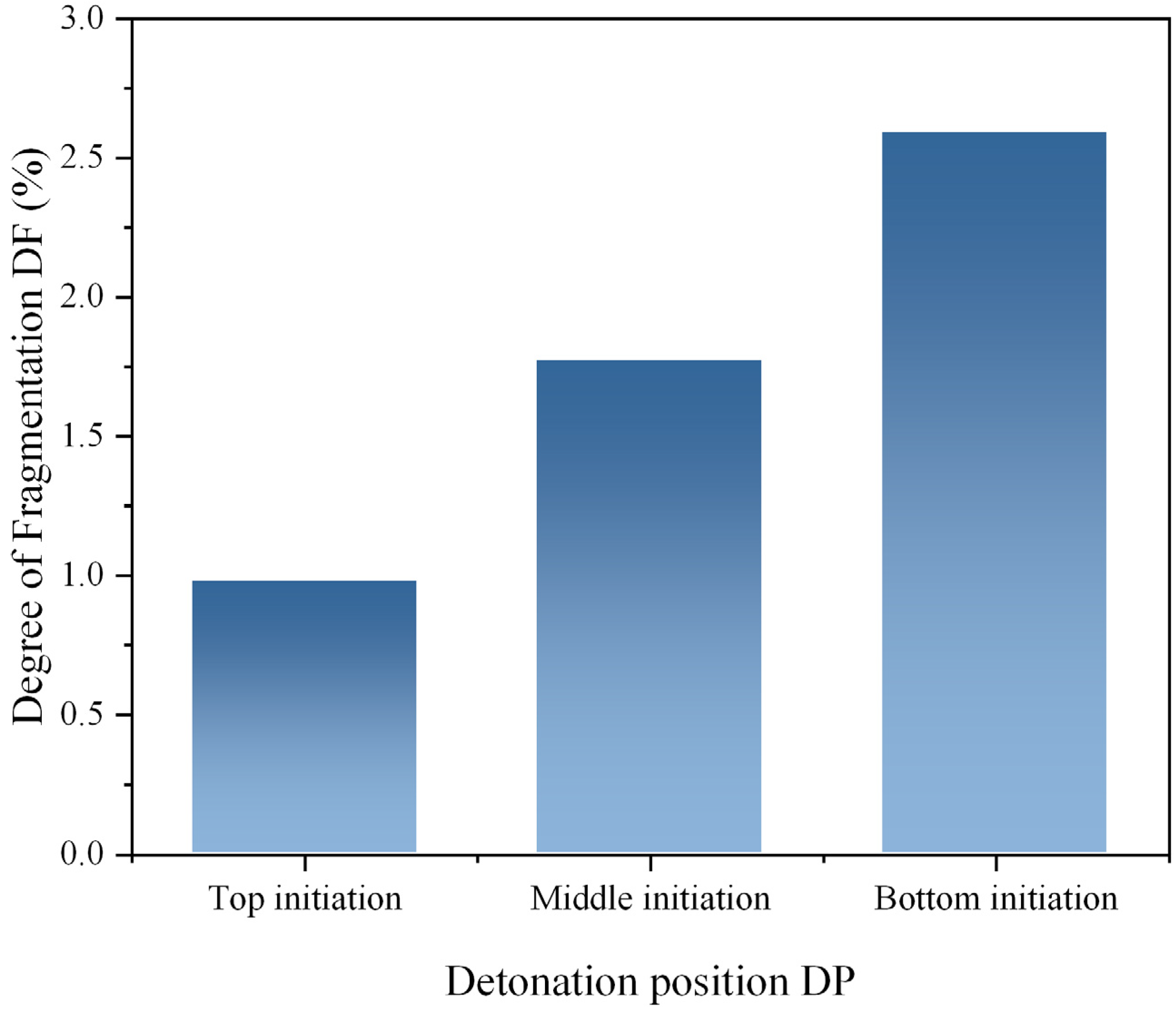
Figure 18 presents the analysis of rock fragmentation degree under different detonation positions during cutting blasting in sharp inclined narrow vein mines under 30 MPa in situ stress. Top initiation yields a fragmentation degree of 0.97%, middle initiation improves this value to 1.77%, while bottom initiation achieves the optimal index of 2.59%. The bottom initiation method achieves a remarkable 166% improvement in fragmentation degree compared to top initiation and a 46% enhancement relative to middle initiation, conclusively demonstrating its superior capability in converting explosive energy into rock fragmentation.
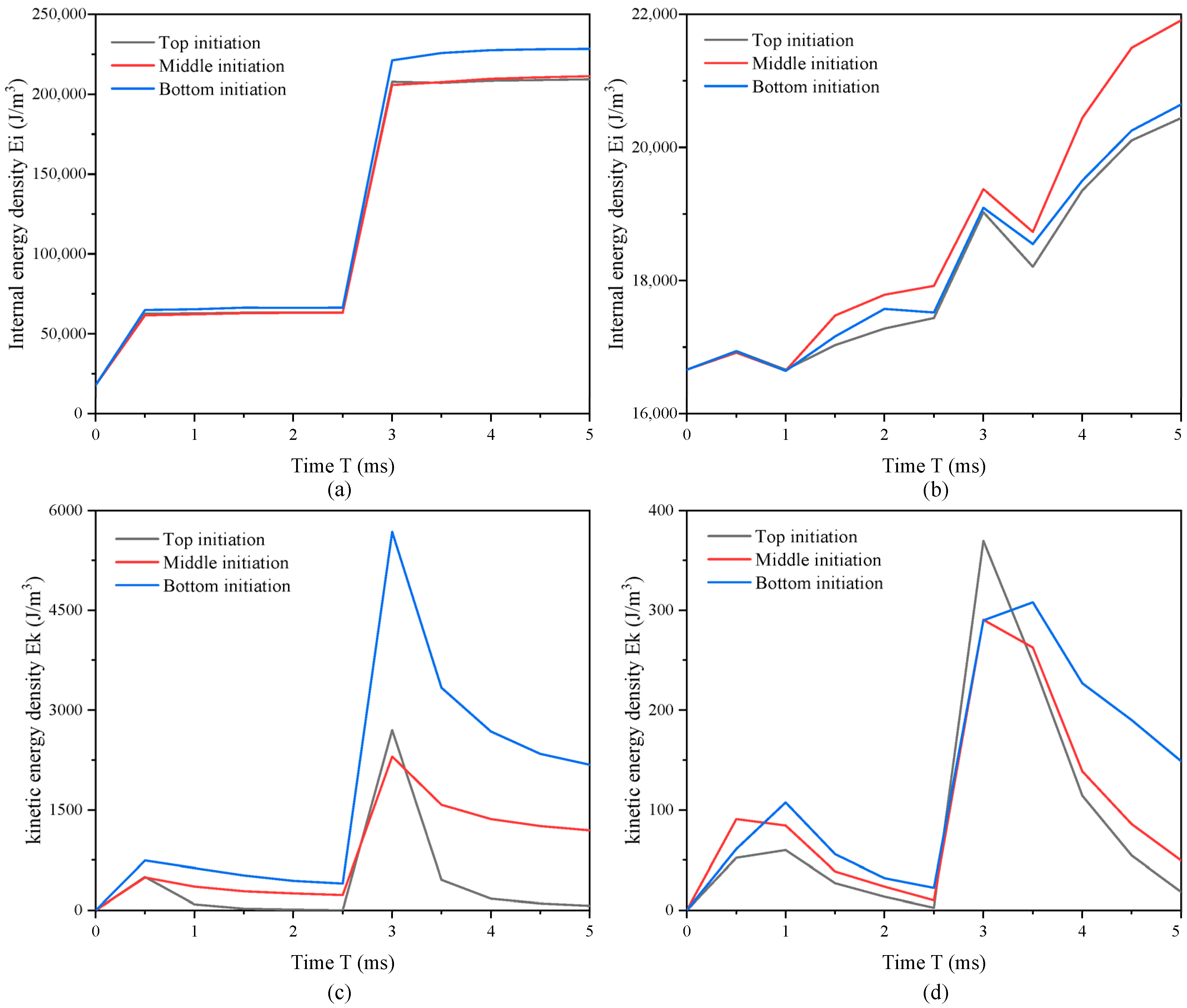
Figure 19 illustrates the evolution patterns of internal energy density and kinetic energy density in both the surrounding rock and the vein under different initiation methods. When employing the bottom initiation method, the vein attains peak values in both final internal energy density and peak kinetic energy density that substantially surpass those achieved by other initiation methods. Concurrently, the energy accumulation in the surrounding rock maintains an intermediate level under the bottom initiation method. This distinctive energy distribution pattern verifies that bottom initiation effectively concentrates explosive energy within the rock mass in a vein. In conclusion, under 30 MPa high in situ stress, the implementation of coupled charge with bottom initiation demonstrates significant enhancement in cutting blasting efficiency in this study.

5. Engineering Application

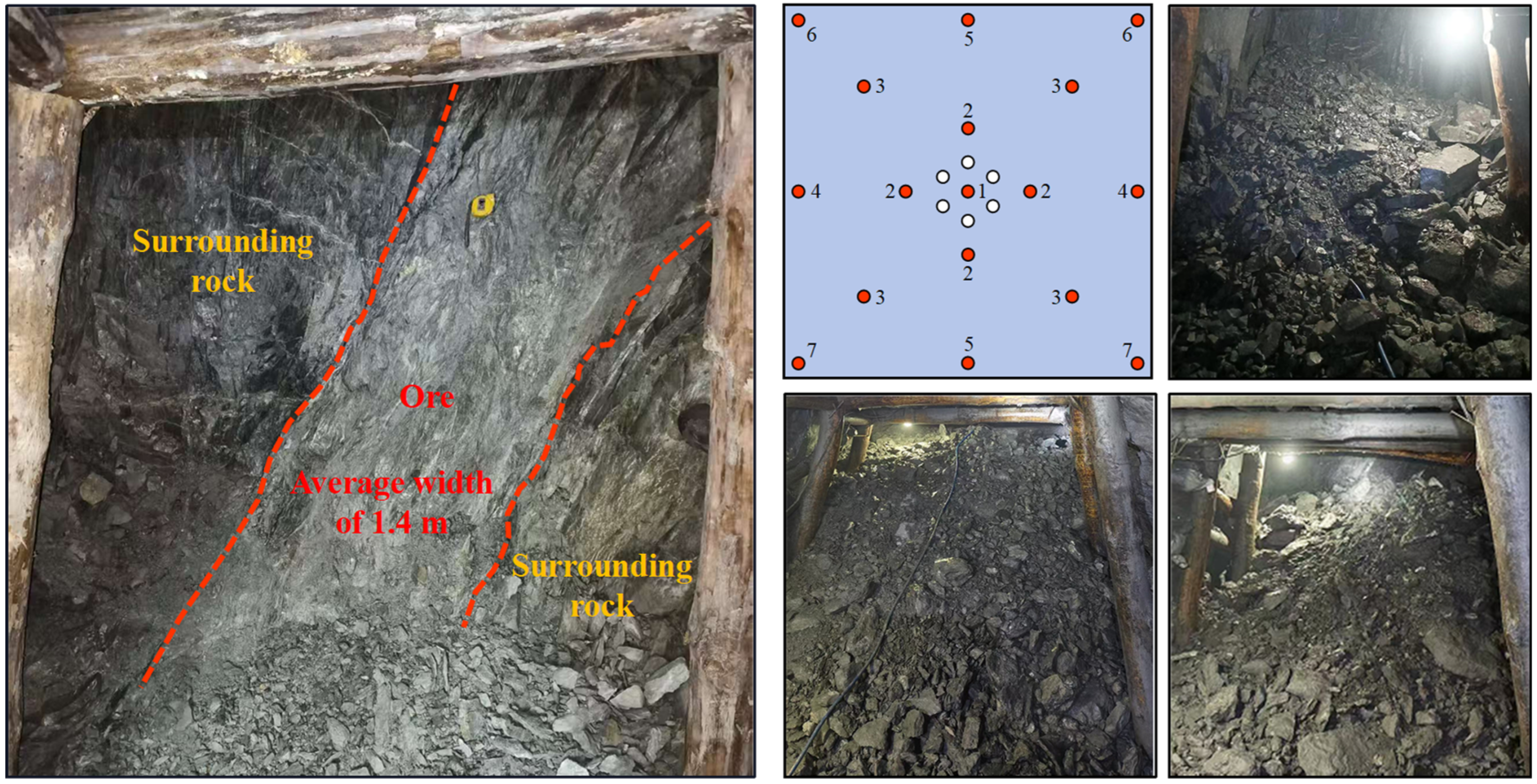
The blasting design is applied in the mining roadway at the −450 m level of Jiangdong mine. The mining roadway has a square cross-section, with the vein averaging approximately 1.4 m in width. A total of 17 charged holes and 6 empty holes are arranged, each with a depth of 2 m, as illustrated in Figure 20. The boreholes are drilled using a handheld drill rig with a 32 mm diameter bit, resulting in approximately coupled charging conditions. The cutting blasting design is implemented according to the configuration proposed in Section 3.1, involving cut holes (charged holes #1 and #2) and empty holes. Charged hole #3 is arranged as the slashing hole, holes #4, #5, and #6 serve as perimeter holes, and hole #7 functions as the bottom corner hole. The initiation sequence is designed as follows: charged hole #1 → #2 → #3 → #4 → #5 → #6 → #7, with a delay interval of 0.5 s. All charged holes are initiated from the bottom of the charges, consistent with the initiation mode analyzed in the numerical simulations. In the 1# and 2# charging holes, five pieces of emulsion explosive cartridges were placed; in the 3#, 4#, 5# and 6# charging holes, three pieces of emulsion explosive cartridges were placed; and in the 7# charging hole, four pieces of emulsion explosive cartridges were placed. Three blasting rounds were conducted under production conditions, and the representative results are presented in Figure 20. Using the new blast design with a borehole depth of 2 m, the holes were fully used, as shown by the measured advance and the remaining holes. This new design is more efficient than the original scheme with a borehole depth of 1.5 m. It should be noted that these field tests are carried out under normal production conditions rather than as strictly controlled comparative experiments. Nevertheless, the field implementation indicates that the blasting configuration derived from the numerical analysis can be practically applied in narrow vein mining roadways under high in situ stress conditions.

6. Conclusions and Limitations

6.1. Conclusions

Based on a three-dimensional numerical model calibrated through single-hole blasting test, this study employs numerical simulation to investigate the rock damage evolution and fracture development during cutting blasting in sharply inclined narrow vein mines. The research further analyzes the influence of vein width and in situ stress on damage and fracture patterns of rock mass under cutting blasting in sharp inclined narrow vein mines. The main conclusions are as follows.
(1)
Cutting blasting in sharp inclined narrow vein mines produces distinctly asymmetric damage distributions, contrasting sharply with the relatively uniform damage patterns observed in homogeneous rock masses. Four dominant fractures develop outside the blasting cavity in sharp, inclined, narrow vein mines.
(2)
Vein width significantly regulates blast-induced damage and fracture effects by controlling energy transmission. As vein thickness decreases from 3 m to 1 m, damage development outside the blasting cavity becomes increasingly oriented along the vein–rock interface. However, considering the simplified parameterization adopted for the ore rock, this finding should be interpreted primarily as a qualitative indication of the interface effect rather than a fully quantitative prediction.
(3)
The bidirectional equal in situ stress substantially inhibits damage development and fracture propagation of rock mass under cutting blasting in sharp inclined narrow vein mines. With increasing bidirectional equal in situ stress, the suppression of fracture propagation and coalescence intensifies, leading to progressive deterioration of cutting blasting performance.

6.2. Limitations

(1)
Dynamic properties of the ore rock are not independently measured in the present study. In particular, the dynamic impedance contrast between the vein and surrounding rock, which plays a key role in stress wave reflection and transmission, is not quantitatively characterized. Future work should incorporate laboratory dynamic testing methods such as Split Hopkinson Pressure Bar experiments to more accurately determine the dynamic mechanical properties of the ore rock and further validate the numerical findings.
(2)
Although the numerical model is calibrated using field blast results, the explicit representation of discontinuities is not incorporated in the parametric study. The numerical model primarily captures the influence of vein thickness and in situ stress under simplified geological conditions. Future studies should incorporate discrete fracture networks to better represent the geology of narrow veins and further improve the applicability of the results to field conditions.

Author Contributions

Conceptualization, S.W. and Z.Z.; methodology, Z.L.; software, S.W.; validation, S.W., C.H. and G.Z.; investigation, S.W.; data curation, S.W.; writing—original draft preparation, S.W.; writing—review and editing, Z.Z., Z.L., C.H., G.Z. and X.C.; visualization, S.W.; supervision, Z.Z. and Z.L.; funding acquisition, Z.Z. and X.C. All authors have read and agreed to the published version of the manuscript.

Funding

This research was funded by the National Natural Science Foundation of China, grant numbers 52334003 and 52274249; Natural Science Foundation of Hunan Province, grant number 2024JJ4064.

Institutional Review Board Statement

Not applicable.

Informed Consent Statement

Not applicable.

Data Availability Statement

The original contributions presented in this study are included in the article. Further inquiries can be directed to the corresponding author.

Conflicts of Interest

Authors Cheng He and Guihua Zeng were employed by the company Hunan Gold Tianyue Mining Co., Ltd. The remaining authors declare that the research was conducted in the absence of any commercial or financial relationships that could be construed as a potential conflict of interest.

References

  1. An, L.; Suorineni, F.T.; Xu, S.; Li, Y.-H.; Wang, Z.-C. A Feasibility Study on Confinement Effect on Blasting Performance in Narrow Vein Mining through Numerical Modelling. Int. J. Rock Mech. Min. Sci. 2018, 112, 84–94. [Google Scholar] [CrossRef] [Scilit]
  2. Zhang, S.; Shi, X.; Qiu, X.; Zong, C.; Yu, Z. Influence of Free Surface Width on Blasting Damage in Open Stope Mining in Narrow Vein Orebodies. Int. J. Rock Mech. Min. Sci. 2025, 194, 106194. [Google Scholar] [CrossRef] [Scilit]
  3. Drake, B.; Koroznikova, L.; Tuck, M.; Durkin, S. Application of Thermal Fragmentation in Australian Hard Rock Underground Narrow-Vein Mining. Min. Metall. Explor. 2020, 37, 219–229. [Google Scholar] [CrossRef] [Scilit]
  4. Cai, X.; Wang, C.; Zhou, Z.; Cheng, R.; Gao, J.; Liu, B. Dynamic Optimization of Powder Factor in Extreme-Cold Region Bench Blasting Considering Temperature Effects on Single-Hole Blasting. Rock Mech. Rock Eng. 2025, 1–26. [Google Scholar] [CrossRef] [Scilit]
  5. Li, C.; Yang, R.; Wang, Y.; Kang, Y.; Zhang, Y. Theory and Numerical Simulation of Deep Hole Cut Blasting Based on Dispersed Charge and Staged Detonation. Int. J. Rock Mech. Min. Sci. 2023, 169, 105453. [Google Scholar] [CrossRef] [Scilit]
  6. Zhang, H.; Li, T.; Du, Y.; Zhu, Q.; Zhang, X. Theoretical and Numerical Investigation of Deep-Hole Cut Blasting Based on Cavity Cutting and Fragment Throwing. Tunn. Undergr. Space Technol. 2021, 111, 103854. [Google Scholar] [CrossRef] [Scilit]
  7. Zhou, Z.; Wang, P.; Cheng, R.; Cai, X.; Chen, C. Blast-Induced Damage and Fracture of Rock Mass in Cutting Blasting with a Large Empty Hole under High in-Situ Stress. Tunn. Undergr. Space Technol. 2025, 166, 106942. [Google Scholar] [CrossRef] [Scilit]
  8. Li, C.; Yang, R.; Wang, Y.; Kang, Y.; Zhang, Y.; Xie, P. Theoretical and Numerical Simulation Investigation of Deep Hole Dispersed Charge Cut Blasting. Int. J. Coal Sci. Technol. 2023, 10, 15. [Google Scholar] [CrossRef] [Scilit]
  9. Xie, L.X.; Lu, W.B.; Zhang, Q.B.; Jiang, Q.H.; Chen, M.; Zhao, J. Analysis of Damage Mechanisms and Optimization of Cut Blasting Design under High In-Situ Stresses. Tunn. Undergr. Space Technol. 2017, 66, 19–33. [Google Scholar] [CrossRef] [Scilit]
  10. Li, C.; Yang, R.; Zuo, J.; Xie, P. Theory and Field Tests of Innovative Cut Blasting Method for Rock Roadway Excavation. Tunn. Undergr. Space Technol. 2025, 155, 106180. [Google Scholar] [CrossRef] [Scilit]
  11. Wang, P.; Zhou, Z.; Liu, Y.; Cai, X.; Chen, C. Investigation of Rock Fracturing During Cut Blasting with a Large Empty Hole Under Non-Hydrostatic Confining Stress: Insights for Optimizing Blast Parameters. Rock Mech. Rock Eng. 2026. [Google Scholar] [CrossRef] [Scilit]
  12. Hefni, M.A.; Abdellah, W.R.E.; Ahmed, H.M. Factors Influencing Stope Hanging Wall Stability and Ore Dilution in Narrow-Vein Deposits: Part II. Geotech. Geol. Eng. 2020, 38, 3795–3813. [Google Scholar] [CrossRef] [Scilit]
  13. Vishwakarma, A.K.; Himanshu, V.K.; Dey, K. Evaluation of Optimum Burden for the Excavation of Narrow Vein Ore Deposits Using Numerical Simulation. Rock Mech. Rock Eng. 2024, 57, 945–960. [Google Scholar] [CrossRef] [Scilit]
  14. Li, J.; Liu, S.; Ren, W.; Liu, H.; Li, S.; Yan, K.; Li, J.; Liu, S.; Ren, W.; Liu, H.; et al. Research on Engineering Practice and Effect Evaluation Method of Pressure Relief in Deep Rock Burst Danger Area of Coal Mine. Minerals 2023, 13, 570. [Google Scholar] [CrossRef] [Scilit]
  15. Zhou, Z.; Wang, P.; Cai, X.; Cao, W. Influence of Water Content on Energy Partition and Release in Rock Failure: Implications for Water-Weakening on Rock-Burst Proneness. Rock Mech. Rock Eng. 2023, 56, 6189–6205. [Google Scholar] [CrossRef] [Scilit]
  16. Zhang, H.; Li, T.; Gao, X.; Zhu, Q.; Zhang, S.; Ran, J. Numerical Study on Evolution Mechanism of Cut Blasting and Cavity Formation Under Confining Pressure. Rock Mech. Rock Eng. 2023, 56, 8571–8590. [Google Scholar] [CrossRef] [Scilit]
  17. Zhao, X.; Zhou, X.; Zhao, X.; Zhou, X. Design Method and Application of Stope Structure Parameters in Deep Metal Mines Based on an Improved Stability Graph. Minerals 2022, 13, 2. [Google Scholar] [CrossRef] [Scilit]
  18. Cai, X.; Wang, P.; Zhou, Z.; Wang, Y.; Zhang, J. Dynamic Mechanical Response and Multiscale Fracturing of Pre-Stressed Rock: Implications for Pillar Burst Mechanism and Prevention. Tunn. Undergr. Space Technol. 2026, 168, 107116. [Google Scholar] [CrossRef] [Scilit]
  19. Yan, G.; Zhang, F.; Ku, T.; Hao, Q.; Peng, J. Experimental Study and Mechanism Analysis on the Effects of Biaxial In-Situ Stress on Hard Rock Blasting. Rock Mech. Rock Eng. 2023, 56, 3709–3723. [Google Scholar] [CrossRef] [Scilit]
  20. Ding, J.; Yang, J.; Ye, Z.; Leng, Z.; Zhou, C. Numerical Study on Rock Blasting Assisted by In-Situ Stress Redistribution. Tunn. Undergr. Space Technol. 2024, 153, 106022. [Google Scholar] [CrossRef] [Scilit]
  21. Li, Q.; Li, H.; He, L.; Li, X. Effect of Empty-Hole on the Rock Blasting under in-Situ Stress. Comput. Geotech. 2025, 185, 107290. [Google Scholar] [CrossRef] [Scilit]
  22. Tu, M.; Zhao, G.; Zhang, X.; Bu, Q.; Dang, J. Fracture Evolution between Blasting Roof Cutting Holes in a Mining Stress Environment. Minerals 2022, 12, 418. [Google Scholar] [CrossRef] [Scilit]
  23. Wang, H.; Wang, Z.; Wang, J.; Wang, S.; Wang, H.; Yin, Y.; Li, F. Effect of Confining Pressure on Damage Accumulation of Rock under Repeated Blast Loading. Int. J. Impact Eng. 2021, 156, 103961. [Google Scholar] [CrossRef] [Scilit]
  24. Zhang, F.; Yan, G.; Peng, J.; Qiu, Z.; Dai, X. Experimental Study on Crack Formation in Sandstone during Crater Blasting under High Geological Stress. Bull. Eng. Geol. Environ. 2020, 79, 1323–1332. [Google Scholar] [CrossRef] [Scilit]
  25. Liu, K.; Li, X.; Huang, L.; Sha, Y.; Yang, J.; Zhao, X.; Ma, S.; Hong, Z. Investigation on Rock Fracturing in Presplit Blasting Under Various Initial Stresses. Rock Mech. Rock Eng. 2024, 57, 6927–6950. [Google Scholar] [CrossRef] [Scilit]
  26. Li, X.; Liu, K.; Sha, Y.; Yang, J.; Ma, S.; Hong, Z. Investigation on Radial Fracturing around Borehole under Combined Static Stress and Blasting. Theor. Appl. Fract. Mech. 2023, 127, 104038. [Google Scholar] [CrossRef] [Scilit]
  27. Li, X.; Liu, K.; Yang, J.; Qiu, T.; Sha, Y. Effects of In-Situ Stress on Rock Cracking in Presplit Blasting. Comput. Geotech. 2024, 168, 106124. [Google Scholar] [CrossRef] [Scilit]
  28. Wu, Y.; Zhang, X.; Li, Z.; Gao, W.; Xu, Z.; Zhang, Y.; Zhou, J. Effects of In-Situ Stress on Damage and Fractal during Cutting Blasting Excavation. Fractal Fract. 2024, 8, 450. [Google Scholar] [CrossRef] [Scilit]
  29. Li, X.; Liu, K.; Yang, J.; Song, R. Numerical Study on Blast-Induced Fragmentation in Deep Rock Mass. Int. J. Impact Eng. 2022, 170, 104367. [Google Scholar] [CrossRef] [Scilit]
  30. Hong, Z.; Tao, M.; Cui, X.; Wu, C.; Zhao, M. Experimental and Numerical Studies of the Blast-Induced Overbreak and Underbreak in Underground Roadways. Undergr. Space 2023, 8, 61–79. [Google Scholar] [CrossRef] [Scilit]
  31. Rossmanith, H.P.; Knasmillner, R.E.; Daehnke, A.; Mishnaevsky, L. Wave Propagation, Damage Evolution, and Dynamic Fracture Extension. Part II. Blasting. Mater. Sci. 1996, 32, 403–410. [Google Scholar] [CrossRef] [Scilit]
  32. Yang, L.; Ding, C. Fracture Mechanism Due to Blast-Imposed Loading under High Static Stress Conditions. Int. J. Rock Mech. Min. Sci. 2018, 107, 150–158. [Google Scholar] [CrossRef] [Scilit]
  33. Yang, L.; Yang, A.; Chen, S.; Fang, S.; Huang, C.; Xie, H. Model Experimental Study on the Effects of in Situ Stresses on Pre-Splitting Blasting Damage and Strain Development. Int. J. Rock Mech. Min. Sci. 2021, 138, 104587. [Google Scholar] [CrossRef] [Scilit]
  34. Yi, C.; Johansson, D.; Greberg, J. Effects of In-Situ Stresses on the Fracturing of Rock by Blasting. Comput. Geotech. 2018, 104, 321–330. [Google Scholar] [CrossRef] [Scilit]
  35. Liu, H.; Huang, L.; Wang, Z.; Wu, Y.; Li, X. Experimental Study on Dynamic Response of Hard Rock Blasting under In-Situ Stress. Int. J. Rock Mech. Min. Sci. 2024, 182, 105860. [Google Scholar] [CrossRef] [Scilit]
  36. Liu, H.; Huang, L.; Chen, J.; Wang, Z.; Wu, Y.; Li, M.; Li, X. Research on Fracturing Behavior and Mechanism of Multi-Empty-Hole Directional Blasting in Deep Hard Rock. Tunn. Undergr. Space Technol. 2025, 165, 106925. [Google Scholar] [CrossRef] [Scilit]
  37. Pan, R.; Wang, P.; Zhou, Z.; Lan, R.; Chen, L.; Yang, H.; Chen, C.; Zhang, J.; Liu, Y.; Ma, J. Effects of Confining Stress on Blast-Induced Damage Distribution of Rock with Discontinuity. Sustainability 2023, 15, 13278. [Google Scholar] [CrossRef] [Scilit]
  38. Li, X.; Chen, J.; Ma, C.; Huang, L.; Li, C.; Zhang, J.; Zhao, Y. A Novel In-Situ Stress Measurement Method Incorporating Non-Oriented Core Ground Re-Orientation and Acoustic Emission: A Case Study of a Deep Borehole. Int. J. Rock Mech. Min. Sci. 2022, 152, 105079. [Google Scholar] [CrossRef] [Scilit]
  39. Qiu, X.; Shi, X.; Gou, Y.; Zhou, J.; Chen, H.; Huo, X. Short-Delay Blasting with Single Free Surface: Results of Experimental Tests. Tunn. Undergr. Space Technol. 2018, 74, 119–130. [Google Scholar] [CrossRef] [Scilit]
  40. Livermore Software Technology Corporation. LS-DYNA® Keyword User’s Manual; Volume II Material Models, LS-DYNA R7.1, May 19, 2014 (Revision: 5442); Livermore Software Technology Corporation: Livermore, CA, USA, 2014. [Google Scholar]
  41. Liu, K.; Yang, J.; Li, X.; Hao, H.; Li, Q.; Liu, Z.; Wang, C. Study on the Long-Hole Raising Technique Using One Blast Based on Vertical Crater Retreat Multiple Deck Shots. Int. J. Rock Mech. Min. Sci. 2018, 109, 52–67. [Google Scholar] [CrossRef] [Scilit]
  42. Wang, Z.; Wang, H.; Wang, J.; Tian, N. Finite Element Analyses of Constitutive Models Performance in the Simulation of Blast-Induced Rock Cracks. Comput. Geotech. 2021, 135, 104172. [Google Scholar] [CrossRef] [Scilit]
  43. Yang, X.; Wang, C.; Chu, H.; Yan, S.; Wei, H.; Yu, M. Study on the Stress Field and Crack Propagation of Coal Mass Induced by High-Pressure Air Blasting. Minerals 2022, 12, 300. [Google Scholar] [CrossRef] [Scilit]
  44. Duc-Kien, T.; Duy-Liem, N.; Duy-Duan, N. A Calibration of the Material Model for FRC. Constr. Build. Mater. 2020, 254, 119293. [Google Scholar] [CrossRef] [Scilit]
  45. Li, X.; Zhu, Z.; Wang, M.; Wan, D.; Zhou, L.; Liu, R. Numerical Study on the Behavior of Blasting in Deep Rock Masses. Tunn. Undergr. Space Technol. 2021, 113, 103968. [Google Scholar] [CrossRef] [Scilit]
  46. Li, X.; Liu, K.; Sha, Y.; Yang, J.; Hong, Z. Numerical Investigation on Blast-Induced Rock Fragmentation with Different Stemming Structures. Geomech. Geophys. Geo-Energy Geo-Resour. 2023, 9, 112. [Google Scholar] [CrossRef] [Scilit]
  47. Yang, J.H.; Lu, W.B.; Jiang, Q.H.; Yao, C.; Zhou, C.B. Frequency Comparison of Blast-Induced Vibration per Delay for the Full-Face Millisecond Delay Blasting in Underground Opening Excavation. Tunn. Undergr. Space Technol. 2016, 51, 189–201. [Google Scholar] [CrossRef] [Scilit]
  48. Liu, K.; Li, X.; Yang, J.; Zhou, Z.; Sha, Y.; Hong, Z. Experimental and Numerical Investigation on Rock Fracturing and Fragmentation under Coupled Static Pressure and Blasting. Eng. Fract. Mech. 2024, 311, 110593. [Google Scholar] [CrossRef] [Scilit]
  49. Xiao, C.; Yang, R.; Ma, X.; Wang, Y.; Ding, C. Damage Evaluation of Rock Blasting Based on Multi-Fractal Study. Int. J. Impact Eng. 2024, 188, 104953. [Google Scholar] [CrossRef] [Scilit]
  50. Lei, M.; He, R.; Liu, L.; Sun, N.; Qin, G.; Zhang, Y. Mechanical Mechanism and Shaping Effect of Tunnel Blasting Construction in Rock with Weak Interlayer. Sustainability 2022, 14, 13278. [Google Scholar] [CrossRef] [Scilit]
  51. Hong, Z.; Tao, M.; Zhao, R.; Zhou, J.; Zhao, M. Investigation on Overbreak and Underbreak of Pre-Stressed Tunnels under the Impact of Decoupled Charge Blasting. Int. J. Impact Eng. 2023, 182, 104784. [Google Scholar] [CrossRef] [Scilit]
  52. Zhao, J.; Li, D.; Ranjith, P.G.; Su, X.; Li, Y.; Lyu, X. Innovative Cut Blasting Method for Rock Excavation at Depth Based on Numerical Simulation and Field Tests. Tunn. Undergr. Space Technol. 2025, 155, 106211. [Google Scholar] [CrossRef] [Scilit]
Figure 1. Test configuration and blasting results.
Applsci 16 02980 g001
Figure 2. Geometric parameters and numerical model: (a) geometric model and (b) numerical model.
Applsci 16 02980 g002
Figure 3. Comparison between the blasting cavity profile obtained in the test and the simulated damage profile.
Applsci 16 02980 g003
Figure 4. Evolution of damage during cutting blasting in homogeneous rock.
Applsci 16 02980 g004
Figure 5. Evolution of damage during cutting blasting in sharp inclined narrow vein mines.
Applsci 16 02980 g005
Figure 6. Rock fracture patterns under cutting blasting: (a) homogeneous rock and (b) sharply inclined narrow vein mines.
Applsci 16 02980 g006
Figure 7. Rock fragmentation degree under cutting blasting in the homogeneous rock and sharp inclined narrow vein mines.
Applsci 16 02980 g007
Figure 8. Rock damage and fracture patterns under cutting blasting under vein thickness of (a) 1 m, (b) 1.5 m, (c) 2 m and (d) 3 m.
Applsci 16 02980 g008
Figure 9. Rock damage and fracture patterns under cutting blasting at different positions under vein thickness of (a) 1 m, (b) 1.5 m, (c) 2 m and (d) 3 m.
Applsci 16 02980 g009
Figure 10. Rock fragmentation degree under cutting blasting under different vein thicknesses.
Applsci 16 02980 g010
Figure 11. Evolution of energy densities under cutting blasting under different vein thicknesses: (a) internal energy density of vein, (b) internal energy density of surrounding rock, (c) kinetic energy density of vein and (d) kinetic energy density of surrounding rock.
Applsci 16 02980 g011
Figure 12. Rock damage and fracture patterns under cutting blasting under in situ stress of (a) 10 MPa, (b) 20 MPa and (c) 30 MPa.
Applsci 16 02980 g012
Figure 13. Rock damage and fracture patterns under cutting blasting at different positions under in situ stress of (a) 10 MPa, (b) 20 MPa and (c) 30 MPa.
Applsci 16 02980 g013
Figure 14. Rock fragmentation degree under cutting blasting under different in situ stresses.
Applsci 16 02980 g014
Figure 15. Evolution of energy densities under cutting blasting under different in situ stresses: (a) internal energy density of vein, (b) internal energy density of surrounding rock, (c) kinetic energy density of vein and (d) kinetic energy density of surrounding rock.
Applsci 16 02980 g015
Figure 16. Rock damage and fracture patterns under cutting blasting under (a) top initiation, (b) middle initiation and (c) bottom initiation.
Applsci 16 02980 g016
Figure 17. Rock damage and fracture patterns under cutting blasting at different positions under (a) top initiation, (b) middle initiation and (c) bottom initiation.
Applsci 16 02980 g017
Figure 18. Rock fragmentation degree under cutting blasting under different detonation positions.
Applsci 16 02980 g018
Figure 19. Evolution of energy densities under cutting blasting under different detonation positions: (a) internal energy density of vein, (b) internal energy density of surrounding rock, (c) kinetic energy density of vein and (d) kinetic energy density of surrounding rock.
Applsci 16 02980 g019
Figure 20. Field application and blasting results (Numbers 1 to 7 represent the detonation sequence. Red dots represent the charging holes, and white dots represent the empty holes.).
Applsci 16 02980 g020
Table 1. The RHT parameters of rock.
ParameterSurrounding RockOre Rock
Compressive strength fc (MPa)77.5635.68
Elastic shear modulus G (GPa)12.955.96
Crush pressure Pcrush (MPa)51.7123.79
Hugoniot polynomial coefficient A1 (GPa)40.4222.18
Hugoniot polynomial coefficient A2 (GPa)49.2127.06
Hugoniot polynomial coefficient A3 (GPa)10.365.68
Parameter for polynomial EOS T1 (GPa)40.4222.18
Compressive strain rate dependence exponent βc0.0160.031
Tensile strain rate dependence exponent βt0.0210.036
Table 2. The common parameters of RHT model.
ParameterValueParameterValue
Mass density ρ (kg·m−3)2552Break compressive strain rate Ec3 × 1025
Reference tensile strain rate Rt3 × 10−6Break tensile strain rate Et3 × 1025
Parameter for polynomial EOS T2 (GPa)0Lode angle dependence factor Q00.68
Relative tensile strength ft0.05Lode angle dependence factor B0.01
Relative shear strength fs0.16Compressive yield surface parameter Gc0.53
Parameter for polynomial EOS B01.22Tensile yield surface parameter Gt0.70
Parameter for polynomial EOS B11.22Compaction pressure Pco (GPa)6
Residual surface parameter AF1.60Residual surface parameter NF0.61
Damage parameter D10.04Shear modulus reduction factor Xi0.5
Damage parameter D21.0Eroding plastic strain Epsf2.0
Gruneisen gamma γ0Minimum damaged residual strain Epm0.008
Failure surface parameter A2.61Porosity exponent Np3.0
Failure surface parameter N0.68Initial porosity α1.0
Pressure influence on plastic flow in tension Ptf0.001Reference compressive strain rate Rc3 × 10−5
Disclaimer/Publisher’s Note: The statements, opinions and data contained in all publications are solely those of the individual author(s) and contributor(s) and not of MDPI and/or the editor(s). MDPI and/or the editor(s) disclaim responsibility for any injury to people or property resulting from any ideas, methods, instructions or products referred to in the content.