Article

Study on the Influence of Lateral Stress on Shear Strength of Hard Rock Using the True Triaxial Multistage Direct Shear Test

1
PowerChina Huadong Engineering Corporation Limited, Hangzhou 310000, China
2
School of Mining Engineering, North China University of Science and Technology, Tangshan 063000, China
3
State Key Laboratory of Intelligent Deep Metal Mining and Equipment, Northeastern University, Shenyang 110000, China
*
Author to whom correspondence should be addressed.
Appl. Sci. 2026, 16(5), 2288; https://doi.org/10.3390/app16052288
Submission received: 6 January 2026 / Revised: 9 February 2026 / Accepted: 11 February 2026 / Published: 27 February 2026
(This article belongs to the Special Issue Reservoir Stimulation in Deep Geothermal Reservoir)

Abstract

The shear strength of rock discontinuities is critical for the stability of deep underground projects. However, its accurate determination is hindered by the discreteness of natural joints and the limitations of conventional direct shear tests, which operate under simplified two-dimensional stress conditions, unlike the true triaxial (σ1 > σ2 > σ3) in situ state. This study introduces and validates a multistage true triaxial direct shear testing method as a practical solution. Through controlled pre-peak unloading, complete failure envelopes were successfully obtained from single specimens of jointed granite and intact marble with minimal strength degradation. The results demonstrate that lateral stress significantly enhances the peak shear strength, characterized by a marked increase in cohesion coupled with a slight decrease in the internal friction angle. For intact marble, increasing the lateral stress from 0 to 20 MPa raised the cohesion by approximately 67% (from 34.9 to 58.4 MPa), while the friction angle decreased from 49.3° to 42.8°. For jointed granite, cohesion showed a more variable but consistently strengthening trend with confinement, accompanied by a minor adjustment in the friction angle. Acoustic emission monitoring confirms that pre-peak unloading confines damage accumulation to microcrack reactivation. From a fracture mechanics perspective, the strength enhancement is attributed to the suppression of tensile crack propagation and the promotion of shear localization under three-dimensional confinement. Collectively, this work establishes a novel experimental framework and elucidates the mechanism by which lateral stress governs the shear behavior of hard rock, offering direct implications for the design and stability assessment of deep excavations and related geo-engineering projects.

1. Introduction

The development of deep underground engineering has exposed rock masses to increasingly complex geological environments and extreme stress conditions [1,2]. These scenarios range from deep tunneling and mining to emerging fields like enhanced geothermal system (EGS) development in hot dry rock, where rock masses are subjected to a conjunction of high stresses, thermal loading, and hydraulic stimulation. Under high geo-stress conditions, disasters such as rockbursts, collapses, and shear failures frequently occur due to excavation and unloading, posing severe threats to engineering safety and stability [3,4,5,6,7,8]. Among these, shear failure along discontinuities is one of the most common failure modes in jointed rock masses, making the study of shear mechanical behavior under realistic three-dimensional stress states essential for risk assessment and support design across these diverse and demanding applications.
Laboratory direct shear tests have long been the primary method for investigating the shear strength of rock joints [9,10,11,12]. However, conventional shear testing is typically conducted under simplified two-dimensional stress conditions, considering only shear stress and normal stress while neglecting the influence of lateral stress [13,14]. In reality, deep rock masses exist in a true triaxial stress state [15,16]. While the significant influence of the intermediate principal stress on rock strength and deformation has been well established through extensive true triaxial compression testing [17,18,19,20,21], its role in direct shear behavior remains insufficiently explored. In conventional shear analysis, this stress dimension is often neglected, which can lead to an incomplete or inaccurate understanding of shear strength, particularly for hard rock masses under high confinement [22,23,24,25,26].
Furthermore, the inherent discreteness of natural rock joints complicates experimental studies [27]. Traditional single-stage direct shear tests require multiple specimens to establish a complete failure envelope, which is both time-consuming and economically demanding, especially when sampling from deep or heterogeneous formations. To address this, multistage loading techniques have been introduced in rock mechanics, allowing the progressive failure of a single specimen under varying stress levels [28,29,30,31,32]. This approach not only reduces the number of specimens required but also minimizes the influence of material variability. While multistage methods have been successfully applied in soil mechanics and conventional rock testing, their adaptation to true triaxial direct shear conditions, where lateral stress is actively controlled, remains largely unexplored.
While both multistage loading techniques and true triaxial testing have been explored in rock mechanics, they have typically been applied separately. Prior true triaxial studies have largely focused on the compressive strength and deformation of intact rock under polyaxial stress, while conventional multistage shear tests are conducted under simplified two-dimensional (σn, τ). A methodology that systematically integrates multistage loading with true triaxial direct shear, specifically designed to derive a complete shear strength envelope from a single specimen under independently controlled lateral stress, has been lacking. Therefore, the main objectives of this study are twofold: first, to evaluate the feasibility and reliability of the multistage true triaxial direct shear test as an efficient method for determining the shear strength of hard rock and second, to systematically investigate the influence of lateral stress on the peak shear strength and failure mechanisms of jointed granite and intact marble. By comparing the results of pre-peak and post-peak unloading tests and analyzing acoustic emission characteristics during multistage shearing, this research aims to establish a practical testing framework and provide new insights into the shear behavior of hard rock under realistic stress conditions.

2. Materials and Methods

2.1. Specimen Preparation

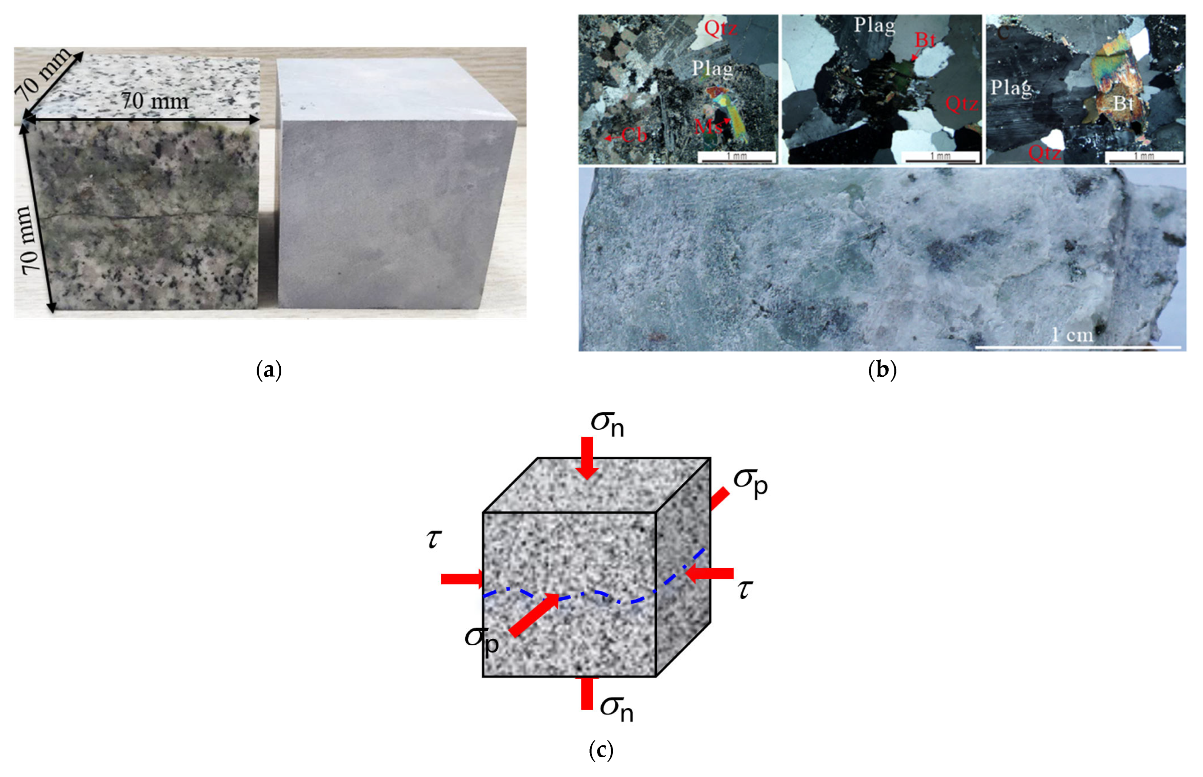
The specimens used in the multi-stage true triaxial direct shear test are jointed granite and intact CJPL-II marble, as shown in Figure 1. CJPL-II marble is used because of its good homogeneity, allowing it to verify the reliability of the test results obtained for jointed granite. The jointed granite was taken from a tunnel construction site, and the marble specimens were taken from the deep tunnels at the Jinping Underground Laboratory (CJPL-II) in China. All specimens were processed into cubic rock specimens of 70 mm (length) × 70 mm (width) × 70 mm (height). The perpendicularity tolerance was controlled within 0.025 mm when grinding the end surfaces, and the end surface finish was Ra < 1.6.
The main mineral composition and content of the jointed granite are quartz (40%), feldspar (45%), mica + chlorite (10%), and carbonate (5%). Among them, the quartz grain size is approximately 1.5 mm; the feldspar is mainly plagioclase, with a grain size of approximately 3 mm. The joint is formed by chloritization, while the part far away from the green joint is almost unchanged. Biotite mostly occurs during chloritization, and the content of biotite and chlorite is approximately 6%. Carbonate minerals are only located at the joint, mainly distributed in the interior of feldspar grains or along the contact interfaces between feldspar and feldspar or feldspar and quartz; no carbonate is observed between quartz grains. The CJPL-II marble specimens contain two main mineral components, namely, dolomite (89.1%) and calcite (10.9%), and have a density of approximately 2.82 g/cm3.
The basic mechanical properties of the rocks were determined from standard laboratory tests. The jointed granite had a uniaxial compressive strength (UCS) of 170.5 MPa and a tensile strength of 10.0 MPa. The intact CJPL-II marble had a UCS of 135.0 MPa and a tensile strength of 7.0 MPa.

2.2. Testing Program

Distinct from true triaxial creep-shear tests aimed at studying time-dependent behavior, the primary objective of the present MTTDS method is the efficient determination of the peak shear strength envelope. Its novelty is embodied in the loading path design: (1) lateral stress is maintained as an independent, servo-controlled variable throughout the shearing stage, thereby explicitly simulating the intermediate principal stress effect; (2) predefined multistage loading paths with strict pre-peak unloading are employed to obtain multiple strength data points while minimizing cumulative damage; (3) the output directly informs the engineering-standard Mohr–Coulomb failure criterion, quantifying the evolution of cohesion (c) and friction angle (φ) with sp, thereby building a direct bridge between three-dimensional in situ stress and two-dimensional strength analysis.
Most of the underground engineering rock mass is in a three-dimensional stress state with unequal three-dimensional principal stress. Considering only the normal stress and ignoring the influence of lateral stress cannot reveal the mechanical characteristics of the actual engineering rock mass at the true stress level. In order to study the influence of lateral stress on the shear results, a series of multistage true triaxial direct shear tests was carried out on two types of rocks.
In the context of this true triaxial direct shear test, the applied stresses are defined relative to the fixed orientation of the specimen and shear box. The normal stress is applied perpendicular to the predefined, simulated discontinuity plane (the x–y plane). The shear stress is applied parallel to this plane along the x-direction. The lateral stress is applied perpendicular to both the shear direction (x) and the normal stress direction (z), acting along the y-axis.
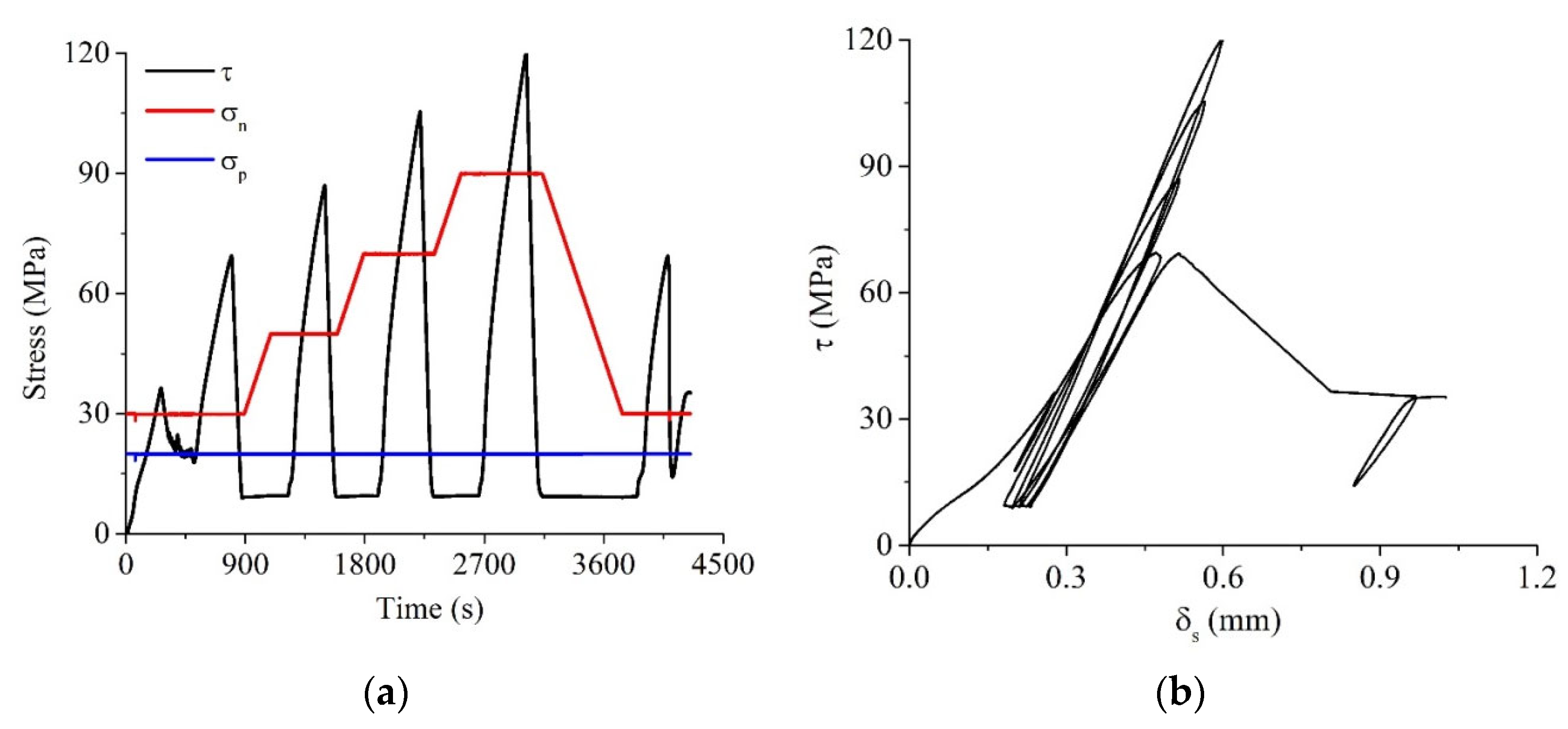
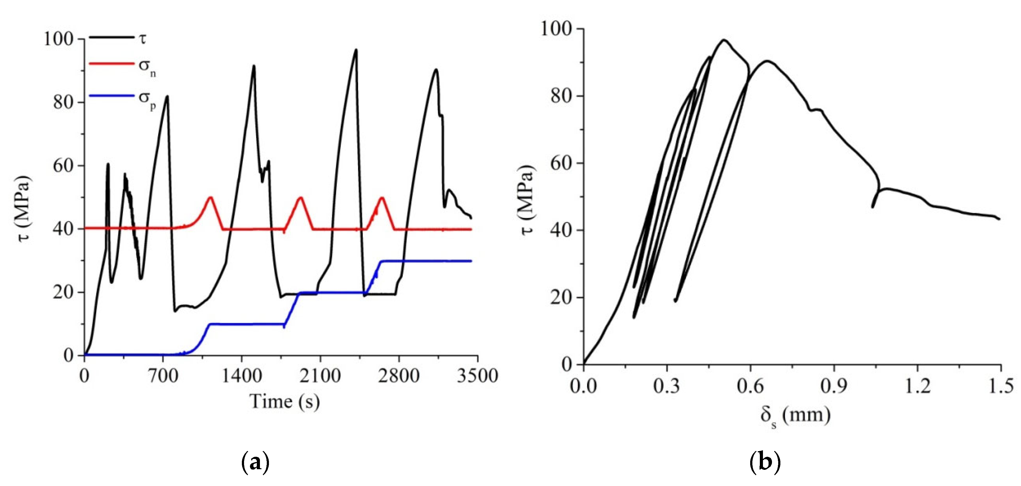
Table 1 presents the specimen numbers and the relevant test scheme. According to the different loading paths, the tests were divided into two types: the increasing σn multistage true triaxial direct shear test (INMDS) and the increasing σp multistage true triaxial direct shear test (ILMDS). The corresponding stress paths are shown in Figure 2a and Figure 3a. For the INMDS, the lateral stress and normal stress were first loaded at a rate of 0.1 MPa/s until reaching the preset lateral stress level. The lateral stress remained unchanged, and the normal stress was loaded to the target level at a loading rate of 0.5 kN/s. After that, the lateral stress and normal stress remained constant, and the shear force was loaded by displacement control alone at 0.002 mm/s until the slope of the curve of shear force and shear displacement approached 0. Then, the shear force was unloaded rapidly. The normal stress was loaded to the next preset level, and the shear stress was loaded until the slope of the shear force and shear displacement curve approached 0. Then, the shear force was unloaded quickly. This step was repeated until the end of the test. In the ILMDS test, the lateral stress and normal stress were simultaneously loaded by oil pressure at the rate of 0.1 MPa/s until the preset lateral stress level was reached. The lateral stress remained unchanged, and the normal stress was loaded to the target level at the loading rate of 0.5 kN/s. After that, the lateral stress and normal stress remained constant, and the shear force was loaded by displacement control alone at 0.002 mm/s until the slope of the curve of shear force and shear displacement approached 0. Then, the shear force was unloaded rapidly. The lateral stress was loaded to the next preset level (the normal stress was unloaded at the same time), and the shear stress was loaded until the slope of the shear force and shear displacement curve approached 0. Then, the shear force was unloaded quickly. This step was repeated until the end of the test.

3. Results

Figure 2 and Figure 3 illustrate two typical test results from the multistage true triaxial direct shear tests. In order to adjust the position of the servo motor screw, a small shear force was loaded and unloaded in the early stage of the test, which can also eliminate the influence of the testing machine and shear box on AE results. In order to avoid the actuator of the testing machine moving to the lower limit, the shear force in the figures is not unloaded to 0. In addition, due to the phenomenon of unloading after the peak in the third stage of the test in Figure 3, no repeat test of the last stage was carried out.
According to the analysis of shear stress and shear displacement, the curve can be divided into five stages: compaction stage, elastic deformation stage, plastic deformation stage, strain softening stage, and residual friction stage. Granite with discontinuities exhibits high brittleness, which is demonstrated by a sudden drop in the shear strength of the discontinuity in the stage of strain softening, while that of marble is relatively slow in the stage of strain softening.

3.1. Validation of the Multistage True Triaxial Direct Shear Test

One of the most important requirements of the multistage true triaxial direct shear test is that the shear force at each stage should not exceed the peak strength; that is, the unloading of shear force should be carried out before the peak, rather than after the peak. The last stage of the test in Figure 3 displays the typical post-peak unloading test results. In the third stage of the shear test, when the slope of the shear force and shear displacement curve is close to zero, the specimen suddenly enters the strain softening stage. The specimen bears a large shear displacement, and unloading is carried out after the shear force exceeds the peak strength. In the fourth stage of the shear test, the lateral stress increases from 20 MPa to 30 MPa. Although the increase in the lateral stress is expected to increase the shear strength of the specimen, the shear force does not increase but rather decreases. According to Figure 3, the shear stress and shear displacement curve should be monitored in real time during the test to prevent the shear force from exceeding the peak strength and unloading in time to avoid entering the strain softening stage so as to ensure the accuracy of the test results.
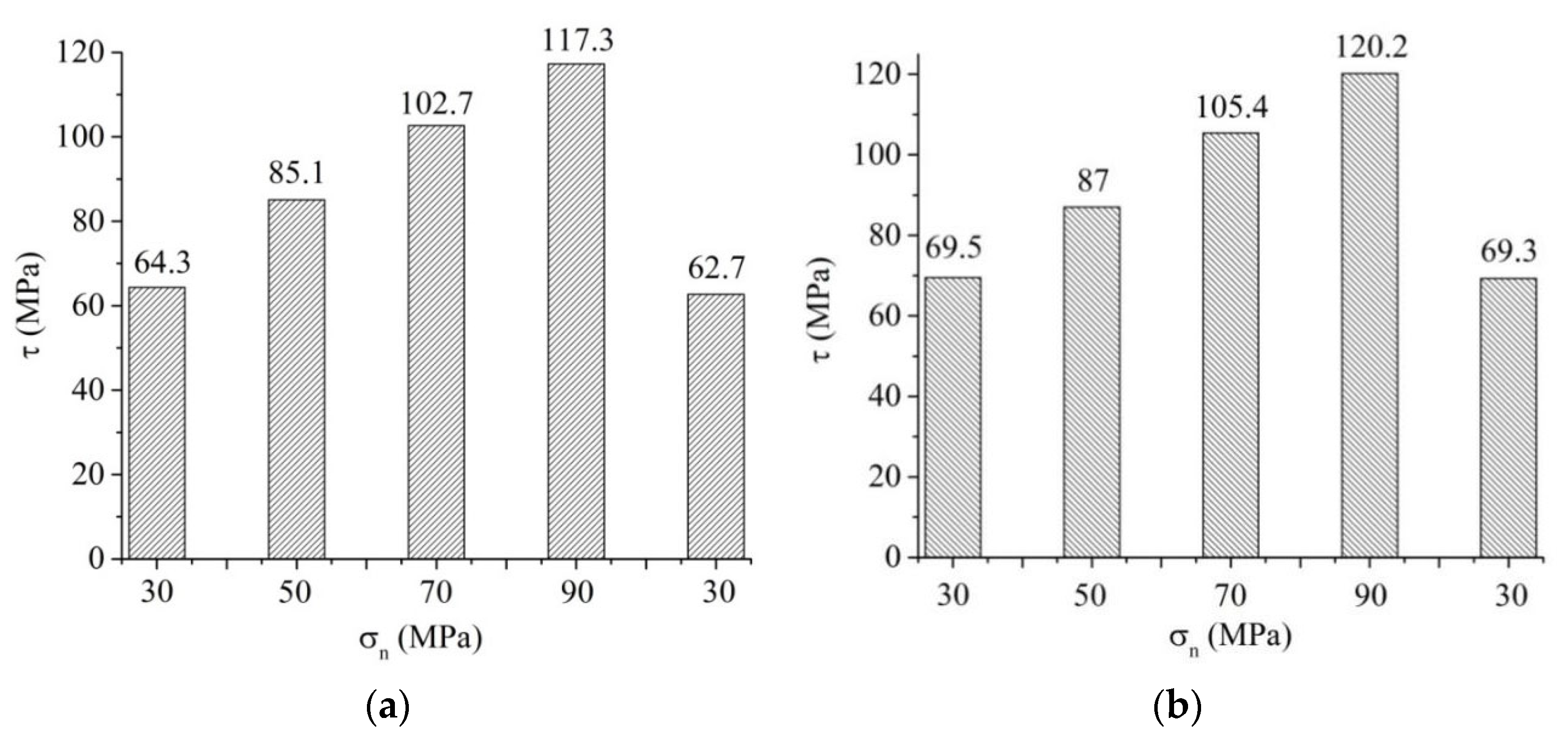
Another method to determine the validity of the multistage true triaxial direct shear test is to repeat the first-stage test at the last stage. Figure 4 shows the shear strength at each stage of the two INMDS tests. Under different lateral stress, two of the jointed granite specimens are sheared in five stages. Comparing the first-stage shear strength (S1) and the last-stage shear strength (S5) of the two specimens, it can be found that although the two specimens have experienced different loading histories, their S1 and S5 are almost the same. This shows that the multistage test can be carried out for up to five stages of loading, and the reliable strength parameters can still be obtained. It also shows that unloading before peak strength can effectively reduce the strength damage caused by each stage of loading, which proves the effectiveness of the multistage loading test.
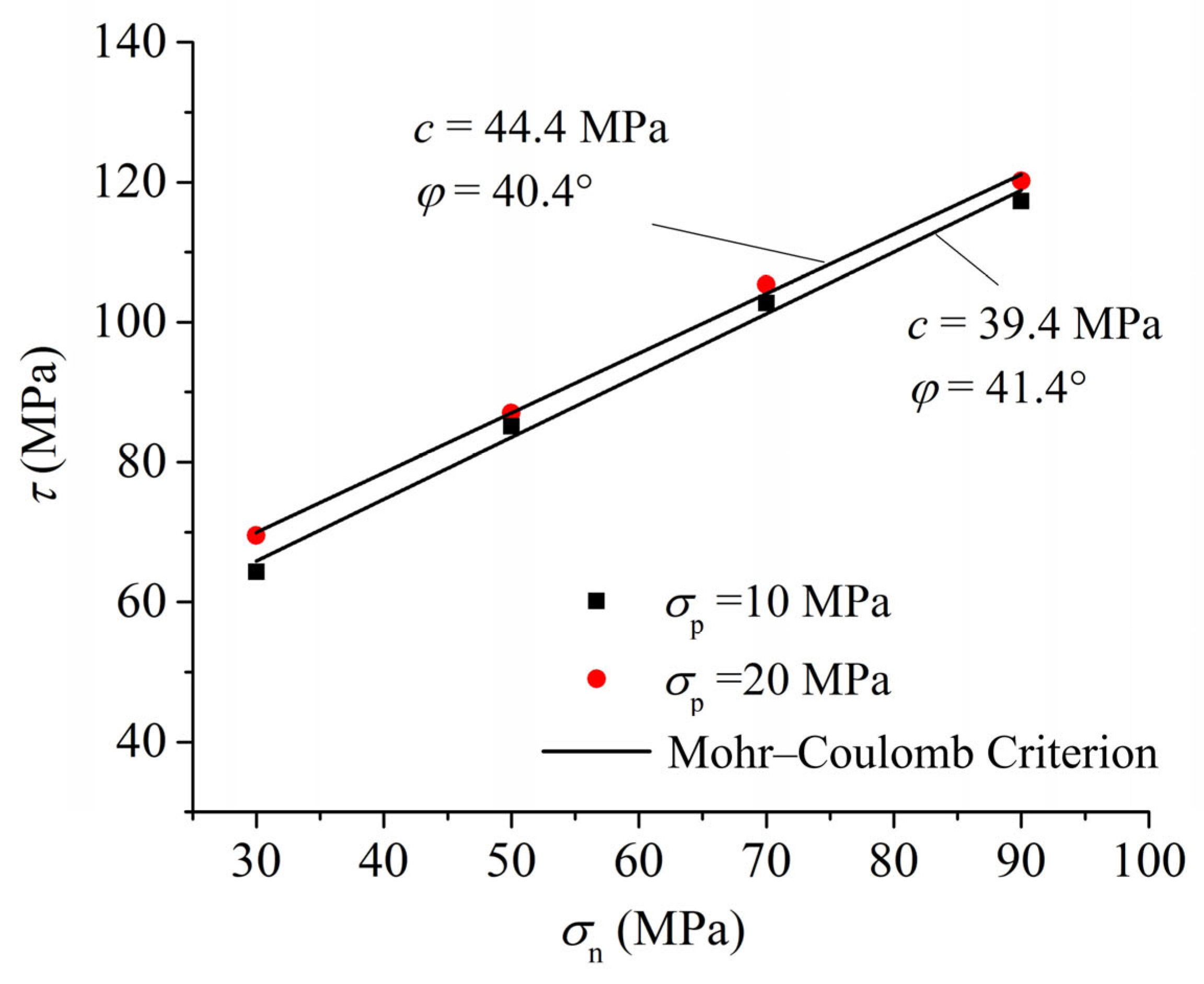
The Mohr–Coulomb criterion was applied to the experimental data by performing a linear least-squares regression between the peak shear strength and the corresponding normal stress at each constant lateral stress level. For a given σp, the cohesion (c) was obtained as the intercept of the fitted line at σn = 0, and the internal friction angle (φ) was calculated from the slope. This procedure was repeated for each lateral stress level to generate the series of failure envelopes presented in Figure 5.

3.2. Influence of Lateral Stress on Peak Shear Strength of Hard Rock

Extensive research has been conducted on the influence of normal stress on the shear strength of rock, leading to several classical shear strength criteria. In contrast, studies examining the effect of lateral stress on shear behavior remain limited, particularly under true triaxial stress conditions.
Figure 5 presents the test results for jointed granite. The Mohr–Coulomb strength criterion was used to fit the two sets of test data. It can be observed that as lateral stress increases, the cohesion (c) of the jointed granite specimen increases, while its internal friction angle (φ) decreases slightly. This indicates that applying lateral stress compacts the specimen, enhances the cohesive forces between micro-particles in the jointed granite, and thereby improves its shear strength.
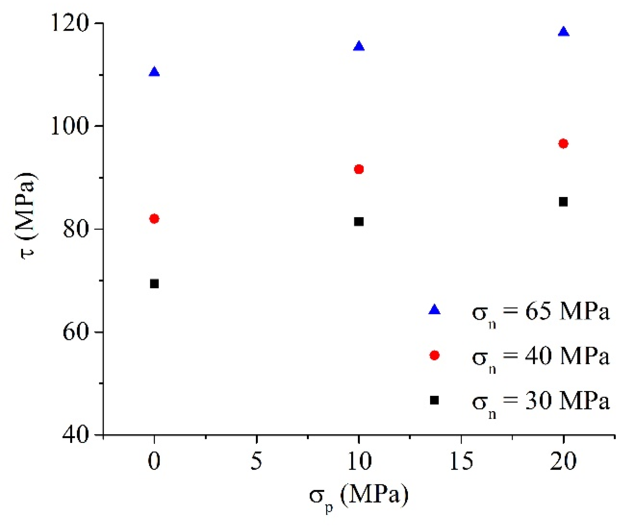
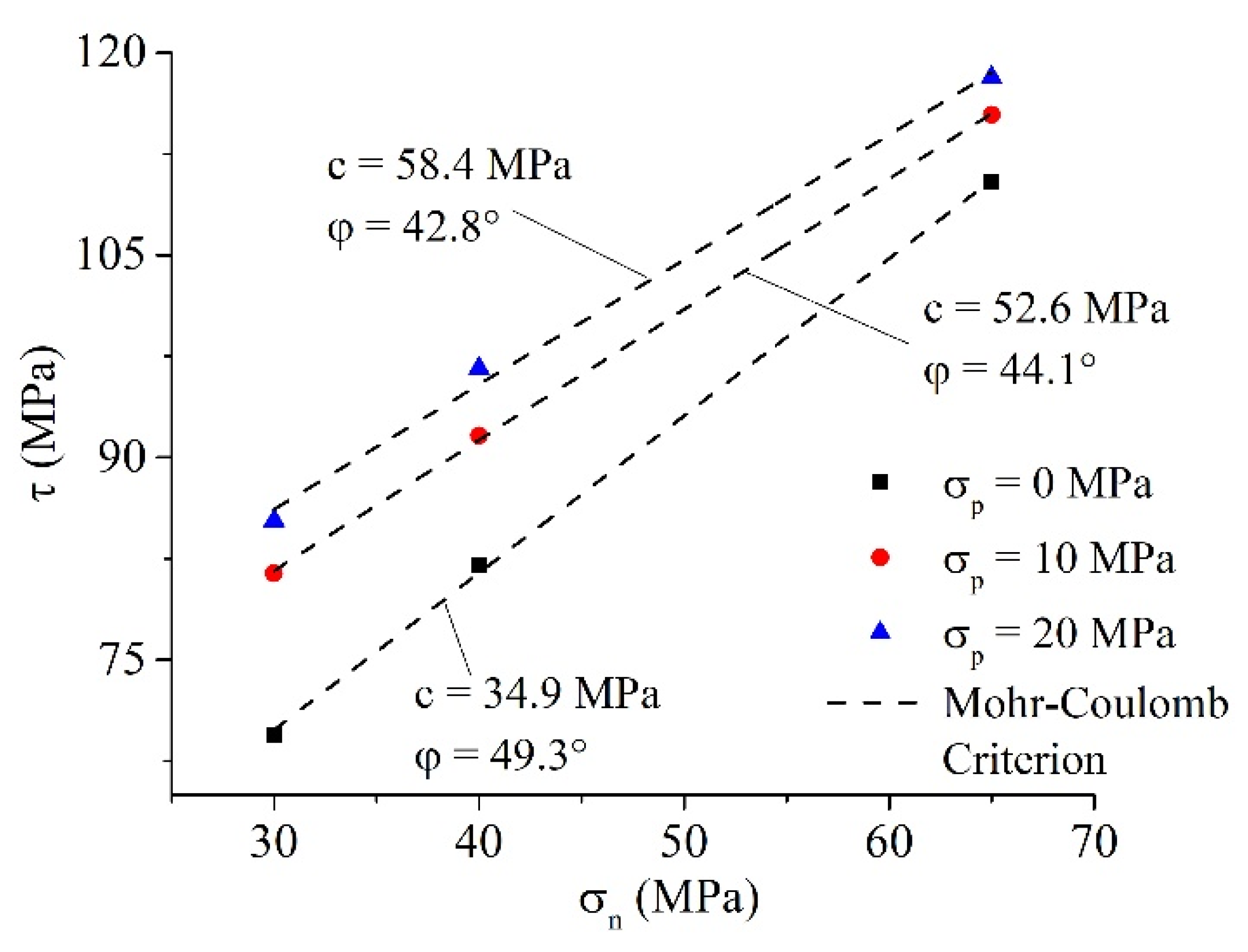
The slight decrease in φ is also consistent with the test results for CJPL-II marble (Figure 6 and Figure 7), which show that the enhancing effect of lateral stress on shear strength gradually diminishes with increasing σp. Owing to the good homogeneity of CJPL-II marble, an ILMDS test was performed to further verify the influence of lateral stress on shear strength. As shown in Figure 6, for intact marble specimens, lateral stress strengthens the shear strength, but the magnitude of increase gradually reduces as lateral stress rises, a trend analogous to the intermediate principal stress effect observed in true triaxial compression tests. This further supports the findings from jointed granite.
Using the Mohr–Coulomb criterion to fit the test results, it is evident that the cohesion continues to increase while the friction angle gradually declines. Analysis of the influence of lateral stress on the shear strength of hard rock suggests that when lateral stress is present during shearing, the rock undergoes additional compaction under its action. This behavior may be attributed to two interrelated mechanisms: on one hand, lateral stress may increase the cohesive bonding between micro-particles of the hard rock, leading to a higher c value; on the other hand, compaction induced by lateral stress may also reduce internal voids and suppress the development of microcracks, resulting in a decrease in the φ value.

3.3. Failure Characteristics and Fracture Mechanism Under True Triaxial Direct Shearing

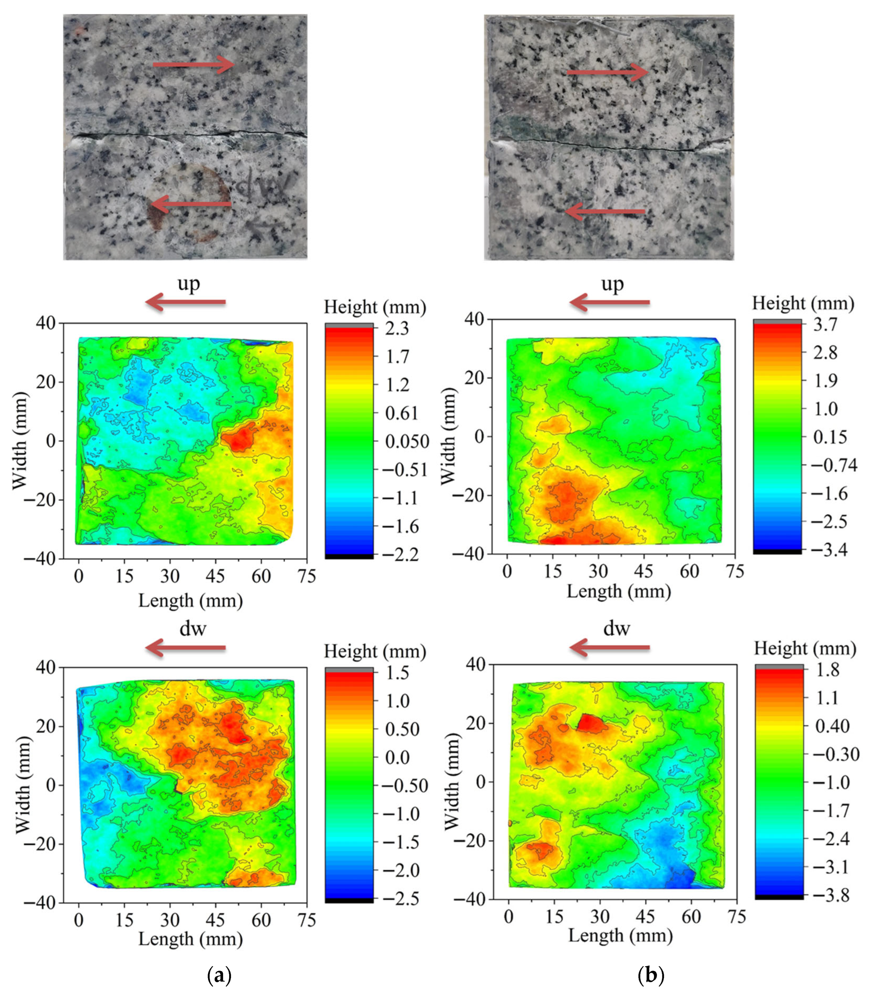
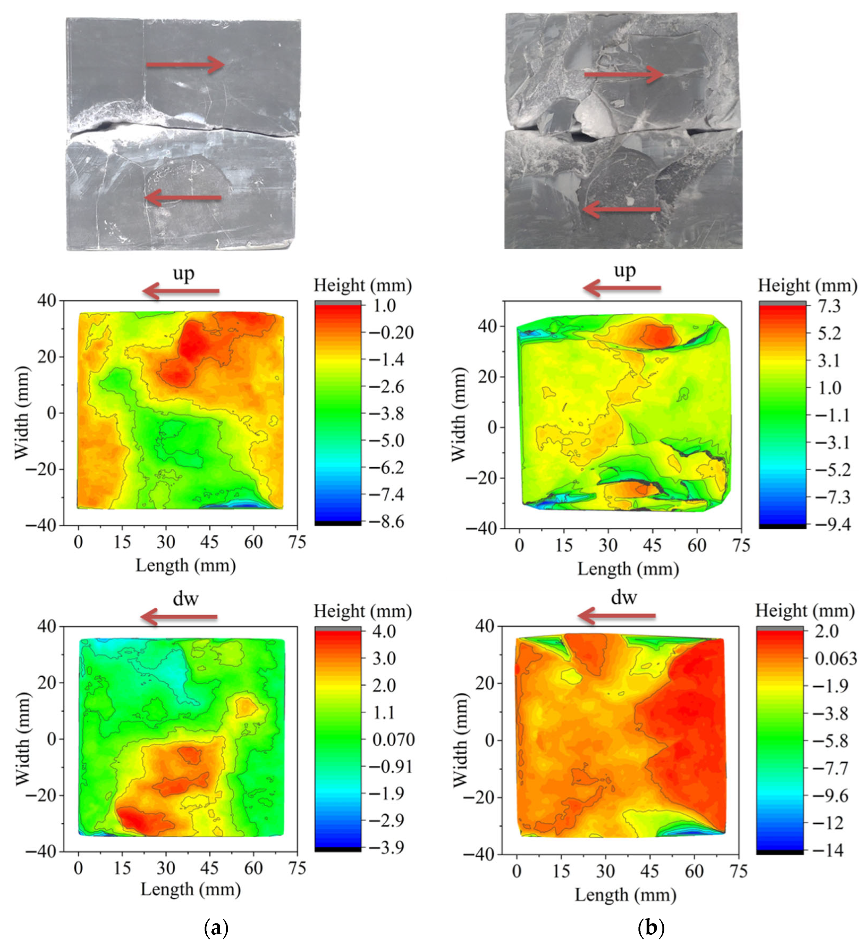
Figure 8 and Figure 9 show the failure diagram and cloud map of the failure surface of jointed granite and marble, respectively. It can be seen from the figure that the failure surface of the jointed granite is more gentle than that of the intact marble specimen, and there is no side spalling phenomenon. With the increase in σn, the shear plane of intact marble tends to be gentle, but the depth of lateral spalling increases gradually. As shown in Figure 9, when the normal stress is 40 MPa, there is only a small amount of spalling near the shear plane, while when the normal stress is increased to 65 MPa, more lateral spalling occurs in the upper part of the marble sample, which extends to the inner part of the specimen, and only about 60% of the upper and lower shear planes interact in the residual stage.
The transition in failure morphology can be understood through the interplay between shear-driven failure and tensile opening, as influenced by the three-dimensional stress state. Under lower lateral confinement, the rock is more susceptible to dilatant behavior during shearing. This allows for microcrack opening and propagation perpendicular to the shear direction, manifesting as the lateral spalling observed in marble (Figure 9a). This dilatant, high-friction mechanism is associated with a higher apparent friction angle.
With increased lateral stress, the enhanced confinement significantly suppresses this dilatant tendency. The stress state promotes a more compressive and localized shear failure. Microcracks are inhibited from opening laterally and are instead forced to interact and coalesce along a more confined, primary shear plane. This leads to the observed smoother fracture surfaces in granite (Figure 8b) and reduced spalling in marble at higher σn. Macroscopically, this shift corresponds to the noted increase in apparent cohesion and the slight decrease in internal friction angle, reflecting a change from a friction- and dilation-dominated failure to one where the shearing through a compacted, interlocked zone becomes predominant.
The strategy of “pre-peak unloading” in the multistage loading process is key to controlling this damage progression. Unloading before the peak shear strength is reached prevents the accumulated microcracks from coalescing into a through-going, critically damaged plane. This allows the specimen to retain its load-bearing fabric for subsequent loading stages. Conversely, post-peak unloading allows the main shear plane to fully form, irreversibly damaging the specimen’s structure and invalidating further strength tests at increased confinement, as evidenced by the strength loss in Stage 4 (Figure 3).

3.4. AE Characteristics and AE Hypocenter Locations in the Jointed Granite Under Multistage Loading

Acoustic emission (AE) monitoring provides real-time insight into microcrack evolution during shear. Figure 10 presents the time–history curves of shear stress, AE count, and cumulative AE count for jointed granite under varying σn.
In this study, AE monitoring was employed not only to identify the stress level associated with microcrack initiation (coinciding with peak strength) but, more importantly, to trace the evolution of damage accumulation and to evaluate the effectiveness of the multistage loading protocol. By comparing AE activities during pre-peak and post-peak unloading stages, the method provides direct insight into whether the loading history has induced new, extensive fracturing or has merely reactivated existing microcracks.
In the first stage, a pronounced AE count peak coincides with the peak shear strength, indicating significant microcrack initiation on the nascent shear surface. In contrast, the second and third stages exhibit markedly lower AE activity at their respective peaks. The cumulative AE count increases steadily without abrupt jumps, suggesting that once initial microcracks are generated, subsequent loading stages primarily reactivate and extend these existing defects rather than creating extensive new fracture networks. This pattern validates that pre-peak unloading effectively minimizes incremental damage, preserving the specimen’s integrity for reliable multistage testing.
The fourth stage deviates from this trend. Due to delayed unloading in the preceding stage (entering the strain softening regime), a sharp surge in AE count occurs, reflecting widespread new microcrack generation and propagation along the shear surface. A subsequent reloading at the same stress level produced no detectable AE, consistent with the Kaiser effect, confirming that the previous unloading point had already exceeded the material’s stress memory.
In the final stage, which repeats the first stage’s stress conditions, AE activity spikes again at peak stress as the specimen undergoes final rupture. The peak shear strength here (62.7 MPa) is slightly lower than in the first stage (64.3 MPa), attributable to the cumulative damage from the earlier over-unloading event. During the residual stage, steady AE signals correspond to frictional sliding and wear along the established shear plane.
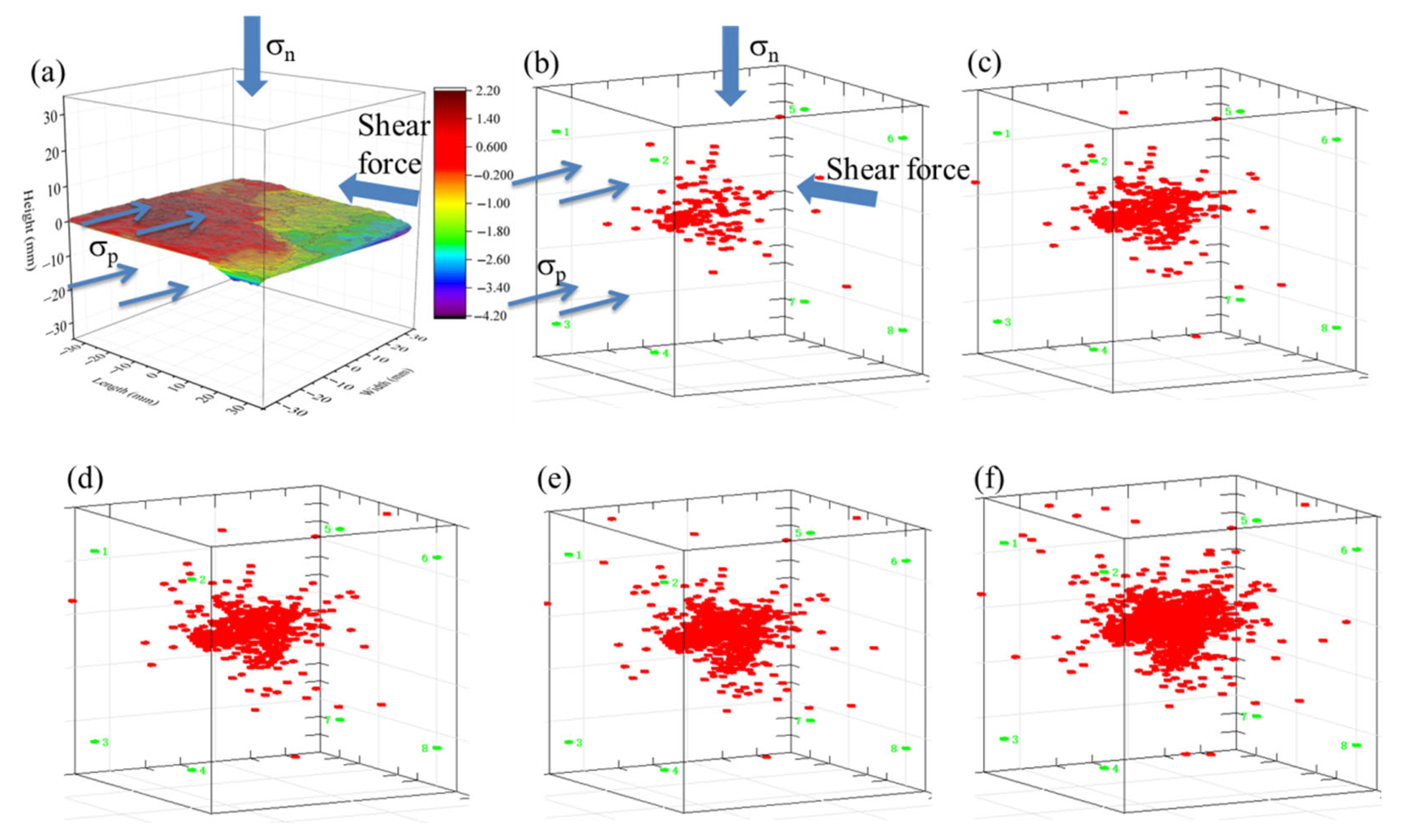
Figure 11 further visualizes this process through AE hypocenter locations at each peak stage. The spatial evolution of microcracks aligns closely with the final observed fracture pattern. AE events initially appear sparsely (stage 1, Figure 11b), increase moderately as loading progresses (stages 2 and 3; Figure 11c,d), and then proliferate dramatically following the late-unloading incident (stage 4, Figure 11e), culminating in dense clustering at final failure (last stage, Figure 11f). This progression confirms that controlled multistage loading confines damage development, whereas a single instance of post-peak unloading can accelerate fracture coalescence and compromise strength in later stages.
While AE monitoring effectively delineated damage states in this study, the analysis focused on count rates and spatial evolution. The acquisition of advanced parameters such as b-value or energy release was beyond the scope of this experimental campaign but represents a valuable target for future, more detailed investigations into the micromechanics of shear failure under confinement.

3.5. Limitations and Perspectives

The main findings are based on a limited number of specimens, which is characteristic of complex true triaxial tests. Although the multistage approach optimizes data acquisition per specimen, the absence of formal repeat tests precludes a rigorous statistical analysis of parameter scatter. The observed consistency across different stress paths and supporting evidence from acoustic emission monitoring indicate that the reported trend is robust and exceeds the estimated experimental scatter.
The quantitative results regarding the enhancement of cohesion and the slight reduction in the friction angle are specific to the tested hard rocks (granite and marble). The general physical mechanism of confinement-induced strengthening is expected to apply to other brittle rocks, but the exact magnitude of the effect may be lithology-dependent. Furthermore, the laboratory-scale experiments on prepared specimens may not fully represent the mechanical response of large-scale, naturally rough discontinuities under complex in situ stress paths. These scale and condition effects should be considered when extrapolating the results to field applications.
Finally, the validity of the proposed multistage true triaxial direct shear method fundamentally relies on the assumption that unloading is consistently performed before the peak strength is reached. This pre-peak unloading strategy, which minimizes cumulative damage, was successfully validated under the tested conditions. However, its efficacy and limits for a greater number of loading stages or for different rock types and initial damage states require further investigation.

4. Discussion

4.1. Modification of the Adhesion–Friction Theory

To interpret the macro-scale enhancing effect of lateral stress on shear strength observed in the multistage tests, we introduce and extend the adhesion–friction theory from tribology to a three-dimensional stress state. This approach is adopted as a conceptual macro-mechanical model to link the applied lateral stress to the increased resistance measured in the tests, primarily through the mechanism of an increased real contact area. It does not propose a new micromechanical fracture criterion but provides a contact-based rationale for the macro-scale trend. The theory focuses on the influence of lateral stress on the real contact area.
The classical adhesion–friction theory posits that the real contact area of a structural surface constitutes only a portion of the apparent contact area, and the frictional resistance depends on the material’s mechanical properties and the effect of normal pressure. Under a normal load, the stress at the contact point reaches the material’s compressive yield limit, resulting in plastic deformation. Subsequently, the stress at the contact point remains constant, and any further increase in normal load is accommodated by an increase in the contact area.
In the traditional two-dimensional model (considering only normal stress σn and shear stress τ), the real contact area A can be expressed as
A = A 0 σ n 2 + a τ 2 σ y
where A0 is the apparent contact area, σy is the material yield strength, and a is a shear stress influence coefficient (typically between 3 and 4).
However, underground rock masses exist in a true triaxial stress state, where lateral stress σp is present during shearing. To account for this, the stress state at the contact point must be extended to three dimensions:
[ 0 0 τ 0 σ p 0 τ 0 σ n ]
To establish a constitutive relationship suitable for rock materials, the extended Drucker–Prager criterion is adopted as the yield condition:
J 2 = k b Ι 1
Here, I1 = σn + σp is the first stress invariant, and J2 is the second deviatoric stress invariant:
J 2 = 1 6 [ σ p 2 + ( σ p σ n ) 2 + σ n 2 ] + τ 2
To derive an expression for the real contact area that incorporates the effect of lateral stress, we proceed from the macroscopic yield condition. Substituting the expressions for I1 and J2 (Equations (2) and (4)) into the yield criterion (Equation (3)) gives the specific condition for yielding at the contact point:
1 6 [ σ p 2 + ( σ p σ n ) 2 + σ n 2 ] + τ 2 = k b ( σ n + σ p )
For the stress states investigated in this study (see Table 1), the normal stress is the dominant principal stress, and the applied lateral stress is of a comparable order of magnitude. Under this condition, and aiming to reconcile the macroscopic yield condition with the framework of adhesion–friction theory, Equation (5) can be mathematically approximated. The expression under the square root can be reformulated and approximated via methods like completing the square, leading to a form that highlights the coupled effect of the stresses:
1 3 ( σ p 2 + σ n 2 σ p σ n ) + τ 2 = ( σ n + β σ p ) 2 + γ τ 2 + ϵ
Here, β and γ are coefficients related to the material constants. The approximation inherent in this formulation, which omits the higher-order term ϵ, is justified within the experimental stress range of this study. For the tested conditions, the lateral confinement is moderate, with the ratio σp/σn typically not exceeding 0.75 (see Table 1). Consequently, ϵ, which scales principally with (σp/σn)2, is at least one order of magnitude smaller than the dominant terms retained in the expression. Its omission is therefore permissible for deriving a simplified functional form.
Based on this physically motivated approximation, we define the three-dimensional generalized effective stress at a micro-contact as
σ e q 3 D = ( σ n + d σ p ) 2 + e τ 2
The coefficients d and e (corresponding to β and γ in the approximation) are the stress influence coefficients to be determined experimentally. Taking a purely compressive stress path with negligible shear stress (τ = 0) as an example for conceptual explanation: under this condition, the macroscopic criterion approximates to σn + βσp ≈ constant, while the micro-model simplifies to σn + p = σy. Their equivalence requires d = β. Analysis of the approximation of the macroscopic criterion indicates that the coefficient β is a function of the material’s internal friction parameter B and the current stress ratio σp/σn, expressed as β ≈ [1 + 2B(σp/σn)]/[2 + B(1 + σp/σn)]. For typical hard rock materials, the parameter B is small (approximately 0.1–0.5), and within the experimental stress range, the above expression shows that β is always positive and less than 1.
When the stress at the contact point satisfies the yield condition, the real contact area relates to the equivalent stress state. Consequently, an expression for the real contact area incorporating lateral stress can be derived:
A = A 0 ( σ n + d σ p ) 2 + e τ 2 σ y
The resultant force R at the contact point can then be expressed as
R = A ( σ n + d σ p ) 2 + e τ 2
Yielding occurs when R = y, at which point the shear stress reaches its peak strength.
The theoretical framework employed in this analysis utilizes well-established constitutive models. The three-dimensional form of the Mohr–Coulomb criterion and the extended Drucker–Prager criterion are adopted as the foundational yield conditions to describe the stress state at asperity contacts. This study does not propose a new strength criterion. The primary theoretical contribution lies in the extension of the adhesion–friction theory from tribology to a three-dimensional stress state relevant to rock joints. This extension quantitatively incorporates the lateral stress into the calculation of the real contact area, thereby providing a contact-mechanics-based explanation for the observed macroscopic strengthening effect.
In the presented model, friction is incorporated through two interconnected aspects. First, at the micro-scale of asperity contacts, the shear stress component (τ) in the three-dimensional stress state and its contribution to the second deviatoric invariant collectively represent the frictional resistance to sliding at the interfaces. This establishes a fundamental link between the contact mechanics and the macroscopic shear force. Second, the model’s outcome, which is the increase in the resultant force at contacts due to an enlarged real contact area, directly translates into an enhanced macroscopic shear strength.
While the adhesion–friction theory provides a useful conceptual framework, its application to rough rock joints and intact rock shear is a simplification, as it does not fully capture the complexities of fracture-dominated failure and the evolution of surface morphology during shearing. The proposed extension of the adhesion–friction theory provides a macroscopic, contact-mechanics-based framework to rationalize the experimentally observed enhancement of shear strength with lateral confinement. Equation (9) demonstrates that the lateral stress contributes to an increase in the real contact area through the coefficient d. This theoretical prediction is consistent, at the macroscopic level, with the test results where the Mohr–Coulomb cohesion increases with σp, as a larger real contact area implies greater force is required to overcome adhesion and interlocking at asperities. The introduction of the σp term in the model physically corresponds to the alteration of the three-dimensional stress state at contact points by lateral confinement, aligning with the true polyaxial stress conditions of deep rock masses. The value of this model lies in explicitly incorporating lateral stress as a variable into the analytical expression for real contact area, thereby offering a contact-mechanics-based explanation for the observed increase in shear strength. It directly links the macroscopic strength enhancement to the increase in the resultant force at contacting asperities due to the enlarged contact area under three-dimensional confinement. While this study does not proceed to formulate a new strength criterion, the derived mathematical framework provides a foundational perspective and parameters that could inform the future development of three-dimensional shear strength criteria.

4.2. Mechanisms of Lateral Stress Influence on Shear Behavior

The interpretation of shear strength parameters, specifically the observed increase in cohesion and the slight decrease in the internal friction angle with rising lateral stress σp, requires an integrated analysis that combines the concepts of stress path, progressive damage, and the fundamental nonlinearity of rock strength. The multistage true triaxial direct shear test is not merely a tool for data collection but a process that reveals how strength evolves under a defined stress history.
The test protocols (INMDS and ILMDS) apply σp in conjunction with varying σn, creating unique three-dimensional stress paths for the incipient shear zone. A key finding is that the strengthening effect of σp is fully realized only when the specimen’s microstructure retains substantial integrity—that is, when unloading occurs pre-peak. In such a case, σp acts to compact the rock fabric within the developing shear band, inhibit the lateral propagation of tensile microcracks, and enhance the resistance of rock bridges and asperities. This compaction and stabilization of a damaged but not failed zone is macroscopically captured by the Mohr–Coulomb criterion as an increase in the apparent cohesion. It represents an enhanced stress threshold required to remobilize and coalesce the confined micro-fractures into a through-going rupture plane.
Concurrently, the suppression of dilatancy by lateral confinement shifts the failure mode from one characterized by high friction, asperity riding, and asperity breaking toward a shearing process that is more compressive and dominated by crushing. This micromechanical transition results in a lower mobilized friction angle when a linear strength envelope is fitted. This phenomenon is not an artifact but reflects a genuine change in the governing failure mechanism under increased confinement.
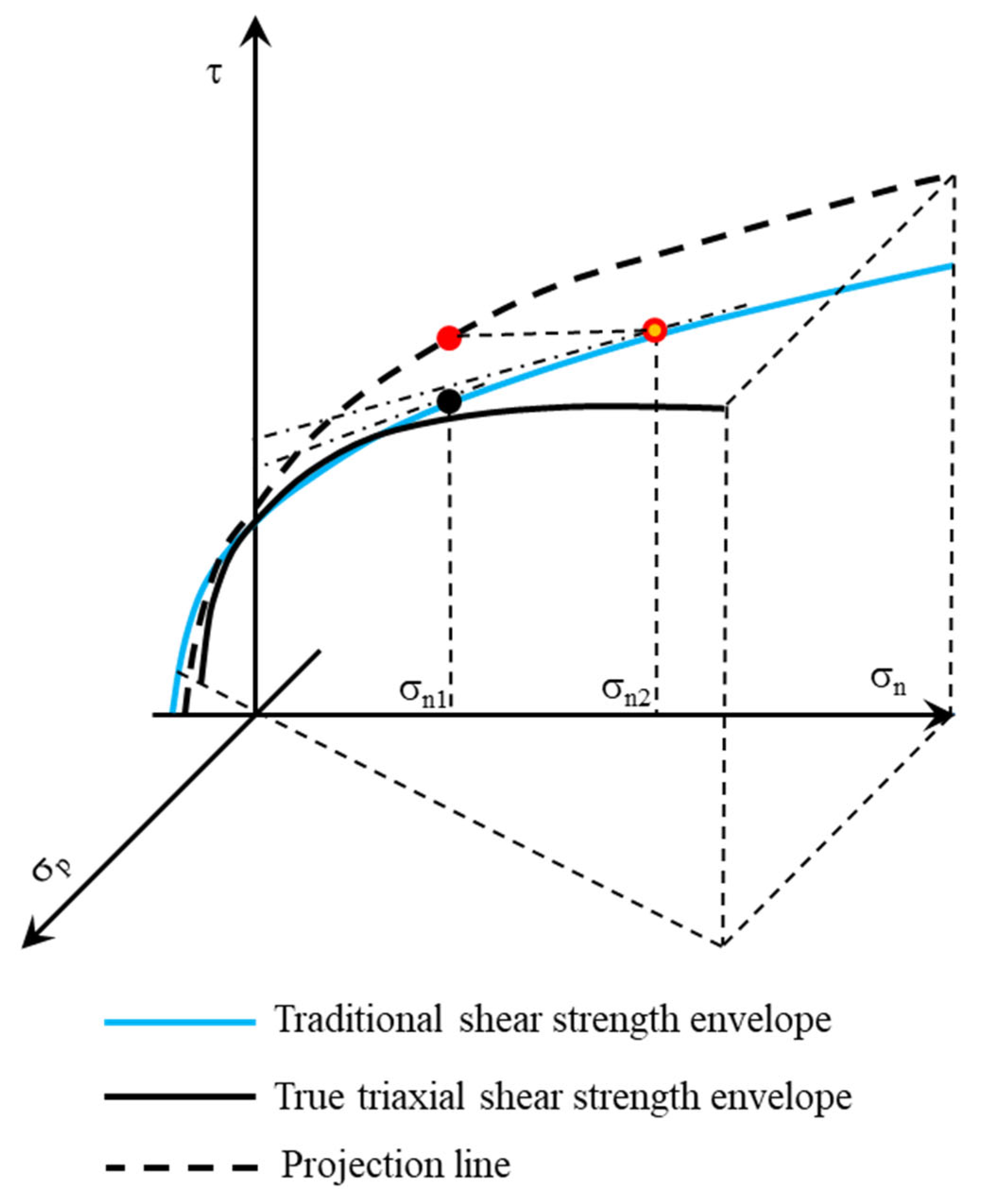
This interpretation is further reinforced by the concept of a parabolic rock strength envelope (Figure 12). The parabolic shape implies that the instantaneous friction angle decreases as the normal stress increases. The trajectory from point σpn1 to σn2 on this envelope shows precisely the trend observed in our tests: a higher intercept and a lower slope of the tangent line. The application of σp in our three-dimensional shear test effectively moves the stress state on the shear plane along a similar path on this intrinsic strength envelope, thereby explaining the coherent evolution of the fitted parameters. It is important to emphasize that within the context of this true triaxial direct shear test, the cohesion and friction angle obtained from linear Mohr–Coulomb fitting should be regarded as apparent strength parameters. Their values are strongly dependent on the applied stress state, particularly the level of lateral stress. The systematic increase in c with σp macroscopically represents the enhanced resistance due to more compact micro-contacts and strengthened rock bridges/asperities under higher confinement. The slight decrease in φ reflects the transition in the dominant failure mechanism from a high-friction, sliding/dilatancy-dominated mode towards a more pure compressive-shear mode as lateral confinement suppresses dilatant behavior. Therefore, these parameters are not intrinsic material constants but serve as effective and intuitive engineering metrics for quantifying the three-dimensional stress effect along specific stress paths (INMDS, ILMDS).
This insight has direct implications for support design in deep excavations. In contrast, within zones characterized by lower lateral stress, where tensile failure mechanisms such as spalling or rockburst are more prone to occur perpendicular to structural planes, the support design must fulfill a dual function. It should not only be configured to resist shear deformation along potential weak planes but also be specifically reinforced to supplement the deficient natural confinement in the lateral direction, thereby proactively suppressing these tensile failure modes.
The validity of this interpretation, which depends on the stress path, is corroborated by the acoustic emission (AE) evidence. The minimal AE activity in intermediate stages of a properly conducted test confirms that pre-peak unloading limits damage accumulation, allowing the specimen to retain a “memory” of its intact or jointed strength while being progressively conditioned by confinement. In contrast, a single post-peak unloading event causes a surge in AE activity, indicating widespread new damage that fundamentally resets the specimen’s response, invalidating the strengthening effect of subsequent increases in σp. Therefore, the successful measurement of the lateral stress effect is intrinsically linked to the controlled, incremental damage imposed by the multistage pre-peak unloading protocol.
It should be noted that while the multistage approach significantly enhances data yield per specimen, formal statistical error analysis based on repeat tests under identical stress paths was not performed due to the time and cost constraints typical of complex true triaxial experiments. This is a common characteristic of such exploratory methodological studies. However, the high degree of consistency in the strength evolution trends observed across different specimens and stress paths (INMDS and ILMDS), coupled with the supporting evidence from AE monitoring of damage evolution, indicates that the strengthening effect of lateral stress reported here is significant and robust, exceeding the expected scatter of the experimental data. Future work incorporating repeat tests would be valuable to further quantify the repeatability precision of the method.

5. Conclusions

This study was performed to determine the shear strength of rock under realistic three-dimensional stress conditions. It validates the multistage true triaxial direct shear test, where normal and lateral stresses are independently controlled, as a reliable method for obtaining complete failure envelopes from a single specimen. It systematically reveals and quantifies the significant strengthening effect of the intermediate lateral stress on the shear behavior of hard rock. The main conclusions are as follows:
(1) The multistage loading technique was successfully implemented in true triaxial direct shear testing. Its reliability was verified by comparing the shear strength of the first and final stages, demonstrating that pre-peak unloading effectively minimizes strength degradation, enabling a single specimen to yield a complete failure envelope across multiple loading stages.
(2) Lateral stress significantly enhances the peak shear strength of hard rock. This effect is characterized by a marked increase in the apparent cohesion of the specimen coupled with a slight decrease in its apparent internal friction angle with increasing σp. This quantitative relationship was obtained via linear Mohr–Coulomb fitting of the experimental data, which is valid within the tested ranges of σp and σn. It should be noted that c and φ, as apparent parameters, are dependent on the specific stress path and stress level experienced.
(3) Acoustic emission monitoring confirms that controlled multistage loading with pre-peak unloading restricts damage accumulation to microcrack reactivation, whereas post-peak unloading induces widespread new fracturing, which compromises the reliability of subsequent stages.
(4) The experimental trend of increased cohesion with lateral stress can be interpreted through an extended adhesion–friction theory framework. This macro-scale model suggests that lateral stress increases the real contact area at contacting asperities, thereby enhancing the macroscopic shear resistance, which aligns with the observed increase in the apparent cohesion parameter.
(5) From a stress path perspective, the application of lateral stress alters the failure mode from a dilatant, high-friction mechanism to a more compressive, crushing-dominated process. This shift, illustrated by the parabolic strength envelope, explains the concurrent increase in c and decrease in φ under elevated confinement.

Author Contributions

Conceptualization, G.W.; methodology, G.W., N.L. and Q.H.; validation, G.W. and Y.G.; formal analysis, G.W.; investigation, G.W.; data curation, G.W.; writing—original draft preparation, G.W. and J.W.; writing—review and editing, Y.G. and Q.H.; visualization, J.W.; supervision, N.L. and Q.H.; project administration, N.L.; funding acquisition, N.L. All authors have read and agreed to the published version of the manuscript.

Funding

This research was funded by the Key Research Project of PowerChina (DJ-HXGG-2025-06).

Data Availability Statement

The datasets generated and analyzed during this study are available from the corresponding author upon reasonable request. This includes the raw and processed stress-displacement curves, acoustic emission event data, and macroscopic images of the failure surfaces.

Conflicts of Interest

Author Gang Wang, Yaohui Gao and Ning Liu were employed by the company PowerChina Huadong Engineering Corporation Limited. The remaining authors declare that the research was conducted in the absence of any commercial or financial relationships that could be construed as a potential conflict of interest.

References

  1. Kaiser, P.K.; Cai, M. Design of rock support system under rockburst condition. J. Rock Mech. Geotech. Eng. 2012, 4, 215–227. [Google Scholar] [CrossRef] [Scilit]
  2. Zhao, J.-S.; Duan, S.-Q.; Chen, B.-R.; Li, L.; He, B.-G.; Li, P.-X.; Liu, G.-F. Failure mechanism of rock masses with complex geological conditions in a large underground cavern: A case study. Soil Dyn. Earthq. Eng. 2024, 177, 108439. [Google Scholar] [CrossRef] [Scilit]
  3. Gong, F.; Wu, W.; Ren, L. Rockburst process and strength-weakening effect of the high-stress circular tunnel under internal unloading. J. Rock Mech. Geotech. Eng. 2023, 15, 864–885. [Google Scholar] [CrossRef] [Scilit]
  4. Xiong, Y.; Feng, X.-T.; Yao, Z.; Lv, B.; Xu, J.; Wang, Q.; Dou, F.; Hu, L.; Zhang, W. Study on the development mechanism of time-delayed strain rockbursts in deep granite tunnels excavated by TBM. Rock Mech. Rock Eng. 2025, 8, 405–430. [Google Scholar] [CrossRef] [Scilit]
  5. He, B.-G.; Liu, H.; Feng, X.-T.; Fu, H. Effect of dynamic disturbance frequency on brittle failure of granite in deep excavation. J. Rock Mech. Geotech. Eng. 2025, 18, 1002–1015. [Google Scholar] [CrossRef] [Scilit]
  6. Wu, Z.; Feng, X.-T.; Kong, R.; Yang, C.; Yao, Z. The Staged Development Process and Mechanism of Stress-Induced Collapse in a Deep Hard Rock TBM Tunnel. Rock Mech. Rock Eng. 2025, 58, 8493–8521. [Google Scholar] [CrossRef] [Scilit]
  7. Chu, C.; Xia, L.; Wu, S.; Han, S.; Zhang, G. Research on the Mechanical Behavior and Rockburst Risk of the Deep-Buried Roadway at the Stratigraphical Boundary of Different Lithologies. Appl. Sci. 2025, 15, 7026. [Google Scholar] [CrossRef] [Scilit]
  8. Yang, C.; Li, J.; Qian, Y.; Bo, W.; Zhang, G.; Zhao, C.; Zhao, K. Mechanisms of tunnel rockburst development under complex geostress gonditions in plateau regions. Appl. Sci. 2025, 15, 8517. [Google Scholar] [CrossRef] [Scilit]
  9. Jiang, Y.-J.; Xiao, J.; Tanabashi, Y.; Mizokami, T. Development of an automated servo-controlled direct shear apparatus applying a constant normal stiffness condition. Int. J. Rock Mech. Min. Sci. 2004, 41, 275–286. [Google Scholar] [CrossRef] [Scilit]
  10. Xia, C.-C.; Tang, Z.-C.; Xiao, W.-M.; Song, Y.-L. New Peak Shear Strength Criterion of Rock Joints Based on Quantified Surface Description. Rock Mech. Rock Eng. 2014, 47, 387–400. [Google Scholar] [CrossRef] [Scilit]
  11. Chen, B.; Shen, B.; Jiang, H. Shear behavior of intact granite under thermo-mechanical coupling and three-dimensional morphology of shear-formed fractures. J. Rock Mech. Geotech. Eng. 2023, 15, 523–537. [Google Scholar]
  12. Wang, G.; Li, H.; Liu, T. Study on the shear mechanical properties of non-penetrating joints with different apertures and connectivity rates. J. Min. Sci. Technol. 2025, 10, 607–617. [Google Scholar] [CrossRef]
  13. Li, Y.; Xia, Z.; Shan, C.; Xu, Q.; Yao, Q.; Li, H. Influence of Tiered Cyclic Shear Stress on Shear Friction and Instability Behavior of Marble Specimens with the Fractures. Appl. Sci. 2025, 15, 10308. [Google Scholar] [CrossRef] [Scilit]
  14. Hou, Y.; Shao, L.; Guo, X. Dependence of Interface Shear Strength of Sand on Surface Roughness and Particle Size. Appl. Sci. 2025, 15, 9575. [Google Scholar] [CrossRef] [Scilit]
  15. Zhang, C.; Feng, X.-T.; Zhou, H.; Qiu, S.; Yang, Y. Rock mass damage induced by rockbursts occurring on tunnel floors: A case study of two tunnels at the Jinping II Hydropower Station. Environ. Earth Sci. 2014, 71, 441–450. [Google Scholar] [CrossRef] [Scilit]
  16. Xie, H.; Lu, J.; Li, C.; Li, M.; Gao, M. Experimental study on the mechanical and failure behaviors of deep rock subjected to true triaxial stress: A review. Int. J. Min. Sci. Technol. 2022, 32, 915–950. [Google Scholar] [CrossRef] [Scilit]
  17. Mogi, K. Fracture and flow of rocks under high triaxial compression. J. Geophys. Res. 1971, 76, 1255–1269. [Google Scholar] [CrossRef] [Scilit]
  18. Ingraham, M.D.; Issen, K.A.; Holcomb, D.J. Response of Castlegate sandstone to true triaxial states of stress. J. Geophys. Res. Solid Earth 2013, 118, 536–552. [Google Scholar] [CrossRef] [Scilit]
  19. Ma, X.; Haimson, B.C. Failure characteristics of two porous sandstones subjected to true triaxial stresses. J. Geophys. Res. Solid Earth 2016, 121, 6477–6498. [Google Scholar] [CrossRef] [Scilit]
  20. Feng, X.-T.; Zhang, X.; Kong, R.; Wang, G. A novel Mogi type true triaxial testing apparatus and its use to obtain complete stress–strain curves of hard rocks. Rock Mech. Rock Eng. 2016, 49, 1649–1662. [Google Scholar] [CrossRef] [Scilit]
  21. Hu, L.; Yu, L.; Ju, M.; Li, X.; Tang, C. Effects of intermediate stress on deep rock strainbursts under true triaxial stresses. J. Rock Mech. Geotech. Eng. 2023, 15, 659–682. [Google Scholar] [CrossRef] [Scilit]
  22. Wang, G.; Feng, X.-T.; Yang, C.; Zhao, J.; Xiong, Y.; Wang, J. Effect of lateral stress on shear strength of jointed hard rocks in true triaxial single-shear test. Bull. Eng. Geol. Environ. 2023, 82, 463. [Google Scholar] [CrossRef] [Scilit]
  23. Zhao, J.; Feng, X.-T.; Wang, J.-R.; Hu, L.; Guo, Y. A multifunctional shear apparatus for rocks subjected to true triaxial stress and high temperature in real-time. J. Rock Mech. Geotech. Eng. 2024, 16, 3524–3543. [Google Scholar] [CrossRef] [Scilit]
  24. Zheng, Z.; Ma, Z.; Qi, J.; Su, G.; Lu, G.; Pei, S.; Jiang, Q. Multi-directional disturbance effect of shear mechanical behaviors and fracturing mechanisms of rockmass intermittent structural plane under true triaxial shear test. Int. J. Min. Sci. Technol. 2025, 35, 933–960. [Google Scholar] [CrossRef] [Scilit]
  25. Wang, J.; Feng, X.-T.; Zhao, J.; Yang, C.-X.; Hu, L.; Guo, Y. True triaxial shear creep behaviors of sandstone under constant normal load and constant normal stiffness conditions. J. Rock Mech. Geotech. Eng. 2024, 17, 5053–5065. [Google Scholar] [CrossRef] [Scilit]
  26. Wang, J.; Feng, X.-T.; Zhao, J.; Yang, C.-X. Progressive cracking mechanism in natural hard structural planes under creep shear testing with lateral stress unloading. Eng. Geol. 2025, 359, 108445. [Google Scholar] [CrossRef] [Scilit]
  27. Zhao, J.-S.; Chen, B.-R.; Jiang, Q.; Xu, D.-P.; He, B.-G.; Duan, S.-Q. In-situ comprehensive investigation of deformation mechanism of the rock mass with weak interlayer zone in the Baihetan Hydropower Station. Tunn. Undergr. Space Technol. 2024, 148, 105690. [Google Scholar] [CrossRef] [Scilit]
  28. Nam, S.; Gutierrez, M.; Diplas, P.; Petrie, J. Determination of the shear strength of unsaturated soils using the multistage direct shear test. Eng. Geol. 2011, 122, 272–280. [Google Scholar] [CrossRef] [Scilit]
  29. Wang, G.; Feng, X.-T.; Yang, C.; Han, Q.; Kong, R. Experimental Study of the Mechanical Characteristics of Jinping Marble Under Multi-stage True Triaxial Compression Testing. Rock Mech. Rock Eng. 2022, 55, 953–966. [Google Scholar] [CrossRef] [Scilit]
  30. Gaines, S. Interpretation of the Peak and Residual Strength of Induced Tension Fractures in Sandstone by Single-Stage and Multi-Stage Direct Shear Tests. In Proceedings of the 54th U.S. Rock Mechanics/Geomechanics Symposium, Virtual, 28 June–1 July 2020; p. ARMA-2020-1560. [Google Scholar]
  31. Youn, H.; Tonon, F. Multi-stage triaxial test on brittle rock. Int. J. Rock Mech. Min. Sci. 2010, 4, 678–684. [Google Scholar] [CrossRef] [Scilit]
  32. Yang, S.-Q. Strength and deformation behavior of red sandstone under multi-stage triaxial compression. Can. Geotech. J. 2012, 49, 694–709. [Google Scholar] [CrossRef] [Scilit]
Figure 1. Rock specimens: (a) Typical jointed granite specimen and CJPL-II marble specimen; (b) microstructural diagram showing the main minerals (polarized light graph); (c) schematic diagram of the force on a true triaxial shear specimen.
Applsci 16 02288 g001
Figure 2. Typical result of INMDS (JG2): (a) stress vs. time; (b) shear stress vs. horizontal displacement.
Applsci 16 02288 g002
Figure 3. Typical result of ILMDS (JP2): (a) stress vs. time; (b) shear stress vs. horizontal displacement.
Applsci 16 02288 g003
Figure 4. Relation between the shear strength and σn: (a) σp = 10 MPa; (b) σp = 20 MPa.
Applsci 16 02288 g004
Figure 5. Failure envelopes determined from the multistage true triaxial direct shear tests on jointed granite.
Applsci 16 02288 g005
Figure 6. Relation between the shear strength and the lateral stress of CJPL-II marble.
Applsci 16 02288 g006
Figure 7. Failure envelopes determined from the multistage true triaxial direct shear tests on CJPL-II marble.
Applsci 16 02288 g007
Figure 8. The failure diagram and cloud map of the failure surface of jointed granite: (a) σp = 10 MPa; (b) σp = 20 MPa. The red arrows indicate the shear direction.
Applsci 16 02288 g008
Figure 9. The failure diagram and cloud map of the failure surface of marble: (a) σn = 40 MPa; (b) σn = 65 MPa. The red arrows indicate the shear direction.
Applsci 16 02288 g009
Figure 10. AE characteristics of granite under ILMDS.
Applsci 16 02288 g010
Figure 11. Microcrack evolution of jointed granite based on an analysis of the AE hypocenter location at different times and stresses: (a) Schematic diagram of specimen loading; (b) stage 1; (c) stage 2; (d) stage 3; (e) stage 4; (f) post-peak stage.
Applsci 16 02288 g011
Figure 12. Schematic diagram comparing the traditional shear strength envelope with the true triaxial shear strength envelope.
Applsci 16 02288 g012
Table 1. Test scheme of multistage true triaxial direct shear tests.
Nameσn
(MPa)
σp
(MPa)
Jointed GraniteJG10 → 50 → 70 → 90 → 3010
JG20 → 50 → 70 → 90 → 3020
MarbleJP130 0 → 10 → 20
JP240 0 → 10 → 20 → 30
JP365 0 → 10 → 20 → 30
Note: The arrows indicate the sequence of loading, representing a change in stress level from one value to another.
Disclaimer/Publisher’s Note: The statements, opinions and data contained in all publications are solely those of the individual author(s) and contributor(s) and not of MDPI and/or the editor(s). MDPI and/or the editor(s) disclaim responsibility for any injury to people or property resulting from any ideas, methods, instructions or products referred to in the content.