Article

Fuel-Efficient Coordinated Control Strategy for Medium-Voltage DC Shipboard Power Systems with Solid Oxide Fuel Cells and Variable-Speed Diesel Generators


School of Electrical Engineering, Kookmin University, 77, Jeongneung-ro, Seongbuk-gu, Seoul 02707, Republic of Korea
*
Author to whom correspondence should be addressed.
Appl. Sci. 2026, 16(4), 1694; https://doi.org/10.3390/app16041694
Submission received: 20 December 2025 / Revised: 3 February 2026 / Accepted: 5 February 2026 / Published: 8 February 2026
(This article belongs to the Special Issue Fuel Cell Technologies in Power Generation and Energy Recovery)

Abstract

This study proposes an advanced coordinated control strategy for a hybrid medium-voltage DC (MVDC) shipboard power system that integrates solid oxide fuel cells (SOFCs) and variable-speed diesel generators (VSDGs). The study aims to achieve superior fuel consumption reduction and enhanced power quality in marine environments. An SOFC dynamic model is developed to accurately capture electrochemical behavior and to evaluate efficiency under varying load factors. For the VSDG, a fuel consumption model incorporating variable rotational speed is derived, enabling the selection of an optimal operating speed that minimizes specific fuel consumption while maintaining system stability. The proposed strategy employs fuel-optimal integrated control to dispatch and regulate power sharing between SOFCs and VSDGs dynamically under varying load conditions using an upper-level controller. Simulation studies demonstrate that the proposed method ensures SOFC operation within high-efficiency utilization regions, adjusts VSDG speed to maximize fuel economy, and achieves stable load sharing through cooperative control. The results demonstrate significant fuel savings, with reductions of 75.3% under low-load conditions and 26.3% under high-load conditions compared with the non-coordinated baseline, contributing to the advancement of sustainable and reliable maritime electrification.

1. Introduction

The increasing global concern regarding climate change and environmental degradation is continuously putting the maritime sector under pressure to reduce its greenhouse gas emissions. In response, the International Maritime Organization (IMO) has established a strategic plan to reduce carbon emissions from ships by 50% by 2050, compared to the levels recorded in 2008 [1,2]. These ambitious targets are reshaping the landscape of marine propulsion and energy systems, pushing for the development and integration of environmentally friendly technologies on board ships. Among the various approaches considered to comply with IMO regulations, improving fuel consumption efficiency is recognized as a fundamental and practical solution. Efficient energy use not only contributes to reducing emissions but also enhances the overall economic performance of vessels by minimizing operational costs. This has motivated extensive research on alternative power generation systems and optimal energy management strategies for shipboard applications.
Fuel cells, particularly solid oxide fuel cells (SOFCs), have emerged as promising candidates for marine power systems owing to their high efficiency, low emissions, and modular design [3]. Unlike renewable energy sources, SOFCs do not rely on environmental conditions, thereby eliminating issues related to intermittency and variability [4]. Their ability to generate power steadily and cleanly makes them highly suitable for long-range or high-demand maritime operations. Among the various types of fuel cells, SOFCs are attractive for integration into large-scale ships owing to their superior energy conversion efficiency and compatibility with hydrocarbon fuels [5]. However, a critical limitation of SOFCs lies in their inherently slow dynamic response, which poses a challenge in applications requiring rapid power adjustments, such as during load fluctuations in shipboard systems.
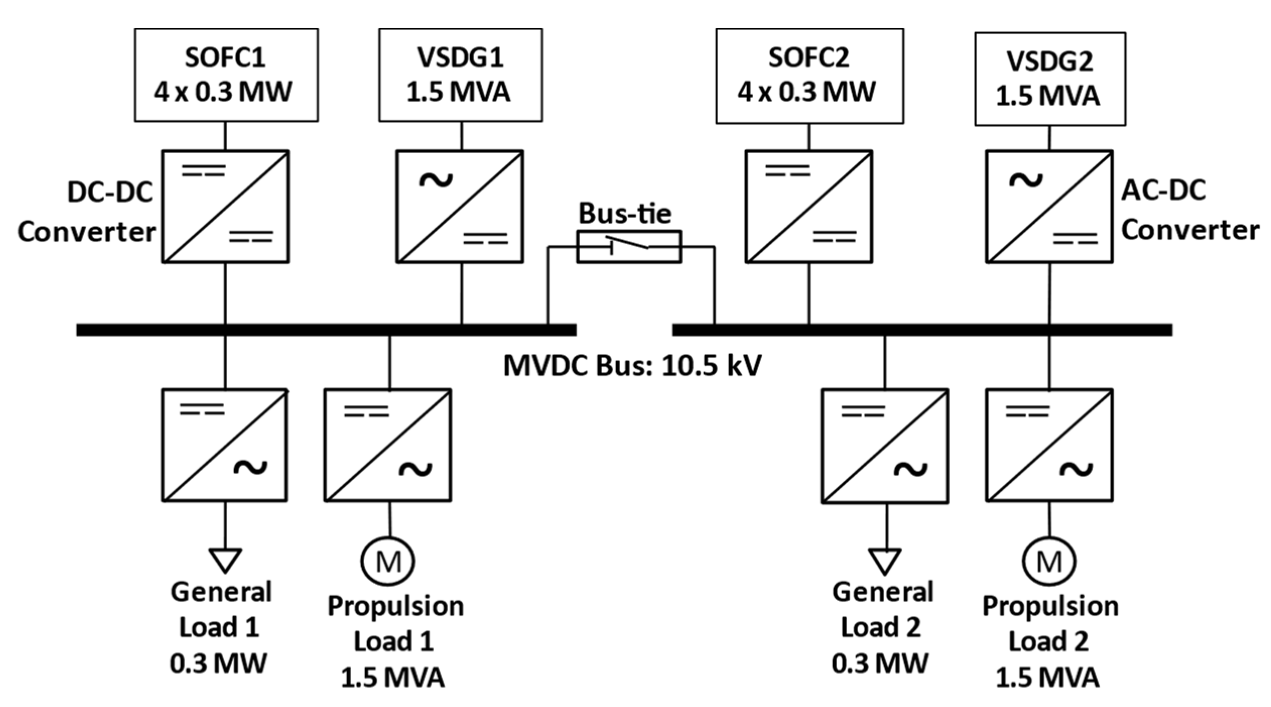
To address this limitation, conventional diesel generators remain necessary to provide backup power and fast transient responses. In recent years, variable-speed diesel generators (VSDGs) have gained attention as a complementary solution within hybrid marine power systems [6]. Unlike fixed-speed generators constrained by AC frequency requirements, VSDGs used in medium-voltage DC (MVDC) shipboard systems are decoupled from frequency, enabling flexible engine operation. This freedom allows the engine speed to be optimally controlled according to load conditions, resulting in improved fuel savings, especially under part-load operations [7]. Moreover, DC-coupled configurations offer advantages in terms of system efficiency, power density, and simplified control compared to traditional AC-based systems. An overview of the proposed hybrid SOFC/VSDG shipboard power architecture is presented in Figure 1. By integrating multiple generation units, the system can maintain continuous operation during component faults or scheduled maintenance, thereby improving overall reliability [8].
Given the complementary characteristics of SOFCs and VSDGs, there is a growing interest in developing coordinated control strategies to exploit their synergies. SOFCs can provide clean and efficient base-load power, while VSDGs can quickly respond to dynamic load changes. However, effectively coordinating these two sources requires a sophisticated control approach that balances system stability, dynamic performance, and fuel economy. Zahedi et al. [9] introduced the concept of variable speed operation in diesel generators, highlighting its potential to reduce fuel consumption and improve engine efficiency by decoupling the generator speed from electrical frequency, especially in DC systems, where frequency constraints are removed. However, the study lacked an explicit model of the diesel generator’s behavior under changing speed, meaning the dynamic implications of the engine speed variation on the power quality, system voltage, or load-following capability were not thoroughly investigated. Sun et al. [10] addressed the challenge of maintaining the fuel utilization factor of SOFCs within a safe operating range. A coordinated control scheme was developed, where the inverter follows the fuel controller in an AC microgrid environment. However, the study was limited to safety-oriented control and did not address the efficiency performance of SOFCs. Aziz et al. [11] proposed an advanced coordinated control strategy for hybrid systems, combining proton exchange membrane fuel cells (PEMFCs) and battery energy storage systems (BESSs) in shipboard applications. Their work introduced a combination of master–slave control and droop-based excitation, where the BESS acts as a rapid-response unit, while the fuel cell system is prioritized for long-term efficient generation. However, the strategy did not incorporate the dynamic speed control of diesel generators or model the specific fuel consumption curve of combustion sources, making it less comprehensive in addressing the unique fuel optimization challenges of SOFC-VSDG systems.
Although battery or supercapacitor energy storage systems are widely adopted in DC shipboard microgrids to buffer fast transients and mitigate DC bus voltage deviations, the deployment of dedicated storage often introduces considerable penalties in terms of cost, volume, weight, and system integration complexity, as well as additional safety and maintenance concerns in marine environments. Liu et al. [12] investigated an MVDC shipboard system required to withstand large pulsed power loads and proposed a distributed virtual resistive–capacitive droop scheme to coordinate power sharing among a gas-turbine genset and a hybrid energy storage system. However, their focus is primarily on transient voltage impact mitigation for large pulsed power loads and relies on energy-storage buffering. In contrast, the present study addresses a fundamentally different control objective by eliminating dedicated energy-storage and instead coordinating SOFCs and VSDGs through fuel-consumption-aware dispatch, targeting long-duration ship operating conditions rather than pulsed load mitigation. Similarly, Lin et al. [13] proposed a virtual admittance droop-based inertial coordination strategy for MVDC ships with hybrid energy storage, aiming to allocate transient power components across different frequency bands according to each device’s dynamic characteristics while also enabling SOC recovery without a secondary controller. Nevertheless, this line of work remains centered on transient compensation using hybrid energy storage and does not address fuel consumption-oriented coordination between SOFCs and VSDGs under ship operating profiles.
Most existing strategies are tested in AC microgrid settings or simplified simulation environments, with limited consideration for MVDC-based marine systems that present unique control challenges and opportunities. To address the complementary characteristics and limitations of SOFCs and diesel generators, we propose a coordinated control strategy for a hybrid marine power system based on an MVDC architecture. The primary objective is to enable efficient fuel usage for both the SOFCs and VSDGs. The proposed strategy aims to achieve an optimal balance between fuel consumption reduction and system performance by dynamically adjusting the operating points of each source based on system load conditions and fuel consumption profiles. The sub-objectives of this research include ensuring stable system operation, maintaining SOFC operational safety, and ultimately reducing overall emissions. The key contributions of this paper are summarized as follows:
  • The study establishes a hybrid SOFC/VSDG MVDC shipboard system model that captures the key energy conversion dynamics of the main subsystems, including the SOFC as the primary power source along with its auxiliary systems, VSDG, rectifier, and DC–DC converter, enabling performance analysis.
  • The study develops a VSDG/SOFC fuel consumption characteristic model to enable a comprehensive fuel-saving analysis under varying power conditions.
  • The study introduces a coordination scheme that allocates steady and transient power demands between multiple SOFCs and VSDGs to maintain MVDC bus stability while improving overall operating efficiency.
  • The study implements a supervisory upper-level dispatch controller that updates power references and online unit status based on the load condition and fuel characteristics, thereby reducing fuel consumption during typical ship operating profiles.
  • The study formulates an optimal operating framework that defines feasible and efficient operating scenarios for hybrid MVDC shipboard systems, considering practical constraints such as minimum generator loading and allowable speed ranges.
The remainder of this paper is structured as follows: Section 2 presents the component models used in this study. Section 3 describes the proposed hierarchical coordination and dispatch strategy. Section 4 reports the dynamic simulation results and discussion. Section 5 concludes the paper and outlines future work.

2. Power System Model Development

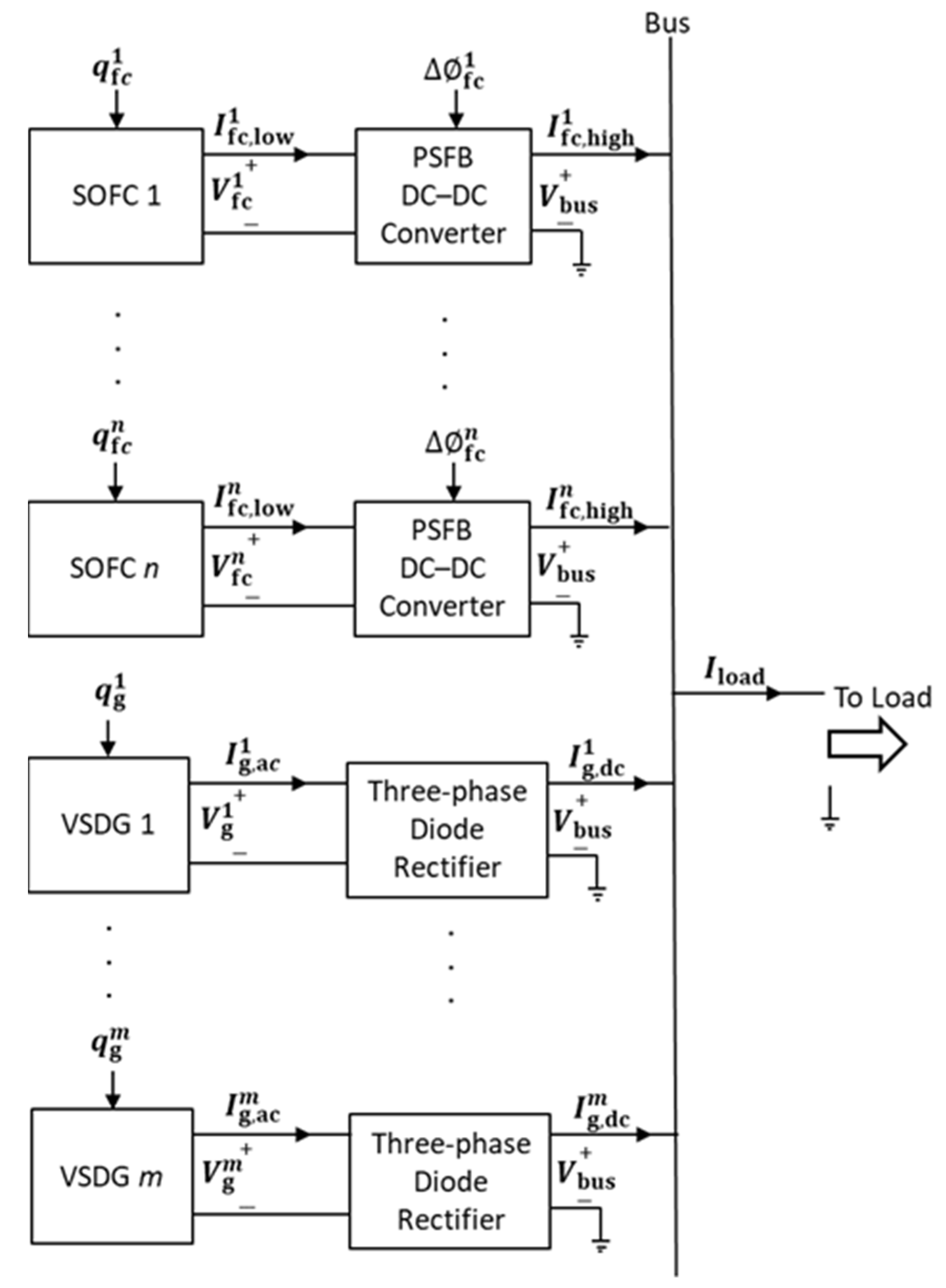
This section presents the modeling framework for the hybrid SOFC/VSDG MVDC shipboard power system. An overview of the architecture is shown in Figure 2. The system comprises an SOFC and a VSDG on the source side, whose outputs are combined on the common MVDC bus. The SOFC subsystem is connected through a phase-shifted full-bridge (PSFB) DC–DC converter to provide voltage boosting, whereas the VSDG subsystem is interfaced via a diode rectifier. The MVDC bus feeds the onboard loads, including a propulsion drive, as well as auxiliary and general loads.

2.1. SOFC System Model Development

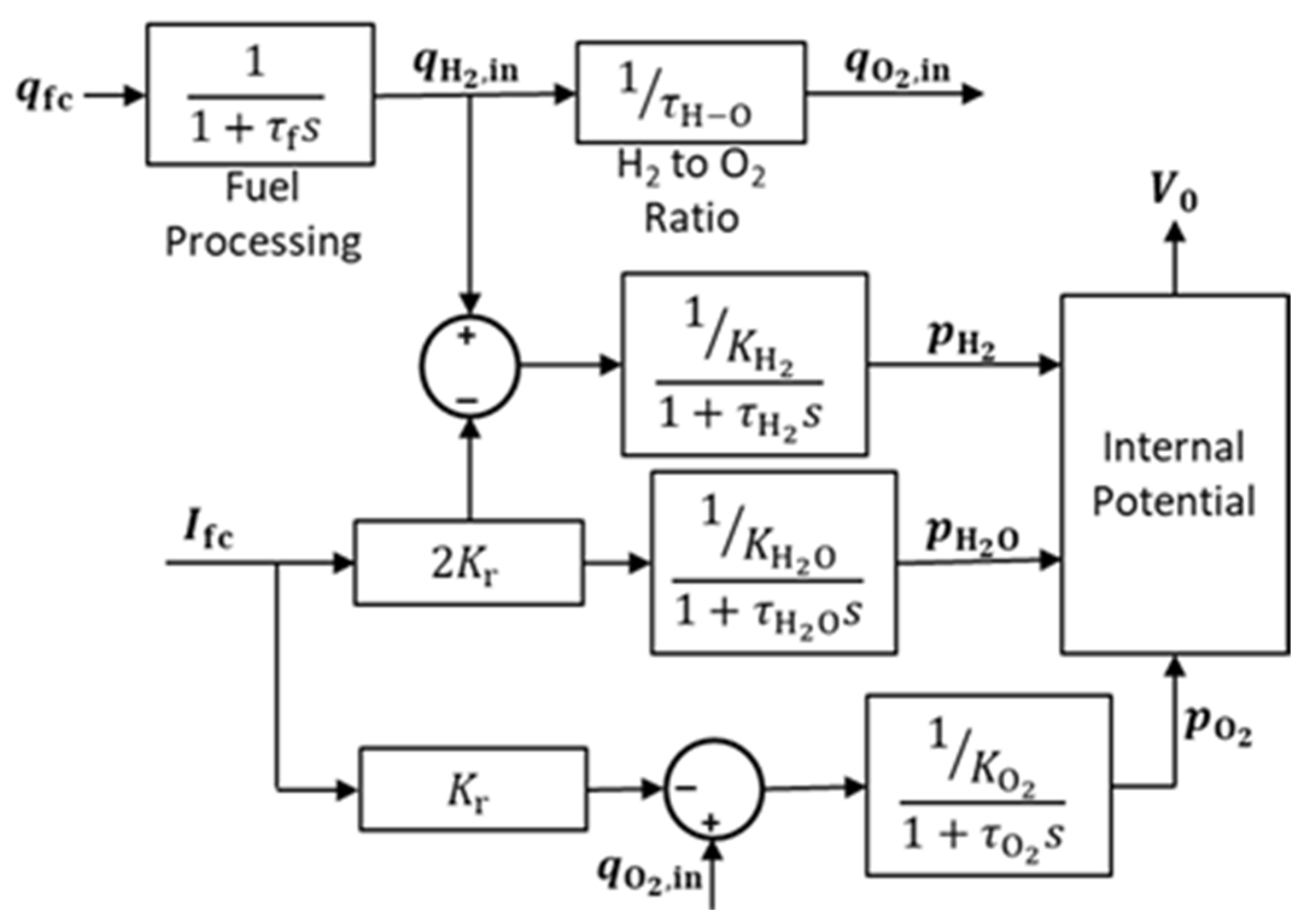
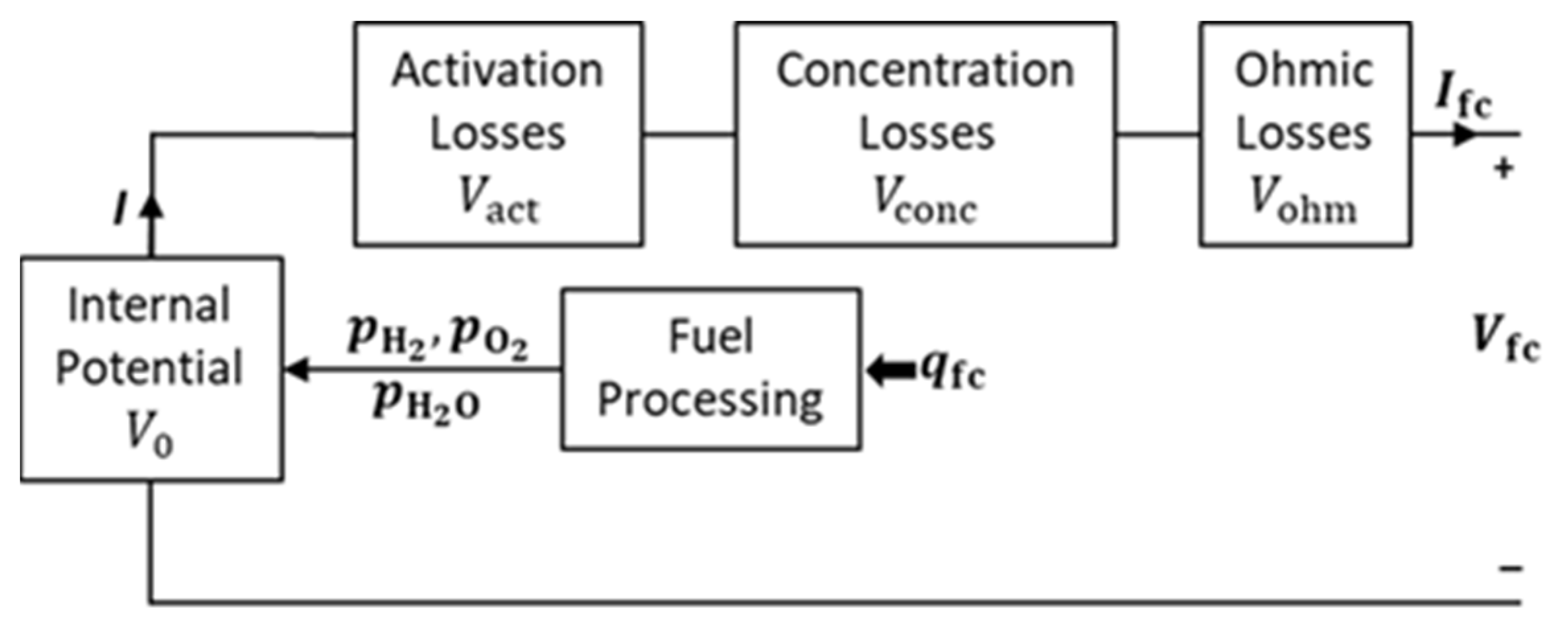
Figure 3 depicts the SOFC model as described in [10]. The output voltage of the SOFC, V f c , is defined by Equation (1):
V f c = V 0 V a c t V o h m V c o n c
The internal potential V 0 denotes the SOFC open-circuit voltage. During operation, the output voltage is reduced from the internal potential due to electrochemical polarization effects, including activation losses ( V a c t ), ohmic losses ( V o h m ), and concentration losses ( V c o n c ). The internal potential of an SOFC consisting of N 0 cells is expressed by Equation (2). All parameters are modeled dynamically in Figure 4. The absolute temperature T 0 is intentionally treated as a constant operating setpoint because the adopted lumped electrochemical model is used at the second-level time scale.
V 0 = N 0 E 0 + R 0 T 0 2 F 0 ln p H 2 p O 2 / 101,325 0.5 p H 2 O
The controlled variables are the flow rate of natural gas ( q f c ) and the output current of the SOFC ( I f c ). The internal states are flow rates of oxygen ( q O 2 , i n ) and hydrogen ( q H 2 , i n ) and partial pressures of hydrogen, oxygen, and steam, denoted as p H 2 , p O 2 , and p H 2 O , respectively. The activation, ohmic, and concentration losses are derived from Equations (3)–(5), respectively [14]. According to the VI characteristic curve of the SOFC, when the current is increased, the voltage will decrease because of the increasing voltage drop.
V a c t = α + β ln I f c
V o h m = r I f c
V c o n c = R 0 T 0 2 F 0 ln 1 I f c I L
The definitions and values of the parameters are presented in Table 1.
Table 1. Parameters of the SOFC model [10].
SymbolDefinitionValues
N 0 Number of cells in series700
E 0 Ideal standard potential1.18 V
R 0 Universal gas constant8.314 J mol−1 K−1
T 0 Absolute temperature1273 K
F 0 Faraday’s constant96,485 C mol−1
τ f Fuel processor time constant5 s
K r Reaction constant1.814 × 10−3 mol s−1 A−1
K H 2 Hydrogen valve molar constant8.32 × 10−6 mol s−1 Pa−1
K H 2 O Water valve molar constant2.77 × 10−6 mol s−1 Pa−1
K O 2 Oxygen valve molar constant2.49 × 10−5 mol s−1 Pa−1
τ H 2 Hydrogen flow response time26.1 s
τ H 2 O Water flow response time78.3 s
τ O 2 Oxygen flow response time2.91 s
τ H O Water flow response time1.145
r Ohmic loss0.126 Ω
α Tafel constant0.05
β Tafel slope0.11
I L Limiting current density800 A
Figure 3. Diagram of the SOFC model.
Applsci 16 01694 g003
Figure 4. Internal potential model of the SOFC.
Applsci 16 01694 g004
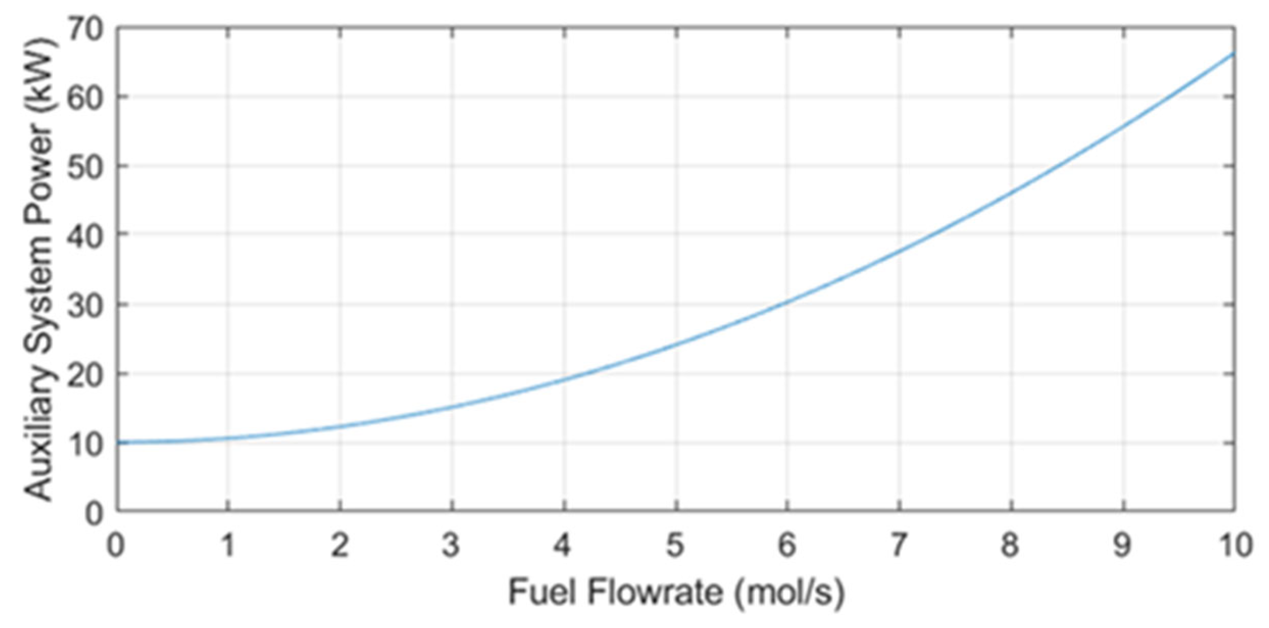
When analyzing the overall efficiency of an SOFC system, both the power generated by the SOFC and the energy consumed by its supporting components, commonly referred to as the auxiliary system, must be considered [15]. These components include fuel processors, air compressors, pumps, and thermal management units, which are necessary to maintain the SOFC operation. Figure 5 indicates that the auxiliary power consumption increases significantly with higher fuel flow rates. This increase is primarily due to the additional energy required to process, pump, and manage larger volumes of fuel under dynamic conditions. Therefore, any analysis of the SOFC performance must account for this parasitic load, especially during periods of high-power demand or transient operation.
The net output power of the SOFC system is the difference between the generated power of the fuel cell unit ( P f c ) and the power consumed by the auxiliary system ( P a u x ), as expressed in Equation (6):
P f c s = P f c P a u x
The efficiency of the SOFC system is not merely a function of the electrochemical performance of the fuel cell but also of how effectively the auxiliary loads are managed [16].
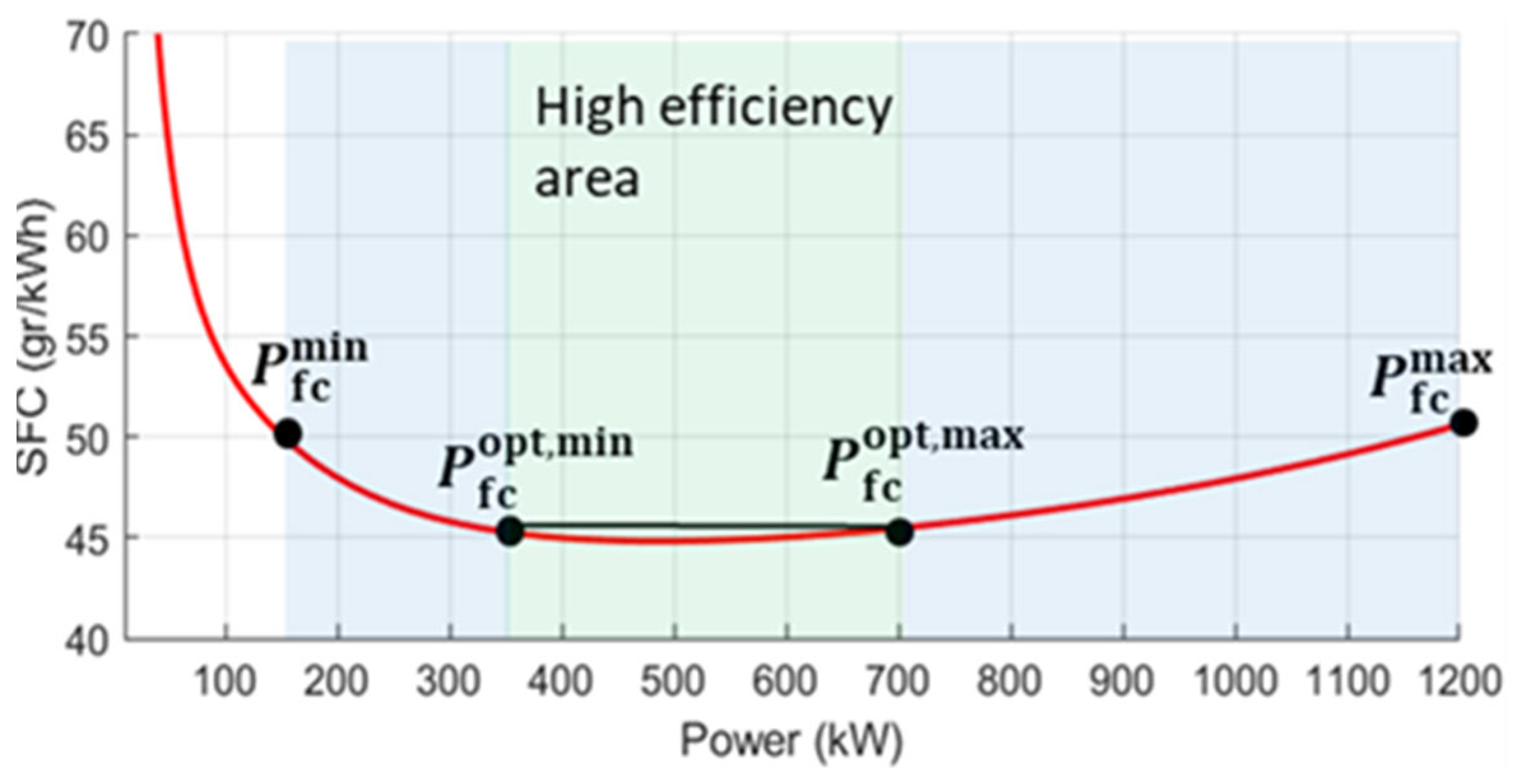
Figure 6 shows the results obtained when the SOFC was modeled with its auxiliary system. The results show that the auxiliary subsystem draws a non-negligible parasitic power, which becomes more pronounced at very low load levels. As the load increases, the specific fuel consumption (SFC) initially decreases, reaching an optimal range in which the system operates most efficiently. However, beyond this point, the SFC begins to increase again owing to the intrinsic electrochemical and thermal losses in the fuel cell stack. The resulting efficiency characteristic is consistent with previously reported trends in [17]. Based on the SFC profile, an optimal high-efficiency operating region for the SOFC is identified, defined by P f c o p t , m i n and P f c o p t , m a x . Operating the SOFC within this range ensures a balanced trade-off between the output power and fuel economy, maximizing the system’s overall energy conversion efficiency. If operation within the green zone is not feasible, the SOFC can operate within the blue zone, which is bounded by P f c m i n and P f c m a x . The lower operating limit P f c m i n is defined to prevent operation under excessively low-load conditions, where the SFC rises sharply, leading to significant degradation in fuel savings.
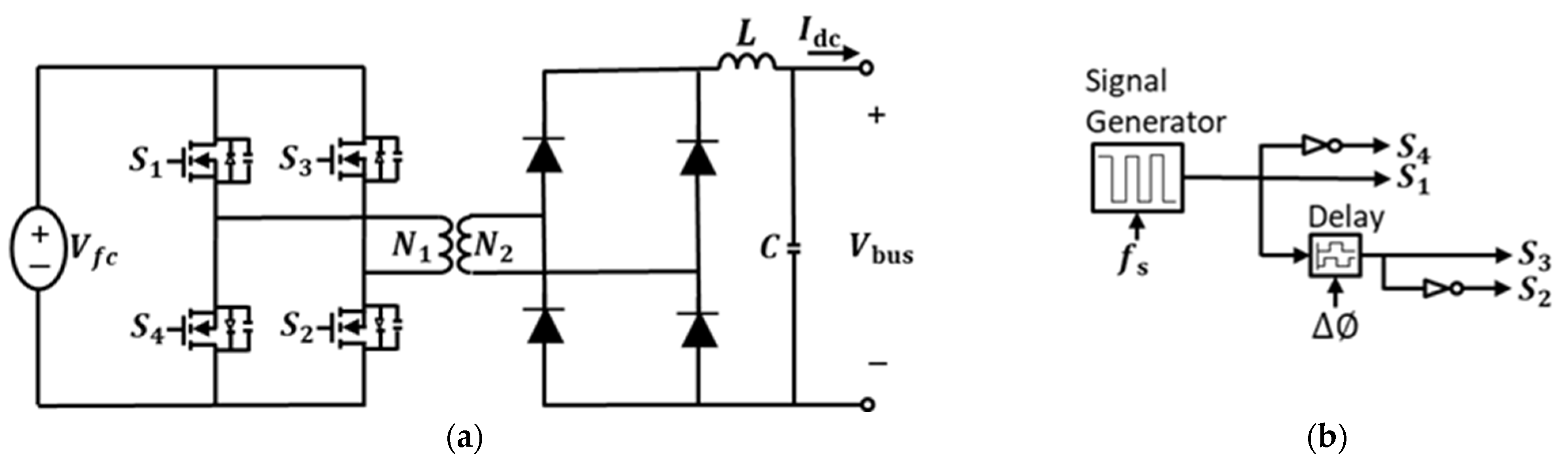
Because the SOFC naturally operates at lower voltage levels, a DC–DC converter is employed to elevate the output voltage, ensuring compatibility with the MVDC shipboard distribution system. The employed DC–DC converter topology is a PSFB converter consisting of a voltage-source converter, transformer, diode bridge, and LC filter [18]. PSFB converters are widely adopted in high-power isolated DC–DC applications, and their practical performance has been extensively studied. An improved PSFB converter was proposed to enhance soft-switching performance, especially at light loads and high currents [19]. The topology is suitable for SOFCs, whose characteristics offer only unidirectional power flow. The model of the SOFC with a DC–DC converter is shown in Figure 7a. The signals generated by the pulse-width modulator (PWM) are controlled using the mechanism illustrated in Figure 7b.
The principle of PSFB operation relies on introducing a phase shift between the gating signals of the two half-bridges, S 1 and S 4 with S 2 and S 3 . Instead of varying the pulse width directly, the effective duty cycle is controlled by delaying the turn-on of one leg with respect to the other. The phase-shift delay f c determines the overlap interval of the primary voltage waveform across the transformer and thus directly regulates the average output voltage of the converter and maintains the desired bus voltage. The relationship between the control variables and the DC bus voltage is expressed in Equations (7) and (8) [20].
D f c = 1 2 f c 2 π
V b u s = a V f c 2 D f c
where a is the ratio of the number of primary turns to that of secondary turns ( a = N 2 N 1 ). By regulating the phase shift f c in real time, the PSFB converter maintains the desired bus-voltage level across load variations and provides a controlled power transfer from the SOFC side to the MVDC bus.

2.2. VSDG System Model Development

A wound-rotor synchronous generator, in which the output electrical frequency is synchronized with the rotational speed of the machine, is employed. Meanwhile, the output voltage is controlled through the excitation system. In contrast to AC systems, DC systems are not constrained by electrical frequency, thereby allowing the engine to operate independently. This decoupling enables the optimal adjustment of the engine speed, leading to potential improvements in operational efficiency [21].
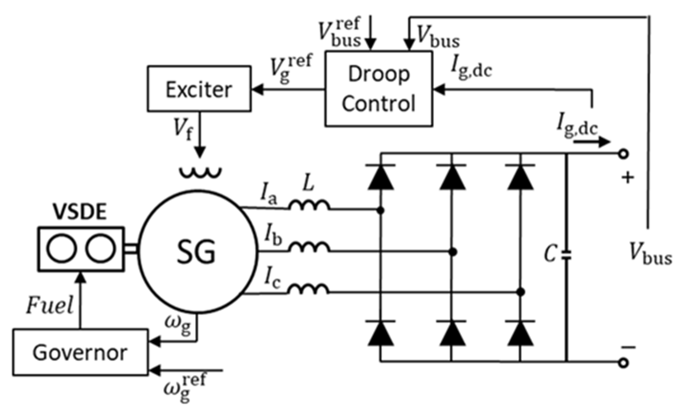
Figure 8 shows the model of a VSDG integrated with a three-phase diode rectifier. Diode rectifiers are commonly used for AC–DC conversion in shipboard power systems owing to their straightforward design, high reliability, and low cost [22]. However, owing to the lack of voltage control capability, voltage regulation is achieved by adjusting the excitation system of the diesel generator. A salient pole generator is employed in this system because it is well-suited for low-speed applications such as variable-speed diesel operations, offering distinct reactance values along the d- and q-axes. The DC-link filter components are sized such that the DC bus ripple is minimized. The output voltage, V b u s , is defined by Equation (9) [23].
V b u s = 3 2 π V g 6 f e L I g , d c
where V g is the line-to-line rms voltage from the AC output of the diesel generator, and f e is the electrical frequency of the AC side. Given that the DC side transmits only active power, the output power of the diode rectifier is equivalent to the active power delivered by the diesel generator. The active power and reactive power of the diesel generator output can be calculated using Equations (10) and (11).
P g = V b u s I g , d c = E a V g X d sin δ + V g 2 ( X d X q ) 2 X d X q sin 2 δ
Q g = E a V g X d cos δ V g 2 X q
where E a is the internally generated voltage of the generator; X d and X q are synchronous reactances in the d- and q-axes, respectively; and δ is the load angle between the internal and terminal voltages [24].
The internal voltage E a is obtained from Equation (12) and depends on the field voltage V f applied to the rotor field winding, which is regulated by the exciter. This voltage produces the field current that generates the magnetic flux, ultimately inducing the electromotive force in the stator. The value of K f represents a synchronous machine constant influenced by the number of turns, flux per pole, and saturation level. Therefore, based on these relationships, the output voltage of the diode rectifier can be controlled by adjusting the field voltage via the exciter.
E a = K f V f
The governor can control the frequency of the synchronous generator by adjusting the rotational speed of the engine due to the synchronization according to Equation (13). The rotational speed is set by regulating the fuel input to control the mechanical torque driving the engine. The mechanical torque T m required depends on the load conditions supplied by the generator, as expressed by Equation (14), and the relationship between the fuel input and mechanical torque is governed by the specific fuel consumption.
f e = p g ω g 4 π
P g = T m ω g
where p g is the number of poles in the synchronous generator.
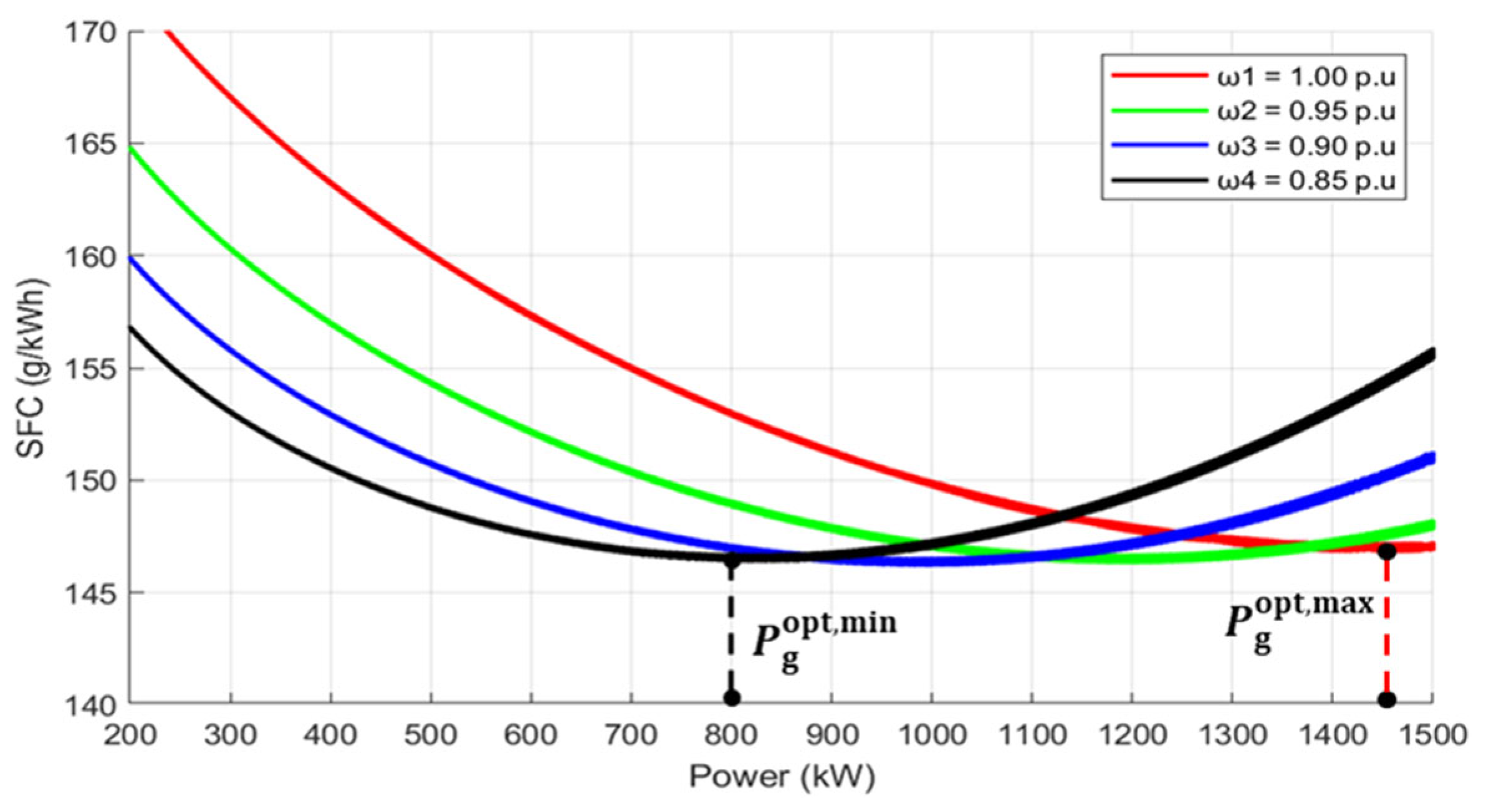
The SFC curve for the VSDG is shown in Figure 9. The modeled curve shape is validated against previous results [25]. The SFC curve can be obtained using the engine model based on Equation (15). All variables were calculated using the per-unit system. The definitions and values of the remaining parameters are presented in Table 2.
T m = q g ω g 1 + ρ T m a ω g 2 b ω g + c 2 + γ ω g ω g , o p t 2
The fuel savings of a VSDG can be enhanced by modifying the engine speed in relation to the engine load. In contrast to conventional fixed-speed generators, which are constrained to operate at a constant speed to maintain grid frequency, VSDGs offer significant advantages in terms of fuel savings. Fixed-speed generators tend to operate inefficiently under light-load conditions, consuming excessive fuel per unit of energy generated owing to suboptimal engine loading. In comparison, VSDGs can reduce the engine speed during low-load conditions, thereby minimizing mechanical losses and improving fuel economy. During high-load conditions, the engine speed is increased to efficiently supply the required power, enabling the VSDGs to continuously operate closer to their optimal fuel consumption point across varying load levels. Details on the parameters of the VSDG model are described in Appendix A.

3. Proposed Control Strategy

3.1. Control Strategy Development

In the design of a hybrid shipboard power system, a coordinated control strategy must be developed to exploit the complementary characteristics of different power sources. The strategy focuses on integrating SOFCs and VSDGs, each of which offers distinct advantages and limitations in terms of efficiency, responsiveness, and emissions. An intelligent control strategy must be designed to prioritize the operation of each source depending on its performance attributes to achieve both economic and environmental optimization. The comparison between an SOFC and a VSDG is shown in Table 3 [26].
The SOFC is prioritized as the primary power source owing to its superior fuel savings and environmental friendliness. It exhibits a low SFC, significantly outperforming the VSDG. Additionally, the fuel cost of SOFC systems is lower compared to that of diesel fuel used by VSDGs. Emissions from SOFCs are also considerably lower than those from VSDGs. These figures clearly justify the preferential use of SOFCs when steady power demand conditions prevail.
However, despite their environmental and economic benefits, SOFCs suffer from a slow dynamic response. This characteristic poses a significant challenge in systems with fluctuating or fast-changing load demands, such as those found in naval or high-performance marine vessels. To overcome this, a VSDG is introduced as a supporting power source owing to its fast ramp-rate capability. The VSDG can rapidly compensate for sudden power fluctuations that the SOFC cannot accommodate in real time. This enables the overall system to maintain stability and reliability during transient events without subjecting the SOFC to operational stress or inefficiency.
Based on these considerations, the control strategy is formulated to prioritize SOFC power contribution under steady or slowly changing load conditions, thereby leveraging its low fuel cost and minimal emissions. In contrast, the VSDG is selectively activated to handle fast dynamic load variations, ensuring a rapid response while minimizing its runtime and fuel consumption. This cooperative approach ensures that each source operates within its optimal performance envelope, with the SOFC covering the base load and the VSDG serving as a flexible auxiliary unit.

3.2. Coordinated Control Strategy

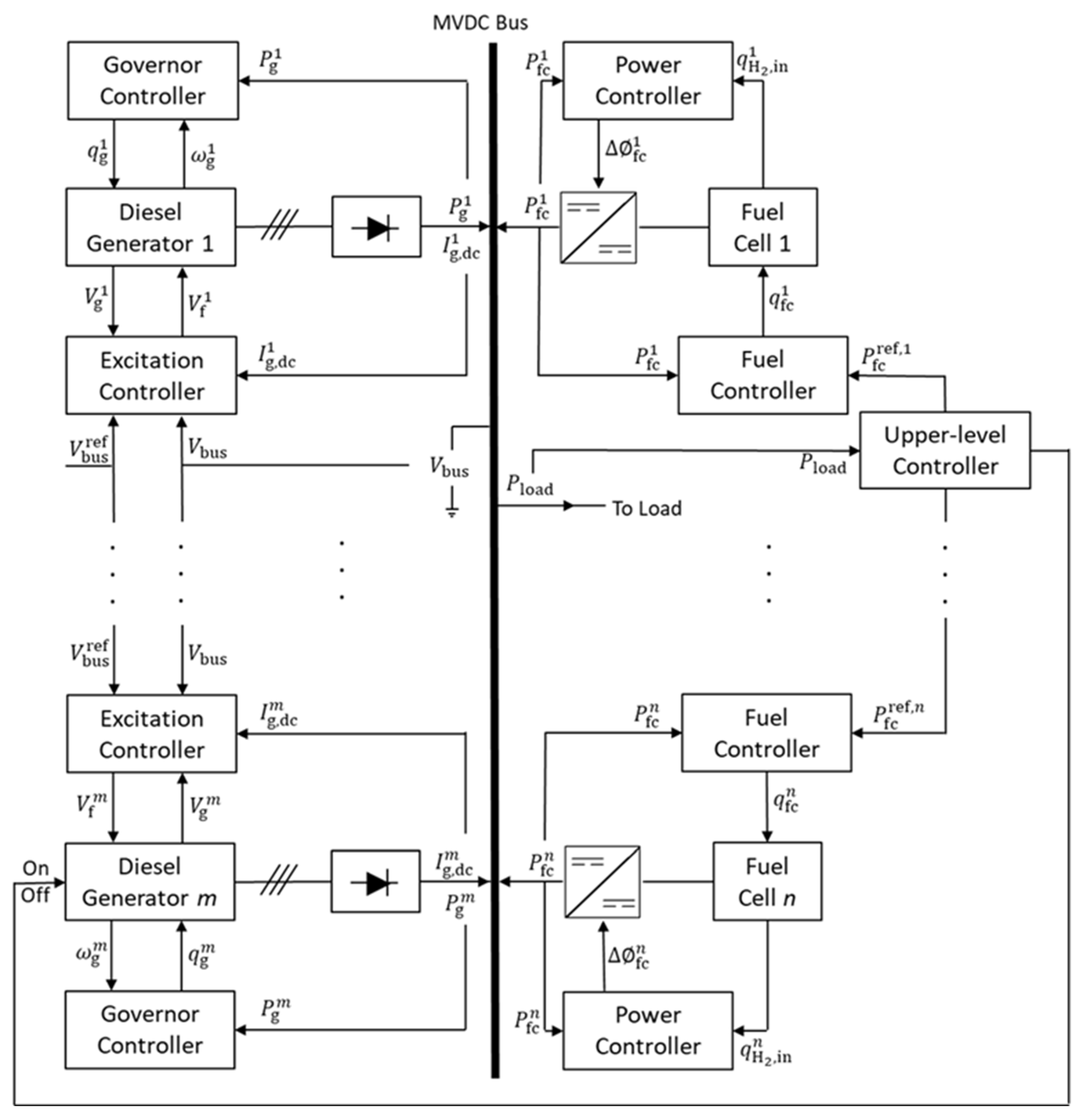
In this study, an integration control method combining master–slave coordination with droop-based regulation is proposed. The SOFC operates as the slave source, and its output power is controlled to keep the operating point within the identified high-efficiency range. In contrast, the VSDG is assigned as the master source and employs droop control to regulate the MVDC-bus voltage and share the required current among multiple VSDG units. At the supervisory level, an upper-layer controller determines the total SOFC reference power based on load conditions.
The overall coordinated control architecture for the hybrid SOFC/VSDG shipboard power system is presented in Figure 10, consistent with the system configuration introduced in Figure 2. By combining master–slave coordination and droop-based voltage sharing, the proposed control strategy achieves a balanced compromise between fuel savings, dynamic responsiveness, and operational reliability. The result is an optimal operating scenario for integrated shipboard power systems, aligning with both emission reduction goals and real-time power quality requirements.

3.2.1. VSDG Controller

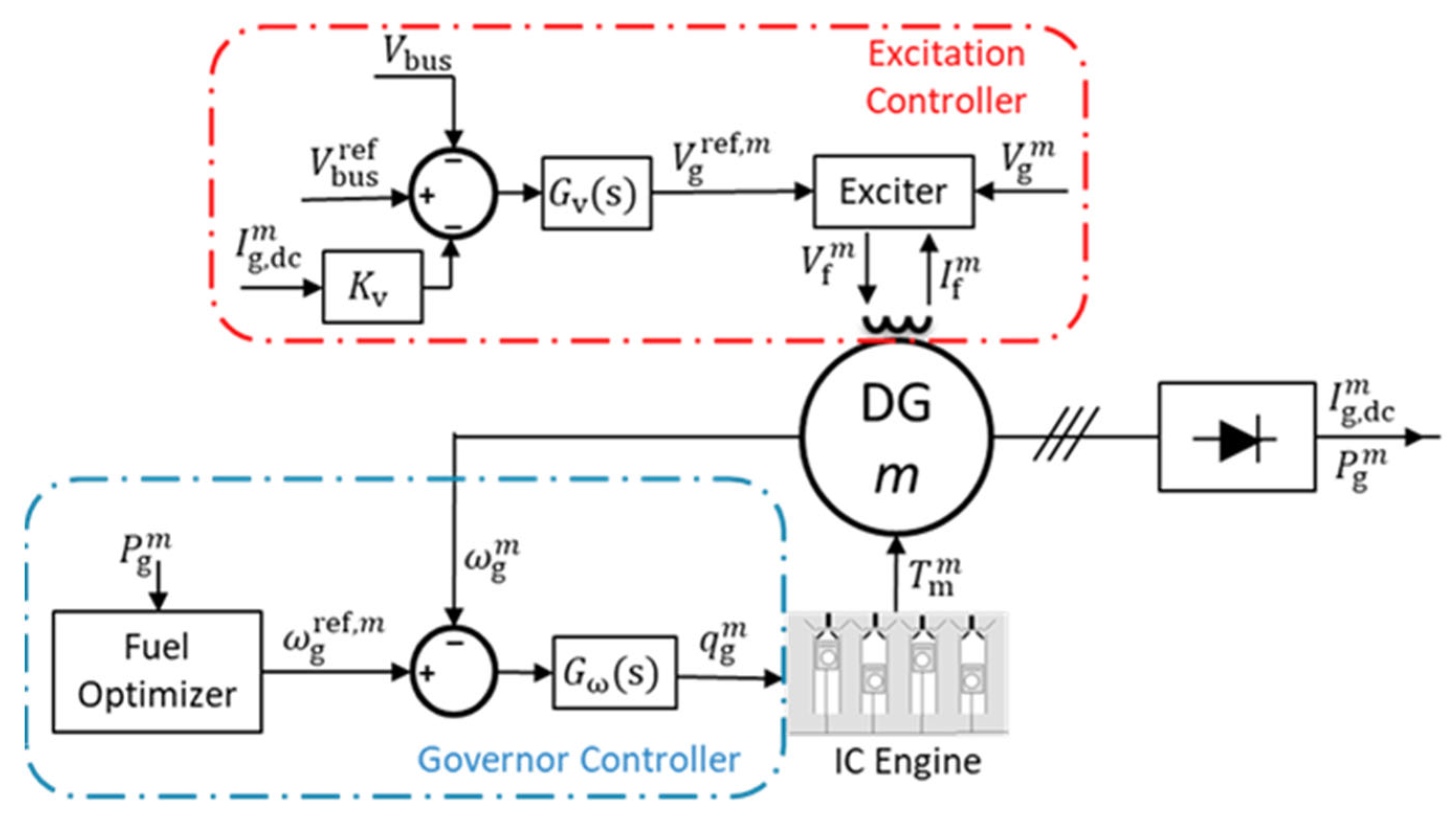
The block diagram of a VSDG controller is shown in Figure 11. The excitation controller manages the generator’s terminal voltage V g m by adjusting the exciter voltage V f m . This loop ensures proper voltage control at the generator terminal, particularly when interfacing with the MVDC bus. The reference voltage V g r e f , m is calculated based on the bus voltage reference V b u s r e f and is regulated through droop control. Droop control introduces a voltage offset proportional to the power loading of the generator, allowing proportional load sharing among multiple VSDGs connected to a common bus. This method improves system modularity and allows decentralized control without extensive communication between units.
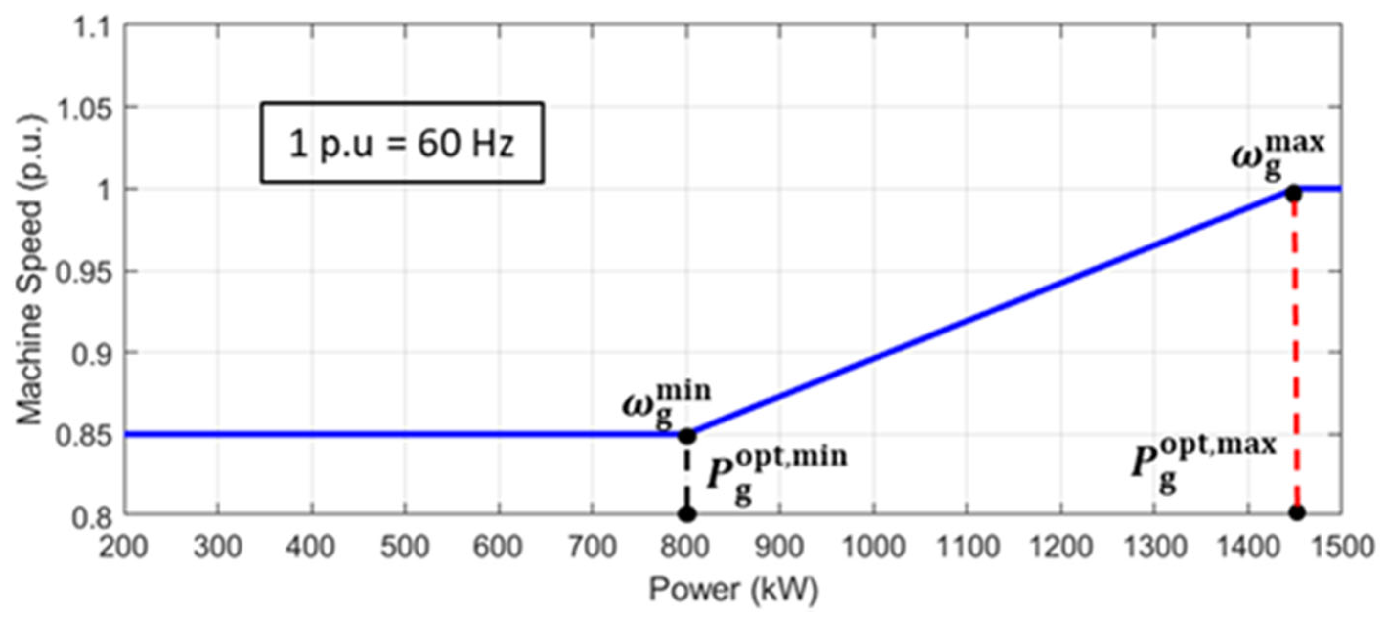
The governor controller governs the rotational speed of the diesel generator ω g m by modulating the fuel input to the internal combustion engine. The primary control objective is to minimize fuel consumption while satisfying the power demand. The speed reference ω g r e f , m is determined by a fuel optimizer, which maps real-time power demand P g m to the speed that yields the SFC. This mapping is based on a pre-identified SFC curve of the diesel engine under various load and speed combinations, as shown in Figure 9, using Equation (16). Figure 12 shows the P−ω curve of the proposed control method. Once the reference is generated, a PI controller is used to track by regulating fuel input to the engine, ensuring both stability and fast response to load variations.
ω g r e f , m = ω g m i n ω g m i n + P g m P g o p t , m i n ω g m a x ω g m i n P g o p t , m a x P g o p t , m i n   ω g m a x , where   P g m P g o p t , m i n                                           , where   P g o p t , m i n P g m P g o p t , m a x ,   where   P g m P g o p t , m a x                          

3.2.2. SOFC Controller

One of the key performance metrics for the SOFC is the fuel utilization factor, defined as the ratio of the reacted hydrogen flow rate to the input hydrogen flow rate from Equation (17) [10].
u f c = q H 2 , i n q H 2 , o u t q H 2 , i n = q H 2 , r q H 2 , i n = 2 K r I f c q H 2 , i n
where q H 2 , r is the reacted hydrogen flow rate. To ensure stable operation, the utilization factor should be maintained within the recommended range of 0.7–0.9. Operating beyond the upper limit ( u f c > 0.9) poses a critical risk as it may cause a significant drop in the output voltage and power, potentially destabilizing the fuel cell system. Conversely, operating below the lower limit ( u f c < 0.7) may result in excessive voltage and reduced power output, indicating inefficient fuel usage.
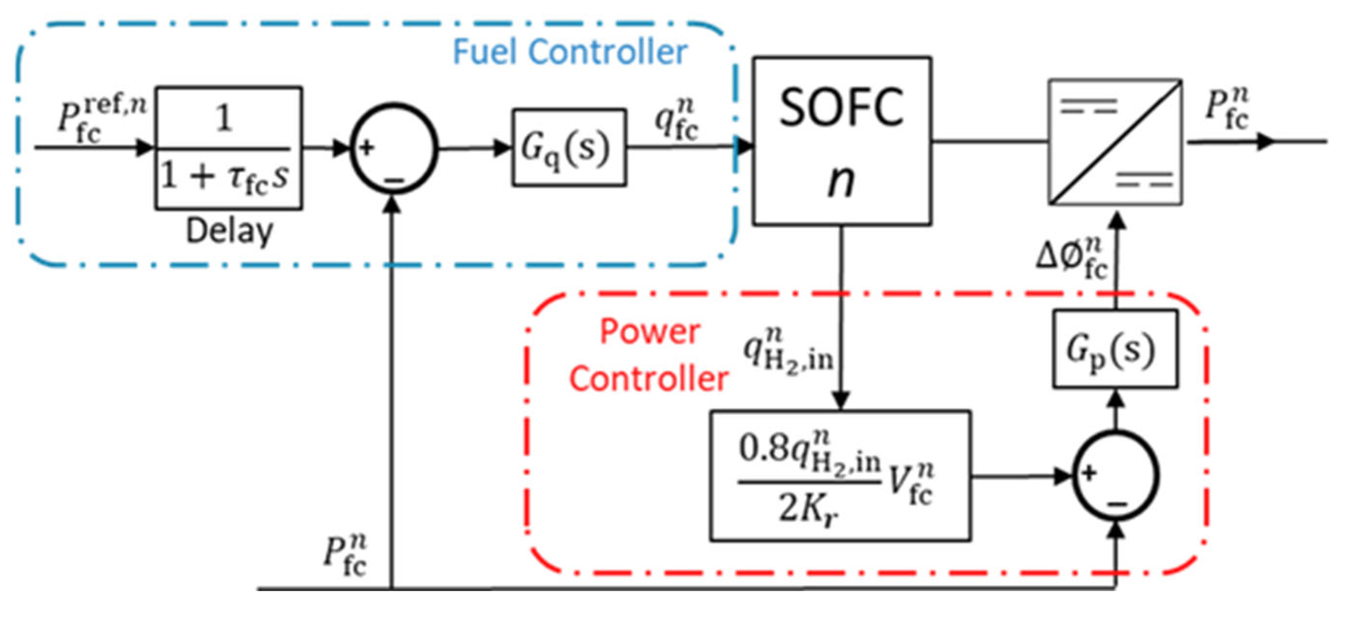
To maintain the operational efficiency and safety of the SOFC in the hybrid shipboard power system, a converter is introduced. The controller manages both the fuel flow rate and output power of the SOFC to ensure optimal performance, with a key objective of maintaining a constant fuel utilization factor. The utilization factor is fixed at 0.8, which is considered a conservative and safe value, preventing over-utilization or starvation conditions that could degrade the fuel cell stack.
The block diagram of an SOFC controller is shown in Figure 13. The SOFC controller consists of two key control subsystems, namely a fuel controller and a power controller, which operate in coordination with a PSFB DC–DC converter. The fuel controller receives the reference power P f c r e f , n from an upper-level controller. This reference signal is then processed by a PI controller to generate a command for the fuel flow rate. This command ensures that sufficient fuel is supplied to meet the expected SOFC power output while keeping the fuel utilization within a predefined range.
Meanwhile, the power controller governs the actual output power of the SOFC by controlling the phase-shift delay f c of a DC–DC converter. This converter adjusts the voltage level of the SOFC output to match that of the MVDC system while indirectly controlling the output current and ultimately, the real power output. The controller calculates the required output by referencing the utilization factor equation.

3.2.3. Upper-Level Controller

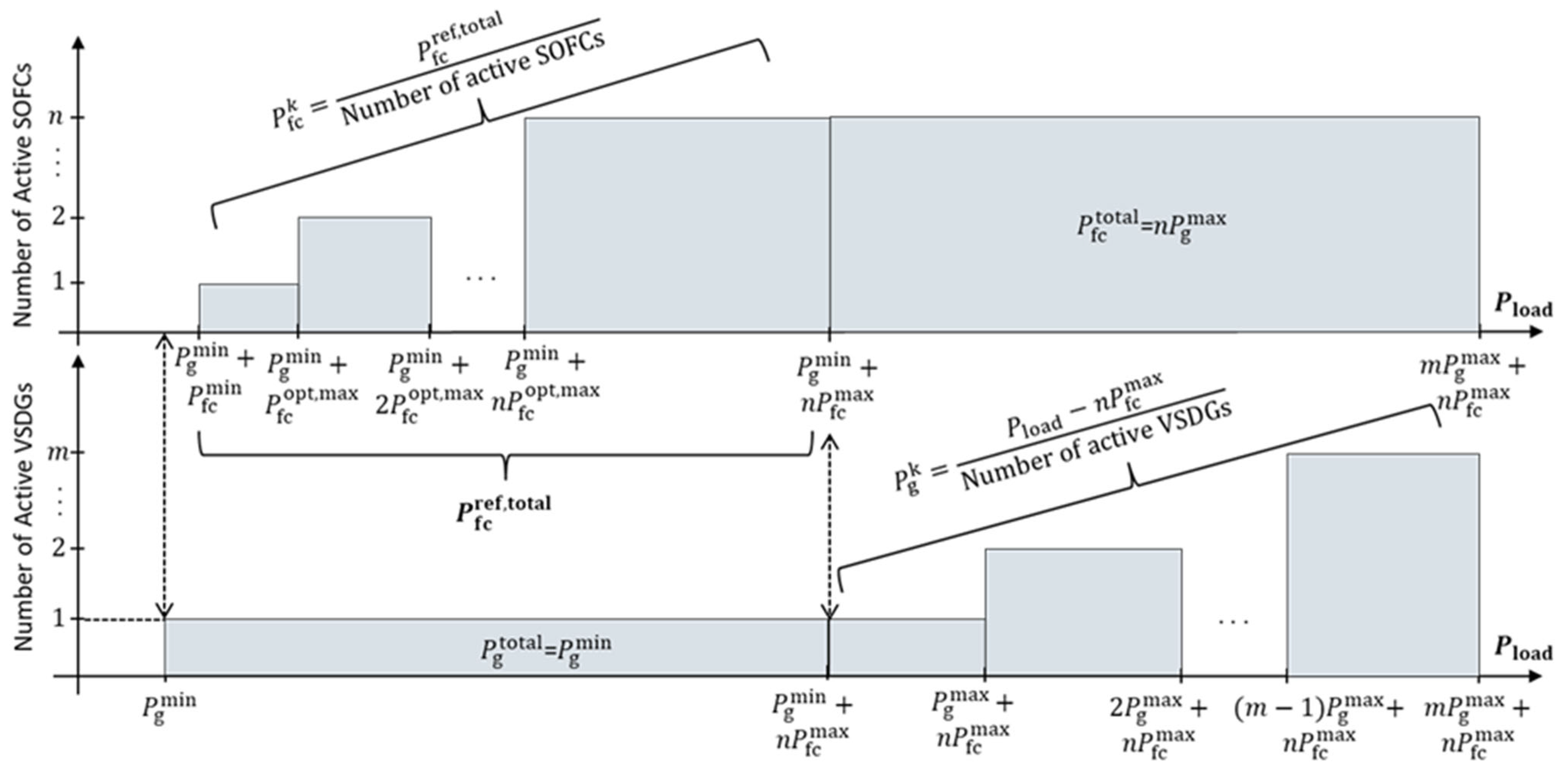
Figure 14 presents the proposed operational concept for optimal shipboard system scheduling. The upper-level controller determines the number of online SOFC units so that each operating SOFC remains within the high-efficiency region identified in Figure 6. One VSDG is also controlled to operate at its minimum output P g m i n while the SOFC has not yet reached its maximum capacity P f c m a x . After all SOFCs reach their maximum point, the number of operating VSDGs is controlled according to the required load conditions.
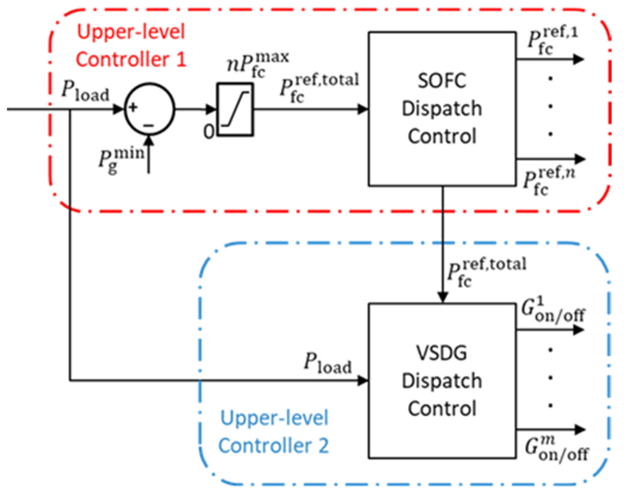
An upper-level controller is developed based on the proposed conceptual framework, as illustrated in Figure 15. Upper-level controller 1 is used for dispatch control of the SOFC, while upper-level controller 2 is used for dispatch control of the VSDG. In the upper-level controller 1, the controller first establishes a reference power P f c r e f , t o t a l for the collective SOFC output. This value is determined by subtracting the minimum power output of the VSDG from the total system load P l o a d . By assigning only the residual power to the SOFCs, the system ensures that VSDG handles transients and base-load stability, while the SOFCs are leveraged for sustained, high-efficiency operation. This strategy also ensures that the SOFCs are not overburdened, which could push them into low-efficiency or potentially unsafe operational states.
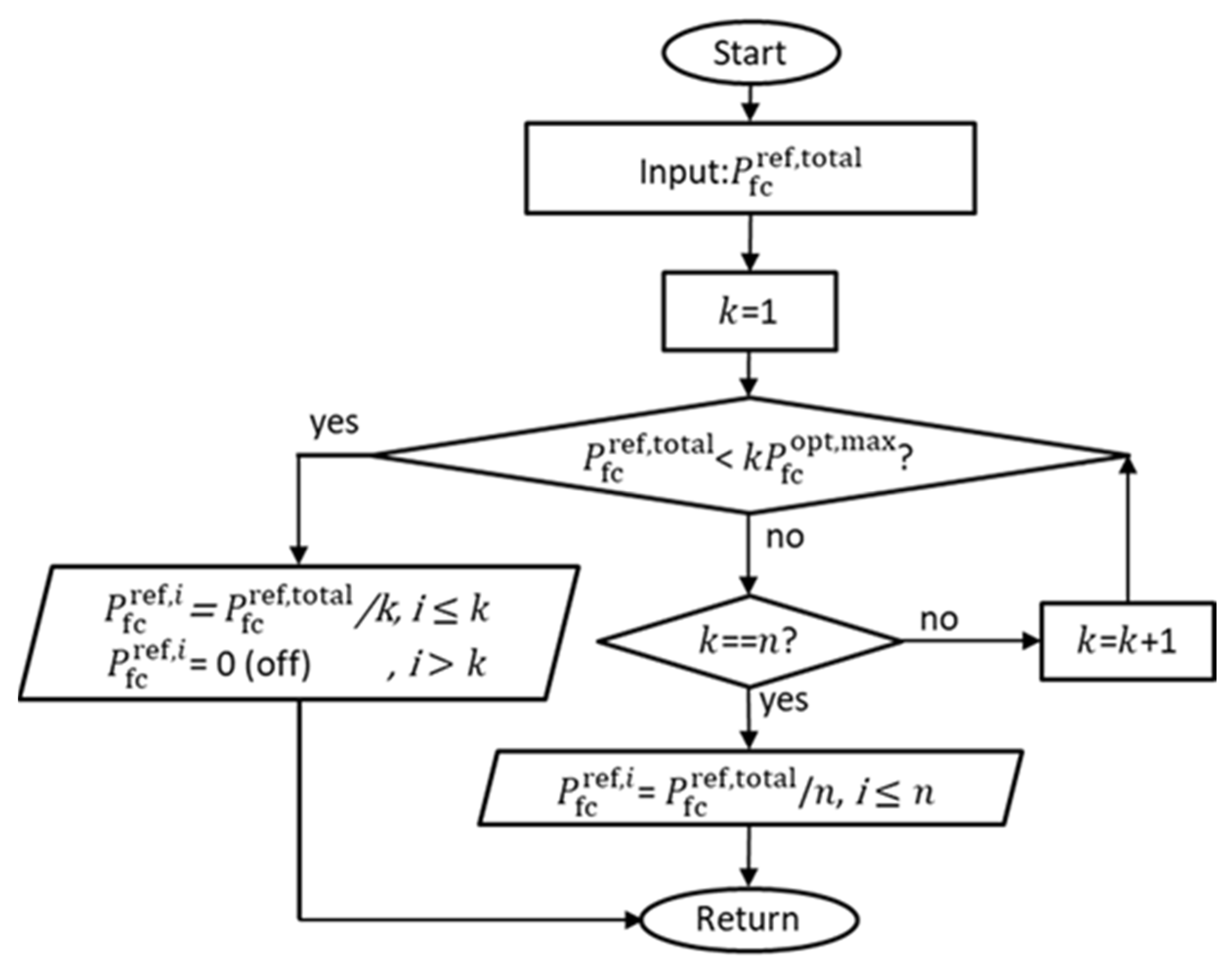
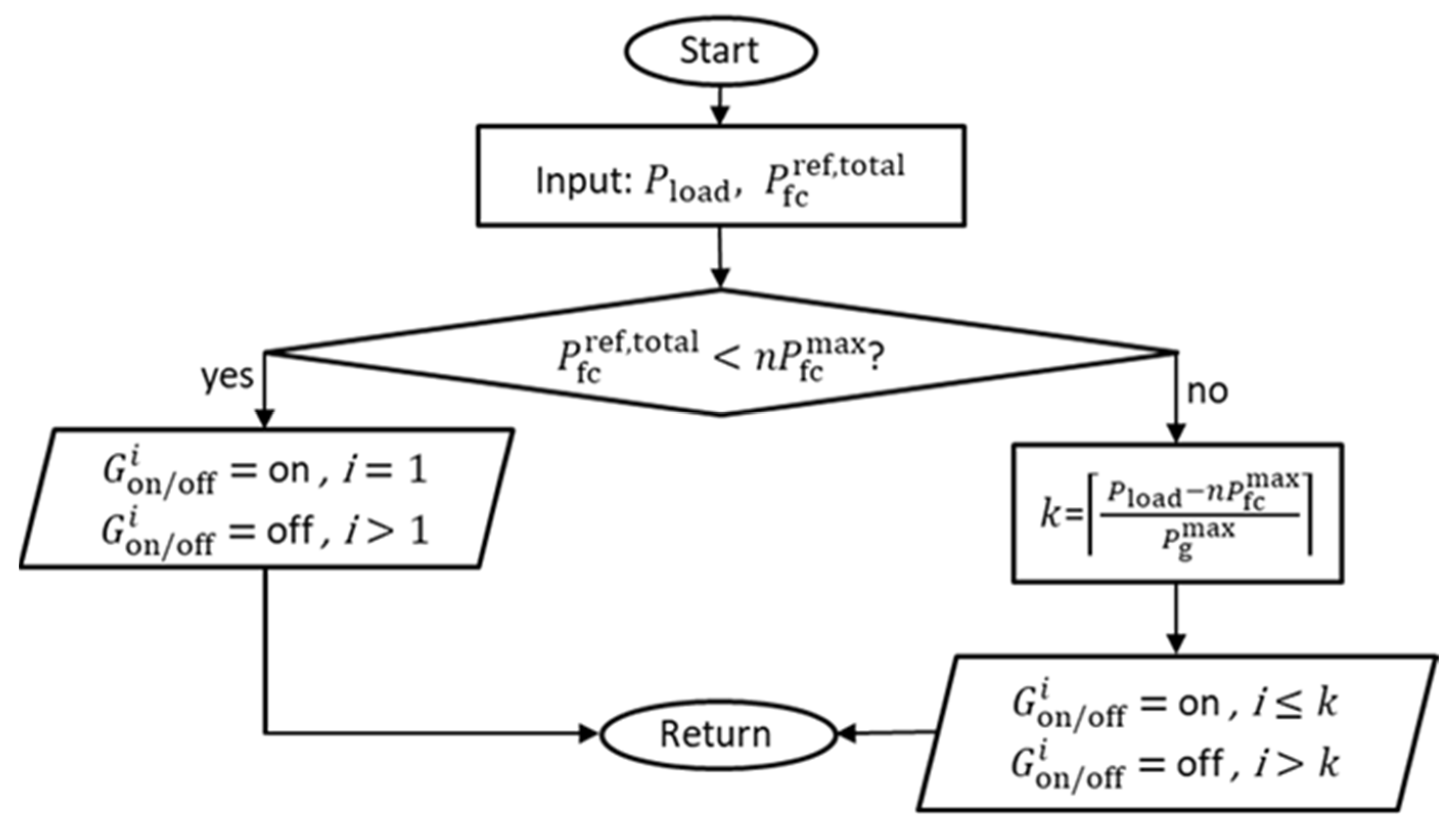
Next, the upper-level controller 1 performs SOFC dispatch control, which involves determining how many SOFC units should be active and how to distribute P f c r e f , t o t a l among them. The dispatch logic is designed to activate only the required minimum number of SOFCs, such that each unit operates within its optimal power range, as derived from the SFC curve of the SOFC. This approach is illustrated in the flowchart presented in Figure 16. The final stage of the controller involves sending individual power references P f c r e f , n to each SOFC, which are then handled by their respective local controllers.
In the VSDG dispatch control, the operational status of each VSDG is governed by the flowchart presented in Figure 17. Each VSDG is activated as needed to satisfy the load demand while ensuring that its rated capacity is not exceeded. With the implementation of droop control, all active VSDGs share the load proportionally, thereby delivering equal output power. Prior to all SOFCs reaching their maximum power point, only a single VSDG operates at its minimum output to maintain voltage stability. This modular structure enables the system to adapt dynamically to changing load conditions without compromising efficiency. Furthermore, by limiting the VSDG operation to only the minimum required output, the overall system fuel consumption and environmental footprint are minimized.
The upper-level controller implements power dispatch and unit commitment logic. Although dispatch is often associated with slow scheduling, the setpoint computation and communication are not inherently slow and can be updated on the order of tens of milliseconds in typical supervisory control networks. In practice, however, slow observable changes may arise because shipboard power management systems intentionally apply start/stop delay logic to prevent unnecessary generator cycling, and because the physical dynamics of the sources limit ramp rates.

4. Dynamic Simulation Results

4.1. Simulation Configuration

To assess the proposed coordinated control strategy, a time-domain simulation model of the shipboard MVDC system was implemented based on the configuration shown in Figure 1. The test system includes two SOFC units and two VSDGs, using the same ratings and parameter sets as the component models introduced in Section 2. All simulations were carried out using Power System Computer-Aided Design/Electromagnetic Transients, including DC (PSCAD/EMTDC), and detailed simulation parameters are summarized in Table 4.
The simulation cases were divided into two groups: low- and high-load conditions. Each case compared various scenarios, as shown in Table 5. When evaluating the fuel savings of the proposed hybrid control strategy, system behavior must be analyzed under alternative scenarios where key coordination mechanisms are not considered. First, if the variable speed control of the diesel generator was not implemented, the DGs would operate consistently at full speed (1.0 p.u) regardless of the load condition. Second, in the absence of SOFC dispatch control, the system would distribute power equally among all SOFC units, regardless of the total load. Third, if SOFCs were not prioritized over DGs, the control system might have allowed DGs to meet load demands first, activating SOFCs only after DGs reached their capacity limits.
To demonstrate the effectiveness of the proposed coordinated control, comparative simulation experiments were conducted using five control strategies under identical plant models and load profiles. Scenario 1 is the proposed method, while other scenarios serve as benchmark controllers obtained by disabling one or more key coordination components. This benchmarking provides a fair comparison by isolating the contribution of each control mechanism.

4.2. Results and Analysis Under Low-Load Conditions (Case 1)

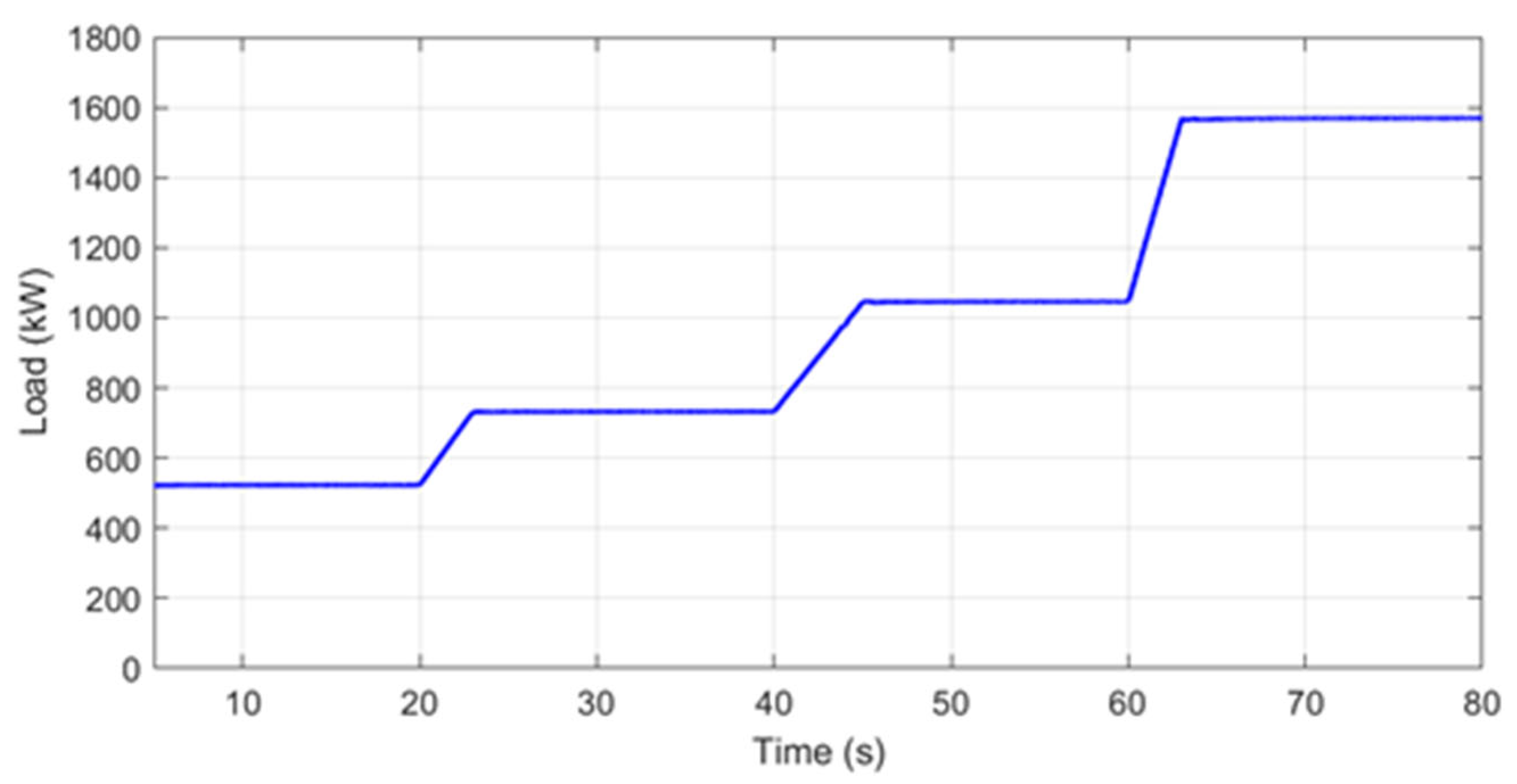
In Case 1, the overall system performance was evaluated under low-load conditions, where the load was under 50% of full load (<1.8 MW). The load scenario for the dynamic simulation of Case 1 is shown in Figure 18. The simulation was conducted in 80 s.
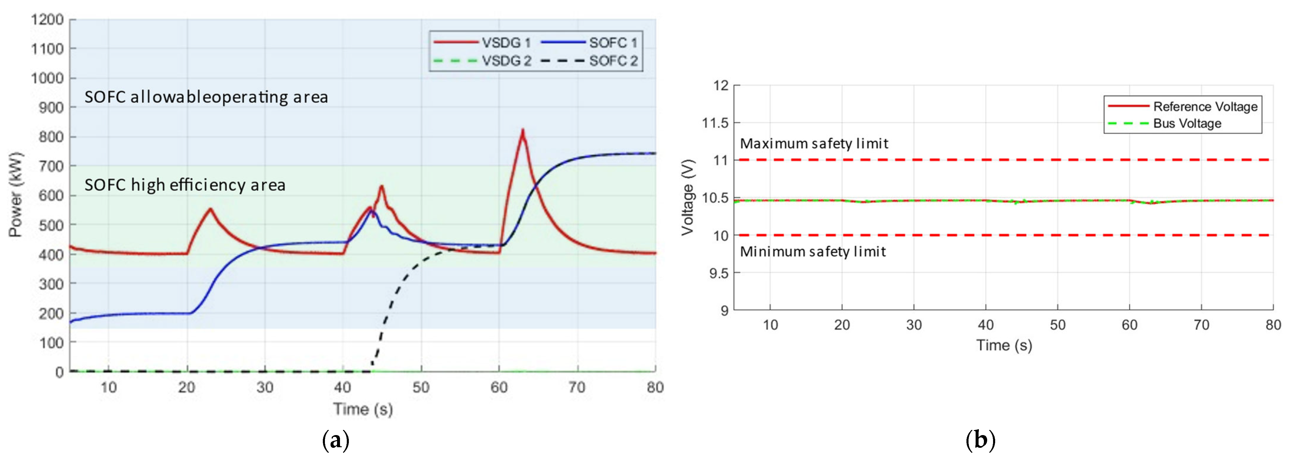
As depicted in the power generation simulation results in Figure 19a, the load began at a low value, during which one VSDG was initially active to provide immediate power. Because SOFCs have a limited ramp rate, they respond slowly to load transients. However, the VSDG, with a high ramp capability, compensated for the power gap caused by the delayed response of the SOFCs. This immediate contribution ensured that the system avoids under-voltage conditions during transitional states. Over time, as the SOFC output ramped up, the control strategy transitioned the power responsibility from VSDG to SOFCs. By approximately 60 s, the SOFCs took over most of the load and stabilized within their high-efficiency operating zone, as intended by the SOFC dispatch control. This outcome confirmed the advantage of the proposed upper-level controller that intelligently limited the number of active SOFC units and assigned power references such that each operated within its high-efficiency area.
The voltage profile shown in Figure 19b illustrates the robustness of the system in maintaining DC bus voltage stability. Despite changes in power source contributions, the bus voltage remained consistently within the predefined safety margins, hovering closely around the reference voltage of 10.5 kV, which is the rated DC voltage. This validates the effectiveness of the droop-based excitation control on the VSDG, which adjusted the generator’s excitation voltage in real-time to regulate the bus voltage even under dynamic loading conditions. The coordination between the fast-reacting VSDG and slow-ramping SOFCs ensured that the voltage deviations were minimal and within the acceptable range.
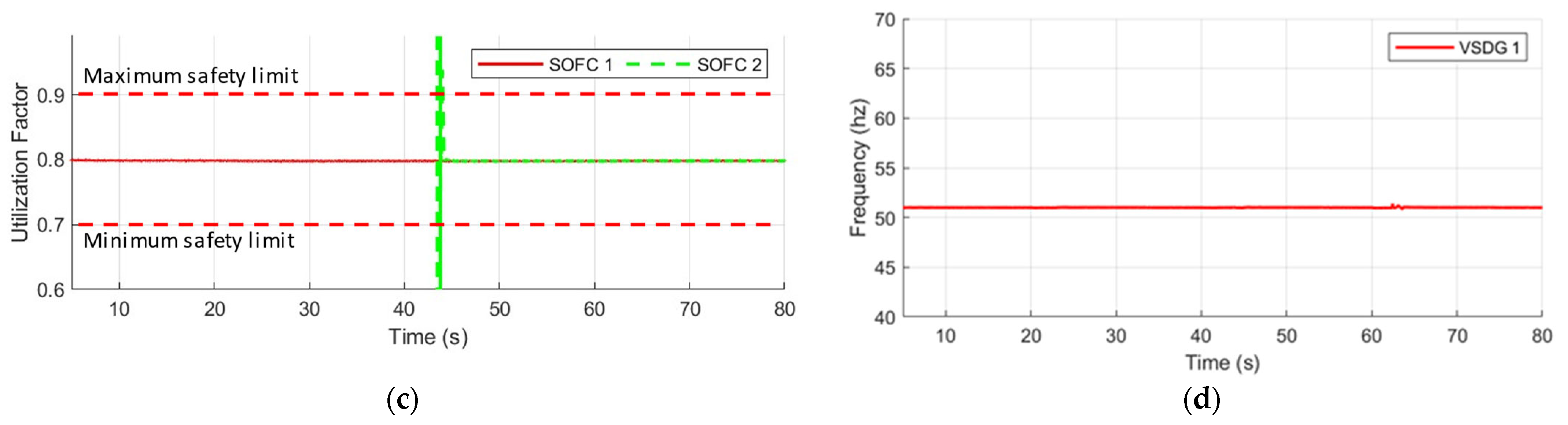
Figure 19c illustrates the dynamic behavior of the fuel utilization factor for two SOFC units over time. The target value of 0.8 was enforced through the coordinated control strategy, which regulated fuel flow according to power output in real time. As observed in the simulation, both SOFCs maintained their utilization factor at approximately 0.8 throughout the entire operating period, well within the desired safety range bounded by 0.7 and 0.9. This demonstrates the effectiveness of the fuel controller in maintaining a stable hydrogen-to-power conversion ratio, even during transitions in SOFC activation or ramping. The simulation confirms that only one SOFC was active initially, with the second unit operating later, corresponding to a step increase in load around 40 s. Despite this transition, the active units continued to operate near their nominal utilization target without overshooting the critical thresholds. It should be noted that the brief excursion of the utilization factor beyond the safe range at the moment of SOFC activation is attributed to the definition of the fuel utilization factor itself. When a fuel cell is initially off, both current and hydrogen flow are zero. During startup, the fuel cell momentarily approaches zero, which results in a transiently large calculated value. However, this anomaly occurs only for a fraction of a second and under negligible power levels and therefore does not pose any operational risk to the system.
The dynamic response of the generator frequency is shown in Figure 19d. The VSDG frequency was consistently maintained at 51 Hz, which corresponded to the minimum operating speed of the diesel engine within the allowed range. This reflected the outcome of the proposed variable speed optimization, where the generator operates at reduced speed under light load to minimize the SFC. Because the SOFCs could supply most of the power demand under low-load conditions, the VSDG was only required to maintain base-level support and voltage regulation.
To further assess the effectiveness of the proposed coordinated control strategy, a comparative fuel consumption analysis was performed under low-load conditions for five scenarios. As shown in the simulation results in Table 6, Scenario 1, which implements all three control strategies, yielded the lowest total fuel cost at $2.360, with the SOFC fuel consumption of 521 g and DG fuel consumption of 1425 g. This outcome highlights the benefit of coordinated power sharing, where the SOFC handles the base load efficiently while the VSDG operates at reduced speed, minimizing its fuel demand.
By contrast, prioritizing the VSDG over the SOFC as the main source increased the fuel cost by 70.4%. These scenarios clearly demonstrate that prioritizing VSDGs over SOFCs in low-load conditions is less efficient, as diesel fuel is more expensive and DGs consume more fuel per kWh than SOFCs. Even in Scenario 2, where only the SOFC dispatch control was disabled while retaining prioritization and speed control, a slight increase of 0.7% in total costs was observed, showing that the SOFC dispatch control further enhanced fuel savings by ensuring that each unit operates in its high-efficiency area. These comparative experiments confirm that the proposed strategy provides the best fuel-economy outcome under identical conditions. The largest degradation occurs when SOFC dispatch and prioritization and DG speed optimization are removed, indicating that fuel-optimal dispatch and variable-speed operation are decisive contributors to fuel cost reduction in low-load profiles.
The overall trend confirms that the proposed control strategy not only reduces the operational cost but also optimally leverages the strengths of both power sources. The SOFC operated in its high-efficiency area, and the VSDG’s load was kept minimal and speed-optimized. This synergy ensured that both energy and cost efficiency were maximized, validating the control strategy as a superior solution for shipboard power systems operating under varying load conditions.

4.3. Results and Analysis Under High-Load Conditions (Case 2)

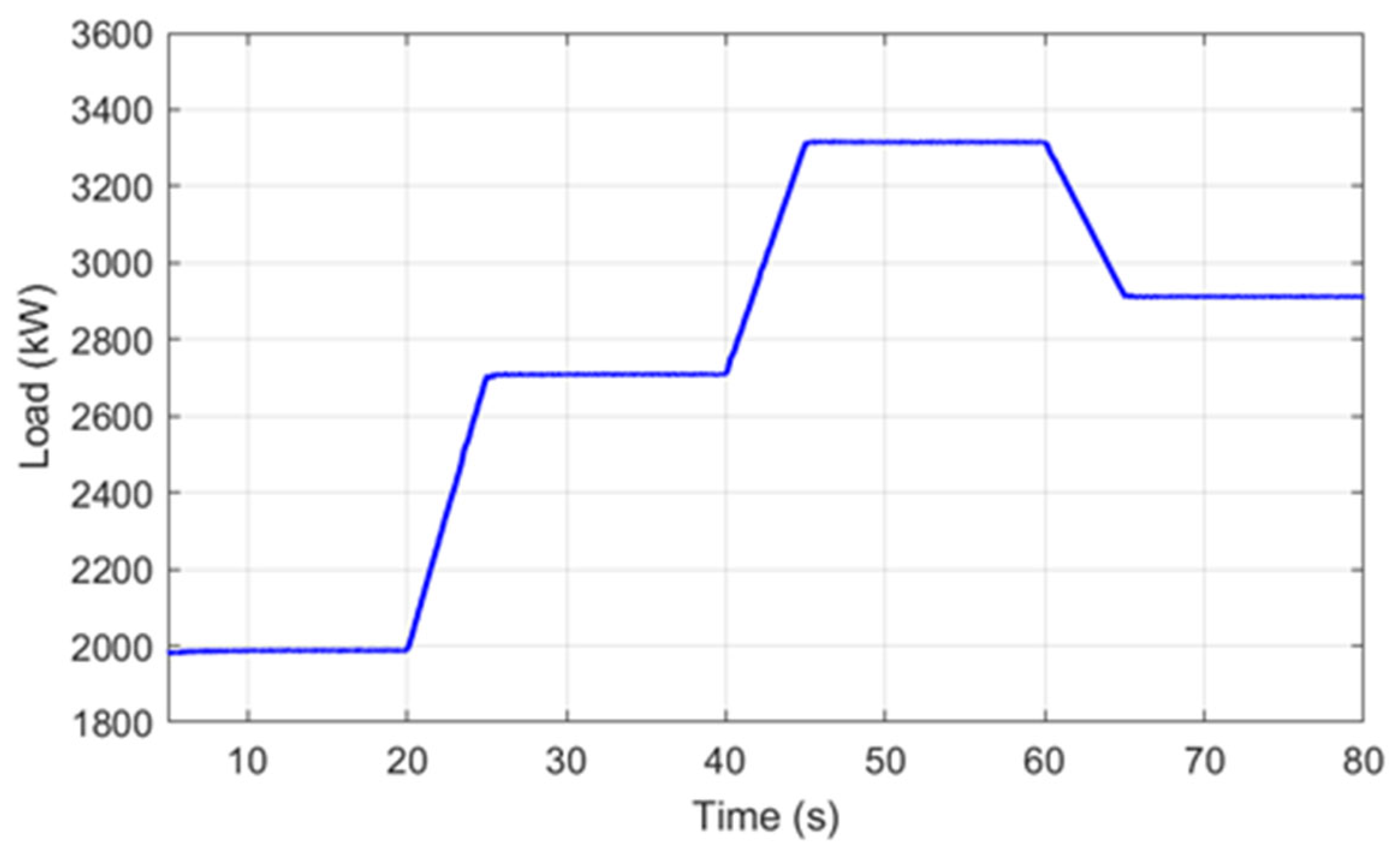
In Case 2, the overall system performance was evaluated under high-load conditions, where the load was above 50% of full load (>1.8 MW). The load scenario for the dynamic simulation of Case 2 is shown in Figure 20. The simulation was conducted in 80 s.
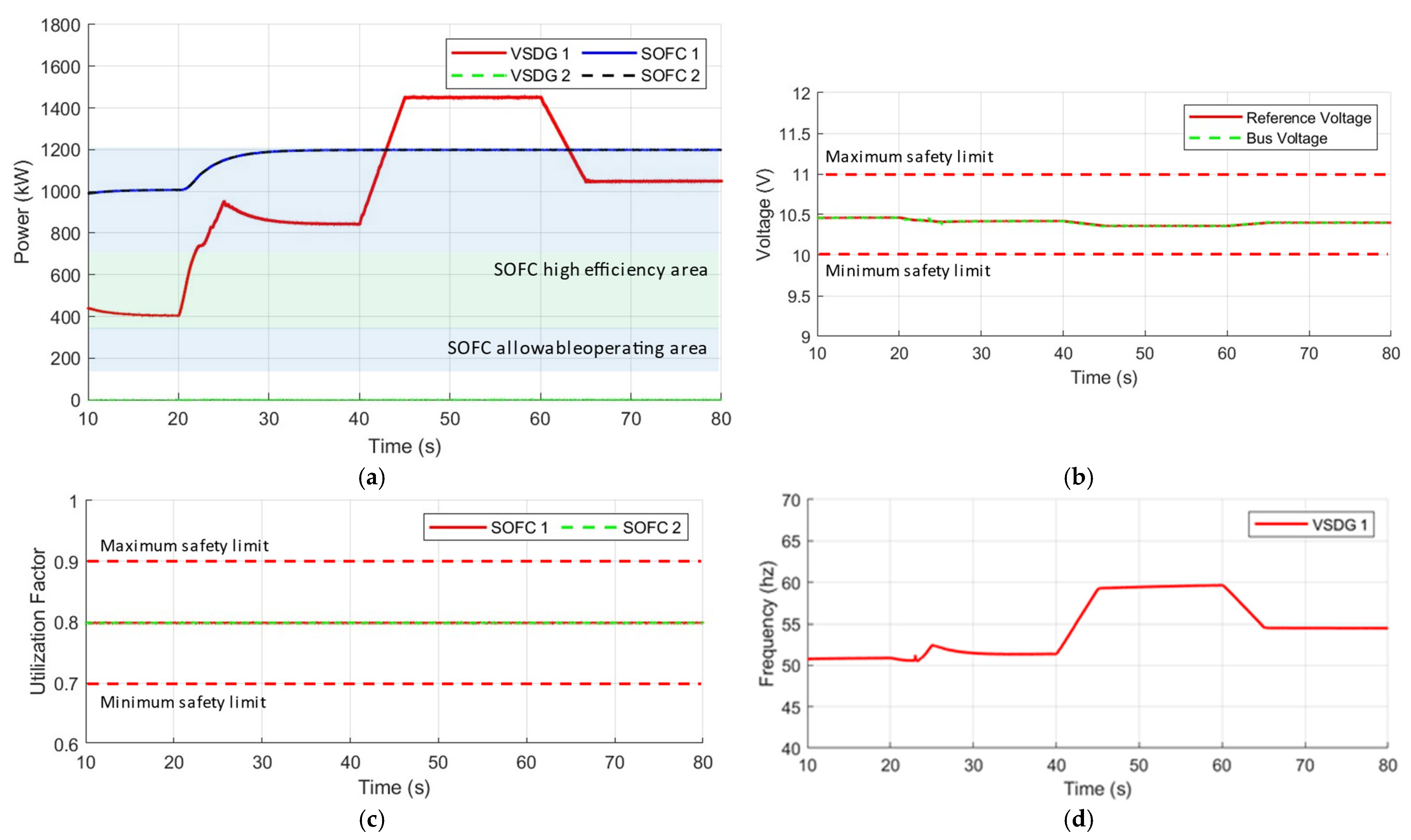
The power generation simulation results are depicted in Figure 21a. As the load surpassed the total maximum capacity range of the SOFCs, the VSDG increased its output beyond its minimum operating level to compensate for the excess demand. This dynamic ensured that the power balance of the system was maintained. However, owing to this high-demand condition, the SOFCs were forced to operate beyond their high-efficiency range, which might have resulted in increased fuel consumption and a slight efficiency reduction. This limitation is an inherent trade-off when meeting critical loads, where maintaining power availability takes precedence over maximizing efficiency. Although the SOFC dispatch control still functioned, its ability to prioritize operation within the most efficient region became constrained owing to load limitations. When the system demand exceeded the maximum combined optimal output of SOFCs, the controller shifted from the efficiency-maximizing mode to the capacity-maximizing mode. In this mode, all SOFCs were dispatched to their full capacity, and any shortfall was covered by the VSDG.
The voltage profile for Case 2 is shown in Figure 21b. Despite the SOFCs operating above their optimal power range, the bus voltage was effectively regulated throughout the entire simulation period. The voltage plot demonstrates that the system voltage consistently remained within the acceptable bounds defined by the red dashed lines, which represent the voltage safety margin around the primary reference voltage. This stability was achieved through the excitation control of the VSDG, which dynamically adjusted generator excitation in response to load changes. Even under high current flow and power transitions, the MVDC bus remained stable.
Figure 21c presents the dynamic simulation of the fuel utilization factor for both SOFC units during high-load conditions. Despite the fact that both fuel cells were operating near or at their power limits, the utilization factor for each remained tightly controlled around 0.8, well within the defined safe operational window of 0.7 to 0.9. This result demonstrated the robustness of the coordinated control, which continuously adjusted the input fuel flow based on real-time power demand and ensured safe electrochemical operation. Even under elevated load conditions and with increased output power, the controller successfully maintained utilization factor stability, preventing excessive fuel usage or fuel starvation, which could compromise the SOFC performance or lifespan.
The dynamic frequency behavior of the VSDG is illustrated in Figure 21d. Initially, as the system load increased, the power contribution of the VSDG was adjusted accordingly. The frequency increased in response to the required engine speed that minimized the SFC for a given load level. The frequency plot shows that the active VSDG followed this reference accurately, confirming the effectiveness of the governor-based speed control integrated into the fuel optimizer. Notably, even as the load increased, the frequency remained stable without introducing large oscillations, ensuring smooth system dynamics and safe operating conditions for the electrical equipment connected to the MVDC system. This dynamic tracking of frequency indicates that the system not only responds well to power demand fluctuations but also maintains fuel-efficient operation in the diesel engine. Because the VSDG fuel consumption is highly sensitive to the engine speed, it must be operated at the right frequency for each load level to minimize overall fuel costs. As the load began to decrease after 60 s, the VSDG frequency correspondingly returned to its lower reference, confirming the adaptive capability of the VSDG speed optimization logic.
To comprehensively evaluate the impact of the proposed coordinated control strategy under high-load conditions, a comparative fuel consumption analysis was conducted for five simulation scenarios, as presented in Table 7. In Scenario 1, which incorporated the complete proposed strategy, both SOFC units were dispatched to their full capacity while the VSDG operated at a load level that ensured total power balance. This configuration yielded a total SOFC fuel consumption of 1743 g and DG fuel consumption of 2880 g, resulting in a combined fuel cost of $5.252, which served as the reference for fuel savings. Interestingly, Scenario 2 produced the same fuel consumption and cost, even though the SOFC dispatch control was disabled. This result occurred because, under high-load conditions, the dispatch controller was constrained to activate all SOFC units at maximum output regardless of the high-efficiency area. Thus, under high load, the system naturally saturated the SOFC power capacity, and both Scenarios 1 and 2 converged to the same optimal operation in terms of fuel usage.
In contrast, Scenario 3, which disabled SOFC prioritization, demonstrated a drastic efficiency degradation. In this case, SOFC operation was nearly neglected, with the fuel consumption reduced to only 1098 g, while the VSDG took over most of the load, consuming 4175 g of diesel fuel. Considering that diesel fuel is more expensive than hydrogen, a steep increase in operational costs was observed, reaching $6.614, which is a 25.9% increase compared to Scenario 1. This clearly demonstrates the fuel and cost penalties of not prioritizing the SOFC under high load demand. Scenario 4 disabled only the variable speed control, resulting in a cost increase of 1.7%, while Scenario 5 disabled both the variable speed and prioritization, yielding nearly the worst performance, with $6.631 in fuel costs and a 26.3% increase, compared to the optimal case. Under high-load operation, the comparative experiments show that SOFC prioritization remains the dominant contributor to cost reduction, while DG variable-speed optimization provides an additional efficiency gain. Even when the SOFC dispatch benefit diminishes due to saturation at maximum SOFC power, the proposed strategy remains consistently superior to the benchmark strategies.
These results confirm that even under high-load conditions, where SOFCs were naturally driven to their limits, maintaining a coordinated control framework that included SOFC prioritization, dynamic dispatch, and DG speed adjustment can substantially reduce fuel costs. Notably, the DG variable speed control ensured that the diesel engine operated at fuel-optimal speeds aligned with the load demand, further enhancing the system’s efficiency. The combined effect of these strategies highlights that the proposed control method is robust across a wide range of operating conditions, not only reducing costs during light loading but also preserving efficiency under full-load stress. Prioritizing the SOFC over the VSDG can also reduce emissions for environmental friendliness.

5. Conclusions

This study proposed a coordinated control strategy for a hybrid MVDC shipboard power system that incorporates SOFCs and VSDGs to improve fuel consumption reduction and dynamic performance. The SOFC model enabled precise analysis of fuel utilization and fuel savings under load variations, while the VSDG model incorporated the influence of rotational speed on fuel consumption, providing a foundation for optimal speed control. Through these models, an upper-level coordinated controller was designed to allocate power between SOFCs and VSDGs effectively, ensuring that each source operates within its most efficient region.
Simulation results validated the effectiveness of the proposed strategy, showing that the SOFCs maintained stable operation within the desired utilization range and contributed high-efficiency power output. At the same time, the VSDGs operated at speed-dependent efficiency points, significantly reducing fuel consumption compared with conventional fixed-speed operation. The coordinated control framework successfully balanced efficiency, stability, and load-following capability.
Furthermore, the proposed system architecture aligns well with international regulatory trends aimed at reducing greenhouse gas emissions from maritime operations. By leveraging the high efficiency and low emissions of SOFCs in combination with the flexibility of VSDGs, the proposed control strategy contributes to the development of sustainable marine energy systems. Future research will focus on the implementation of the proposed strategy in hardware-in-the-loop platforms and its extension to broader energy management systems, including renewable energy sources and energy storage integration, to further improve system autonomy, resilience, and compliance with next-generation maritime energy standards.

Author Contributions

Conceptualization, M.A. and I.-Y.C.; methodology, M.A.; software, M.A.; validation, M.A. and I.-Y.C.; formal analysis, M.A.; investigation, I.-Y.C.; data curation, M.A.; writing—original draft preparation, M.A.; writing—review and editing, I.-Y.C.; supervision, I.-Y.C.; project administration, I.-Y.C. All authors have read and agreed to the published version of the manuscript.

Funding

This work was supported by the Korea Evaluation Institute of Industrial Technology (KEIT) grant funded by the Ministry of Trade, Industry and Energy (MOTIE) of Korea (Grant No. RS-2025-02633139), and by the Institute for Information & Communications Technology Planning & Evaluation (IITP) under the Information Technology Research Center (ITRC) support program funded by the Ministry of Science and ICT (MSIT) of Korea (Grant No. RS-2023-00259004).

Institutional Review Board Statement

Not applicable.

Informed Consent Statement

Not applicable.

Data Availability Statement

The original contributions presented in this study are included in the article. Further inquiries can be directed to the corresponding author.

Conflicts of Interest

The authors declare no conflicts of interest.

Nomenclature

Acronyms:
ACAlternating current
BESSBattery energy storage system
IMOInternational maritime organization
MVDCMedium-voltage direct current
PEMFCPolymer electrolyte membrane fuel cell
PIProportional integral
PSFBPhase-shifted full-bridge
PWMPulse-width modulator
SFCSpecific fuel consumption
SOFCSolid oxide fuel cell
VSDGVariable-speed diesel generator
Variable and parameters:
G o n / o f f m   Activation status of the mth VSDG
G p ( s ) PI controller for the SOFC power
G q ( s ) PI controller for the SOFC gas flow rate
G v ( s ) PI controller for the bus voltage
G ω ( s ) PI controller for the VSDG engine speed
I f c , h i g h n   Current in the MV side of the nth SOFC [A]
I f c , l o w n   Current in the LV side of the nth SOFC [A]
I g , d c m   Current of the rectifier output at the mth VSDG [A]
I l o a d Total current into the load side [A]
K v Voltage droop gain [Ω]
P f c m a x Maximum SOFC power [W]
P f c m i n Minimum SOFC power [W]
P f c o p t , m a x Upper limit of the optimum SOFC power [W]
P f c o p t , m i n Lower limit of the optimum SOFC power [W]
P f c r e f , t o t a l   Total SOFC power reference [W]
P f c r e f , n nth SOFC power reference [W]
P f c n   Power of the nth SOFC [W]
P g m i n Minimum VSDG power [W]
P g o p t , m a x Optimum VSDG power at the maximum speed [W]
P g o p t , m i n Optimum VSDG power at the minimum speed [W]
P g m   Power of the mth VSDG [W]
P l o a d Total power into the load side [W]
T m m   Mechanical torque of the mth VSDG [Nm]
V b u s Coupling bus voltage [V]
V b u s r e f   Primary bus voltage reference [V]
V f m   Field voltage of the mth VSDG [V]
V f c n   Voltage of the nth SOFC [V]
V g r e f , m   mth VSDG terminal voltage reference [V]
V g m   Line-to-line rms voltage of the mth VSDG [V]
mNumber of VSDGs
nNumber of SOFCs
q H 2 , i n n   Hydrogen flow rate of the nth SOFC [mol/s]
q f c n   Gas flow rate of the nth SOFC [mol/s]
q g m   Fuel flow rate of the mth VSDG [g/s]
ω g m a x Maximum VSDG rotational speed [rad/s]
ω g m i n Minimum VSDG rotational speed [rad/s]
ω g r e f , m   mth VSDG rotational speed reference [rad/s]
ω g m   Rotational speed of the mth VSDG [V]
f c m   Phase-shifted delay of the PSFB DC-DC converter [s]
τ f c SOFC power response time [s]

Appendix A

The set parameters of the VSDG model are summarized in Table A1.
Table A1. VSDG model parameters.
ParametersValues
Rated rms line-to-neutral voltage6.6 kV
Rated power1.5 MVA
Base angular frequency ( f e = 1 p.u.)60 Hz
Base mechanical torque ( T m = 1 p.u.)11,700 Nm
Base rotational speed ( ω g = 1 p.u.)126 rad/s
Base fuel consumption ( q g = 1 p.u.)60 g/s
Number of poles6
Unsaturated reactance at d-axis ( X d )1.014 p.u.
Unsaturated transient reactance at d-axis ( X d )0.314 p.u.
Unsaturated sub-transient reactance at d-axis ( X d )0.28 p.u.
Unsaturated reactance at q-axis ( X q )0.77 p.u.
Unsaturated sub-transient reactance at q-axis ( X q )0.375 p.u.

References

  1. Serra, P.; Fancello, G. Towards the IMO’s GHG goals: A critical overview of the perspectives and challenges of the main options for decarbonizing international shipping. Sustainability 2020, 12, 3220. [Google Scholar] [CrossRef]
  2. Chircop, A. The IMO initial strategy for the reduction of GHGs from international shipping: A commentary. Int. J. Mar. Coast. Law 2019, 34, 482–512. [Google Scholar] [CrossRef]
  3. Ahmadi, H.; Rafiei, M.; Igder, M.A.; Gheisarnejad, M.; Khooban, M.H. An energy efficient solution for fuel cell heat recovery in zero-emission ferry boats: Deep deterministic policy gradient. IEEE Trans. Veh. Technol. 2021, 70, 7571–7581. [Google Scholar] [CrossRef]
  4. Sazali, N.; Salleh, W.N.W.; Jamaludin, A.S.; Razali, M.N.M. New perspectives on fuel cell technology: A brief review. Membranes 2020, 10, 99. [Google Scholar] [CrossRef] [PubMed]
  5. Sapra, H.; Stam, J.; Reurings, J.; Van Biert, L.; Van Sluijs, W.; De Vos, P.; Visser, K.; Vellayani, A.P.; Hopman, H. Integration of solid oxide fuel cell and internal combustion engine for maritime applications. Appl. Energy 2021, 281, 115854. [Google Scholar] [CrossRef]
  6. Chen, W.; Tai, K.; Lau, M.W.S.; Abdelhakim, A.; Chan, R.R.; Ådnanes, A.K.; Tjahjowidodo, T. Optimal power and energy management control for hybrid fuel cell-fed shipboard DC microgrid. IEEE Trans. Intell. Transp. Syst. 2023, 24, 14133–14150. [Google Scholar] [CrossRef]
  7. Xiao, Z.-X.; Guan, Y.-Z.; Fang, H.-W.; Terriche, Y.; Guerrero, J.M. Dynamic and steady-state power-sharing control of high-efficiency DC shipboard microgrid supplied by diesel generators. IEEE Syst. J. 2021, 16, 4595–4606. [Google Scholar] [CrossRef]
  8. Islam, K.; Kim, D.; Abu-Siada, A. A review on adaptive power system protection schemes for future smart and micro grids, challenges and opportunities. Electr. Power Syst. Res. 2024, 230, 110241. [Google Scholar] [CrossRef]
  9. Zahedi, B.; Norum, L.E.; Ludvigsen, K.B. Optimized efficiency of all-electric ships by dc hybrid power systems. J. Power Sources 2014, 255, 341–354. [Google Scholar] [CrossRef]
  10. Sun, L.; Wu, G.; Xue, Y.; Shen, J.; Li, D.; Lee, K.Y. Coordinated control strategies for fuel cell power plant in a microgrid. IEEE Trans. Energy Convers. 2017, 33, 1–9. [Google Scholar] [CrossRef]
  11. Aziz, M.; Trinh, P.-H.; Hudaya, C.; Chung, I.-Y. Coordinated control strategy for hybrid multi-PEMFC/BESS in a shipboard power system. Electr. Power Syst. Res. 2025, 243, 111495. [Google Scholar] [CrossRef]
  12. Liu, Z.; Liu, Y.; Yu, Y.; Yang, R. Coordinated control and optimal flow of shipboard MVDC system for adapting to large pulsed power load. Electr. Power Syst. Res. 2023, 221, 109354. [Google Scholar] [CrossRef]
  13. Lin, Y.; Fu, L. A novel virtual admittance droop based inertial coordination control for medium-voltage direct current ship with hybrid energy storage. J. Energy Storage 2022, 56, 105962. [Google Scholar] [CrossRef]
  14. Li, Y.; Shen, J.; Lu, J. Constrained model predictive control of a solid oxide fuel cell based on genetic optimization. J. Power Sources 2011, 196, 5873–5880. [Google Scholar] [CrossRef]
  15. Pukrushpan, J.T.; Peng, H.; Stefanopoulou, A.G. Control-oriented modeling and analysis for automotive fuel cell systems. J. Dyn. Syst. Meas. Control 2004, 126, 14–25. [Google Scholar] [CrossRef]
  16. Dicks, A.L.; Rand, D.A. Fuel Cell Systems Explained; Wiley: Hoboken, NJ, USA, 2018. [Google Scholar]
  17. Haseltalab, A.; van Biert, L.; Sapra, H.; Mestemaker, B.; Negenborn, R.R. Component sizing and energy management for SOFC-based ship power systems. Energy Convers. Manag. 2021, 245, 114625. [Google Scholar] [CrossRef]
  18. Luckose, L.; Urlaub, N.; Wiedeback, N.; Hess, H.L.; Johnson, B.K. Proton exchange membrane fuel cell (PEMFC) modeling in PSCAD/EMTDC. In 2011 IEEE Electrical Power and Energy Conference; IEEE: Piscataway, NJ, USA, 2011; pp. 11–16. [Google Scholar]
  19. Bakan, A.F.; Altintaş, N.; Aksoy, I. An improved PSFB PWM DC–DC converter for high-power and frequency applications. IEEE Trans. Power Electron. 2012, 28, 64–74. [Google Scholar] [CrossRef]
  20. Kazimierczuk, M.K. Pulse-Width Modulated DC-DC Power Converters; John Wiley & Sons: Coshocton, OH, USA, 2015. [Google Scholar]
  21. Camara, M.B.; Dakyo, B. Coordinated control of the hybrid electric ship power-based batteries/supercapacitors/variable speed diesel generator. Energies 2023, 16, 6666. [Google Scholar] [CrossRef]
  22. Xu, L.; Guerrero, J.M.; Lashab, A.; Wei, B.; Bazmohammadi, N.; Vasquez, J.C.; Abusorrah, A. A review of DC shipboard microgrids—Part I: Power architectures, energy storage, and power converters. IEEE Trans. Power Electron. 2021, 37, 5155–5172. [Google Scholar] [CrossRef]
  23. Sul, S.K. Control of Electric Machine Drive Systems; John Wiley & Sons: Hoboken, NJ, USA, 2011. [Google Scholar]
  24. Fitzgerald, A.E.; Kingsley, C.; Umans, S.D. Electric Machinery; McGraw-Hill: New York, NY, USA, 2003. [Google Scholar]
  25. Amato, J.; Bose, A.; Bai, L. Optimization-based control of variable speed diesel generators. In 2025 59th Annual Conference on Information Sciences and Systems (CISS); IEEE: Piscataway, NJ, USA, 2025; pp. 1–6. [Google Scholar]
  26. Chua, L.W.; Tjahjowidodo, T.; Seet, G.G.; Chan, R. Implementation of optimization-based power management for all-electric hybrid vessels. IEEE Access 2021, 6, 74339–74354. [Google Scholar] [CrossRef]
Figure 1. Architecture of a hybrid SOFC/VSDG shipboard microgrid.
Applsci 16 01694 g001
Figure 2. MVDC shipboard configuration used to implement the proposed coordinated control.
Applsci 16 01694 g002
Figure 5. SOFC auxiliary system power consumption.
Applsci 16 01694 g005
Figure 6. Power and SFC characteristics of the SOFC system model.
Applsci 16 01694 g006
Figure 7. (a) Model and (b) PWM control mechanism of a PSFB DC-DC converter.
Applsci 16 01694 g007
Figure 8. VSDG with a diode rectifier model.
Applsci 16 01694 g008
Figure 9. SFC curve of a VSDG system.
Applsci 16 01694 g009
Figure 10. Block diagram of the coordinated control.
Applsci 16 01694 g010
Figure 11. Block diagram of a VSDG controller.
Applsci 16 01694 g011
Figure 12. P–ω curve of the VSDG.
Applsci 16 01694 g012
Figure 13. Block diagram of the SOFC controller.
Applsci 16 01694 g013
Figure 14. Conceptual framework of the proposed control strategy.
Applsci 16 01694 g014
Figure 15. Block diagram of the upper-level controller.
Applsci 16 01694 g015
Figure 16. Flowchart of the SOFC dispatch control.
Applsci 16 01694 g016
Figure 17. Flowchart of the VSDG dispatch control.
Applsci 16 01694 g017
Figure 18. Shipboard low-load scenario for dynamic simulation.
Applsci 16 01694 g018
Figure 19. Dynamic simulation results under a low load condition (load < 1.8 MW) for (a) shipboard power source generation, (b) bus voltage, (c) fuel utilization factor of SOFC, and (d) electrical frequency of VSDG.
Applsci 16 01694 g019aApplsci 16 01694 g019b
Figure 20. High-load scenario of the shipboard for dynamic simulation.
Applsci 16 01694 g020
Figure 21. Dynamic simulation results under high-load conditions (load > 1.8 MW) for (a) shipboard power source generation, (b) bus voltage, (c) fuel utilization factor of SOFC, and (d) electrical frequency of VSDG.
Applsci 16 01694 g021
Table 2. Parameters of the engine model.
SymbolDefinitionValues
a Quadratic coefficient of speed term4.5
b Linear coefficient of speed term6
c Constant offset of the torque curve2.5
ρ Weighting factor for torque penalty0.2
γ Weighting factor for speed penalty0.4
ω g , o p t Generator speed at minimum SFC0.9
Table 3. Characteristic comparison of the SOFC and VSDG.
SOFCVSDG
SFC~50 g/kWh (Low)~150 g/kWh (High)
Fuel Price~$0.0007/g (Low)~$0.0014/g (High)
EmissionCO2 = 324 g/kWh,
SOx = -,
NOx = 0.005 g/kWh
(Low)
CO2 = 550 g/kWh,
SOx = 12 g/kWh,
NOx = 14 g/kWh
(High)
Ramp Rate5 kW/s (Slow)50 kW/s (Fast)
Table 4. Simulation case parameters.
ParameterValuesDefinition
P f c o p t , m i n 350 kWLower limit of the optimum SOFC power
P f c o p t , m a x 700 kWUpper limit of the optimum SOFC power
P f c m a x 1200 kWMaximum SOFC power
P f c m i n 150 kWMinimum SOFC power
τ f c 3 sSOFC power response time
P g o p t , m i n 800 kWOptimum VSDG power at the minimum speed
ω g m i n 0.85 p.u.Minimum VSDG speed
P g o p t , m a x 1450 kWOptimum VSDG power at the maximum speed
ω g m a x 1 p.u.Maximum VSDG speed
P g m i n 400 kWMinimum VSDG power
V b u s r e f   10.5 kVPrimary bus voltage reference
K v 1 ΩDroop gain
n 2Number of SOFCs
m 2Number of VSDGs
f s 20 kHzPSFB switching frequency
Table 5. Comparative benchmark control strategies used in the simulation experiments.
Scenario1 (Proposed)2345
DG variable speed controlOOOXX
SOFC dispatch controlOXOOX
Prioritization of SOFC over DGOOXOX
Table 6. Comparative experiment results of Case 1.
Scenario
1 (Proposed)2345
SOFC fuel consumption521 g544 g16 g521 g23 g
DG fuel consumption1425 g1425 g2865 g1535 g2943 g
Total fuel cost$2.360$2.376$4.022$2.514$4.316
Fuel cost saving (compare with scenario 1)-−0.7%−70.4%−6.5%−75.3%
Table 7. Comparative experiment results of Case 2.
Scenario
1 (Proposed)2345
SOFC fuel consumption1743 g1743 g1098 g1743 g1123 g
DG fuel consumption2880 g2880 g4175 g2943 g4175 g
Total fuel cost$5.252$5.252$6.614$5.340$6.631
Fuel cost saving (compare with scenario 1)-0%−25.9%−1.7%−26.3%
Disclaimer/Publisher’s Note: The statements, opinions and data contained in all publications are solely those of the individual author(s) and contributor(s) and not of MDPI and/or the editor(s). MDPI and/or the editor(s) disclaim responsibility for any injury to people or property resulting from any ideas, methods, instructions or products referred to in the content.