1. Introduction
Potentially unstable rock blocks are widely distributed on natural and excavated slopes associated with hydropower projects and represent a significant threat to infrastructure safety and operational reliability. These rock masses may occur as isolated blocks, unstable rock bodies, or boulder clusters bounded by intersecting discontinuities. Once free surfaces are formed, they may undergo sliding, toppling, or falling under the combined effects of gravity, water pressure, seismic loading, weathering, and excavation disturbance [
1,
2]. Instability of high and steep rock slopes has been reported in many mountainous regions, where earthquakes, glacial action, intense rainfall, and river incision are among the principal triggering factors [
3]. Therefore, reliable stability assessment and the development of effective reinforcement strategies are essential components of the design, construction, and operational management of hydropower infrastructure.
Since the mid-twentieth century, several theoretical frameworks and analytical methods have been developed for rock slope stability assessment. Block theory represents discontinuities and excavation surfaces as planar geometries and applies geometric topology to identify removable blocks and possible failure modes. Under the assumptions of planar discontinuities, rigid-block behavior, and translational movement, the method can distinguish detachment, single-plane sliding, and double-plane sliding mechanisms. By integrating geometric analysis with rigid-body limit equilibrium, block theory has been extensively applied to rock slopes and underground excavations [
4,
5,
6,
7]. However, its assumptions of persistent discontinuities and predominantly translational motion may restrict its applicability to blocks bounded by multiple sliding surfaces, blocks with irregular or concave geometries, and cases in which rotational effects or progressive failure are important.
Limit equilibrium methods (LEMs) constitute another widely used framework for slope stability analysis. Conventional two-dimensional methods, including the Bishop simplified method, Janbu’s method, the Morgenstern–Price method, and Spencer’s method, have been extensively developed and incorporated into engineering design standards [
8,
9,
10]. The Morgenstern–Price and Spencer methods satisfy both force and moment equilibrium and therefore provide relatively rigorous two-dimensional solutions [
11,
12,
13]. Nevertheless, two-dimensional methods reduce a spatially complex rock block to a representative cross-section under plane-strain assumptions. This simplification excludes lateral discontinuities and three-dimensional constraints and may therefore produce biased stability estimates when the block geometry is highly asymmetric or when lateral resistance contributes substantially to the overall mechanical response.
Three-dimensional LEMs have been developed to overcome these limitations. In these approaches, the sliding mass is generally discretized into columns or sub-blocks, and assumptions regarding inter-column or inter-block forces are introduced to obtain a statically determinate solution. Some formulations satisfy only force equilibrium, whereas others incorporate both force and moment equilibrium through additional governing equations. The three-dimensional residual thrust method considering moment equilibrium can iteratively identify a mechanically admissible sliding direction and evaluate the corresponding factor of safety [
14,
15,
16]. Compared with conventional two-dimensional analyses, three-dimensional methods can more explicitly represent irregular geometries, multiple sliding surfaces, lateral constraints, and spatially distributed loads. However, their implementation requires detailed geometric and mechanical input data and generally involves greater modeling and computational effort.
Specialized methods have also been developed for the analysis and mitigation of potentially unstable rock blocks. These include limit equilibrium formulations for sliding, toppling, and falling mechanisms, as well as wedge stability analyses based on block theory. Recent studies have addressed the effects of volumetric and morphological uncertainty on high-position rock blocks [
17], combined matter-element and block-theory approaches for rockfall risk assessment [
18], and prestressed anchor systems with dual anchorage segments for large unstable rock masses [
19]. Numerical simulations have further contributed to understanding the progressive failure of block systems and the coupled reinforcement effects of rock bolts [
20,
21]. In parallel, terrestrial LiDAR and photogrammetry-based three-dimensional point clouds have improved the characterization of discontinuity networks and provided detailed geometric data for block identification and stability modeling [
22].
Despite these advances, several challenges remain in the stability assessment process for potentially unstable rock blocks. First, conventional engineering practice often relies on two-dimensional LEMs in which a three-dimensional block is simplified as a unit-width profile. Such treatment neglects the resisting contribution of lateral discontinuities and may not adequately represent the spatial force-transfer mechanism. Second, large rock blocks intersected by several discontinuity sets may be controlled by the combined action of multiple sliding surfaces, whereas simplified methods generally consider only one dominant basal plane [
23,
24]. Third, the influence of modeling assumptions, including block discretization, inter-block force transfer, and moment equilibrium, on calculated safety factors and reinforcement requirements has not been sufficiently clarified. Although the block-dividing LEM and the three-dimensional residual thrust method provide alternative approaches for multi-sliding-plane blocks, systematic comparisons of their performance for the same geometry, mechanical parameters, and loading conditions remain limited [
25,
26].
This study develops a comparative stability-assessment workflow for a single, well-characterized sliding-type rock block located on a hydropower station slope; the conclusions are restricted to this block and are not generalized into class-wide method-selection rules. Building on the multi-sliding-plane block-dividing formulation and the three-dimensional residual-thrust formulation developed by the authors’ group [
16,
21,
25,
26], the discontinuity-controlled geometry is first characterized, and the block is then evaluated with a conventional two-dimensional LEM, a block-dividing LEM, and a three-dimensional residual-thrust method, all sharing one parameter set. Factors of safety and sliding directions are compared under natural, heavy-rainfall and seismic conditions, after which anchorage forces for two installation orientations are calculated and compared.
The main objectives of this study are to: (1) quantify the differences between two-dimensional and three-dimensional stability assessments for a rock block bounded by multiple discontinuities; (2) evaluate the consistency and applicability of two three-dimensional limit equilibrium formulations with different discretization and equilibrium assumptions; and (3) investigate the influence of anchorage orientation and moment equilibrium on reinforcement requirements. The resulting workflow provides a practical basis for analytical method selection, stability evaluation, and support design for potentially unstable rock blocks in hydropower and related infrastructure projects.
2. Destabilization Modes of Dangerous Rock Mass
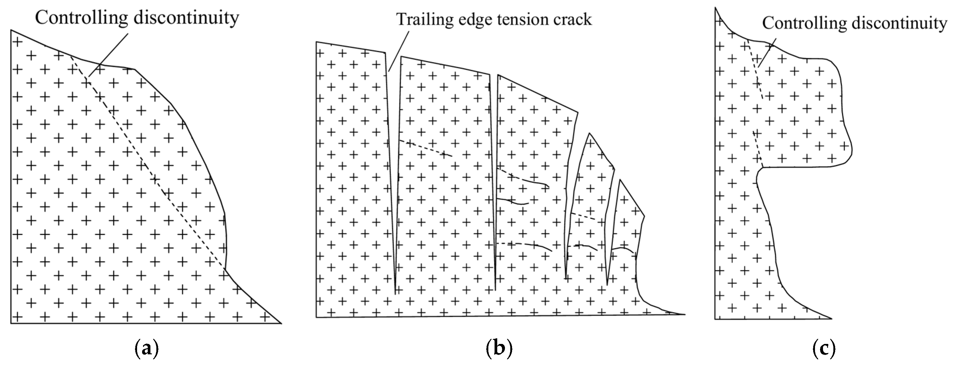
Dangerous rocks are commonly classified by scale, kinematic mode and failure pattern; from an engineering prevention standpoint the three principal kinematic modes are sliding, toppling and falling (
Figure 1).
Sliding-type failures occur when a discontinuity dips out of the slope and the trailing-edge fracture propagates through the plane; under hydrostatic pressure and self-weight the overlying rock mass gradually displaces along the basal plane. Toppling-type failures involve rotation of a columnar or tabular rock mass about a basal pivot under gravity, and falling-type failures involve free detachment from a steep or overhanging face. The block studied in this paper is of the sliding type.
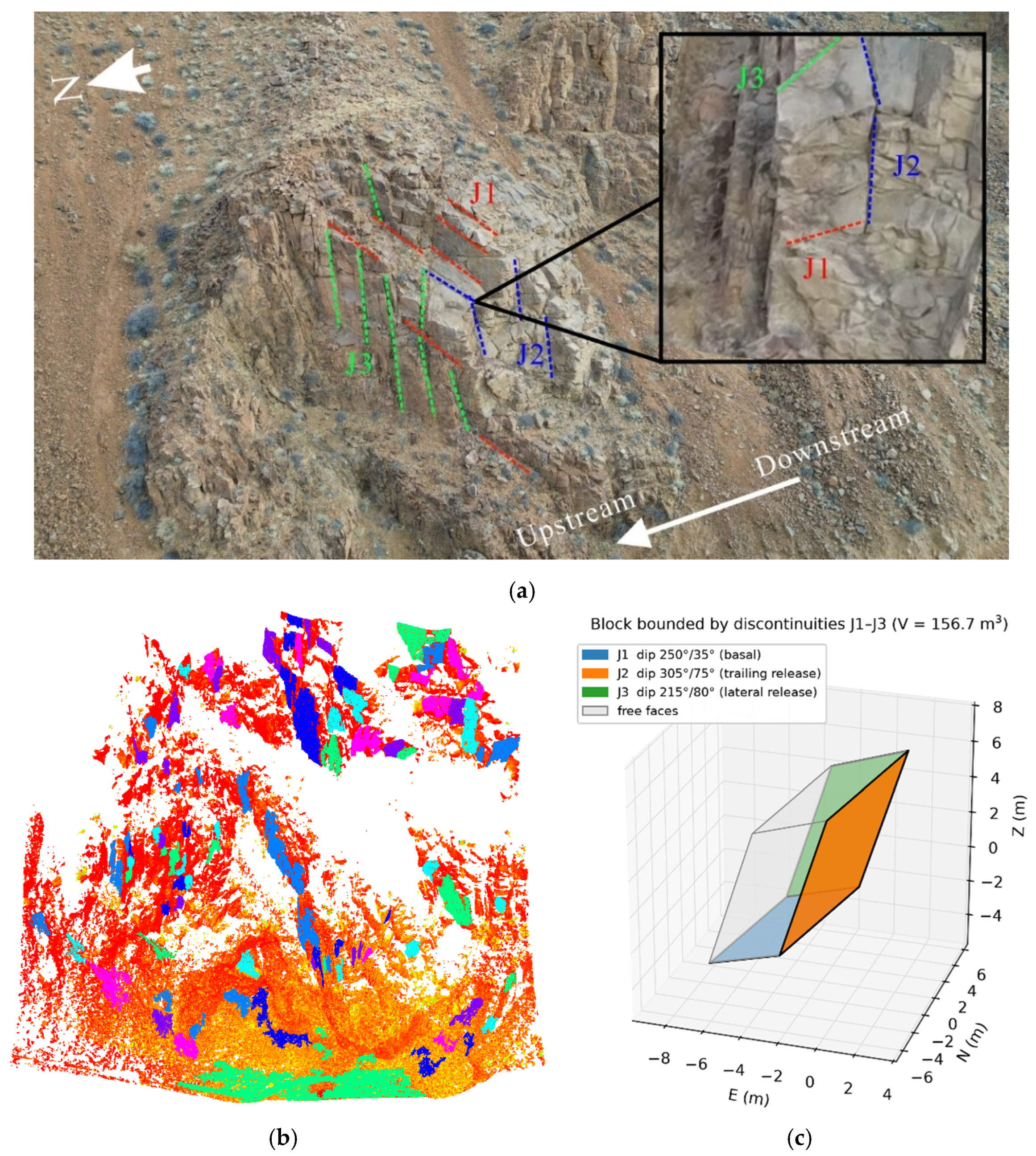
The investigated canyon slope is composed mainly of granite and is overall stable. The slope aspect is 240° and the slope angle is 30°. Discontinuity attitudes were measured in the field with a geological compass and a terrestrial three-dimensional laser scanner, and the slope surface was reconstructed by UAV photogrammetry. Three dominant discontinuity sets define the dangerous rock mass (
Figure 2): J1 (dip direction 250°, dip 35°) is the basal sliding plane, J2 (dip direction 305°, dip 75°) is the nearly through-going trailing-edge release surface, and J3 (dip direction 215°, dip 80°) is the lateral boundary. The reconstructed parallelepiped block has a volume of 156.7 m
3 and a weight of 4243.8 kN, and is classified as a sliding-type block. Its stability is sensitive to the excavation boundary, so the intervention scope and support intensity must be evaluated from the geometry, failure mode and stability state.
3. Stability Calculation of the Dangerous Rock Mass
All three methods share one common parameter set and one common geometry. The rock unit weight is γ = 27.08 kN/m3. The three discontinuity areas, obtained from the reconstructed block, are A1 = 30.86, A2 = 32.45 and A3 = 39.78 m2. Cohesion acts over the full area of J1, over zero area of the through-going release plane J2 and over 20% of J3 (its residual rock bridge), whereas friction acts over the full area of every plane; the lower-bound cohesion (50 kPa natural/seismic, 47 kPa rainfall) is used as the representative value. Under heavy rainfall the water filling heights are 1.0, 2.6 and 1.8 m on J1–J3 (γw = 10 kN/m3), and the horizontal seismic coefficient is ξ = 0.20 with no vertical component.
3.1. Global Analysis Method (Conventional Method)
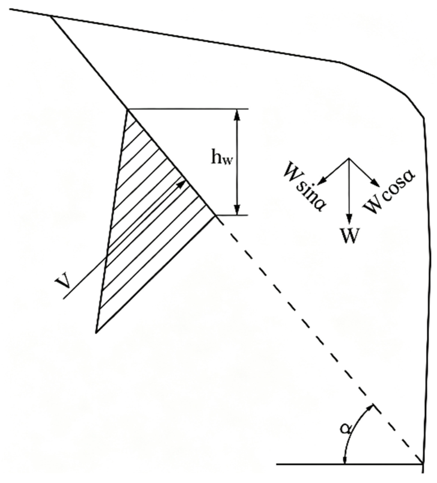
When the basal sliding plane of the dangerous rock mass dips out of the slope, the stability mainly relies on the anti-sliding effect of the discontinuity and the locking effect of the rock bridge (
Figure 3). The calculation formula is as follows:
where
is the factor of safety of the dangerous rock mass;
W is the weight of the dangerous rock mass per unit width (kN/m);
c is the cohesion of the trailing edge fracture (kPa);
is the internal friction angle of the trailing edge fracture (°);
l is the length of the sliding plane (m);
a is the dip angle of the weak structural plane (°), taken as positive when dipping out of the slope and negative when dipping into the slope;
Q is the seismic force (kN/m), calculated by
, where
is the horizontal seismic coefficient (for a seismic intensity of VIII,
);
V is the static water pressure in the fracture (kN/m),
, where
hw is the water filling height (m) and
is the unit weight of water, taken as 10 kN/m
3.
Parameters are taken per unit width, with the three-dimensional block represented by a representative cross-section normal to the slope aspect. The section area is 30.0 m
2, giving W = γA = 812.40 kN/m and a basal trace length l = 3 m; a single friction value is used per case (tan26.6° = 0.5008 for natural/seismic, tan23° = 0.4245 for rainfall), and the seismic force is Q = ξW = 0.20 × 812.40 = 162.5 kN/m (horizontal coefficient ξ = 0.20, intensity VIII). The results (
Table 1) show that the block is marginally stable under natural conditions (Fs = 1.037) and unstable under heavy rainfall (0.904) and seismic (0.729) conditions.
3.2. Block-Dividing Limit Equilibrium Method
For a block bounded by several non-free faces, for which classical block theory does not directly yield a stability coefficient, the block-dividing limit-equilibrium method is applicable [
21,
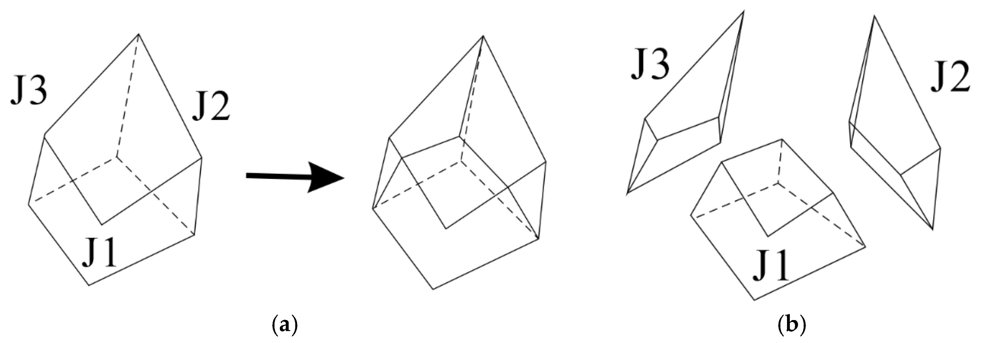
25]. The block has three sliding faces: J1 is the primary basal plane, and J2 and J3 are secondary planes. The reconstructed block volume is 156.7 m
3; its geometry is shown in
Figure 4a and the divided sub-blocks in
Figure 4b.
Following the multi-sliding-plane block limit-equilibrium method, the block is divided vertically along the intersections of the sliding planes into three sub-blocks, each associated with one sliding plane; inter-block vertical shear is neglected and only horizontal interaction is retained. A fine vertical division on a 0.02 m grid (verified mesh-converged: refining from 0.10 m to 0.01 m changes the natural factor only from 1.172 to 1.169) gives sub-block weights W1 = 3087.2, W2 = 641.0 and W3 = 515.6 kN, summing to 4243.8 kN. For sub-block
i, the normal force on its sliding plane follows from vertical equilibrium:
where
is the normal force on the sliding plane of sub-block
i;
Wi is the weight of sub-block
i;
and
are the water pressure and unit normal vector on the sliding plane;
and
are water pressures on other planes;
and
are external loads (e.g., seismic or anchor forces); and
is the vertical unit vector. The resisting force
on the sliding plane is expressed by the strength reduction definition:
Here
,
, and
are the friction coefficient, cohesion, and area of the sliding plane, respectively, and
is the overall factor of safety. The direction of
, denoted
, is such that its horizontal projection opposes the assumed sliding direction, which is represented by the unit vector
. For the entire block, force equilibrium in the sliding direction (horizontal) is enforced as:
Similarly, equilibrium perpendicular to the sliding direction (with unit vector
) yields:
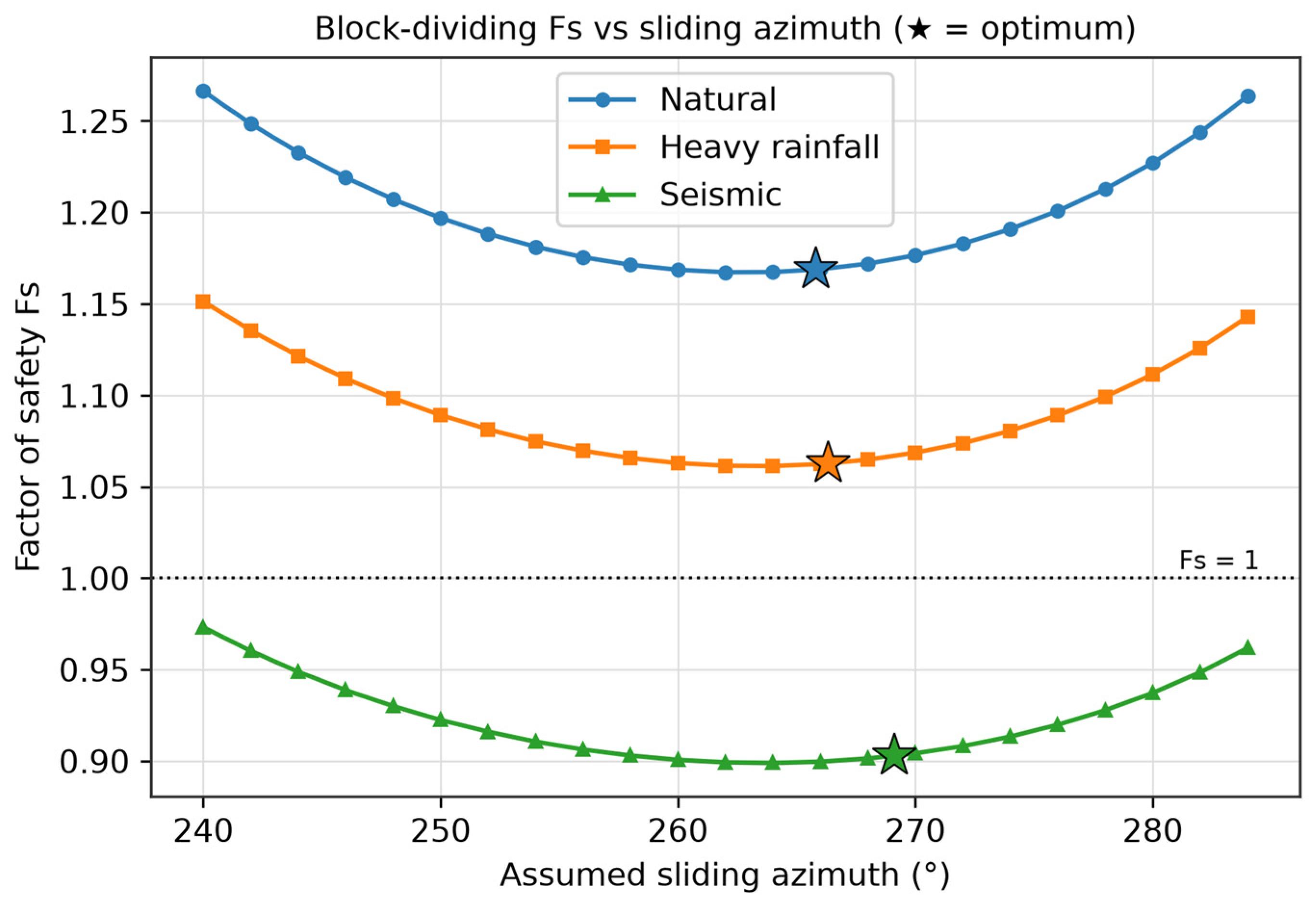
By varying the assumed sliding azimuth until , the optimal sliding direction is obtained. At this direction, the factor of safety reaches its minimum. When the unbalanced force equals zero, the forces in all three directions (the gravity direction and the two horizontal orthogonal directions) achieve equilibrium; at this point, the stability coefficient is exactly the desired solution of calculation, and the corresponding sliding direction represents the optimal sliding trajectory of the block. The optimal sliding direction is oriented upstream and is perpendicular to the slope, exhibiting slight variations with different shear strength parameters of the sliding faces adopted in calculation.
Under natural conditions the common friction coefficient is tanφ = 0.5008 (φ = 26.6°) and the lower-bound cohesion is c = 50 kPa, acting over the full area of J1, over zero area of the through-going J2 and over 20% of J3 (a 20% rock bridge). Iterating over the assumed sliding azimuth gives the factors and unbalanced forces in
Table 2; the optimum is 265.8° with Fs = 1.169. Under heavy rainfall the water forces on J1–J3 are U1 = 10.9, U2 = 65.5 and U3 = 31.7 kN, and the three-case results are given in
Table 3.
Because the block-dividing method includes the resisting contribution of the lateral planes J2 and J3, its factors (1.169, 1.063, 0.903) exceed the two-dimensional values (1.037, 0.904, 0.729) by 12.7%, 17.6% and 23.9%, and the difference widens as the loading becomes more severe. The optimal direction is oriented upstream, approximately normal to the slope aspect, and rotates by only a few degrees between cases (
Figure 5).
3.3. Three-Dimensional Residual Thrust Method with Moment Equilibrium
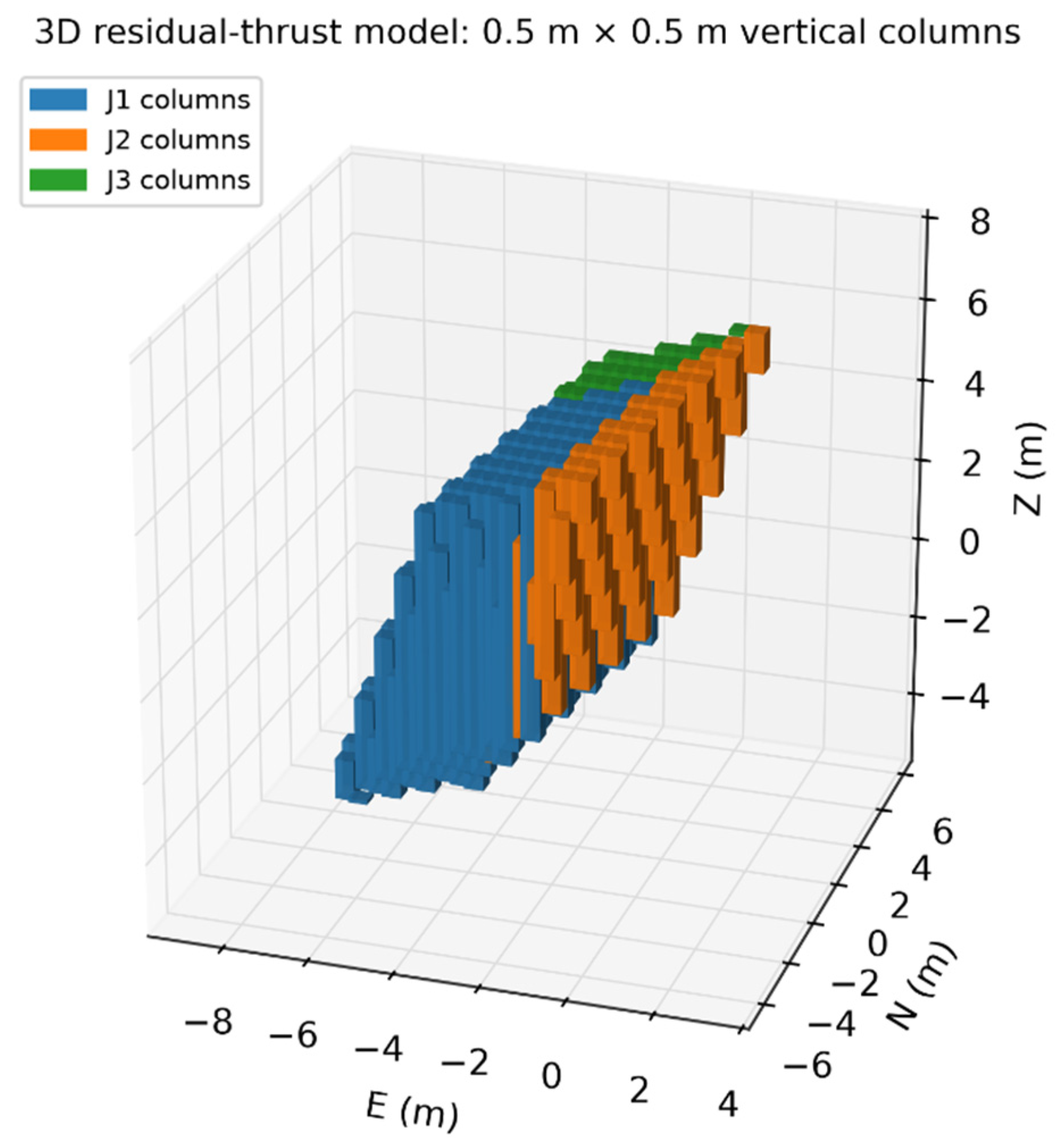
The three-dimensional residual thrust method adopts the conventional bar-column technique to segment the block into discrete columns 0.5 m × 0.5 m in plan (
Figure 6); each column is kept in limiting equilibrium.
A basic assumption is that the horizontal shear component of inter-column forces can be neglected. On row interfaces (between columns in the sliding direction), the direction angle of the inter-column force is taken as the dip angle of the base sliding surface of the upstream column multiplied by an unknown correction coefficient
; on column interfaces (perpendicular to sliding), the direction angle is taken as the apparent dip angle of the base surface in the Y-direction. These assumptions are expressed as:
where Ex and Tx are the normal and vertical shear forces on the row interface, Ey and Ty those on the column interface, and the inter-column force apparent dips are defined unambiguously from the base-normal components by tanαx = −nx/nz and tanαy = −ny/nz.
For each column (
i,
j), the equilibrium equations in the vertical direction (Z), the sliding direction (X), and the direction perpendicular to sliding (Y) are established. Additionally, moment equilibrium about the Y-axis is enforced over the entire sliding mass. The resisting force
on the base of each column follows the same strength reduction form as Equation (3). By substituting the force direction assumptions, the normal force
and the row interface normal force
can be solved from the following system derived from vertical and X-direction equilibrium:
where nz, nx, ny are the base-normal components of the column, ŝ is the in-plane resisting direction, f is the friction coefficient, and a1, a2, b1, b2, m1–m5 are known coefficients assembled from the geometry, strength and loads of the column. For reproducibility these coefficients are defined in full as follows:
The base resistance of each column is Equation (3) and the sweep proceeds row by row; the moment-closure condition about the sliding-frame Y axis, taken relative to the block centroid, is:
The overall solution procedure is iterative:
- (1)
For a given sliding direction and a trial , compute and row by row and column by column using Equation (8).
- (2)
Adjust until the sum of the residual thrusts in the X-direction (the last column of each row) becomes zero.
- (3)
Vary the assumed sliding azimuth (X-axis direction) and repeat steps (1) and (2) until the total residual thrust in the Y-direction (the last row of each column) becomes zero. This azimuth is the optimal sliding direction.
- (4)
Under this optimal sliding direction, change the correction coefficient and repeat steps (1) and (2). Compute the total moment about the Y-axis. Find that makes this moment zero, and the corresponding is the final factor of safety.
The discontinuity parameters are identical to those of
Section 3.1 and
Section 3.2 and the column plan size is 0.5 m × 0.5 m. Setting the correction coefficient λ = 1 (see below) gives the results in
Table 4: 1.497, 1.324 and 1.049 at optimal azimuths of about 253°.
For this sharply bounded block the moment-closure Equation (13) does not give a physically admissible λ (the zero-moment root is ill-conditioned), so the well-defined λ = 1 solution is reported. A grid check with 0.25, 0.5 and 1.0 m columns gives natural factors of 1.789, 1.497 and 1.492 with the optimum shifting from 247° to 253°, i.e., the column solution is not fully mesh-converged; by contrast, the block-dividing solution is mesh-converged (1.172 → 1.169 as its grid is refined from 0.10 to 0.01 m). This contrast is discussed in
Section 3.4.
3.4. Comparative Analysis
The three methodologies exhibit fundamental disparities in theoretical rigor, dimensionality, and mechanical assumptions, necessitating careful selection in engineering practice.
3.4.1. Differences in Mechanical Assumptions
The two-dimensional global method reduces the block to a unit-width profile supported by the basal plane J1 alone, excluding the lateral planes and all internal force transfer; it cannot represent the three-dimensional weight distribution, so for this block it is the most conservative (lower-bound) estimate.
The block-dividing method partitions the block onto all three sliding planes. Neglecting vertical inter-block shear while retaining horizontal transfer keeps the problem statically determinate and, as shown in
Section 3.2, is mesh-converged. It does not enforce moment equilibrium, an acceptable simplification for this moderate-sized block; its key strength is that the optimal sliding direction follows objectively from zeroing the transverse unbalanced force.
The residual-thrust method discretizes the mass into columns and enforces three-directional force equilibrium plus moment equilibrium through λ. For this block, however, the lateral release planes J2 and J3 dip at 75° and 80°, and the moment-closure equation does not yield a physically admissible λ; the column solution is also mesh-sensitive (
Section 3.3). It therefore provides an upper-bound rather than a design value here.
3.4.2. Analysis of Calculation Results
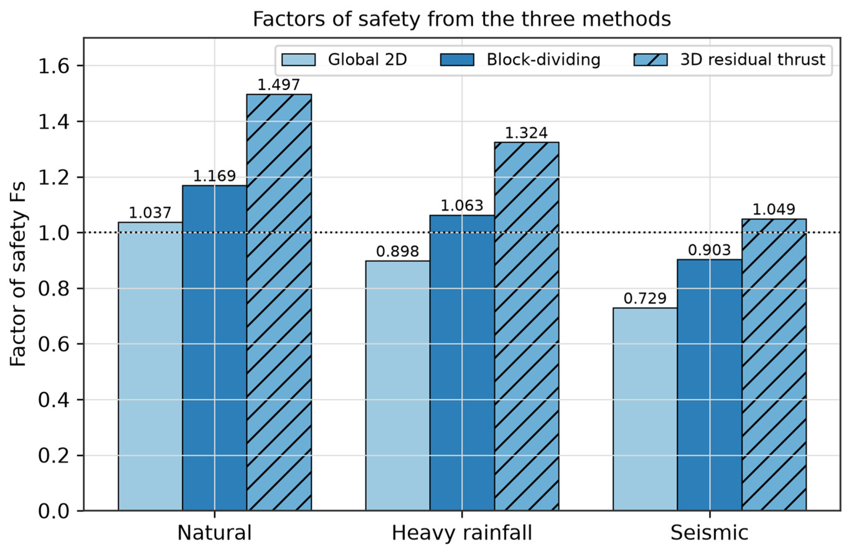
For the studied block, run on one identical geometry and parameter set, the three methods give the factors in
Table 5 and
Figure 7.
The block-dividing factors exceed the two-dimensional profile by 12.7% (natural), 17.6% (rainfall) and 23.9% (seismic), because the two-dimensional profile cannot represent the lateral resistance and the true three-dimensional weight distribution; its conservatism grows as the seismic or water load increases relative to the fixed cohesion.
The residual-thrust factors (1.497, 1.324, 1.049) lie a further 16–28% above the block-dividing values (and 44–47% above the two-dimensional profile). With inclined inter-column forces, the steep lateral columns shed most of their overburden onto the gently dipping basal plane, where normal force is converted into resisting force more efficiently; this redistribution is an artefact of the steep bounding planes rather than additional physical resistance.
The moment-correction coefficient λ has no physically admissible root for these 75°/80° bounding planes, and a grid check (0.25/0.5/1.0 m) gives 1.789/1.497/1.492, i.e., the column solution is not mesh-converged; the 0.5 m value is reported only as a representative upper bound, in contrast to the mesh-converged block-dividing solution.
The optimal block-dividing directions (265.8°, 266.3°, 269.1°) are oriented upstream and roughly normal to the slope aspect, whereas the residual-thrust directions (252.9°, 252.9°, 252.7°) are closer to the dip direction of J1; the small load-dependent rotation of the block-dividing direction is a three-dimensional feature that a two-dimensional analysis cannot reveal.
3.4.3. Applicability Discussion
The two-dimensional global method is appropriate for simple blocks with poorly developed or non-persistent lateral planes and for preliminary screening; for this block, where the lateral planes do participate, it serves as a conservative lower bound.
The block-dividing method is suited to multi-sliding-plane blocks that require lateral resistance but not dominant moment effects; it is mesh-converged, computationally efficient and well suited to scheme comparison and sensitivity analysis, and it is used as the design basis in
Section 4.
The residual-thrust method is intended for large or asymmetric blocks and eccentric loads where moment equilibrium is essential; for hard-rock blocks bounded by very steep planes it must be applied cautiously, because λ may be ill-defined and the column result mesh-sensitive and non-conservative, as found here.
For the studied single block the ordering is two-dimensional (lower bound) < block-dividing (design basis) < residual-thrust (upper bound); this ranking is established for this block only and is not presented as a universal rule.
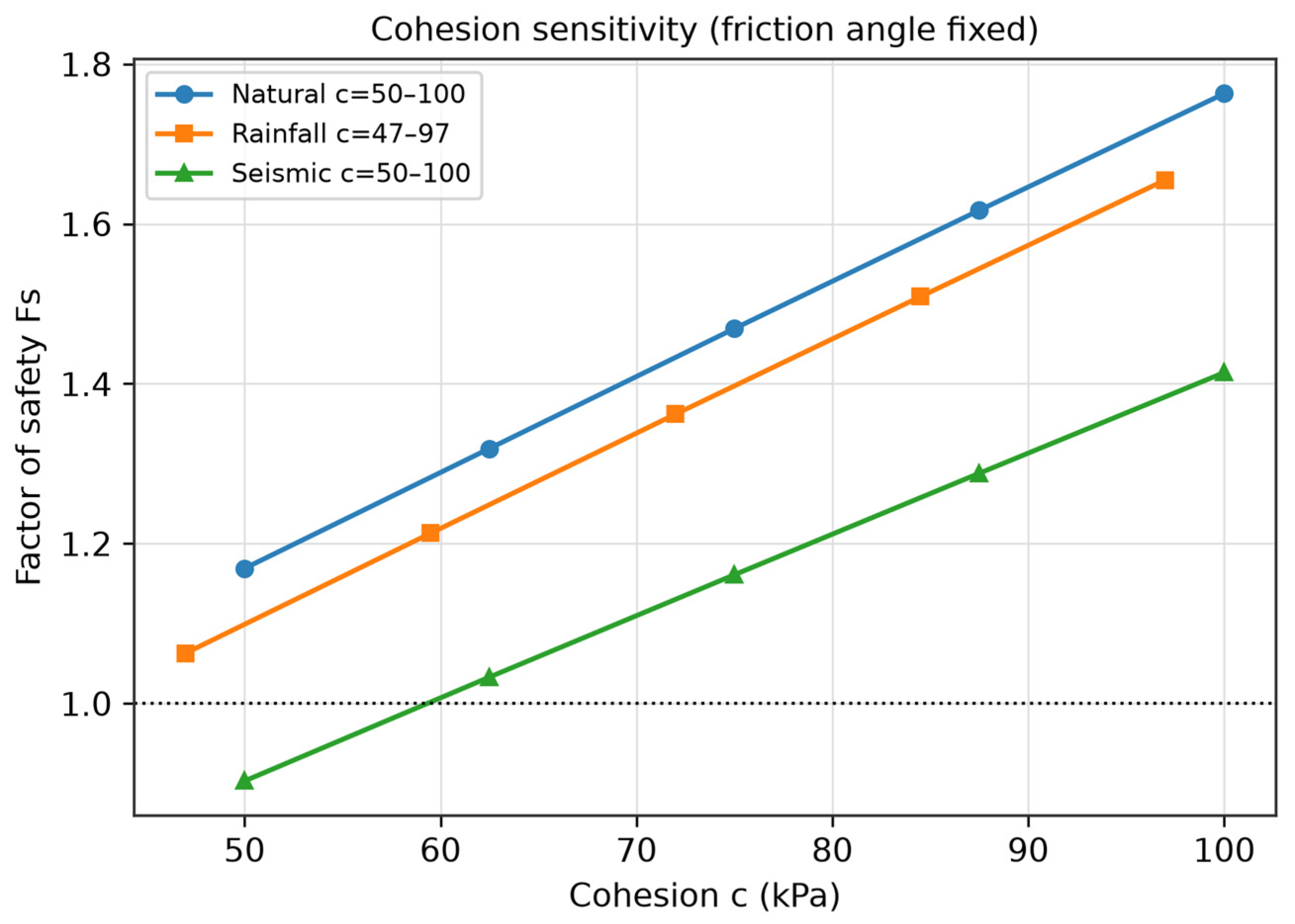
3.4.4. Cohesion Sensitivity
Because the site-suggested cohesion is an interval while the friction angle is comparatively well constrained, only cohesion is varied over its suggested range (50–100 kPa natural/seismic and 47–97 kPa rainfall) with φ fixed. The block-dividing factor rises from 1.169 to 1.763 (natural), 1.063 to 1.655 (rainfall) and 0.903 to 1.414 (seismic), a 51–57% variation (
Table 6,
Figure 8); cohesion is therefore the dominant parameter uncertainty and the lower-bound value is retained for design.
4. Block Support Analysis
The block-dividing method is taken as the design basis because it is the rigorous, mesh-converged three-dimensional solution, lying above the conservative two-dimensional lower bound and well below the non-conservative residual-thrust upper bound. Its unreinforced factors are 1.169 (natural), 1.063 (heavy rainfall) and 0.903 (seismic), all below the code targets. Following NB/T 10137-2019 (Specification for Engineering Geological Investigation and Prevention of Perilous Rock in Hydropower Projects) and T/CSRME 040-2024 [
27,
28] (Technical Specification for Block Stability Analysis of Engineering Rock Mass), the target factors for a Class I hazardous rock mass are 1.30 (natural), 1.20 (heavy rainfall) and 1.05 (seismic).
Two anchorage orientations are compared, both installed at azimuth 60° into the slope: a horizontal anchor (dip 0°) and an anchor perpendicular to the basal plane (dip 58°). The lower-bound cohesion of each case is retained; the vertical component of the anchor is assigned to the basal sub-block on J1.
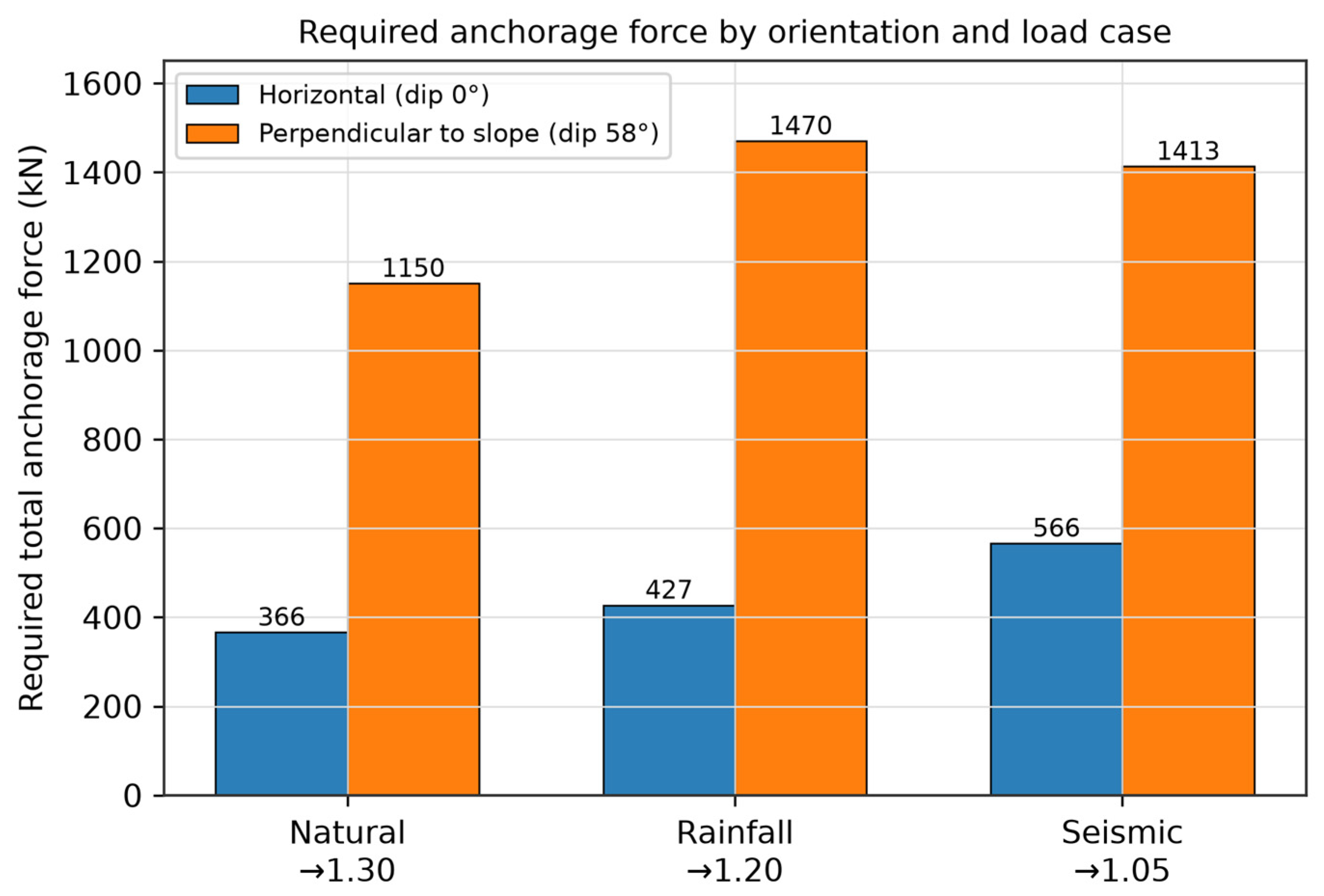
The total anchorage forces required to reach the target factor in each case, for both orientations, are given in
Table 7 and
Figure 9.
The horizontal layout requires only 31–40% of the force of the perpendicular-to-slope layout (
Table 7). At the low friction of these planes (tanφ ≈ 0.50), a perpendicular (near-normal) anchor adds mainly normal force, each kN of which generates only tanφ ≈ 0.50 of resisting force, whereas a horizontal anchor acts almost along the resisting direction and contributes about cos26° ≈ 0.90 per kN; the normal-clamp advantage therefore does not compensate for its lower tangential efficiency here. The seismic case controls the design at 566 kN, so a horizontal anchorage of about 0.6 MN is recommended.
5. Conclusions
This study established a comparative analytical workflow for evaluating the stability and anchorage requirements of a sliding-type, potentially unstable rock block on a hydropower station slope. Based on the characterization of the discontinuity-controlled geometry and failure mechanism, three limit equilibrium approaches were applied under natural, heavy-rainfall, and seismic loading conditions. The main conclusions are as follows:
- (1)
Using one common, fully documented parameter set (γ = 27.08 kN/m3; lower-bound cohesion over the full area of J1, zero on the through-going J2 and 20% of J3; friction over the full area), the two-dimensional, block-dividing and residual-thrust methods give factors of 1.037/0.904/0.729, 1.169/1.063/0.903 and 1.497/1.324/1.049 under natural/rainfall/seismic conditions. The block-dividing optimum directions are 265.8°, 266.3° and 269.1°.
- (2)
The block-dividing result exceeds the two-dimensional profile by 12.7–23.9%, with the gap widening as loading becomes more severe, while the residual-thrust result is a further 16–28% higher. The latter is traced to inclined inter-column thrust on the steep (75°, 80°) lateral planes; λ has no physical root and the column solution is mesh-sensitive, so the residual-thrust result is treated as an upper bound and block-dividing as the design basis.
- (3)
A cohesion sensitivity analysis with fixed friction angle shows that the factor varies by 51–57% across the suggested cohesion interval (
Figure 8), demonstrating that cohesion is the dominant uncertainty and that a lower-bound design value is appropriate.
- (4)
Under the code targets 1.30/1.20/1.05, horizontal anchorage requires 366/427/566 kN versus 1150/1470/1413 kN for a perpendicular-to-slope layout; because tanφ ≈ 0.50 makes normal clamping inefficient, a horizontal scheme of about 0.6 MN (seismic-controlled) is adopted.
- (5)
Limitations and future work. The conclusions rest on one block and on limit-equilibrium assumptions; no finite-element analysis and no field piezometric or displacement monitoring data were available for this block, and these are required to validate the computed factors and the performance of the recommended anchorage in subsequent work.
Overall, the comparative workflow clarifies the influence of dimensional assumptions, lateral constraints, and moment equilibrium on rock-block stability assessment and anchorage design. The results provide a practical basis for selecting appropriate analytical methods and optimizing reinforcement schemes for potentially unstable rock blocks in hydropower and related infrastructure projects.