1. Motivation
Radon is a colorless and chemically inert noble gas that is radioactive and decays by emitting
radiation. It is primarily released from geological formations containing uranium and radium. Radon is one of the most significant contributors to human exposure to natural radiation [
1,
2]. The concentrations of radon in ambient air are also relevant to physical experiments and meteorological observations, such as elevated radon levels shortly before earthquakes [
3]. To evaluate these effects, the radon concentration needs to be measured as accurately and as quickly as possible.
In outdoor air, radon disperses rapidly, resulting in typical activity concentrations of only a few
. In enclosed spaces, however, such as buildings, basements, bunkers, or mine tunnels, a significant accumulation can occur, with concentrations sometimes reaching several thousand
. When radon-laden air is inhaled, a portion of the gas decays into solid active progencies that deposit in the respiratory tract and continue emitting
radiation. In that way, the lung tissue is damaged. Radon is therefore considered the second leading cause of lung cancer after smoking; Paracelsus described these health risks as “miners’ disease”. The gas itself was identified around 1900, but legally binding regulations for radon protection in the European Union only came into force in the 2010s [
4].
From the perspective of health risks, the isotope
222Rn, which has a half-life of 3.82 days, is particularly important. In contrast,
220Rn (thoron) decays much faster, with a half-life of only 54 s. The main elements in the decay chain of
222Rn are:
Ionization chambers (ICs), especially pulse-proportional ICs with airflow, enable the direct measurement of
222Rn. The
particles of the decaying radon and its progeny ionize the air, creating free charge carriers that are collected by an electric field. The concentration of
222Rn is determined from the resulting charge pulse. Radon measurement with ICs is precise and is therefore used in calibration laboratories, for long-term monitoring, and in research; see e.g., [
5,
6,
7,
8,
9]. When activity levels are low, as much air as possible should be used for the measurement to achieve an acceptable measurement uncertainty with the shortest possible measurement time. For example, at a radon concentration of
in a 1 L measuring chamber,
decays of
222Rn occur within 30 min. With the statistical assumptions of a Poisson distribution, the relative uncertainty of the measurement is
, i.e., 10.5%. With a measurement volume of 5l, this uncertainty is already reduced to 4.7%. In practice, however, existing ICs have a significantly higher measurement error. This results mainly from non-optimal designs but also from acoustic and vibration interference (the microphonic effect).
Early pulse ICs that use spectroscopy as a measurement method are described in [
5,
6,
10,
11,
12]. The papers [
10,
11] and subsequent publications of the authors use various multi-wire pulse ICs for their measurements. The results have quite low resolution. Under ideal conditions in a calibration mine, a 10% full width at half maximum (FWHM) of the
222Rn frequency distribution was achieved during long-term measurements. Under real-world measurement conditions, however, these results cannot be reproduced.
In addition to the inherent problems caused by the microphonic effect, this is also due to the applied design principle and the chosen premise of generating uniform charge-carrier collection times. This implies that the distances between the electrodes should be as uniform as possible, and the electric field should be as homogeneous as possible using thick wires. In [
13], it was shown that charge-collection time also depends strongly on the electrode dimensions, bias voltage, and environmental parameters such as pressure, temperature, and humidity.
Other recent systems illustrate different design priorities. In [
14], a compact 3.3 L pulse IC with low-noise amplification, pulse discrimination, data processing, and PC-based control was presented. The system was intended primarily for robust radon monitoring rather than high-resolution
spectroscopy. The work in [
15] used a symmetrical twin-type airflow pulse IC and differential amplification to suppress common-mode noise. Although this improved the signal-to-noise ratio, the reported energy resolution of approximately 40% for
241Am remained insufficient for resolving individual radon-progeny peaks.
Electrostatic collection provides another approach to low-level radon monitoring. In the NEMO experiment, positively charged radon progeny were collected on a PIN photodiode, and the
214Po peak was used to determine the radon concentration [
16]. This method achieved very high sensitivity, but its collection efficiency depended on the charge state of the progeny and on impurities such as water vapor or alcohol [
16]. It therefore differs fundamentally from the direct measurement of ionization charge in a pulse IC.
Alternative pulse-IC designs were investigated in [
5,
6,
12]. In [
5], a large multi-wire pulse IC with an active volume of 16.8 L was presented. Due to its conventional setup and the resulting lack of compensation for the microphonic effect, this IC achieves resolutions of between 4 and 10% FWHM, but only after extensive optimization measures (sound insulation, electromagnetic shielding). Due to these measures, the chamber’s weight increased to over 150 kg, rendering the system unsuitable for mobile use.
An incidental finding made during the development of the measurement cell described in [
17] led to the concept and construction of a coaxial pulse-proportional IC. This chamber was tested in [
12] as a small system with a chamber volume of 3.3 L, and FWHMs of less than 2% were achieved for the first time. Therefore, this work serves as the point of departure for our development.
This article presents a double-cylindrical IC that enables significantly more accurate radon measurements in ambient air. The specific design of this IC, combined with additional measures for vibration insulation, enables short measurement times and high-resolution spectroscopy.
2. Design and Measurement Principle of the Ionization Chamber
Radon and its decay products ionize the air through the emitted particles, producing and ions, as well as electrons. The electrons can be discarded because they recombine with oxygen within microseconds, whereas the ions are collected in the IC, which is basically a capacitor with air as the dielectric. At ambient conditions and a typical voltage of 1 to , the ions drift at about 5–10 mm/ms and then hit the electrode. In the IC, these charges are measured as voltage pulses.
2.1. Design
ICs are typically cylindrical; the air to be analyzed is sucked in perpendicular to its axis. The capacitance
C of a cylindrical capacitor is
where
is the permittivity of the vacuum and
is the relative permittivity of air;
l is the length of the cylinder, and
and
are its outer and inner diameter, respectively.
The commonly used multi-wire ICs are designed so that the electric field strength and the path lengths the ions must travel within the chamber are approximately equal. In that case, the amplitude of the signals depends theoretically only on the energy of the
particles. The signals can be counted and evaluated using spectroscopy. Such a construction is achieved, for example, by a capacitor structure in which the electrodes consist of parallel rods arranged at equal intervals and positioned in a spiral around a longitudinal axis; see
Figure 1 and [
11,
18,
19,
20,
21].
However, the many physical obstacles along the ions’ trajectories cause a relatively large number of them to collide prematurely at lower energy, thereby losing their energy. These
decays are then no longer available as counting events and degrade the statistics. In addition, vibrations, e.g., due to ambient noise or footfall, alter the distance between the electrodes of the charged capacitor and thus its capacitance
C. This leads to voltage fluctuations that introduce low-frequency interference signals into the measured signal. The situation is illustrated in
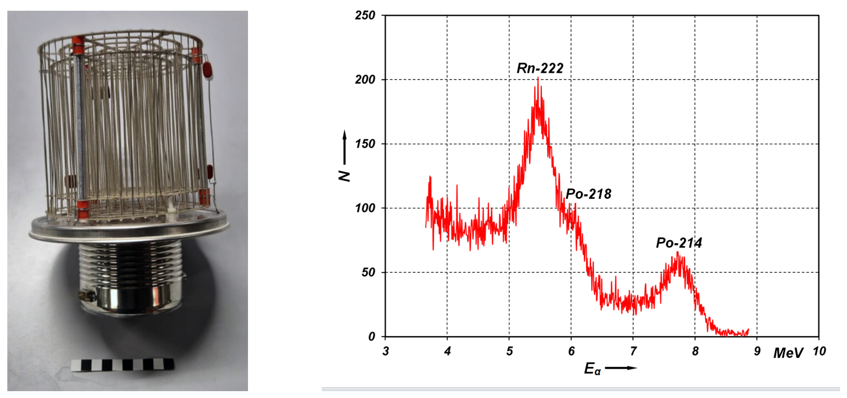
Figure 1, where a multi-wire chamber that we constructed [
19,
20] following the ideas of [
11] is shown. The arrangement of electrodes in multiple concentric rings ensures uniform electric field strengths, but a very large fraction of the ions collide prematurely. As a result, a large number of pulses with low, unattributable energy are counted. The measurement diagram shown illustrates the poor resolution. Energies below 3 MeV are partial energies of the radon decay chain and additionally appear as strong noise in the spectrogram.
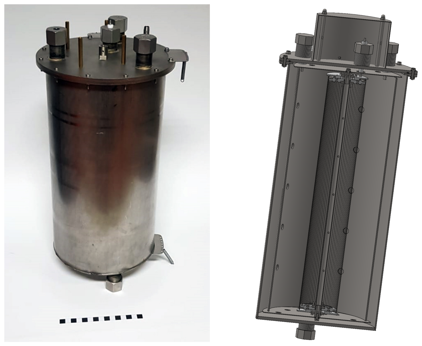
For these reasons, a cylindrical, impulse-proportional ionization chamber (CIPIC) is suggested here. Two coaxial cylindrical tubes form the anodes of the capacitor, and the cathode is formed by thin wires arranged cylindrically, see
Figure 2. The capacitance
C is then
where
,
and
are the diameters of the outer, middle and inner electrodes.
This double-cylindrical design avoids obstacles and allows for an undisturbed flight for the vast majority of decays. Then, the number of ions is indeed proportional to the charge. The measured voltage pulse is used to determine the energy of the corresponding particle. For example, it is 5.49 MeV for 222Rn, 6 MeV for 218Po, and 7.68 MeV for 214Po. However, we note that the maximum signal varies at the same energy due to differences in charge-carrier collection times. This is due to the different trajectories of the particles relative to the geometry of the CIPIC and cannot completely be excluded.
The double-cylindrical design, together with appropriately selected geometric dimensions, reduces the error of measurement. For the capacity of the outer capacitor to be equal to that of the inner one, i.e., , it must hold . A corresponding choice of diameters minimizes the influence of mechanical disturbances because the capacities of the two partial capacitors and depend inversely on the diameter .
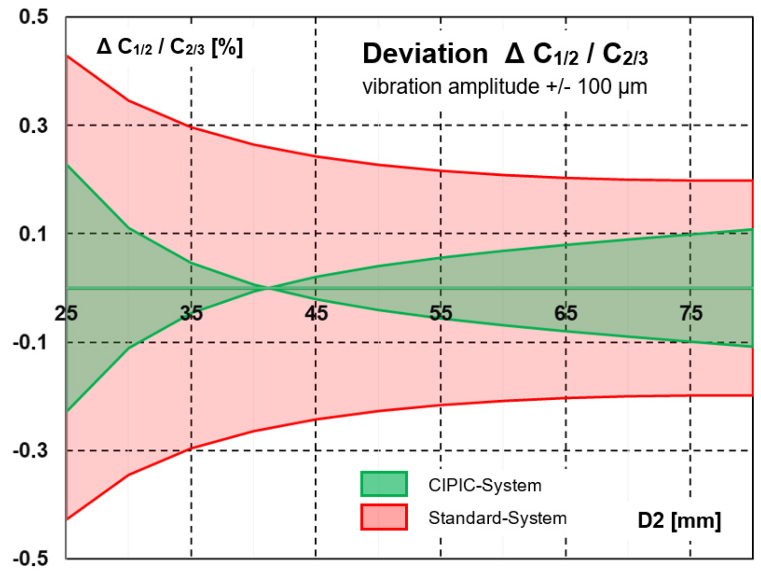
The effect is exemplarily illustrated in
Figure 3. With the fixed dimensions we have chosen,
mm and
mm, it follows the optimal mid diameter
mm and the capacitance (here scaled by
)
. If the tensioned wires now move by
mm in the radial direction, e.g., as a result of an oscillation, the capacitances change to
and
. This corresponds to a relative capacitance change of
%. If the chamber were a simple capacitor with the same total capacitance according to (
1), the oscillating electrode would result in a capacitance change of
. The error in the measured signals would be correspondingly larger.
For technical reasons, our CIPIC does not exactly match the optimal design. We chose mm, mm, mm and a length of mm. The cylindrical multi-wire cathodes consist of 72 wires with a diameter of m. The chamber is made of stainless steel and has an effective chamber volume of 7.7 l. The CIPIC has an intrinsic capacitance of approximately 100 pF. All insulators were made of polytetrafluoroethylene to ensure the highest possible insulation resistance (approx. 10 T).
2.2. Vibration Insulation
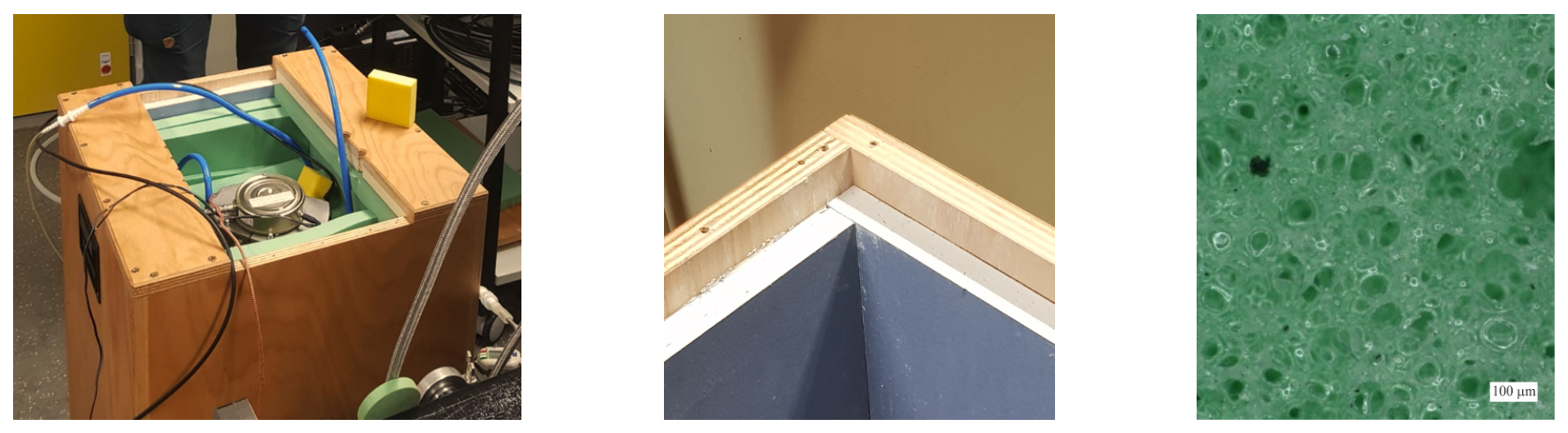
For acoustic insulation, the ionization chamber was installed inside a robust wooden enclosure. The interior walls of the enclosure were lined with 18 mm thick plasterboard, a relatively heavy but slightly porous wall covering that absorbs sound from the surroundings.
For additional vibration insulation, the housing was mounted on custom-designed elastomer buffers. The material chosen was the soft polyurethane foam
Regufoam vibration 150 [
22]. It has a low relative density of 15%, is designed for loads up to a compression of
, and has a modulus of elasticity of
. The setup is illustrated in
Figure 4.
Four elastomer feet were designed to dampen low-frequency noise emissions such as those associated with cadence and impact noise. The mass of the CIPIC and its enclosure is approximately 50 kg. Therefore, each foot must absorb a force of 125 N, which, given a contact area A with , results in a foot’s edge length of mm. Its deflection is approximately 5%.
When using elastomer layers of height
h for vibration decoupling, these act like a spring with stiffness
. For a layer height of 50 mm, we thus obtain
N/mm
2, which leads to a natural frequency
of
Hz. Starting at approximately twice this frequency
(exactly
), the amplitude of the vibration decreases significantly. The cutoff frequency for effective vibration decoupling is thus
Hz. In the common frequency range of 50 Hz, this mounting achieves an insulation efficiency of nearly 100%.
These combined passive insulation measures result in excellent attenuation of room (airborne) and impact (structure-borne) noise.
2.3. Signal Path and Data Collection
To determine the 222Rn concentration, the accumulated voltage signal is detected and evaluated spectroscopically. The ions are collected at the cathode (the middle electrode, with diameter ) and generate a positive charge here. This results in a positive voltage of up to 100 V. This signal is detected, amplified, and further evaluated using a sensitive spectroscopy amplifier. To suppress electromagnetic interference, the system is surrounded by an electrically conductive shield that is grounded with low resistance. The measuring chain has five steps:
A CIPIC;
A Charge amplifier, a low-noise BF862-type FET with a signal-to-noise ratio of 50:1;
An Instrument amplifier, which decouples the reference mass from the spectroscopy amplifier and generates a low-impedance measurement signal (INA111), with a total gain of 2000;
A USB sound card, which digitalizes the unipolar signal;
A Computer, which records the data at a sampling rate of 44,100 Hz, which fully complies with the Nyquist–Shannon theorem, in a wav file.
Further collection, evaluation and processing of the data are performed in Matlab R2025a [
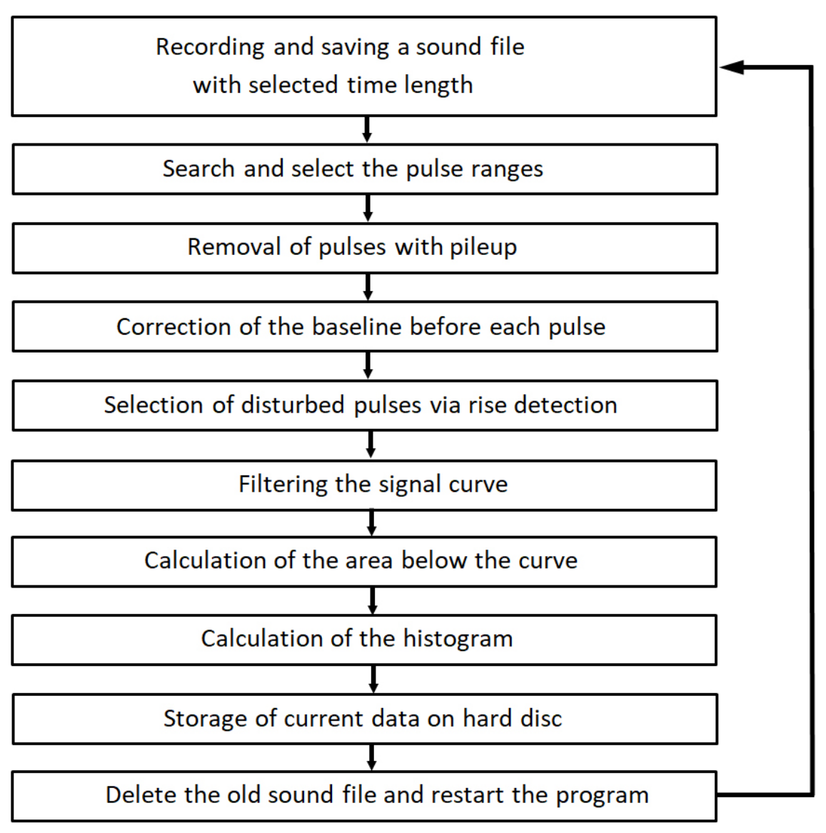
23]. After a measurement time of approx. 15–60 min, the wav file is sequentially searched for sections containing signal curves of
decays, and these are evaluated as shown in
Figure 5.
3. Results
To test the measurement setup under realistic conditions, the CIPIC unit was installed and commissioned in the Solid-State Mechanics Laboratory at the University of Siegen. The radon concentration in the indoor air is unremarkable because there are no radium-bearing geological formations nearby. Consequently, the 222Rn concentration is in the range of 50–100 . Measurements were taken here over several months.
Typical measurement data recorded during this period are shown in
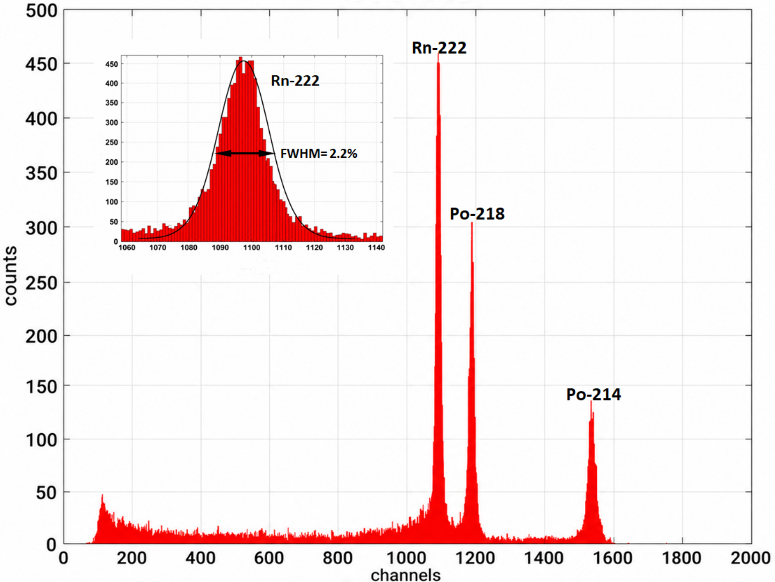
Figure 6. The spectra show clearly defined peaks that can be attributed to the decays of
222Rn,
218Po and
214Po. The energy resolution achieved is approximately 2%, corresponding to an FWHM of 100 keV. Due to the high counting statistics, the transfer function—or instrument response—of the CIPIC system is evident.
In
Figure 6 and below, the energy is displayed over 2000 channels in a range of 0…10 MeV; i.e., a channel has a width of 5 keV. Then, the concentration of
222Rn and progenies is determined from the measured pulse-height spectrum. The areas of the individual peaks are proportional to the number of recorded decay events and thus form the basis for determining the activity. A Crystal Ball Function (CBF) is used to model the peak shapes. A CBF consists of a Gaussian core and a low-energy power-law tail. The transition to the power-law tail occurs below a defined threshold, so that the function is described by four free parameters that are fitted to the experimental histogram data. Due to its ability to model an asymmetric detector response, the CBF provides a good approximation of the CIPIC detector’s instrument function.
Here, a fitting model consisting of a superposition of three CBFs was employed. It describes the contributions of the dominant emitting nuclides in the spectrum. We remark that the number of events per channel is often less than five, particularly during short measurement times. Therefore, the maximum-likelihood method was used for parameter estimation. At low counting rates, it is more suitable than conventional fits and enables a robust determination of the CBF parameters and the peak areas.
Subsequently, the activity concentration of the air sample under investigation is calculated from the measured decay rate, the measurement duration, the effective chamber volume, and the experimentally determined detection efficiency of the ionization chamber. Based on this calibration, the CIPIC detector, with an active volume of about 8 L, can determine a radon activity concentration of within 30 min with a relative uncertainty of no more than 5%. Activity concentrations of can be detected under comparable conditions within approximately 5 h with similar accuracy.
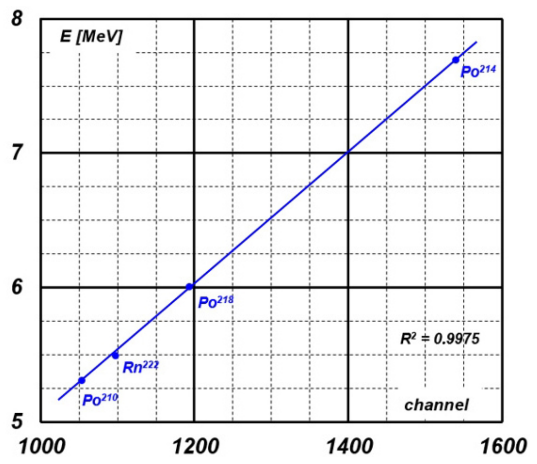
In addition, the linearity of the CIPIC was investigated. The linearity of a detector describes how well the chamber’s output signal is proportional to the incident radiation intensity; that is, if the radiation intensity changes, the measured signal (current) should change in the same way. This linearity should hold over as wide a range of radiation intensities as possible.
Figure 7 shows the corresponding values measured with our CIPIC. With a coefficient of determination of
, there is an excellent agreement between the charge measured in the CIPIC and the actual energy released by the
decays. In the relevant energy range of 5 to 8 MeV, the system behaves in a nearly ideal linear manner.
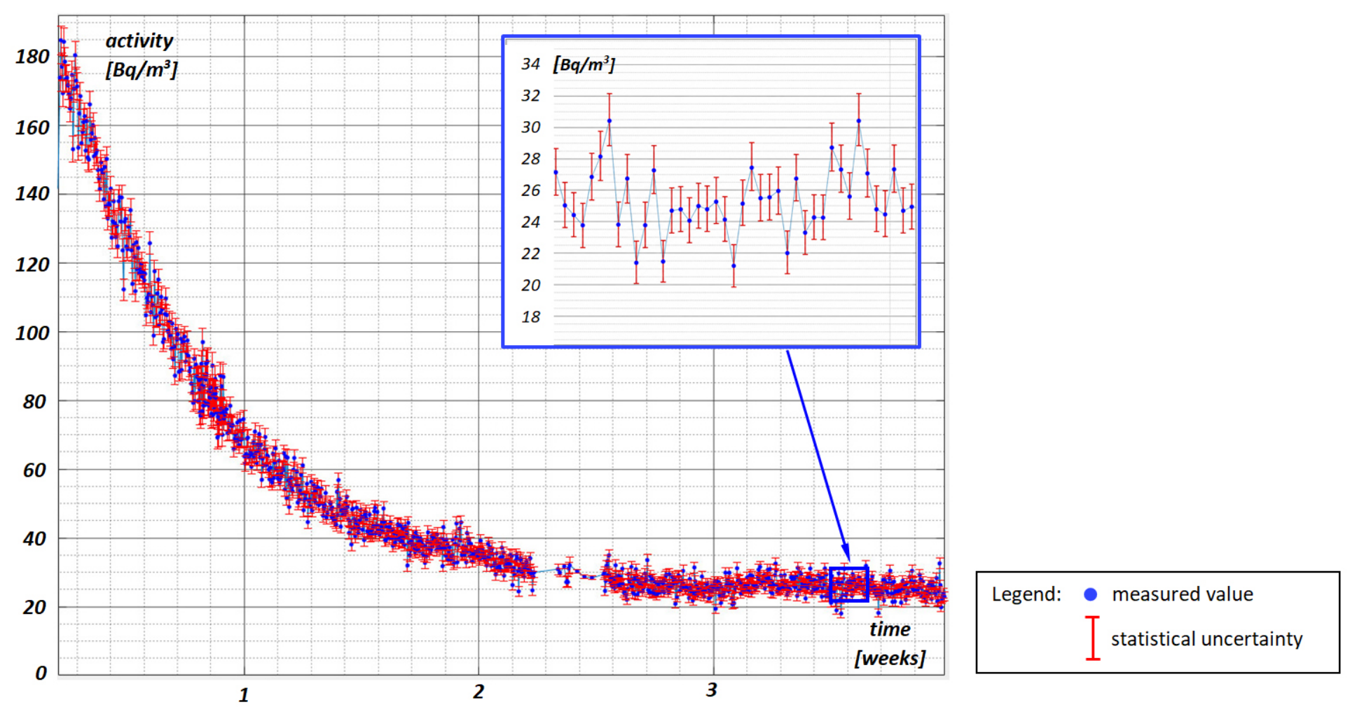
Additionally, a long-term measurement over several weeks was conducted using a
226Ra source. Here, the initial
222Rn concentration in the chamber was set to approximately
and the CIPIC was then sealed, cf. [
24]. The corresponding decay curve determined through measurements taken at 30 min intervals is shown in
Figure 8. A half-life of approximately 3.82 days (the known half-life of
222Rn ) is clearly visible.
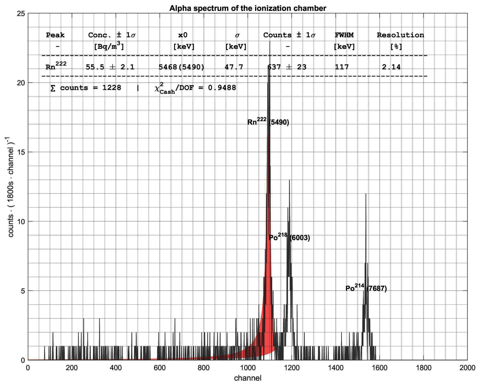
One of CIPIC’s periodic short-term measurements during continuous operation is shown as an example in
Figure 9. With 637 decays attributed to the
222Rn peak, this results in an efficiency of 90% and a resolution (relative FWHM) of 3.07%. This is exceptionally good.
These real-time results are confirmed by the calibration reported in [
21]. There, the CIPIC measurement error follows a Gaussian distribution with an FWHM of only about
for an ambient activity of less than
.
4. Summary
For significantly improved measurements of radon in ambient air, this paper presents a pulse-proportional ionization chamber. The detector, which is based on direct -decay detection, enables accurate measurement of low radon concentrations with an energy resolution of 2–3%.
This performance is enabled by the double-cylindrical design of the ionization chamber, which allows for highly efficient, nearly complete detection of particles by eliminating obstacles in the drift paths of the ionized charge carriers. The generated charges are strictly proportional to the particle energy and can be processed with an efficiency of 90%. Further, we developed an adapted spectroscopic measurement method that reliably discriminates between the contributions of 222Rn, 218Po, and 214Po, thereby allowing for the precise determination of their individual concentrations. Additionally, an elaborated damping system minimizes acoustic and vibrational noise and enables a high energy resolution during detector operation.
Thanks to the excellent spectral resolution of the developed ionization chamber, very low 222Rn activity concentrations can be measured in a short time. The chambers with about 8 L of volume provide measurement uncertainties below 5% within 30 min intervals, for example in air with radon activity.
Compared to conventional scintillation counters, the developed pulse-proportional ionization chambers offer several advantages for radon monitoring. This enables direct decay detection in ambient air, achieving a superior energy resolution of about 2%. It also allows clear spectroscopic discrimination between 222Rn, 218Po, and 214Po which is often difficult with scintillation detectors.
In the future, our investigations will continue with detailed indoor and outdoor measurements, along with correlation to the ambient conditions.