1. Introduction
With the rapid expansion of high-speed railway networks worldwide, ensuring the operational safety of high-speed electric multiple units (EMUs) has become a major concern in railway engineering. Although modern EMUs exhibit excellent dynamic performance and operational efficiency, their safety under extreme conditions remains vulnerable to various factors, including track geometric irregularities, vehicle dynamic instability, infrastructure failures, earthquakes, and crosswind excitations [
1,
2]. Once derailment occurs, the vehicle may experience severe lateral displacement, excessive yaw and roll motions, vehicle separation, or even rollover, resulting in significant economic losses and casualties [
3,
4]. Consequently, understanding the dynamic evolution of derailment events and developing effective derailment containment strategies are essential for improving railway system safety.
The post-derailment behavior of railway vehicles is a highly nonlinear process involving complex interactions among vehicle components, track structures, and derailment protection devices. Accurate prediction of derailment evolution requires simultaneous consideration of multibody vehicle dynamics, nonlinear contact mechanics, impact behavior, and track geometric characteristics [
5]. In recent years, considerable efforts have been devoted to developing derailment dynamics models and investigating derailment containment mechanisms. Santelia et al. [
6,
7] developed multibody nonlinear dynamic models to simulate the contact and impact interactions between derailed railway vehicles and infrastructure components. Their studies demonstrated that accurate representation of multi-point contact forces is essential for predicting derailment loads and vehicle trajectories. By coupling multibody vehicle models with finite element models of derailment containment structures, they further showed that simplified yet computationally efficient contact formulations can still provide reliable predictions when compared with experimental derailment data. Similarly, Tanabe et al. [
8] and Pogorelov et al. [
9] proposed advanced derailment simulation approaches capable of reproducing complex derailment processes under earthquake excitation and longitudinal train dynamics conditions. Shi et al. [
10] established a derailment dynamics model considering seismic excitation, vehicle–track interaction, and three-dimensional multi-point nonlinear contacts, and systematically analyzed the derailment evolution of high-speed EMUs under different operating speeds and earthquake intensities.
To improve the understanding of post-derailment vehicle behavior, Tang et al. [
11] systematically reviewed derailment dynamics, contact-impact modeling methods, and derailment containment technologies. They subsequently proposed a Polygon Contact Model (PCM)-based derailment dynamics framework, which significantly improved computational efficiency while maintaining prediction accuracy for complex contact interactions between railway vehicles and track structures. These studies have established an important foundation for investigating derailment containment mechanisms using numerical approaches. Besides derailment modeling, researchers have also investigated the influence of vehicle dynamic characteristics and external excitations on derailment safety. Torun and Erol [
12] analyzed the trade-off between ride comfort and derailment safety through suspension parameter optimization. Zhu et al. [
13] proposed a derailment-risk-domain-based safety assessment method for high-speed trains subjected to seismic excitation. Lai et al. [
14] investigated derailment behavior in railway turnouts caused by track failures and demonstrated that geometric discontinuities and stiffness variations can significantly increase derailment risk and aggravate post-derailment instability.
More recently, increasing attention has been directed toward derailment containment and vehicle self-protection mechanisms. Wang et al. [
15] conducted full-scale derailment experiments and numerical simulations to investigate the protective effects of underframe equipment during derailment events, providing valuable experimental evidence regarding the limiting and energy-dissipation functions of vehicle components. Song et al. [
16] further emphasized the importance of track–vehicle contact interactions in turnout-related derailment scenarios. In engineering applications, various passive protection devices have been proposed to mitigate derailment consequences. For example, Guo et al. [
17] investigated the structural performance and failure modes of clamp-type anti-derailment devices for high-speed trains, while other studies explored novel derailment containment systems for complex railway infrastructures. These efforts demonstrate the growing interest in passive derailment protection technologies. In addition to derailment-specific investigations, operational reliability and safety enhancement strategies for modern passenger transportation systems have also attracted considerable attention [
18,
19].
Existing studies have primarily focused on wheel–rail contact failure mechanisms and post-derailment vehicle motion, whereas the coordinated protective effects of underframe self-protection structures and anti-yaw stoppers have received limited attention. Moreover, the interaction mechanisms among gearboxes, traction motors, brake discs, anti-yaw stoppers, and track structures during derailment remain insufficiently understood. Therefore, unlike previous studies that mainly focus on wheel–rail contact loss, derailment containment devices, or post-derailment vehicle motion separately, this study establishes a comprehensive derailment dynamics framework that simultaneously considers the interactions among wheelsets, brake discs, traction motors, gearboxes, anti-yaw stoppers, and track structures. The model can study the coordinated protection mechanism between the vehicle self-protection structure and anti-yaw stopper through multi-point nonlinear contact interaction. The proposed approach provides new insights into the coordinated anti-derailment mechanisms of passive protection devices and offers practical guidance for derailment containment design and safety assessment of high-speed railway vehicles.
2. Derailment Dynamic Model
2.1. Overall Modeling Framework
To systematically investigate the post-derailment dynamic behavior and derailment containment performance of high-speed electric multiple units (EMUs), the vehicle–track coupled dynamics models based on multibody dynamics theory is established. Unlike conventional vehicle dynamics models under normal wheel–rail contact conditions, where vehicle motion is primarily governed by Hertz wheel–rail interaction, the dynamic behavior after derailment is dominated by multi-point, nonlinear, and transient contact–impact interactions among various vehicle components. These components include wheels, brake discs, gearboxes, traction motors, and anti-yaw stoppers, which may simultaneously or sequentially come into contact with the track structures after the loss of wheel–rail constraint. Therefore, an accurate description of the geometric characteristics, relative positions, and connection constraints of these key components, as well as their multibody contact relationships with the track system, constitutes the core of derailment dynamics modeling.
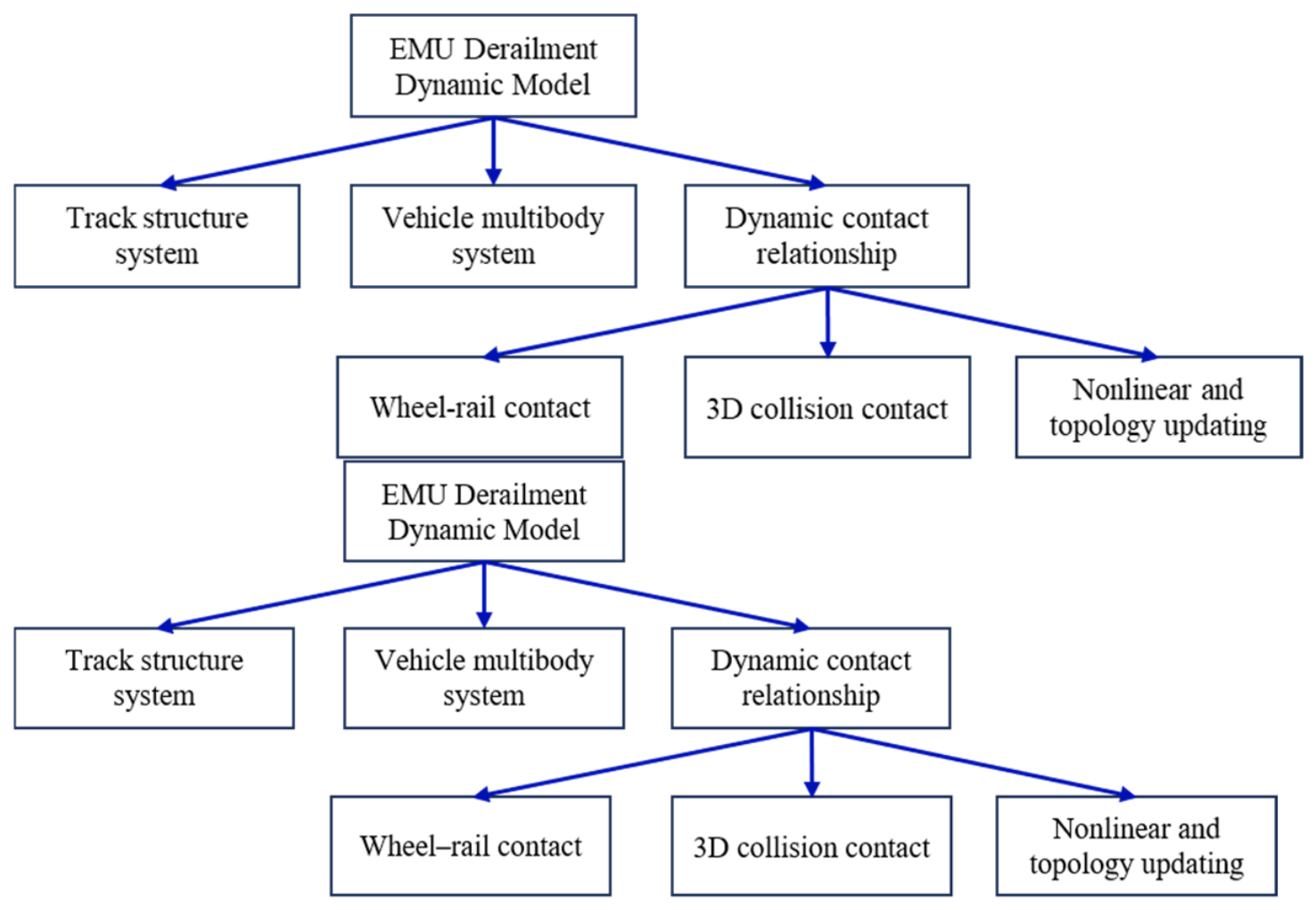
The commercial multibody dynamics software ADAMS/Rail v.2005 is employed as the simulation platform. As illustrated in
Figure 1, the entire system is divided into three main subsystems: the vehicle subsystem, the track subsystem, and the dynamic contact–interaction subsystem. All vehicle and track components are modeled as rigid bodies, while mechanical coupling between components is realized through contact elements. The dynamic contact formulation accounts for both the wheel–rail interaction prior to derailment and the three-dimensional (3D) collision contacts that may occur after derailment. Moreover, the strong nonlinearity and variable topology of contact conditions during the derailment process are explicitly considered. The resulting derailment dynamics model is capable of reproducing the transient dynamic response of the vehicle after derailment and enables quantitative evaluation of contact forces, energy dissipation, and their influence on vehicle attitude evolution and stability. This modeling framework provides a solid foundation for subsequent analyses of derailment response characteristics and the effectiveness of self-protection structures and anti-derailment devices.
The derailment dynamics model was established using ADAMS/Rail 2010, and the model parameters were derived from an actual high-speed EMU configuration. The simulated derailment evolution process was compared with published derailment test results and validated numerical studies, showing good agreement in terms of wheelset displacement evolution and vehicle attitude development. It should be noted that the present investigation is primarily based on numerical simulations. Although the model has been verified using published derailment data, uncertainties associated with contact parameters, structural deformation, and impact damage may still influence the predicted responses.
2.2. High-Speed EMU Vehicle Modeling
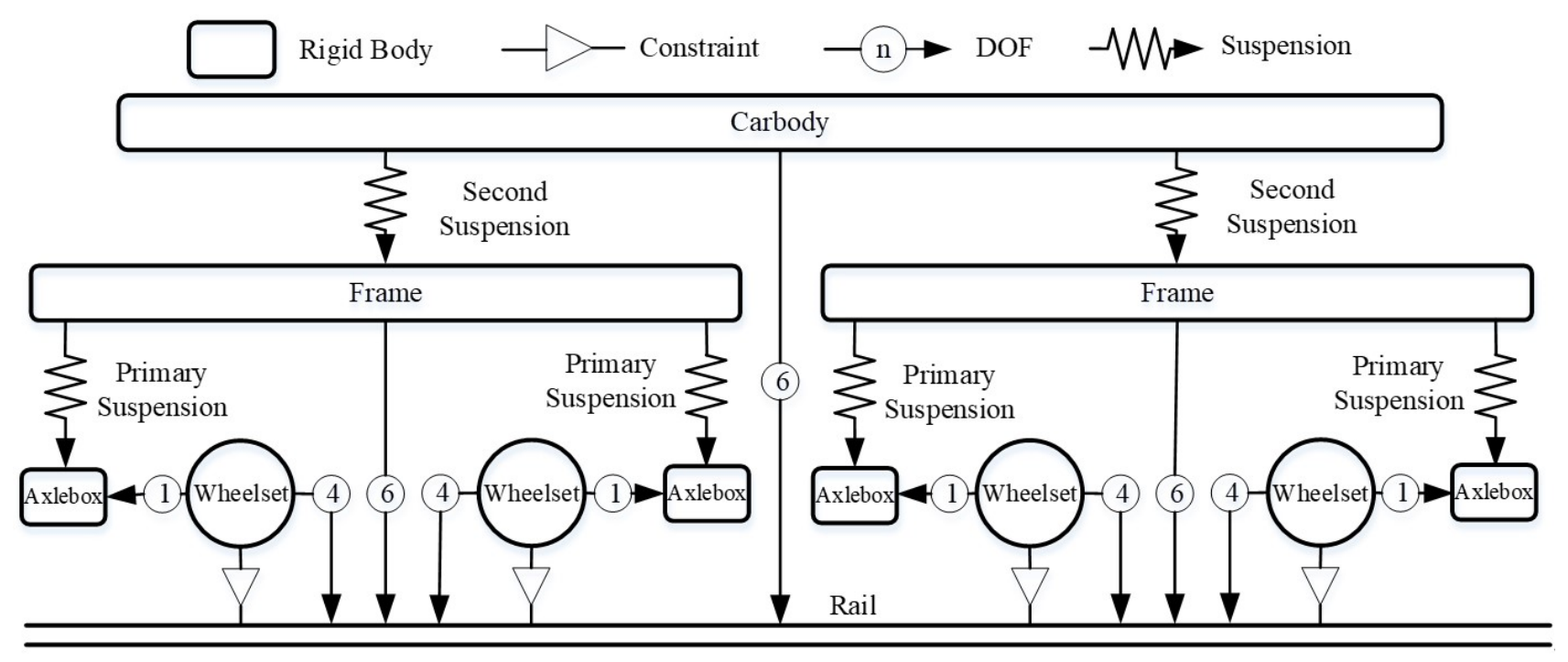
A refined multibody dynamics model of a high-speed EMU is established based on the actual vehicle configuration, including both a motor car model and a trailer car model. Each complete vehicle model consists of one carbody and two bogies. Each bogie comprises one frame, two wheelsets, four axleboxes, and the suspension system. In the motor car model, the powered bogie is additionally equipped with a traction transmission system composed of a gearbox and traction motor suspended beneath the bogie frame, whereas in the trailer car model, the non-powered bogie is fitted with brake discs mounted on the wheel axles. A topology diagram of the vehicle multi-body dynamic system is shown in
Figure 2, and the main dynamic parameters of the high-speed EMU are shown in
Table 1.
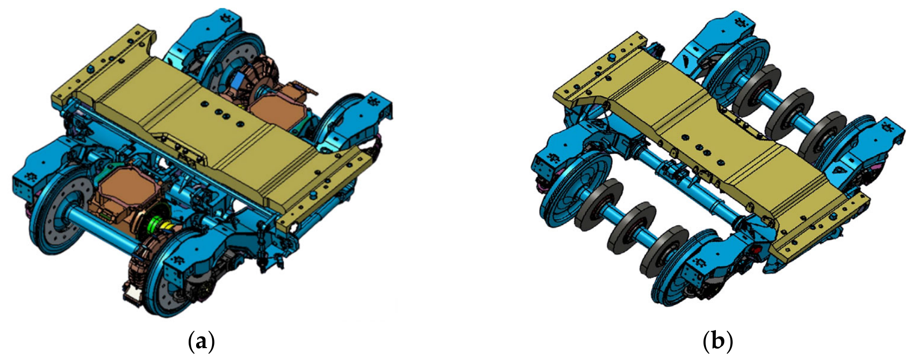
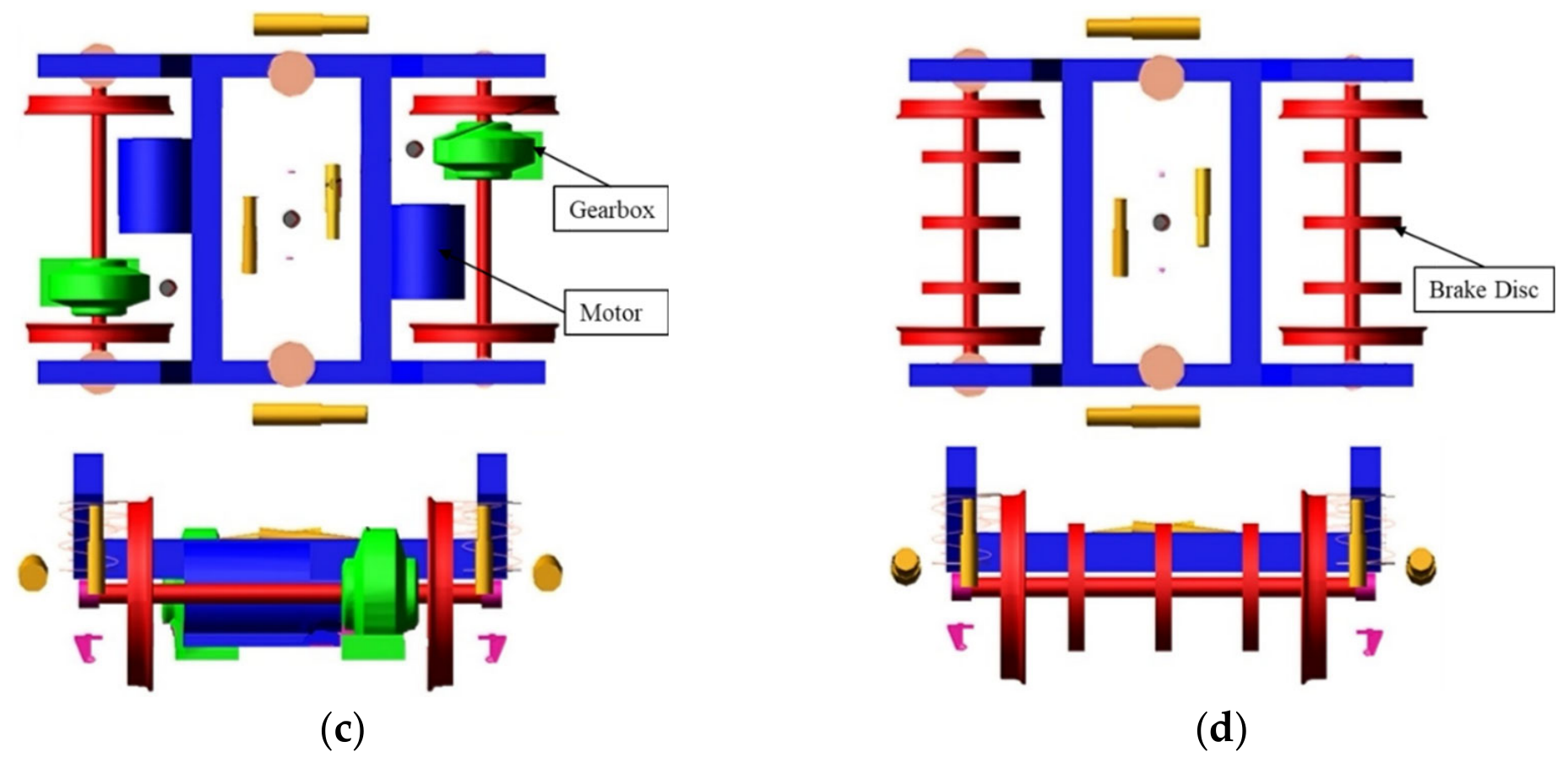
Underfloor equipment such as gearboxes, motors, and brake discs is characterized by complex geometry and highly concentrated mass, and these components are prone to collide with track structures after derailment. Consequently, they play a critical role in governing post-derailment dynamic behavior. To achieve a balance between modeling accuracy and computational efficiency, appropriate simplifications are introduced. The traction motor is simplified as an equivalent rigid cylinder rigidly attached to the bogie frame to preserve its mass and inertia properties. The gearbox is represented by its three-dimensional geometric model and treated as a dynamic rigid body; it is connected to the wheelset through a revolute joint at one end, while the other end is suspended from the bogie frame via a flexible support. The brake disc is simplified according to its outer contour and modeled as an integral part of the wheelset. In addition, both the primary and secondary suspension systems are modeled using linear spring–damper elements. In addition, lateral anti-yaw stoppers are arranged between the carbody and bogie frame to provide rigid limit constraints on relative motion.
Figure 3 illustrates 3D models of motor and trailer bogies, together with their corresponding derailment dynamics models.
In the multibody vehicle system model, key components such as the carbody, bogie frame, and wheelsets are all modeled as rigid bodies. Their actual geometric dimensions and mass distributions are preserved, and kinematic constraints between rigid bodies are realized through joints, elastic elements, and damping elements. Each carbody, bogie frame, and wheelset is assigned 6 DOFs, including longitudinal, lateral, and vertical translations, as well as yaw, pitch, and roll motions. The axlebox is simplified to possess a single rotational DOF corresponding to pitch motion about the axle. The traction motor is rigidly mounted on the bogie frame, the gearbox is connected to the wheelset axle and elastically supported by the frame, and the brake disc is treated as an integral part of the wheelset; these components are modeled as additional masses without independent DOF.
It should be emphasized that the motor bogie exhibits a significantly different mass distribution and center-of-gravity height compared with the trailer bogie due to the traction equipment (motors and gearboxes) and braking equipment (brake discs). By explicitly preserving these structural differences, the proposed model enables a direct comparison of derailment protection performance between motor and trailer configurations, providing a reliable basis for subsequent dynamic response analysis and performance evaluation under derailment conditions.
2.3. Track Structure Modeling
To analyze the collision and contact behavior between vehicle components and track structures after derailment, it is necessary to establish a complete track model that accurately represents the geometric characteristics of rails, fasteners, and a slab track. Based on typical high-speed railway infrastructure in China, the CRTS II slab ballastless track is adopted as the basic track structure in the simulations, in combination with CN60 rails and WJ8 fasteners.
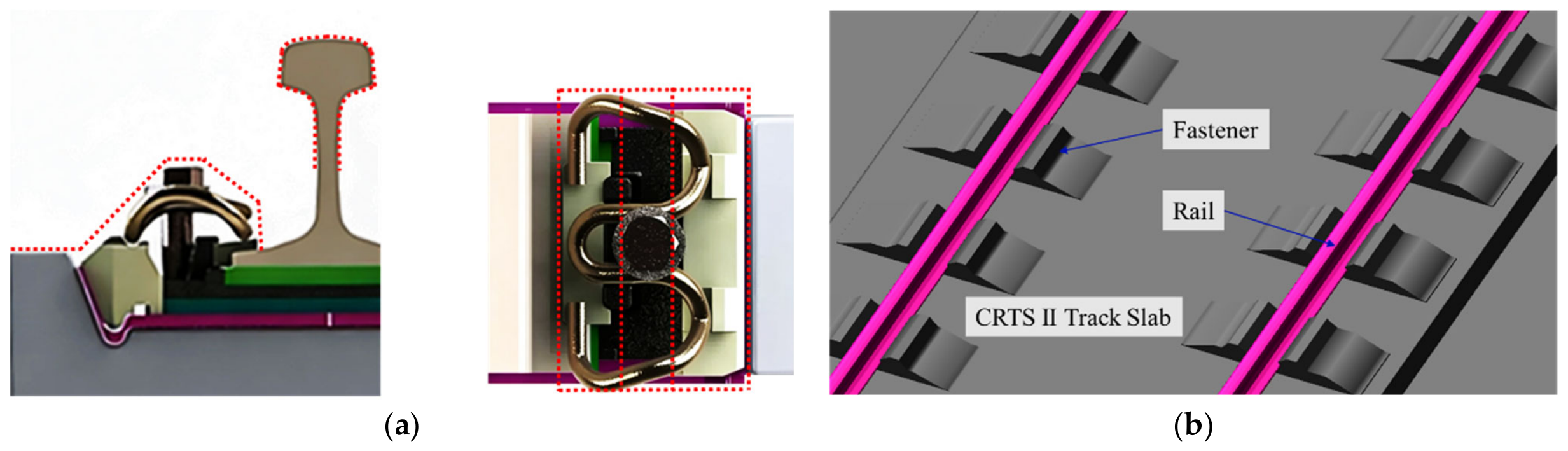
The CRTS II slab ballastless track was established using a customized modelling approach. Rails, fasteners, track slabs, and supporting layers were represented by equivalent spring–damper elements based on actual design parameters rather than predefined software templates. To simplify contact–impact calculations while ensuring computational efficiency and numerical stability, an appropriate level of geometric simplification is applied to the track components. Specifically, the track slab, which is characterized by large dimensions and high stiffness, is simplified as a planar structure while preserving its actual 3D geometry and equivalent mass properties. For geometrically complex components such as rails and fasteners, an envelope-based simplification strategy is employed, in which small-scale features, such as rubber pads and connecting bolts, are omitted while maintaining the essential external contours required for contact detection. This mainly removes local geometric details that have limited influence on large-scale post-derailment motion. Previous studies have shown that such simplifications primarily affect high-frequency local responses while having negligible influence on global derailment behavior. The simplification process for the WJ8 fastener is illustrated in
Figure 4a.
In the resulting track dynamics model, the fasteners are assumed to be rigidly connected to the track slab, whereas the rails are connected to the slab–fastener system through spring–damper elements, providing vertical, lateral, and longitudinal support stiffness and damping. And the main support stiffness and damping parameters are shown in
Table 2. The simplified track dynamic model obtained using this approach is shown in
Figure 4b. This modeling strategy effectively captures the rigid response of the slab track during post-derailment collisions while avoiding excessive structural complexity.
2.4. Dynamic Contact Modeling
After derailment, the normal wheel–rail contact relationship is lost and replaced by multibody collision contacts between key vehicle components and track structures. These contacts are highly stochastic and time-varying, and they play a decisive role in governing the post-derailment dynamic behavior of the vehicle, particularly the lateral displacement and stability, which are critical for evaluating derailment containment performance. Therefore, in addition to conventional wheel–rail Hertz contact, the model must account for all potential collision contact scenarios that may occur after derailment. In the present study, Hertzian nonlinear spring elements are adopted to describe the dynamic contact behavior between vehicle components and track. Meanwhile local structural deformation and material damage are not explicitly considered in structures. These simplifications may affect the prediction of local impact forces but are expected to have limited influence on the global derailment trajectory and vehicle attitude evolution investigated in this study.
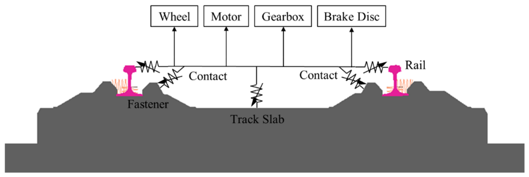
Due to the unstable posture of the vehicle following derailment, multiple forms of random collisions may occur between the vehicle and track structures. The geometric dimensions and installation clearances of the gearbox, traction motor, brake disc, and anti-yaw stopper were established according to the actual vehicle design drawings. The contact initiation conditions and limiting displacements were verified using the corresponding design specifications to ensure the accuracy of contact relationships during derailment. Based on the possible contact objects after derailment, a dynamic contact topology is established, as shown in
Figure 5. The contact topology includes wheelset–track contacts, which are used to simulate collisions between wheels and rails, fasteners, and slab track surfaces, and contacts between underfloor components, such as motors, gearboxes, and brake discs, and various track components. During vehicle roll and lateral motion, the relative spatial positions of these underfloor components change continuously, which may lead to geometric interference and subsequent collision contact with the track structures.
The dynamic behavior of the vehicle–track coupling system is governed by the multibody dynamic equation:
where
,
, and
denote the mass, damping, and stiffness matrices, respectively;
represents the generalized coordinate vector;
is the external excitation vector; and
denotes the nonlinear contact force vector.
All collision contact elements are formulated based on the Hertzian nonlinear spring model. The normal contact force between contacting bodies is calculated using a nonlinear elastic contact formulation:
where
is the equivalent contact stiffness, and
is the local deformation (penetration depth) between the contacting bodies.
The tangential friction during contact is modeled using the Coulomb friction law, with the friction coefficient
taken as 0.3 in this study with the tangential friction force given by:
Considering that contact conditions during derailment evolve rapidly over time, a penalty-based contact algorithm is employed to dynamically compute the normal and tangential forces and to enforce contact constraints. This approach allows smooth transitions between non-contact, contact, and separation states at each contact interface. All contact forces are solved using time-stepping integration, enabling the extraction of key response metrics such as impact force time histories, peak contact forces, and contact duration.
The vehicle–track derailment dynamics model employed in this study was developed on the basis of a validated high-speed EMU multibody dynamics framework. The vehicle dynamic responses under normal operating conditions, wheel–rail contact characteristics, and post-derailment motion trends were compared with published derailment test results and previous numerical investigations. The comparison confirmed that the model can reasonably reproduce the evolution of vehicle attitude and wheelset displacement during derailment, thereby providing a reliable basis for subsequent anti-derailment performance analysis.
3. Self-Protection Analysis of Vehicle Structures
Static geometric clearance checks conducted after vehicle derailment indicate that large underfloor components mounted beneath the bogie, such as brake discs, traction motors, and gearboxes, are the first elements to come into contact with the track structure once wheel–rail constraints are lost. These components therefore constitute the most fundamental and direct self-protection system of a high-speed EMU during derailment. Their geometric dimensions, installation positions, and structural stiffness determine the distribution of initial support points after derailment and directly influence vehicle roll angle, lateral displacement, and center-of-gravity migration, all of which are critical to post-derailment attitude stability. Focusing on the distinct structural characteristics of a motor car and trailer car, this section combines dynamic simulation and geometric verification to analyze the self-protection effects of key underfloor components and further examines the role of anti-yaw stoppers in constraining relative motion between the carbody and bogie frame.
Figure 6 shows the derailment simulation analysis model of vehicle-track coupling; the wheelsets are numbered in sequence from front bogie to rear bogie for clarity. In the simulations, the vehicle travels at an initial speed of 40 km/h and derails following an imposed disturbance. A time step of 1 × 10
−4 s and a total simulation duration of 6 s are adopted to fully capture transient dynamic responses and impact load evolution during the derailment process.
3.1. Effects of Motor and Gearbox
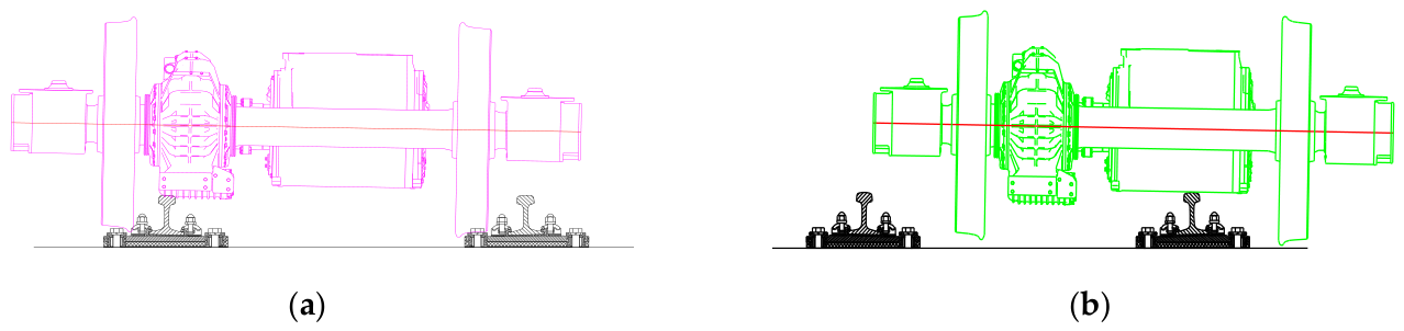
Powered bogies are equipped with large and stiff traction gearboxes and motors, whose geometric center is approximately 230 mm above the rail level. Under derailment-induced roll conditions, these components are more likely to collide with track structures. Based on static geometric clearance checks of vehicle and track configuration,
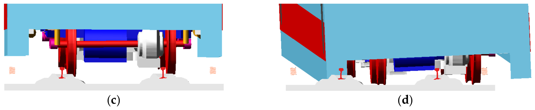
Figure 7a,b illustrate the typical protective postures of the gearbox and motor during the initial derailment stage. Correspondingly,
Figure 7c,d present the dynamic simulation results of gearbox–track and motor–track contact after derailment, with emphasis on the front bogie.
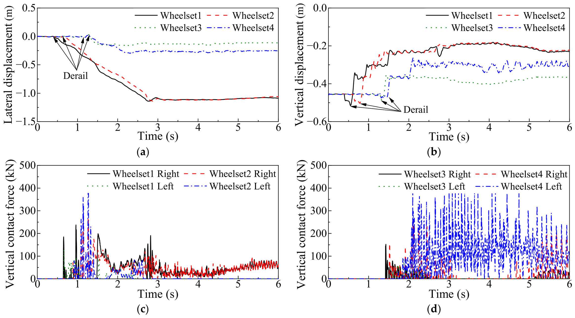
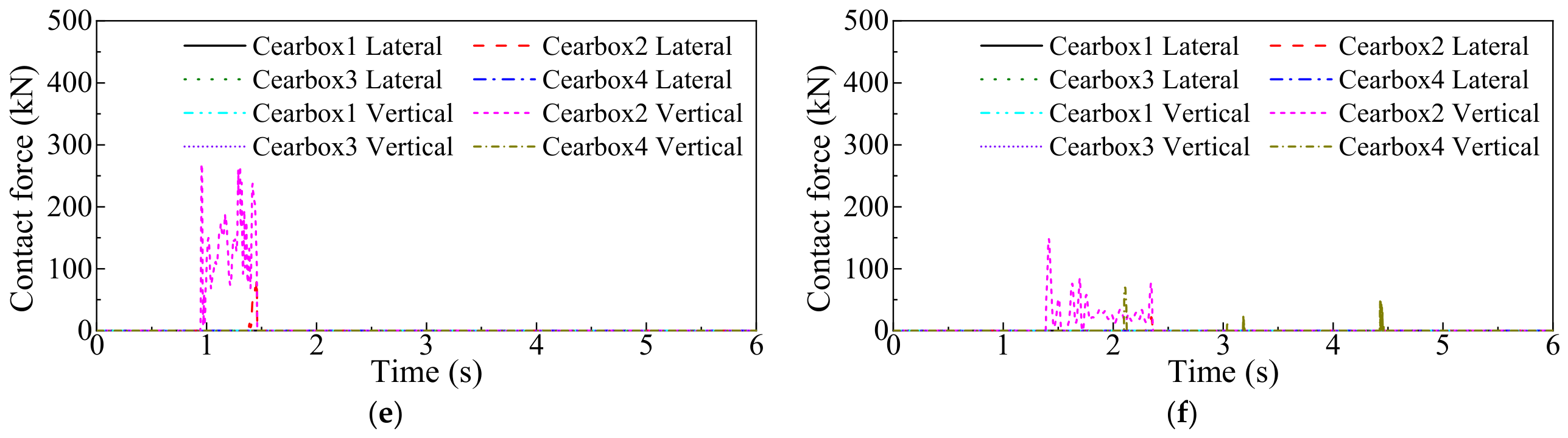
Figure 8 presents the dynamic responses of the motor car during derailment, including lateral and vertical wheelset displacements, vertical contact forces between wheels and the slab track, and lateral and vertical contact forces between the gearbox/motor and track. For derailment analysis, wheelset displacement is a direct indicator of transition from normal operation to derailment and subsequent post-derailment motion. As shown in
Figure 8a,b, the lateral and vertical displacements of four wheelsets evolve distinctly during the simulation.
Figure 8c,d illustrate the vertical contact forces between the left and right wheels of each wheelset and slab track.
The results show that the first and second wheelsets of the front bogie begin to climb the rail at approximately 0.4 s and 0.6 s, respectively, and derail about 0.2 s later. Following derailment, their displacements increase sharply and contact with the slab track occurs, including fastener regions, leading to sustained impacts as the vehicle continues to run over the slab. The derailment of the rear bogie lags behind that of the front bogie by approximately 0.8 s. As the vehicle advances, the lateral displacement of the front bogie wheelsets exceeds 1 m, whereas the wheelsets of the rear bogie remain within about 0.25 m. However, due to the presence of fastener structures on the slab track, their vertical displacement and contact force histories exhibit pronounced periodic fluctuations, particularly for the fourth wheelset.
At approximately 1.0 s, the lower surface of the gearbox first contacts the track structure, and both lateral and vertical contact forces rise rapidly. Owing to the derailment direction and gearbox geometry, the interaction is dominated by the second gearbox contacting the rail, while the other gearboxes exhibit negligible contact. The maximum lateral and vertical impact forces reach approximately 83.56 kN and 306.45 kN, respectively, and persist until about 1.5 s, as shown in
Figure 8e. This sustained collision between the gearbox and track partially restrains the vehicle’s lateral displacement and dissipates derailment kinetic energy through friction until the gearbox passes over the rail and loses its protective function. As the gearbox–track interaction diminishes, the vehicle slides down into the fastener region, and at approximately 1.4 s the traction motor begins to contact the track, again primarily involving the second motor, as illustrated in
Figure 8f. Once contact occurs, the motor remains pressed against the rail for an extended duration. The prolonged frictional interaction further restricts lateral displacement growth, although the contact force amplitudes are relatively smaller, with peak lateral and vertical forces of about 21.86 kN and 148.31 kN, respectively.
Overall, after derailment the wheelset displacements increase rapidly, while the gearbox and traction motor of the motor car engage in repeated collisions with the track during the early derailment stage. These interactions contribute to partial energy dissipation and provide some restraint against excessive lateral displacement. However, although the gearbox and motor exhibit a certain degree of derailment containment capability, their overall effectiveness in preventing further derailment development is limited.
3.2. Effect of Brake Discs
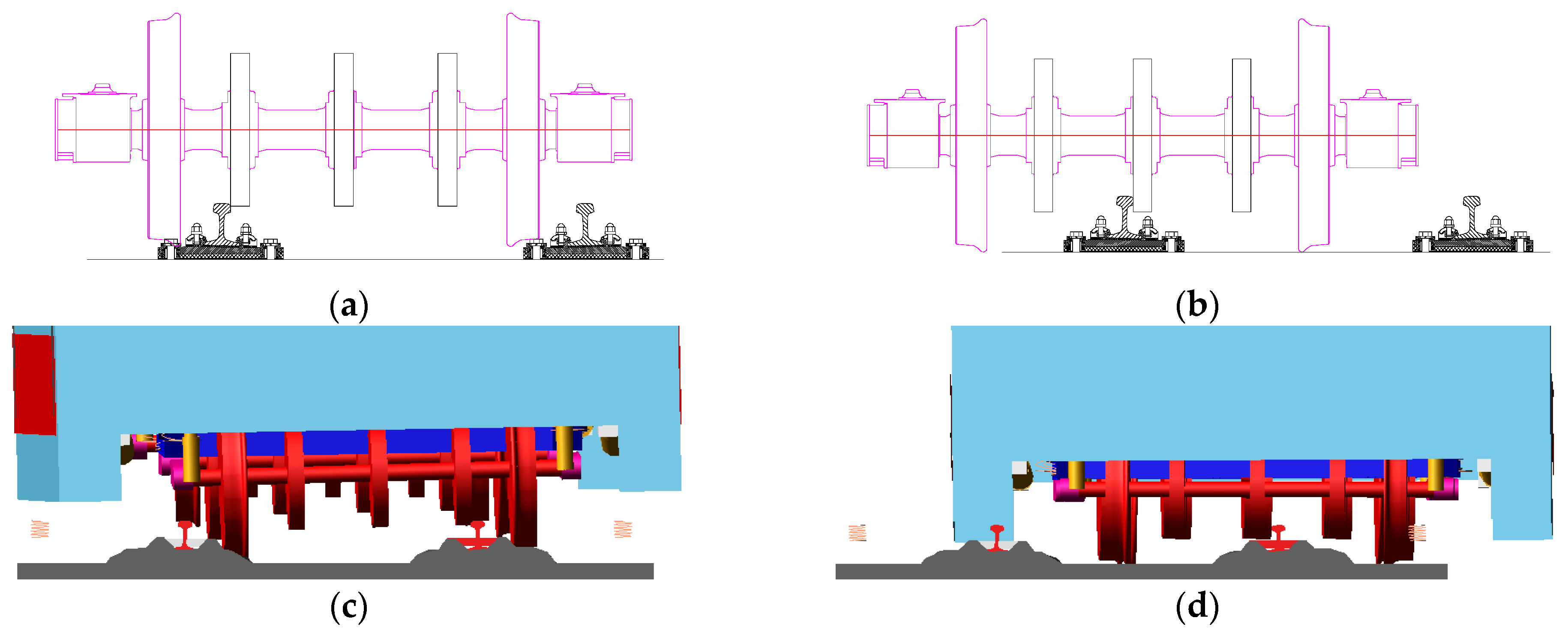
The trailer bogie is equipped with symmetrically arranged brake discs mounted on the wheelsets. The lower edge of the brake disc is located only about 45 mm above the rail top, which enables rapid collision contact with the track structure once derailment occurs. Owing to geometric interference caused by lateral vehicle displacement, not only the two outer brake discs but also the middle brake disc may come into contact with the rail.
Figure 9a,b present the contact postures between the brake discs and track structure obtained from static geometric clearance checks. Under the same initial speed of 40 km/h, derailment dynamics simulations are carried out for the trailer car, and the contact configurations of brake discs with the track structure after derailment are shown in
Figure 9c,d.
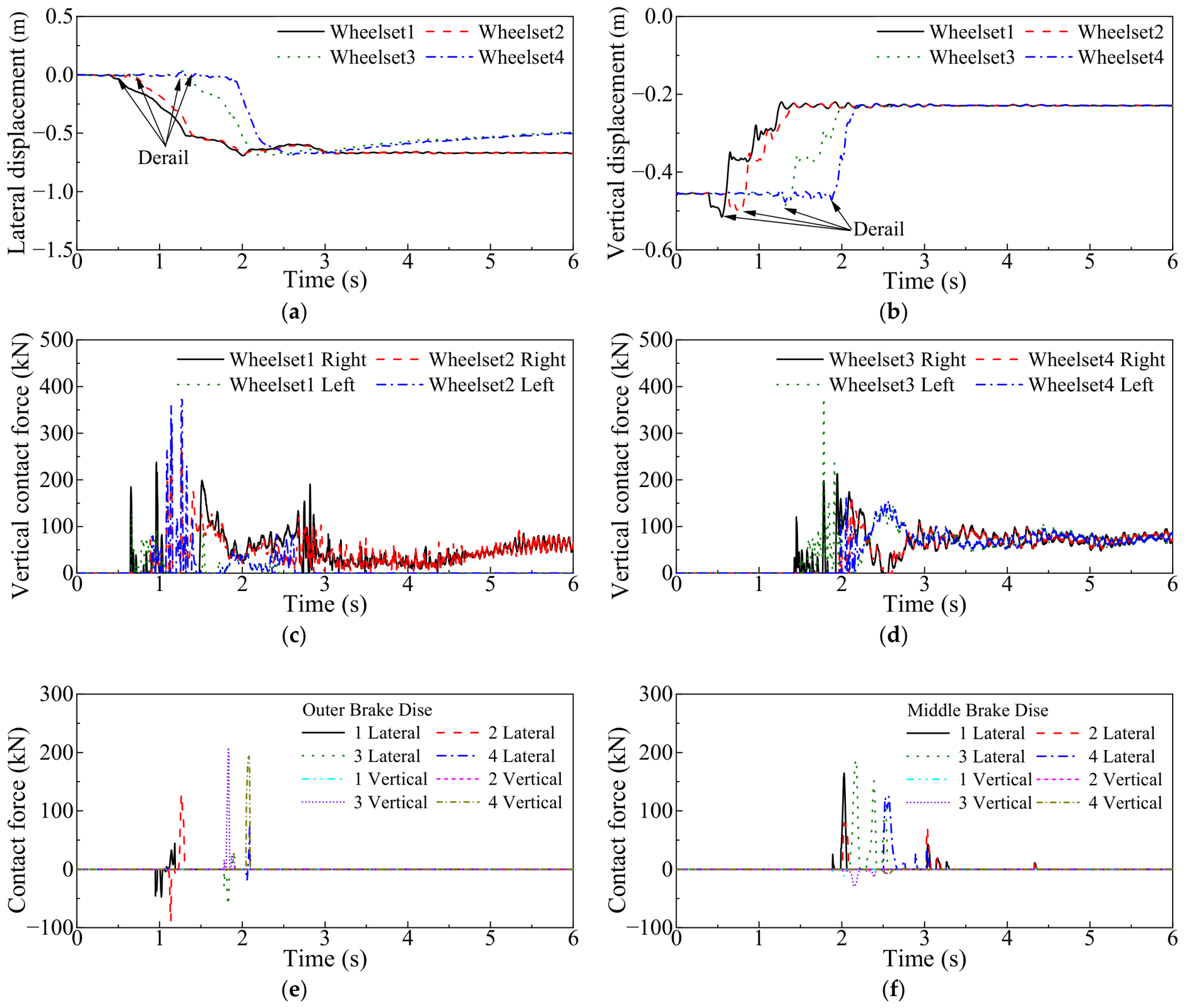
Figure 10 presents the dynamic responses of the trailer car during the derailment process, including wheelset displacements, vertical wheel–slab contact forces, and contact forces between the brake discs and the rail.
Figure 10a–d show the lateral and vertical displacements of the wheelsets together with the corresponding vertical wheel–slab contact forces. Following the loss of wheel–rail guidance, the leading and rear bogies derail at approximately 0.6 s and 1.4 s, respectively, resulting in repeated impacts between the wheelsets and the slab track. As the derailment progresses and the lateral displacement of the vehicle increases, the outer brake disc of the leading bogie comes into contact with the rail at approximately 0.9 s and remains engaged until about 1.4 s. During this period, the maximum lateral and vertical contact forces reach 128.01 kN and 208.40 kN, respectively. These results indicate that the brake disc provides an effective auxiliary restraint mechanism by limiting the lateral movement of the wheelsets and dissipating impact energy through continuous contact with the rail. However, as the vehicle continues to advance and repeatedly interacts with the fastener region, the brake disc is subjected to increasingly severe lateral impact loads. Once the brake disc passes over the rail, the contact constraint is lost, leading to a rapid increase in wheelset lateral displacement and a consequent reduction in derailment containment capability.
At approximately 1.9 s, after the vehicle slides down from the fastener region, the middle brake disc begins to contact the rail and remains in contact until about 3.4 s. The maximum lateral and vertical contact forces acting on the middle brake disc are approximately 187.70 kN and 28.73 kN, respectively. In this stage, the contact force is dominated by its lateral component, which effectively restrains further lateral displacement of wheelsets and prevents excessive motion of the carbody and bogie frame. Acting as a substitute for the outer brake disc, the middle brake disc plays a dominant role in preventing further derailment, with the wheelset lateral displacement remaining within approximately 0.75 m.
The simulation results of the motor car and trailer car are further compared to evaluate the dynamic responses and protection effectiveness of two bogie configurations under derailment conditions. The lateral wheelset displacement results clearly indicate that, owing to their low installation position and rigid connection to the axle, brake discs provide rapid support immediately after derailment and effectively suppress excessive lateral displacement. The sustained limiting and energy-dissipation effects of both the outer and middle brake discs result in significantly smaller lateral deviations compared with those observed for the motor car. In contrast, the motor car, which is equipped with high-mass and high-stiffness components such as traction motors and gearboxes, experiences more severe collisions with the track after derailment, with peak contact forces generally 20–30% higher than those of the trailer car. These findings demonstrate that brake discs provide superior derailment containment performance compared with traction motors and gearboxes, and that the trailer car exhibits a more favorable structural configuration for post-derailment protection.
4. Analysis of Anti-Yaw Stopper Effect
4.1. Configuration of Anti-Yaw Stoppers
Extensive derailment accident investigations and previous studies have demonstrated that excessive relative yaw motion between the carbody and bogie after derailment is one of the primary factors leading to accident escalation, as it promotes lateral instability, wheelset divergence, and vehicle rollover [
7,
11]. Once derailment occurs, the wheel–rail constraint rapidly vanishes, and the bogie undergoes significant rotation under inertial forces and lateral impacts. If the relative yaw angle between the carbody and bogie is not effectively restrained, the vehicle will be unable to maintain motion along the track direction. Excessive yaw motion may induce relative buckling between adjacent car bodies and can also cause failure of the coupler system under large angular deviations, ultimately resulting in train separation and a substantial aggravation of derailment consequences.
To suppress excessive relative yaw motion during derailment and to enhance post-derailment attitude stability, anti-yaw stoppers are installed between the carbody and bogie. The anti-yaw stopper is a critical passive protection component connecting the carbody and bogie. By providing lateral limiting constraints under abnormal operating conditions, it effectively restricts the growth of relative yaw angles between the carbody and frame, enabling the derailed vehicle to maintain sliding motion along the track direction for a certain period and thereby reducing the risks of rollover and train separation.
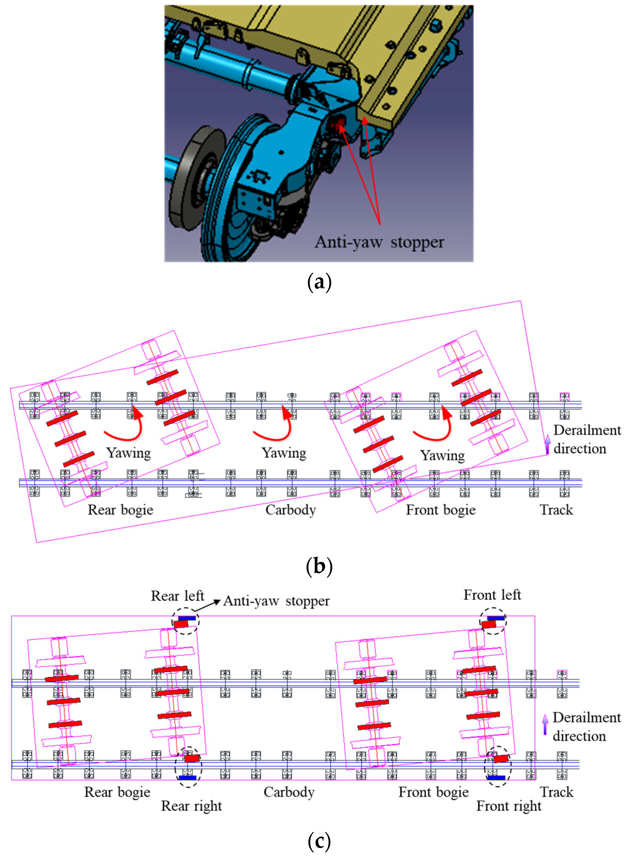
In the established EMU derailment dynamics model, anti-yaw stoppers are arranged at corresponding positions between the carbody and bogie and are equivalently modeled as paired lateral limiting structures, as illustrated in
Figure 11a. Their geometric locations, installation clearances, and mechanical parameters are determined according to the actual EMU structural layout.
Figure 11b,c show derailment configurations of the trailer car without and with anti-yaw stoppers, respectively. Under normal operating conditions, the anti-yaw stoppers remain inactive and do not participate in load transfer. Only when the relative yaw angle or lateral displacement between the carbody and bogie exceeds the predefined clearance does the stopper engage and generate a restoring force, thereby introducing pronounced nonlinear limiting behavior.
In the dynamic model, the anti-yaw stoppers are represented using nonlinear contact elements. The equivalent contact stiffness is set to 4 × 10⁶ N/m, which provides sufficient limiting capability while avoiding excessive stiffness that could amplify high-frequency impact loads. This choice ensures a balance between numerical stability and engineering realism. The initial clearance of stoppers is defined based on vehicle structural design parameters, so that they are activated only under derailment or large abnormal attitude conditions, thereby preventing adverse effects on vehicle dynamic performance during normal operation. Although the configuration of anti-yaw stoppers is identical for motor cars and trailer cars, their actual protective effectiveness differs significantly due to variations in the self-protection capability of underfloor structures mounted on the respective bogies.
4.2. Dynamic Response Analysis
Based on the established vehicle–track derailment dynamics model, the dynamic role of anti-yaw stoppers in restraining the relative yaw motion between the carbody and bogie is systematically analyzed for both motor-car and trailer-car configurations.
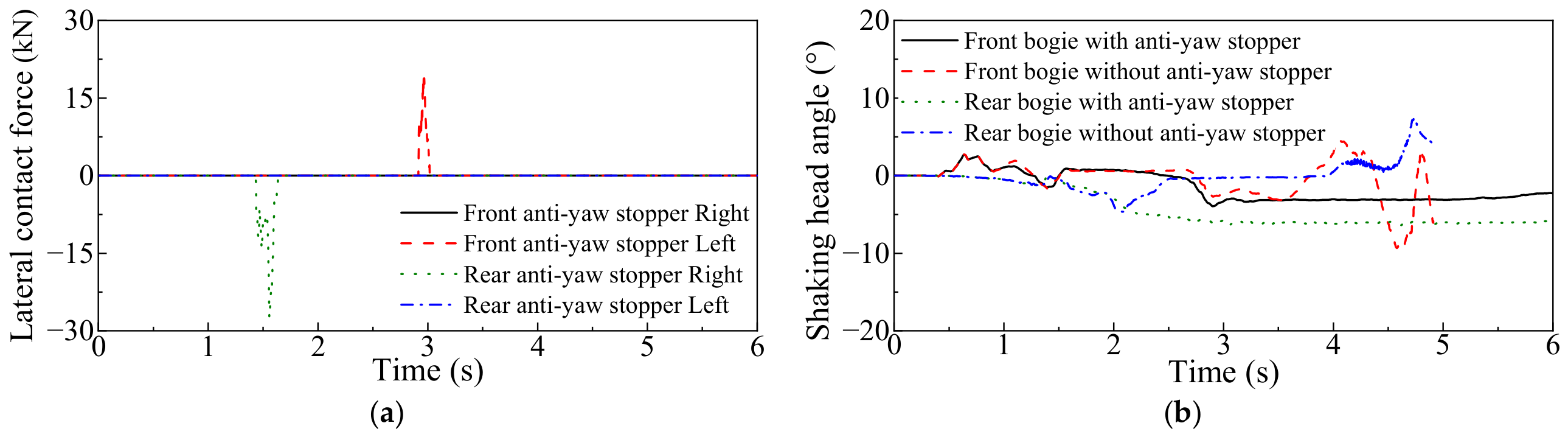
Figure 12 presents the time histories of lateral contact forces of anti-yaw stoppers, and the relative yaw angles between the carbody and bogie under derailment conditions at an operating speed of 40 km/h.
For the motor car, when anti-yaw stoppers are installed between the carbody and bogie, the stoppers are activated during two distinct periods, approximately 1.4–1.6 s and 2.9–3.0 s, as shown in
Figure 12a. The corresponding peak lateral contact forces reach 27.8 kN and 19.4 kN, respectively, indicating that the anti-yaw stoppers provide effective lateral constraints once the relative displacement exceeds the predefined clearance. As a result, excessive relative motion between the carbody and bogie is suppressed during the derailment process.
Figure 12b compares the relative yaw angles of the leading and rear bogies with and without anti-yaw stoppers. Without anti-yaw stoppers, the relative yaw angles increase rapidly following derailment and exhibit pronounced oscillatory behavior. The maximum yaw angles of the leading and rear bogies reach −9.3° and 7.4°, respectively, indicating severe post-derailment instability. Excessive yaw motion alters the load transfer path between the carbody and bogie, promotes lateral attitude divergence, and increases the risk of rollover or further derailment development. In contrast, when anti-yaw stoppers are installed, contact is initiated at approximately 1.4 s, and the resulting nonlinear constraint forces effectively limit the growth of relative yaw motion. Consequently, the peak yaw angles of the leading and rear bogies are reduced to −6.2° and −4.0°, corresponding to reductions of approximately 33% and 46%, respectively, while the associated oscillations are significantly attenuated.
Combined with the wheelset lateral displacement responses, the results demonstrate that the anti-yaw stoppers not only restrict relative carbody–bogie rotation but also indirectly suppress lateral wheelset migration after derailment. This coordinated constraint mechanism helps maintain a more stable post-derailment vehicle attitude and enables the vehicle to continue sliding along the track direction without pronounced rollover instability. Therefore, the anti-yaw stopper acts as a critical secondary protection device that mitigates derailment progression and substantially improves the post-derailment stability of the motor car, which is consistent with the derailment containment mechanisms reported in previous studies [
7,
13].
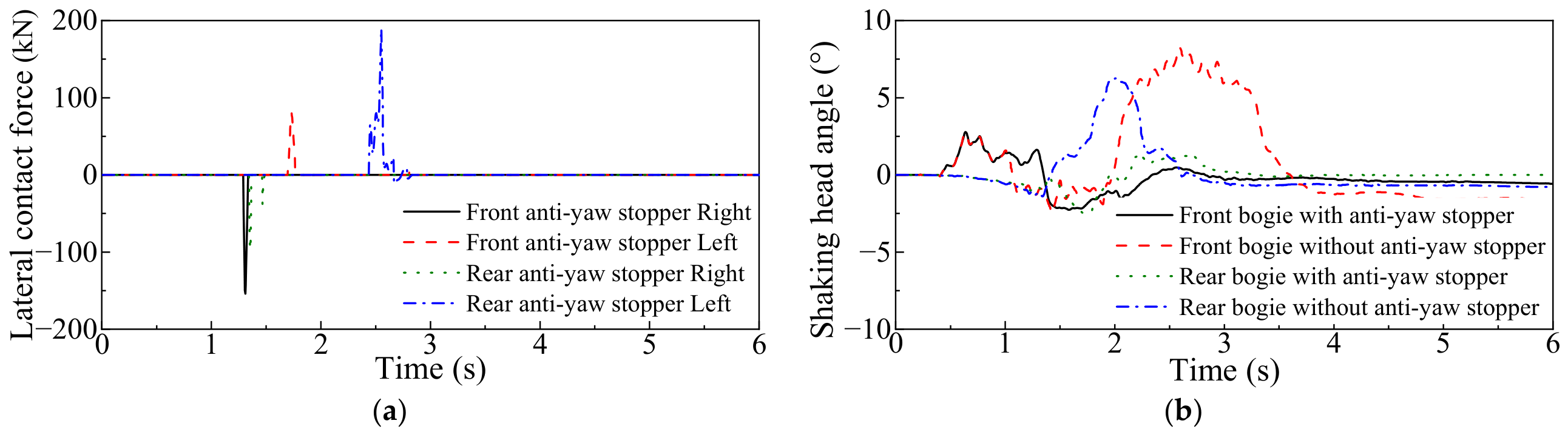
For the trailer car, the anti-yaw stoppers at different positions engage sequentially after derailment and generate substantially larger contact forces, with peak values reaching up to 190 kN, as shown in
Figure 13a. Analysis of corresponding relative yaw angles between the carbody and bogie, presented in
Figure 13b, indicates that without anti-yaw stoppers the relative yaw angles of the leading and rear bogies can reach 8.2° and 6.2°, respectively. Such large yaw motions significantly increase the likelihood of further derailment development or rollover instability. When anti-yaw stoppers are installed, their effective constraint on relative carbody–bogie motion markedly reduces the yaw-angle peaks, with reductions of approximately 70% for the front bogie and 63% for the rear bogie. In this case, the relative yaw angles remain within about 2.5°, which is consistent with the observed limitation of wheelset lateral displacement and leads to improved running stability during derailment.
Overall, the simulation results clearly indicate that, for both motor and trailer cars, the relative yaw angles without anti-yaw stoppers are significantly larger than those obtained with anti-yaw stoppers, making the vehicle more prone to derailment escalation and rollover. A further comparison between the motor-car and trailer-car results shows that the difference in yaw response with and without anti-yaw stoppers is more pronounced for the trailer car. This behavior can be attributed to the superior self-protection capability provided by the brake discs on the trailer bogie, which, when combined with anti-yaw stoppers, more effectively restrict lateral displacement and suppress attitude divergence. These findings confirm that the coordinated action of underfloor self-protection structures and anti-yaw stoppers is essential for enhancing derailment containment performance.
5. Discussion
The derailment process of a high-speed electric multiple unit is governed by complex nonlinear contact interactions between vehicle components and track structures after wheel–rail separation [
20,
21,
22]. The simulation results indicate that underframe components, including gearboxes, traction motors, and brake discs, are the first elements to contact the track and therefore play a critical role in the initial containment of derailment motion.
Different underframe components exhibit distinct protective mechanisms. For the motor car, the gearbox and traction motor provide temporary lateral restraint through impact contact, but their effectiveness decreases rapidly due to the short contact duration [
23,
24,
25]. In contrast, the brake discs of the trailer car establish earlier and more stable contact with the track owing to their lower installation position and symmetric configuration, resulting in improved energy dissipation and more effective control of lateral displacement. Similar self-protection effects of underframe equipment have been reported in previous derailment studies [
10,
15]. The anti-yaw stopper serves a complementary function by restricting the relative yaw motion between the carbody and bogie. The results show that the installation of anti-yaw stoppers reduces the peak yaw angle by approximately 30–70%, thereby suppressing posture divergence and mitigating the risk of rollover or derailment escalation. This finding is consistent with previous investigations on derailment containment mechanisms [
6,
7].
A coordinated protection mechanism is therefore observed. Underframe components provide initial support and displacement restraint immediately after derailment, while the anti-yaw stopper subsequently limits relative yaw motion. The combined action of these passive protection devices significantly reduces lateral displacement, roll motion, and yaw instability, improving the overall derailment containment capability of high-speed EMUs. It should be noted that the present model assumes rigid track structures and neglects component damage during impact [
26,
27,
28]. Future work will incorporate track flexibility, structural failure behavior, and experimental validation to further improve the accuracy and engineering applicability of the proposed derailment dynamics framework.