Article

Mechanical Behavior and Fracture Mechanism of Phyllite with Different Foliation Angles Under Uniaxial Compression


1
Jiangxi Provincial Key Laboratory of Safe and Efficient Mining of Rare Metal Resources, Ganzhou 341000, China
2
School of Mining Engineering, Jiangxi University of Science and Technology, Ganzhou 341000, China
3
Sinosteel Maanshan Institute of Mining Research Co., Ltd., Maanshan 243000, China
4
Changsha Institute of Mining Research Co., Ltd., Changsha 410012, China
*
Authors to whom correspondence should be addressed.
Appl. Sci. 2026, 16(17), 8525; https://doi.org/10.3390/app16178525
Submission received: 29 July 2026 / Revised: 18 August 2026 / Accepted: 22 August 2026 / Published: 27 August 2026

Abstract

Foliation-induced anisotropy in phyllite leads to complex deformation and failure responses, making excavation stability analysis and support design particularly challenging for geo-energy and geo-resource applications. To elucidate the influence of foliation angle (β) on mechanical behavior and fracture mechanisms, uniaxial compression tests were conducted and Particle Flow Code numerical simulations were performed on phyllite specimens with seven different foliation angles. The anisotropic mechanical behavior of phyllite under uniaxial compression was systematically analyzed across varying foliation angles. Furthermore, the interaction mechanism between matrix and foliation-induced cracks was investigated based on relevant theoretical frameworks. The foliation angle β has a significant effect on the stress–strain curve of phyllite. The elastic modulus generally increases with increasing β, whereas the peak strength displays an overall U-shaped distribution. As β increases, the macroscopic failure mode shifts from matrix-dominated fracturing to foliation plane-controlled slip/opening, and then trends back toward matrix-dominated fracturing at high β. In the simulations, microcrack type, initiation sequence, and the internal mechanism of instability vary markedly across β. Combined with the energy release rate criterion of fracture mechanics and the compression bar stability theory, the mutual induction mechanism between matrix cracks and foliation cracks is further clarified. The penetration or deflection behavior of matrix cracks near weak planes is jointly controlled by the crack propagation direction and foliation angle. When the foliation plane is parallel to the loading direction, the buckling instability of thin rock flakes resulting from tensile cracking along weak planes constitutes the primary factor contributing to the reduction in the strength of specimens where the foliation plane is normal to the loading direction. This finding clarifies the intrinsic cause of the prediction deviation of the conventional Jaeger weak plane theory and can provide a more accurate theoretical reference for the stability evaluation of layered rock mass engineering.

1. Introduction

Phyllite commonly occurs as surrounding rock in underground caverns, mine roadways, and rock slopes. Owing to the pervasive development of foliation structures, phyllite exhibits pronounced anisotropy in both mechanical properties and failure behavior [1,2], which poses significant challenges to surrounding rock stability assessment and support design during underground excavation [3,4,5]. Foliation planes govern strength and deformation and strongly influence crack initiation, propagation, and coalescence, thereby shaping macroscopic failure modes. Accordingly, foliation angle is widely regarded as a primary control factor affecting the stability of phyllite rock masses [6,7]. Against this background, it is important to examine how β affects both mechanical response and failure mode in phyllite, which helps advance anisotropic frameworks for layered rocks and informs engineering practice in phyllite-dominated regions.
The anisotropic behavior of phyllite is well documented, particularly the directional dependence of strength and deformation parameters. Many studies report a U-shaped dependence of compressive strength on foliation angle [8,9,10,11]. Deng et al. [12] investigated sericite phyllite under dry and saturated conditions and reported that the compressive strength reaches a minimum at a foliation angle of approximately 60°, while significantly higher strengths are observed at 0° and 90°. Using uniaxial compression and cyclic loading–unloading tests, Xu et al. [13] further confirmed that the strength of phyllite initially decreases and then increases with increasing foliation angle, accompanied by a synchronous anisotropic variation in rockburst proneness. Under triaxial compression conditions, the relationship between the compressive strength and weak-plane inclination of phyllite also follows a U-shaped trend, whereas the correlation between elastic modulus and anisotropy angle exhibits a semi-U-shaped pattern [14]. Environmental and loading conditions further modulate the anisotropic behavior of phyllite. Studies by Liao et al. [15] and Liu et al. [16] showed that phyllite retains pronounced anisotropy in both strength and deformation at elevated temperatures, with peak strength and elastic modulus decreasing initially and then increasing with foliation angle, reaching minimum values at approximately 45°. Ma et al. [10] reported that water content alters the variation trend of peak strength in phyllite, a conclusion that has been corroborated by other researchers [17,18]. In addition, tensile strength tests conducted by Singh et al. [19] also confirmed the anisotropic strength characteristics of phyllite. Such anisotropy is not unique to phyllite. Other foliated/laminated rocks (e.g., shale, schist, slate, and gneiss) also exhibit transverse isotropy due to mineral alignment and therefore show similar mechanical trends [20,21,22,23,24,25]. For example, Li et al. [22] demonstrated that the strength of Longmaxi Formation shale varies in a U-shaped manner with bedding angle, while Li et al. [26] reported pronounced anisotropy in the physical and mechanical properties of shale. Zhu et al. [27] showed that the strength, failure modes, and acoustic emission characteristics of carbonaceous slate exhibit strong anisotropy with varying angles between the loading direction and foliation, with the uniaxial compressive strength displaying a clear U-shaped trend. Similar conclusions have also been reported for other foliated rock types [28,29,30,31,32,33,34].
Failure characteristics and controlling factors of transversely isotropic rocks have been extensively studied. In terms of failure modes, Duan et al. [35] classified the failure of phyllite into three types: tensile–shear failure, shear sliding failure, and splitting–shear failure. Basu et al. [28] reported that fracture paths in schist are strongly dependent on the angle between cleavage planes and the loading direction; when cleavage is poorly developed or quartz inclusions are present, axial splitting or shear-dominated failure tends to occur, accompanied by higher ultimate compressive strength. Using acoustic emission (AE) monitoring, Bai et al. [36] identified two foliation angle-controlled failure modes and revealed an M-shaped variation in brittle tendency with increasing loading angle. Xu et al. [18] attributed the macroscopic failure of phyllite to a combination of shear–axial tensile failure and shear failure along foliation planes. In addition, Liu et al. [34] demonstrated through experimental studies on various layered rocks that both weak-plane orientation and cementation type significantly influence failure modes. Based on uniaxial compression tests, Zhu et al. [27] identified nine types of cracks and seven distinct failure modes in carbonaceous slate. Wang et al. [37] further showed that the failure patterns of phyllite are jointly controlled by foliation angle and confining pressure: under uniaxial compression, complex crack networks tend to develop, whereas under high confining pressure, failure is predominantly characterized by single shear slip along weak planes. At the microscopic scale, Li et al. [26] employed micro-CT and EDSR techniques to capture the microstructural processes by which mineral bands guide crack evolution in shale. Deng et al. [12], using SEM and XRD analyses, suggested that sliding and distortion of platy minerals are key micro-mechanisms contributing to macroscopic failure in phyllite. Moreover, applications of acoustic emission (AE) and digital image correlation (DIC) techniques have confirmed that foliation angle plays a critical role in damage accumulation, crack initiation, and crack propagation paths in phyllite [8,38]. For numerical modeling, Particle Flow Code (PFC) is widely used to investigate meso-scale failure mechanisms in transversely isotropic rocks. Li et al. [22], through PFC simulations, classified microcracks in layered rocks into four categories—matrix tensile, matrix shear, foliation tensile, and foliation shear cracks—and quantitatively analyzed their initiation sequences and evolutionary characteristics. PFC simulations conducted by Xu et al. [8] further demonstrated that weak planes alter force chain transmission paths, causing stress concentration and crack initiation locations to depend strongly on weak-plane orientation [4,8,39]. In addition, Xu et al. [40] indicated that, under uniaxial compression, the mechanical behavior of transversely isotropic rocks is significantly influenced by the microstructure of the matrix, as well as the stiffness and shear strength of weak planes. Weng et al. [41] demonstrated that foliation orientation governs the transition between weak-plane shear sliding and matrix failure modes, while environmental factors such as temperature can further modulate strength anisotropy. Li et al. [42] investigated the meso-mechanical properties and failure mechanisms of black shale through microindentation tests combined with discrete element method simulations. Their findings reveal a significant positive correlation between hardness and elastic modulus, providing scientific insights into the mechanical behavior of layered rocks. Furthermore, Fan et al. [43] employed PFC simulations to elucidate the three-dimensional anisotropic microcracking mechanisms of shale under direct shear loading, clarifying the pronounced influence of bedding plane orientation on shear strength and microcrack evolution.
Although prior studies have described macroscopic responses and examined the roles of weak-plane orientation, water content, confinement, and mineral heterogeneity, much of the evidence remains phenomenological and correlation-based (most existing works merely observe the well-documented U-shaped variation trend of uniaxial compressive strength against foliation angle and separately analyze matrix fracture or foliation slip, without revealing the mutual triggering coupling interaction between matrix cracks and foliation cracks). Several researchers have attempted to characterize strength anisotropy in transversely isotropic rocks by modifying empirical criteria such as the Hoek-Brown failure criterion [44,45,46,47]. Qin et al. [48] established a triaxial anisotropic criterion that accounts for joint thickness and continuous inclination attenuation, while Huang et al. [49] systematically evaluated multi-axial strength criteria for layered rock masses. However, these approaches mainly fit experimental data and rarely connect anisotropy with failure mode transitions or provide mechanistic explanations. Strength and failure behavior are closely coupled, especially in transversely isotropic rocks where failure mode changes reflect anisotropic strength. Numerous prior investigations have well documented the universal U-shaped relationship between uniaxial compressive strength and foliation dip for phyllite and other layered metamorphic rocks, yet most existing works only deliver phenomenological descriptions without revealing the underlying bidirectional coupling of matrix and foliation fractures. The classical Jaeger plane-of-weakness (JPW) theory, proposed in 1960, represents one of the earliest and most widely used models for anisotropic strength in layered rocks [50]. Based on the Mohr–Coulomb criterion, this theory distinguishes between the strengths of the rock matrix and structural planes and derives rock strength according to the assumed failure mode. A key limitation of the JPW theory lies in its assumption that matrix shear failure and foliation plane shear failure are mutually independent, which is inconsistent with experimental observations and can produce significant discrepancies between predicted strength envelopes and test results [51], particularly failing to explain why the measured strength of specimens with foliation planes parallel to the loading direction is lower than that of specimens with foliation planes perpendicular to the loading direction, a typical deviation from JPW theoretical predictions. For transversely isotropic rocks, strong interaction effects exist between matrix cracks and foliation-related cracks. As matrix cracks propagate toward foliation planes, they can trigger the initiation of foliation cracks, while the coalescence of foliation cracks, in turn, intensifies stress concentration within the matrix [40]. Owing to such crack-crack interaction mechanisms, rock failure can no longer be regarded as the independent response of either the matrix or a single weak plane. Nevertheless, traditional theoretical models generally fail to adequately capture these coupled fracture evolution processes, resulting in pronounced limitations in their ability to interpret and predict full-range failure behavior across all foliation angles.
In response to the above critical research gaps beyond the widely reported U-shaped strength trend, uniaxial compression laboratory tests combined with calibrated Particle Flow Code (PFC) discrete element simulations are performed on phyllite samples covering seven foliation angles. Distinct from previous single-perspective studies, this work delivers three exclusive scientific contributions: first, mesoscopic bond-breakage statistics from PFC quantification are adopted to characterize the complete coupled evolution law of matrix and foliation microcracks; second, a unified theoretical framework is innovatively constructed by synergistically combining Jaeger’s weak-plane criterion, linear elastic fracture mechanics energy release rate theory, and Euler column buckling theory; third, the root physical mechanism responsible for JPW prediction bias at low and high foliation angles is systematically elaborated. This integrated multi-theory framework offers full mechanistic interpretations for the anisotropic mechanical properties and sequential failure modes of phyllite. The results provide mechanistic insight for stability assessment and support design in underground and slope engineering in phyllite-dominated regions.

2. Phyllite Samples and Experimental Methodology

2.1. Experiment Scheme

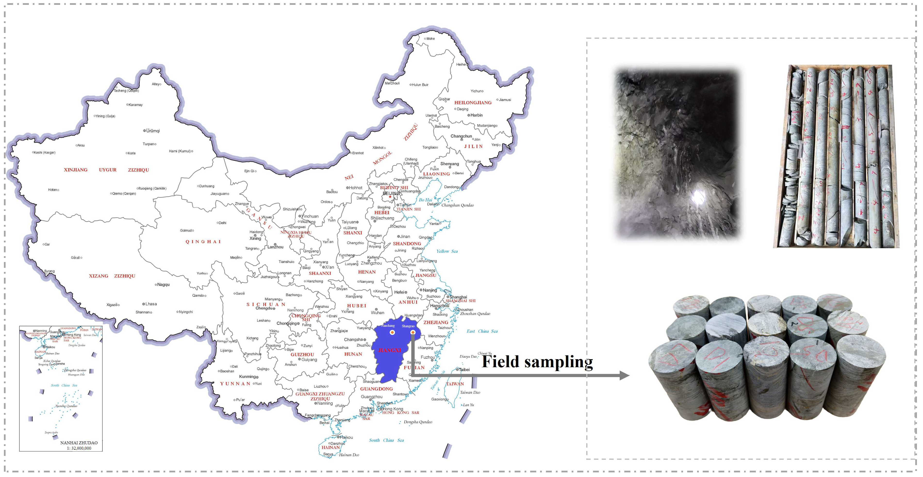
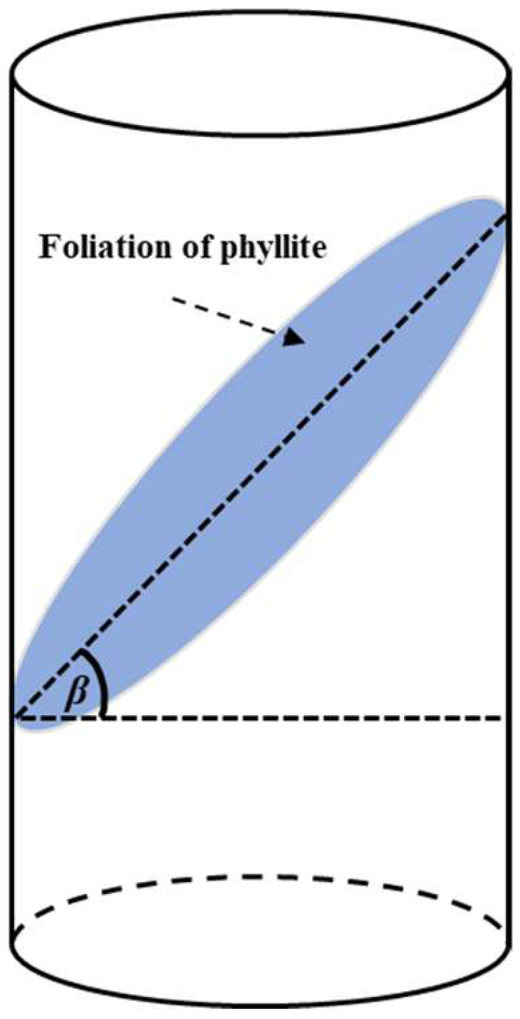
All specimens were collected from an underground mine in Shangrao, Jiangxi Province, China. To examine the effect of foliation angle, cores were drilled to obtain specimens spanning a range of foliation angles. Here, the foliation angle (β) is defined as the angle between the foliation plane and the horizontal plane (Figure 1). In this paper, the foliation angle is denoted by β. Specimens were prepared by cutting and end grinding in accordance with ISRM recommendations. End flatness and perpendicularity were controlled within the tolerances. The final specimens were cylinders 50 mm in diameter and 100 mm in height. Representative specimens are shown in Figure 2. Seven angles were tested: β = 0°, 15°, 30°, 45°, 60°, 75°, and 90°. For each foliation angle, specimens were prepared, and uniaxial compression tests were subsequently conducted on all samples to characterize their mechanical properties.
Uniaxial compression tests were conducted using an RMT uniaxial compression testing system, which provides stable loading control and high data acquisition accuracy, thereby satisfying the requirements for precise loading regulation and mechanical parameter monitoring in rock mechanics experiments. During testing, a displacement-controlled loading mode was adopted, with a constant loading rate of 0.002 mm/s. Loading continued until post-peak instability, indicated by a sharp load drop and loss of load-carrying capacity.

2.2. Mineral Composition and Structure of Phyllite Specimen

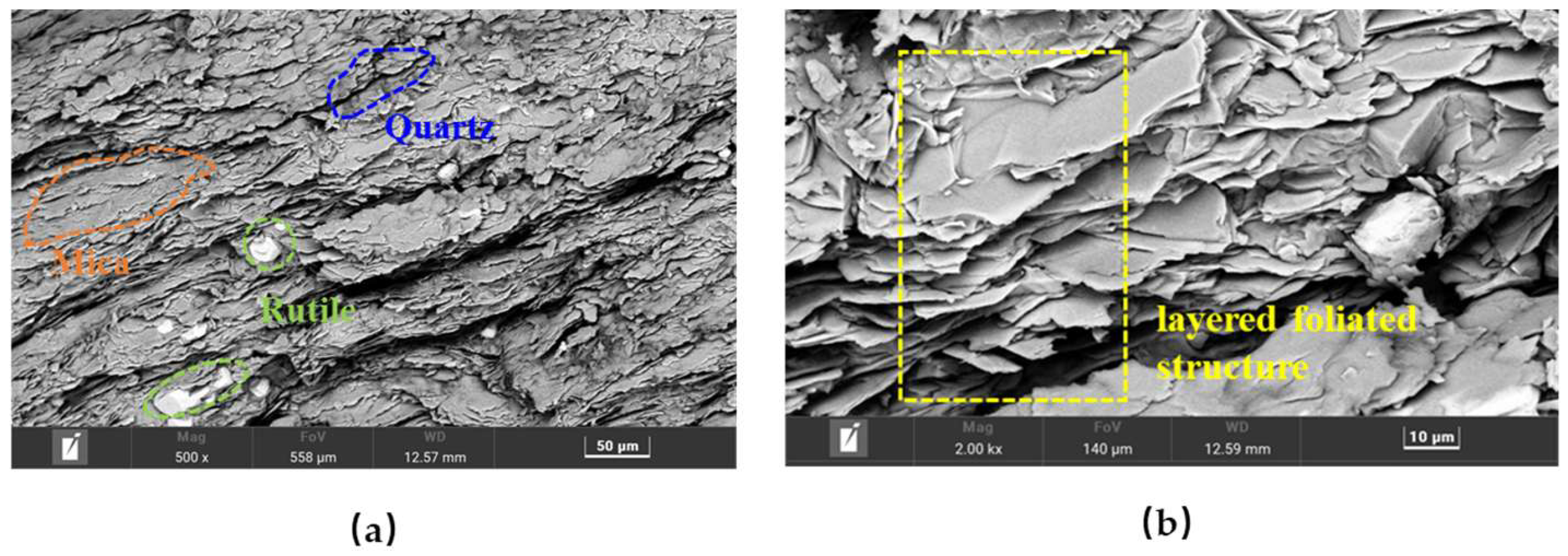
The structure of minerals has a significant impact on the initiation and propagation of cracks within rocks [52]. To further explore the mesoscopic structural characteristics of phyllite and reveal the microscopic essential mechanism of its anisotropic mechanical behavior, scanning electron microscopy (SEM) observations were conducted to characterize the micro-morphology of phyllite samples. As shown in Figure 3a,b, phyllite exhibits an integrated regular lamellar mesostructure with uniform sheet thickness. Its typical foliated morphology is determined by mineral assemblages and spatial distribution characteristics. Flaky mineral components are directionally and uniformly arranged along structural planes, forming a continuous thin-layered structure. The overall structure of phyllite is formed by the mutual superposition of multiple thin layers. Within the plane of a single thin layer, minerals are arranged uniformly and stably, and the rock exhibits isotropic macroscopic mechanical properties. In contrast, the interlayer contact surfaces formed by stacked thin layers possess weak mechanical properties and prominent structural differences, which ultimately lead to the obvious anisotropy of macroscopic mechanical parameters of phyllite.

3. Mechanical Behavior of Phyllite with Different Foliation Angles

3.1. Strength and Deformation Characteristics

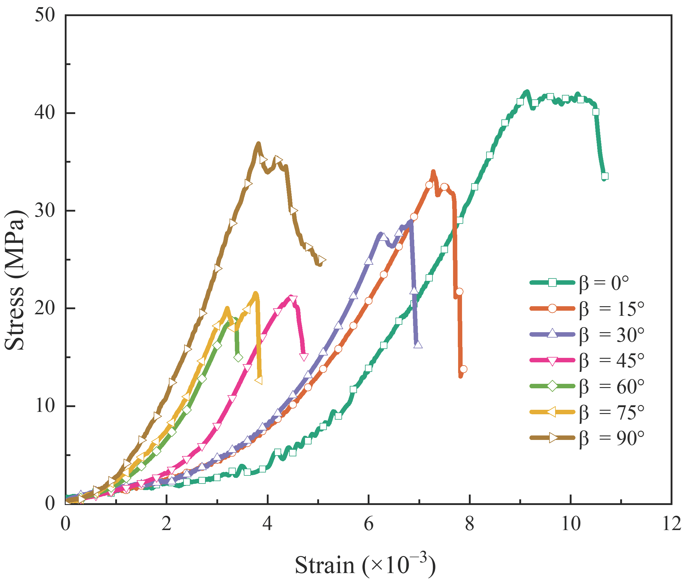
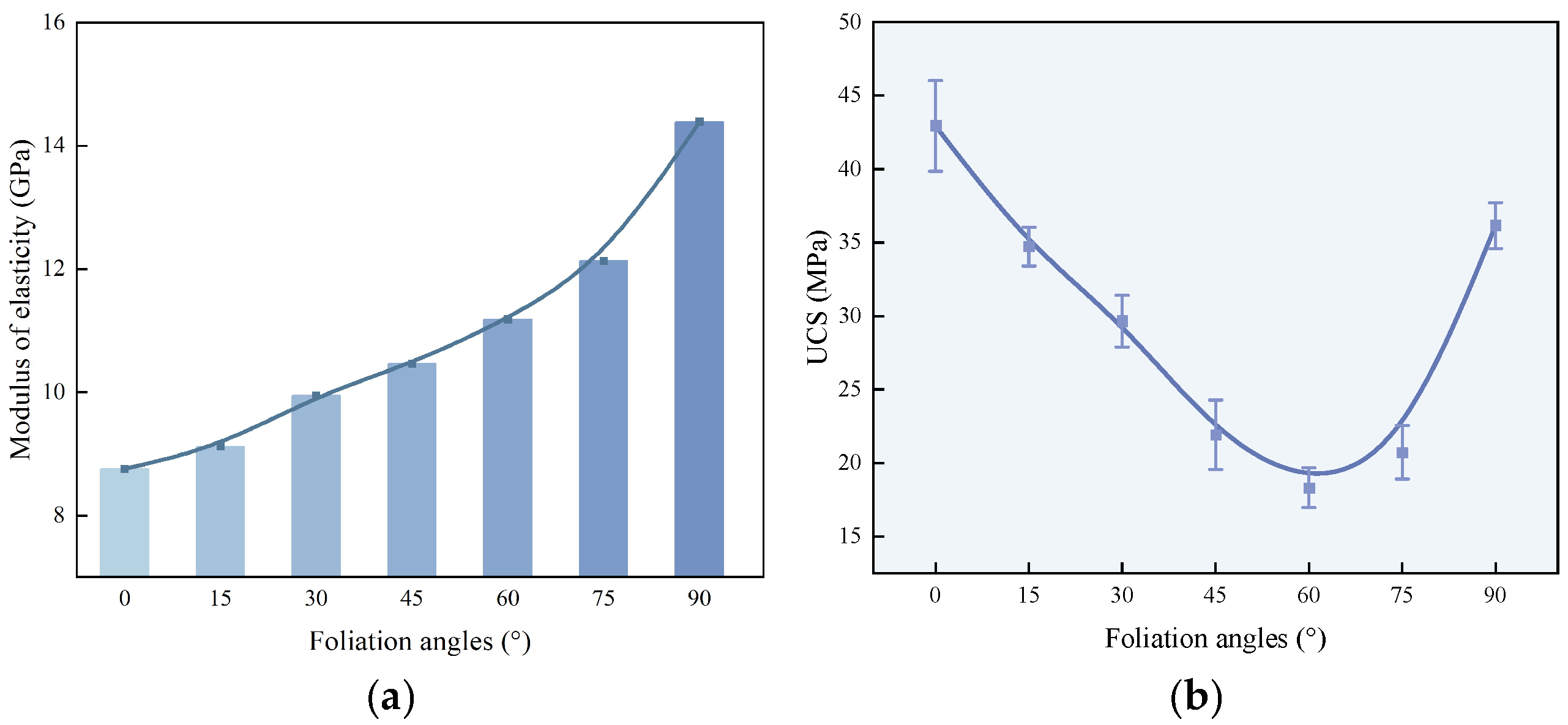
Figure 4 shows the uniaxial stress–strain curves of phyllite specimens with foliation angles β = 0°, 15°, 30°, 45°, 60°, 75°, and 90°. All curves exhibit three stages: compaction, linear elastic deformation, and post-peak failure. The stress level, strain accumulation, and post-peak response vary systematically with β, indicating strong anisotropy controlled by foliation angle. At low stresses, all specimens show a compaction phase that mainly reflects progressive closure of pre-existing pores and microcracks. The compaction slope depends on β: specimens with β = 0° and 15° show the least steep compaction segments, suggesting fewer defects favorably oriented for axial closure, whereas specimens with β = 75° and 90° exhibit a steeper compaction slope, consistent with discontinuities that are less effective in closing under axial loading. After compaction, the curves become approximately linear. Figure 5a shows that the elastic modulus depends strongly on β: the β = 0° specimen has the lowest modulus, and the modulus generally increases with β and peaks at β = 90°, consistent with a stiffer load transfer path dominated by the matrix rather than by slip along foliation planes.
For each foliation angle, a minimum of three specimens were tested to ensure experimental reproducibility. Figure 5b summarizes the peak stress versus β. The mean uniaxial compressive strength values for β = 0°, 15°, 30°, 45° 60°, 75°, and 90° are 42.93 MPa, 34.71 MPa, 29.65 MPa, 21.92 MPa, 18.31 MPa, 20.73 MPa, and 36.15 MPa, respectively. Peak stress varies non-monotonically with β, reaching a maximum at β = 0° and a minimum at β = 60°, followed by an increase toward β = 90°. Overall, peak stress follows a U-shaped trend with β, consistent with prior observations [8,9,10,11]. Post-peak behavior also depends on β. Specimens with β = 30–75° show an abrupt post-peak stress drop indicative of brittle instability. The specimen with β = 0° exhibits a near-plateau around peak stress, while specimens with β = 0°, 15°, and 90° maintain detectable residual capacity without abrupt collapse. These differences reflect distinct failure mechanisms: for β = 45–75° failure is dominated by shear sliding along foliation planes, while for β = 0°, 15°, and 90° matrix-dominated fracturing contributes to rougher failure surfaces that likely provide higher frictional resistance and moderate stress drops.

3.2. Macroscopic Failure Mode

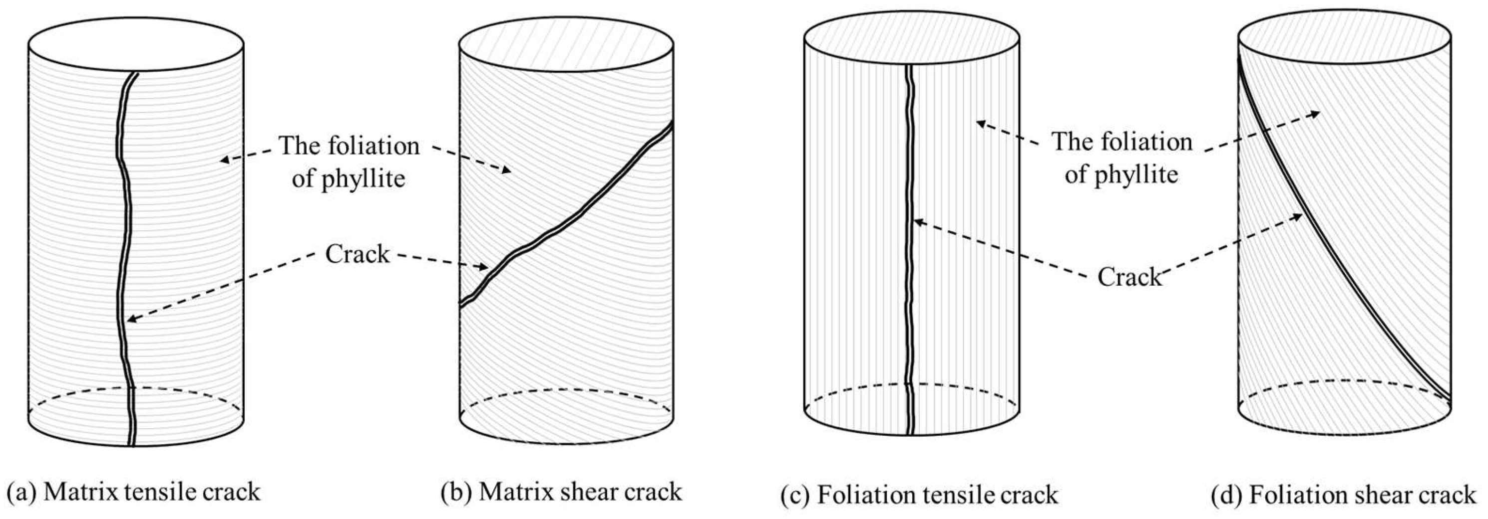
In rock deformation, cracks are commonly classified into tensile and shear cracks [53]. However, in phyllite, well-developed foliation planes—typically exhibiting lower cohesion and friction angle than the intact matrix—promote sliding or opening along the planes and hinder crack growth across foliation layers. Consequently, cracking in phyllite is controlled by both the applied stress state and the foliation architecture. As illustrated in Figure 6, considering both propagation path and failure mechanism, cracks in phyllite are grouped into four types: matrix tensile (M–T) crack, which propagate roughly parallel to the maximum principal stress and cut across foliation planes (Figure 6a); matrix shear (M–S) crack, which also traverse foliation layers but fail mainly by shear within the matrix (Figure 6b); foliation tensile (F–T) crack, which open along foliation planes (Figure 6c); and foliation shear (F–S) crack, which propagate along foliation planes and lead to shear sliding (Figure 6d).
Table 1 summarizes the characteristic failure modes of phyllite at different foliation angles under uniaxial compression. At β = 0°, the main outcome during destruction is the generation of M-S cracks. Failure is dominated by shear rupture within the matrix, with only minor local sliding along foliation planes; the resulting shear bands intersect foliation planes at an oblique angle, favoring crack linkage across foliation layers and culminating in throughgoing matrix shear fractures. At β = 15°, a limited number of M-T cracks initiate; nevertheless, matrix shear remains the governing mechanism, and the macroscopic fracture pattern is comparable to that for β = 0°. At β = 30°, the mechanical contrast between the foliation planes and the matrix becomes evident. M-S and F-S cracks develop concurrently, producing a composite mode in which deformation is accommodated partly by matrix shearing and partly by sliding along foliation planes. When β increases to 45°, the dominant failure mechanism shifts to shear sliding along foliation planes, while only sporadic M-S or M-T cracking is observed locally; under axial loading, the resolved shear stress concentrates preferentially on the foliation planes, and once it exceeds their frictional resistance and cohesion, sliding instability develops along the foliation direction.
At β = 60°, F-S cracking is dominant, and the specimens exhibit a typical foliation-controlled sliding mode, corresponding to the minimum uniaxial compressive strength. The general failure pattern at β = 75° is comparable to that at β = 60°; because the foliation planes provide limited shear resistance, F-S cracking propagates through the specimen and is often accompanied by minor spalling of rock fragments. At β = 90°, axial compression induces pronounced lateral extension due to the Poisson effect; when the transverse tensile stress exceeds the tensile strength of the foliation planes, tensile opening and/or slip develops along foliation, producing a layer-separation failure mode. Meanwhile, circumferential M-T cracks initiate in the matrix and ultimately drive global instability and complete specimen failure. In summary, foliation angle strongly influences crack development and macroscopic failure in phyllite, demonstrating that foliation architecture governs crack evolution pathways and contributes to the pronounced anisotropy observed under uniaxial compression.

3.3. Crack Evolution from Discrete Element Simulations

The discrete element method has been widely used to investigate rock deformation and failure mechanisms [54,55,56,57,58]. To interpret the meso-scale origin of foliation-controlled anisotropy, numerical simulations were conducted using PFC alongside the laboratory tests. A transversely isotropic DEM model was established with explicit foliation planes. In the DEM context, “microcracks” refer to bond-breakage or contact failure events at the particle scale; their accumulation and coalescence govern the meso-scale damage process and ultimately manifest as macroscopic fracture patterns and strength anisotropy.
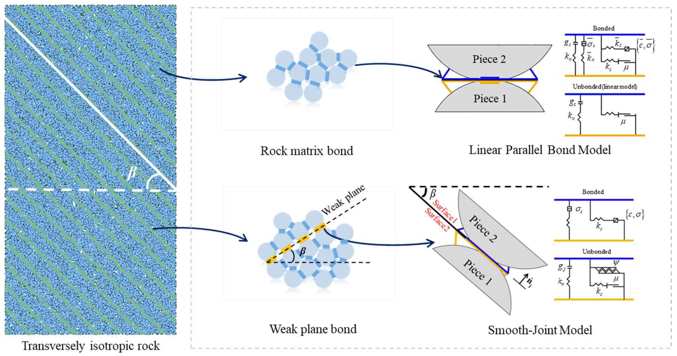
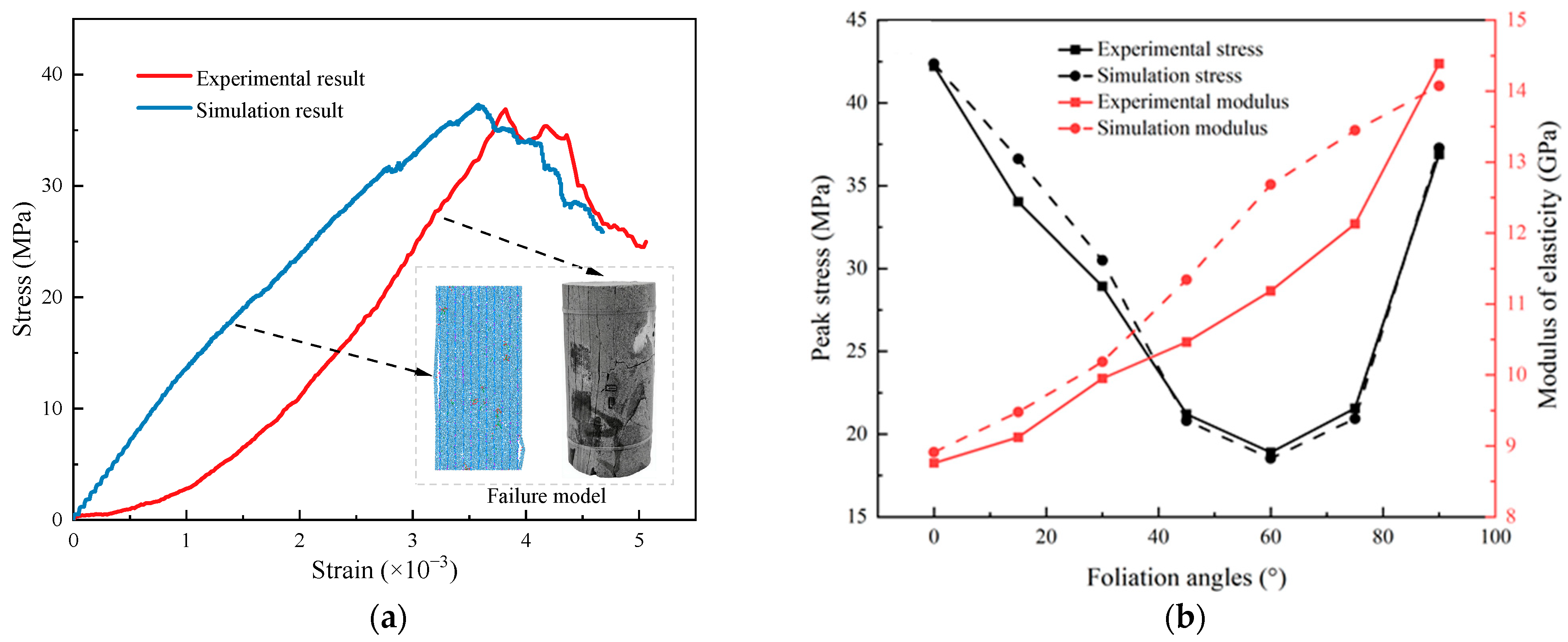
For the matrix, PFC provides two bonding schemes: the contact bond model (CBM) and the parallel bond model (PBM). The CBM does not transmit moments and retains contact stiffness after bond breakage, whereas the PBM transmits both forces and moments and removes bond stiffness once failure occurs; thus, macroscopic stiffness depends on both contact and bond contributions. Accordingly, the linear PBM was adopted for the phyllite matrix. To represent discontinuity-controlled deformation along foliation planes, the smooth-joint (SJ) model was introduced (Figure 7); it permits sliding along predefined foliation planes and allows for the tracking of joint opening/closure and contact forces. Initial mesoscopic parameter values were preliminarily determined from macroscopic laboratory test data, and a four-stage stepwise iterative calibration workflow was implemented to optimize the PBM and SJ parameters: first, basic particle parameters including density, stiffness ratio and friction coefficient were calibrated; second, tensile strength, cohesion and internal friction angle of matrix parallel bonds were adjusted to match the elastic modulus and peak strength of specimens with foliation planes perpendicular to the loading direction, third, normal stiffness, shear stiffness, tensile strength and cohesion of smooth joints were revised to reproduce the minimum strength value and foliation shear-slip failure characteristics of medium-dip specimens; fourth, global fine-tuning across all foliation angles was performed to simultaneously align the simulated stress–strain curves and macroscopic failure patterns of all seven groups of specimens. Parameter sensitivity analysis revealed that the peak strength of specimens with intermediate foliation angles (30–75°) is predominantly governed by the cohesion and internal friction angle of foliation joints, while the mechanical responses of low-and high-angle specimens are mainly controlled by the tensile strength of matrix parallel bonds. Quantitative reliability verification was further conducted: the relative errors of peak strength between simulation and laboratory tests for seven sets of specimens range from 0.38% to 7.61%, with a maximum error of only 7.61%, and the relative errors of elastic modulus fall within 1.76–13.40%, with the maximum value observed at the 60° foliation angle. The numerical simulations accurately reproduce the U-shaped distribution of uniaxial compressive strength and the monotonically increasing trend of elastic modulus with rising foliation angle. The calibrated matrix (PBM) and foliation plane (SJ) parameters are listed in Table 2. Figure 8a compares experimental and simulated stress–strain curves and failure modes for specimens with foliation planes parallel to the loading direction, and Figure 8b summarizes peak strength and elastic modulus across all foliation angles. The overall mechanical responses obtained from numerical modeling are in good agreement with experimental measurements, which fully verifies the rationality of the proposed calibration scheme and confirms that the established PFC model can accurately capture the anisotropic strength and deformation behaviors of phyllite.
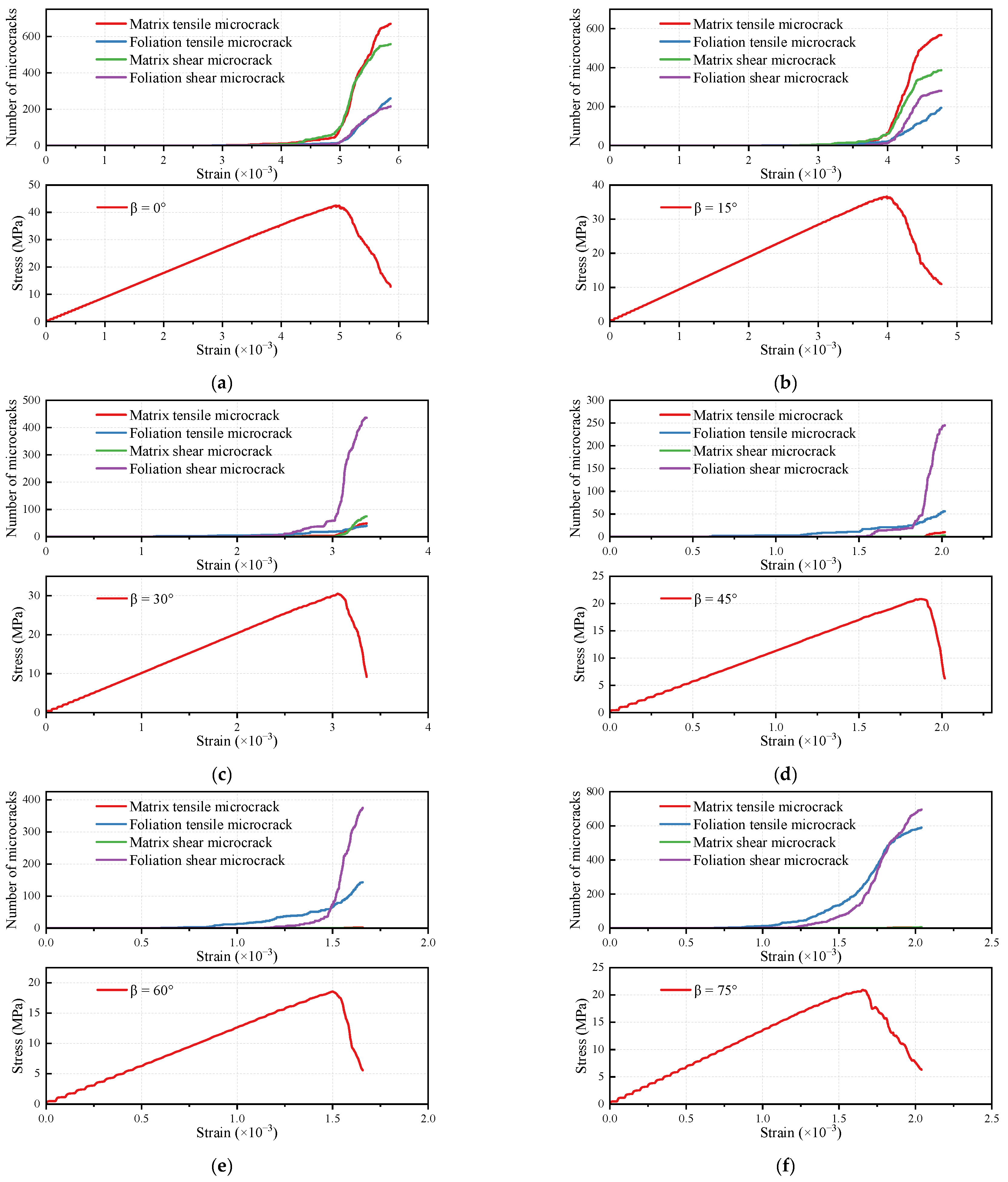
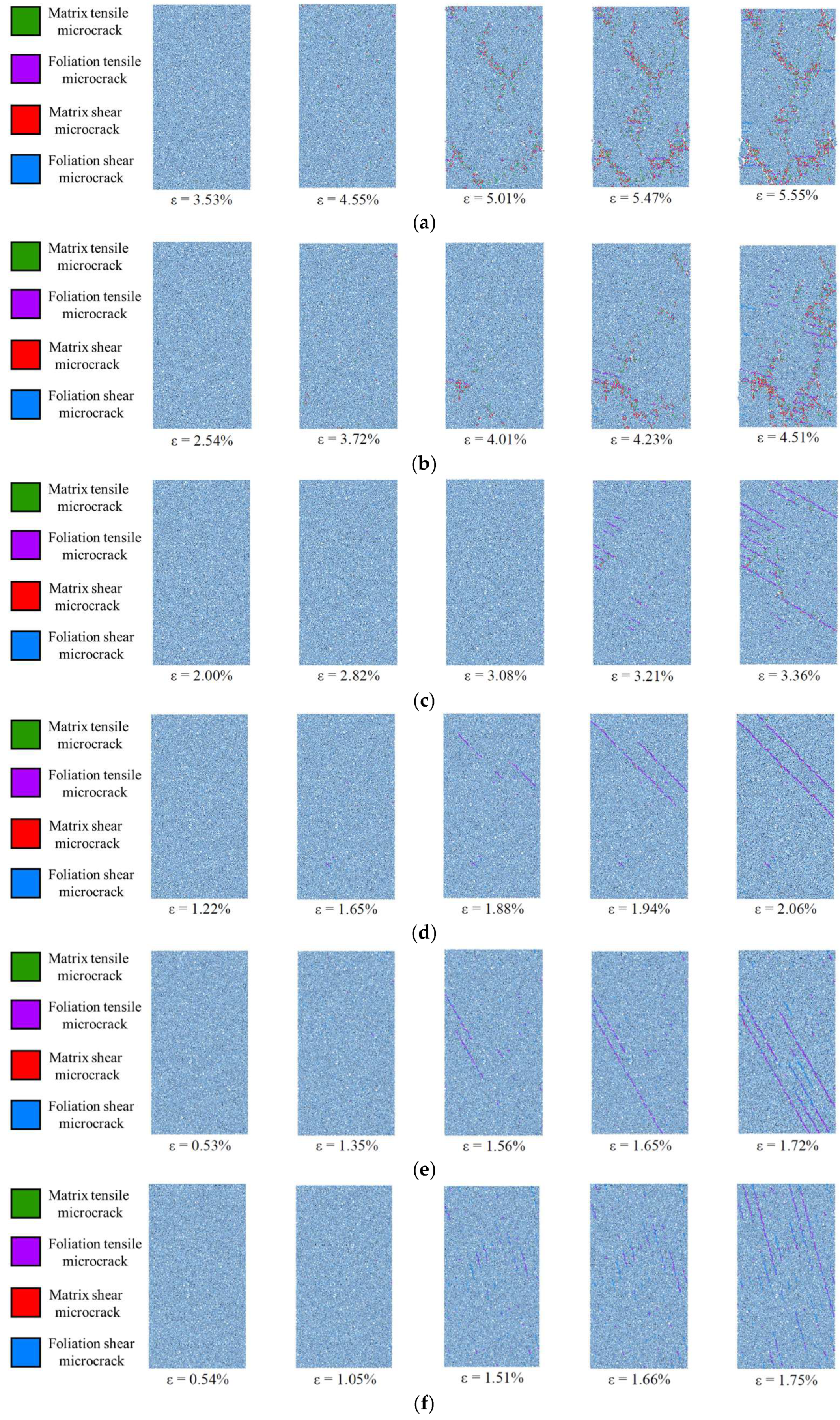
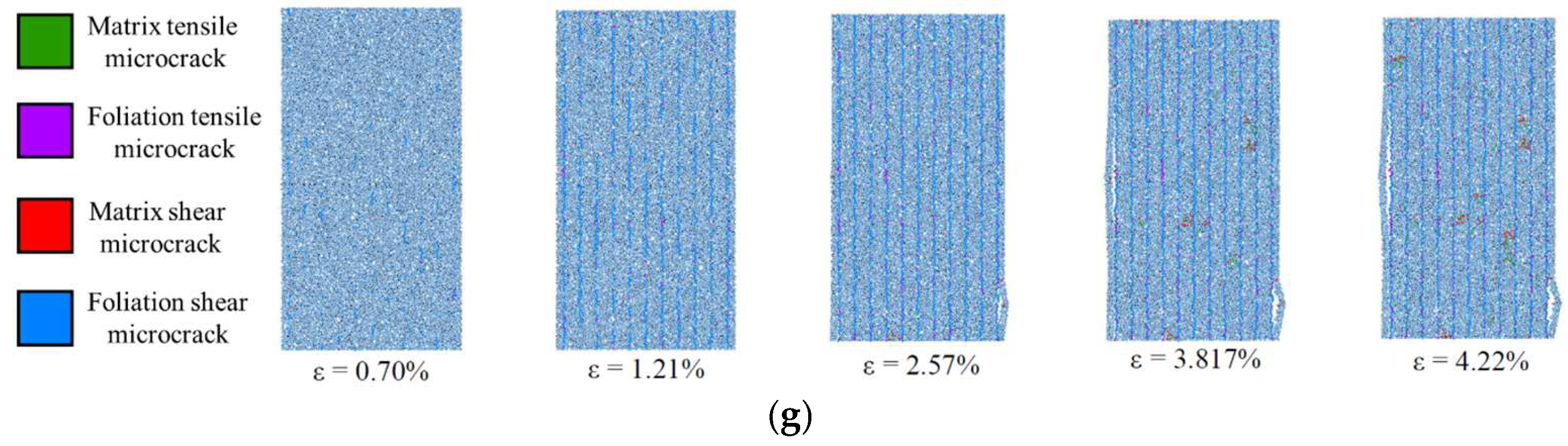
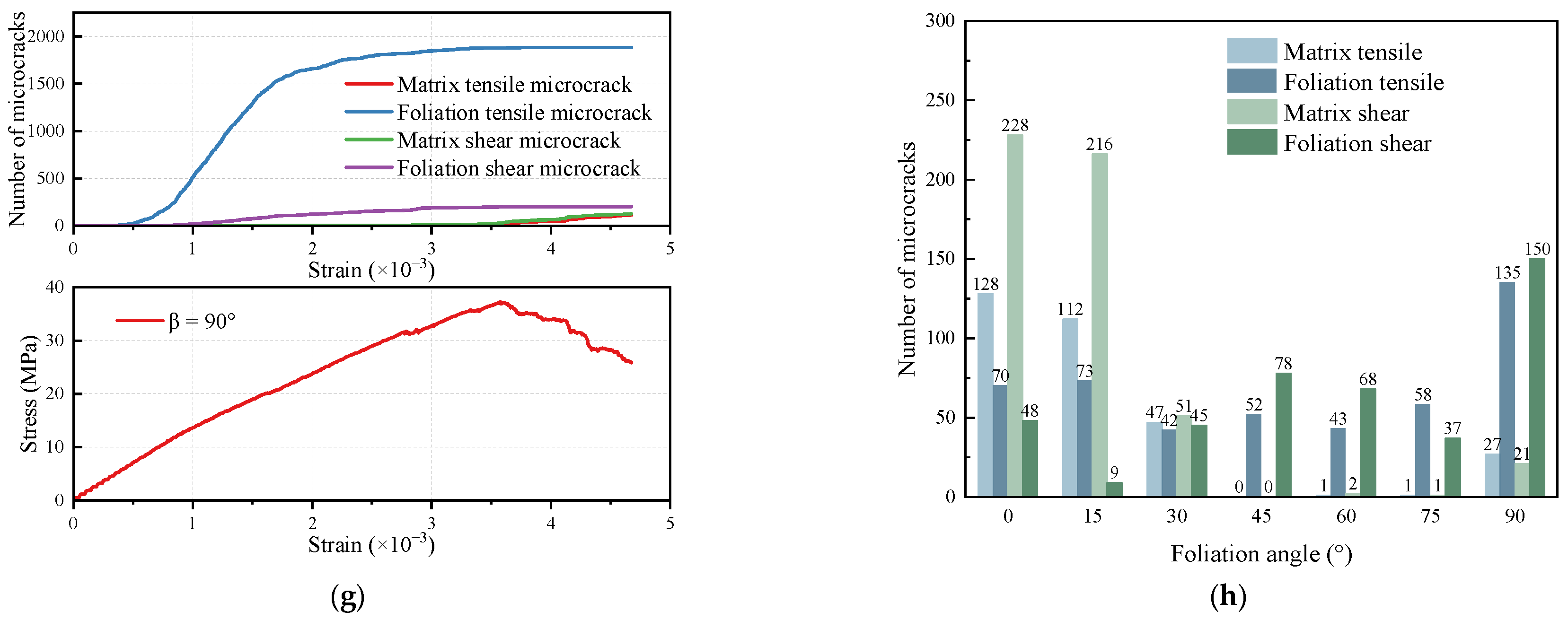
To quantitatively characterize damage evolution throughout uniaxial loading, a self-compiled FISH subroutine was developed to bind the bond-break mechanical event to a custom add_crack function for real-time microcrack capture. Based on two core criteria—contact model type and bond failure mode—all generated microcracks are systematically categorized into four mutually exclusive groups: matrix tensile, matrix shear, foliation tensile, and foliation shear microcracks. Specifically, contact failures occurring on linear parallel bond contacts correspond to matrix cracks, while breakages of smooth-joint contacts along foliation planes are defined as foliation cracks; bond failure mode 1 denotes tensile fracturing, and mode 2 represents shear fracturing. Independent global counting variables are initialized to continuously record the cumulative quantity of each crack type during the entire loading process, enabling quantitative analysis of mesoscopic crack evolution. Figure 9 and Figure 10 summarize spatial microcrack distributions, microcrack counts versus axial strain (with stress–strain curves), and the microcrack-type composition at peak stress for different β.
The microcrack evolution in phyllite with varying foliation angles under uniaxial compression demonstrates pronounced dip-dependent characteristics. Phyllite with low angles (0°, 15°) is primarily characterized by the early initiation and rapid propagation of matrix tensile–shear cracks. The onset of matrix cracks significantly precedes that of foliation cracks, with a relatively high crack growth rate observed before reaching peak stress. At peak stress, matrix cracks constitute over 80% of the total, ultimately leading to abrupt brittle failure under the combined action of matrix tension and shear. Under the 15° condition, the involvement of foliation cracks increases slightly, complicating the failure process. Phyllite with a medium dip angle (30°) deviates from the low-dip pattern of matrix-dominated initial damage, as matrix and foliation cracks initiate nearly simultaneously. The crack growth rate before peak stress decreases markedly, with a comparable number of both crack types at peak stress. Post-peak, these fissures accelerate simultaneously and move into a stage of synergistic matrix–foliation damage instability.
As the foliation angle progressively increases, the phyllite transitions towards a foliation-dominated damage evolution mode, with the characteristics of sudden failure exhibiting regular variations with dip angle. Under 45° and 60° conditions, foliation cracks entirely govern the damage process, accounting for a predominant proportion before peak stress, while matrix cracks nearly vanish at peak stress. Shear cracks serve as the primary damage vectors, with post-peak foliation cracks expanding explosively, resulting in pronounced instability and abrupt failure. In the 75° scenario, tensile cracks in the foliation initiate earlier than shear cracks, and post peak, the synergistic action of tensile and shear forces in the foliation leads to severe damage, causing noticeable slippage of the specimen along the foliation plane. The 90° condition exhibits unique two-stage failure characteristics, with slow accumulation of foliation cracks before peak stress, decelerated foliation crack propagation post-peak, and sudden initiation and coalescence of matrix cracks forming macroscopic failure surfaces, ultimately leading to specimen failure due to matrix instability. In summary, the meso-fracture mechanism of phyllite under uniaxial compression undergoes an orderly transition with increasing foliation angle, evolving from low-dip matrix tensile–shear dominance and medium-dip coordinated damage to medium-high-dip foliation shear dominance and high-dip foliation tensile–shear coordination, culminating in a two-stage failure pattern characterized by high-dip foliation initiation followed by matrix closure.

4. Discussion on Strength Anisotropy and Fracture Mechanisms

4.1. The Controlling Effect of Weak Planes

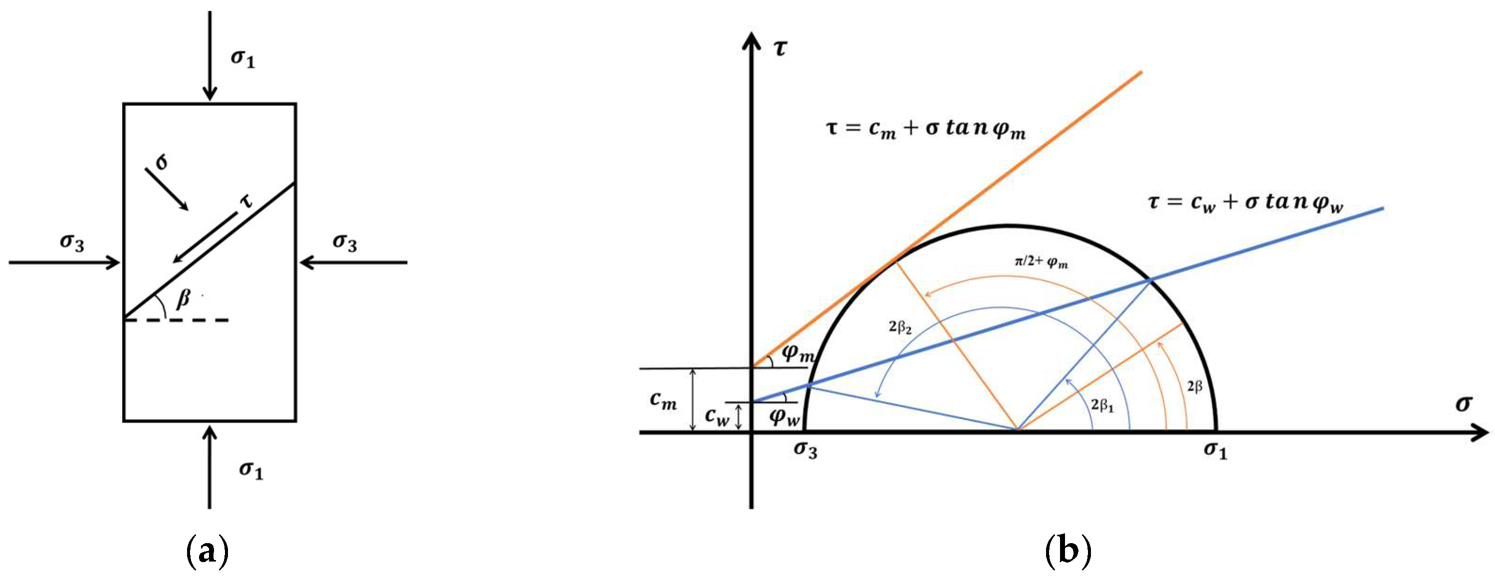
The Jaeger plane-of-weakness (JPW) model [50] provides a classical framework for describing the strength anisotropy of layered rocks and is formulated on the Mohr–Coulomb criterion. In Figure 11, plane AB represents the weak plane, and its inclination is denoted by β. From Mohr’s circle, the normal stress (σ) and shear stress (τ) on plane AB are given by Equation (1).
σ n = 1 2 σ 1 + σ 3 + 1 2 σ 1 σ 3 c o s   2 β τ = 1 2 σ 1 σ 3 s i n   2 β
Shear failure along the weak plane is assumed to follow the Coulomb criterion (Equation (2)):
τ = c w + σ tan   φ w
where  c w  and  φ w  denote the cohesion and internal friction angle of the weak plane, respectively.
Substituting Equation (1) into Equation (2) and rearranging gives the limit equilibrium condition for foliation plane shear failure (Equation (3)), which can be further expressed by Equation (4).
σ 1 σ 3 2 sin   2 β tan   φ w cos   2 β = c w + σ 1 + σ 3 2 t a n   φ w
σ 1 = σ 3 + 2 c w + σ 3 tan   φ w 1 tan   φ w cot   β sin   2 β
By taking the extreme value of Equation (4) with respect to β, the critical angle corresponding to the most dangerous shear failure of weak planes can be obtained as follows:
β 0 = π 4 + φ w 2
At this weak-plane angle  β 0 σ 1  reaches the minimum value, which is consistent with the experimental law that the rock strength is the lowest at a angle of approximately 60°.
When the weak-plane angle is outside the weak-plane failure range, the rock undergoes matrix shear failure, and its strength is controlled by matrix parameters:
σ 1 = σ 3 + 2 c m + σ 3 tan   φ m 1 tan   φ m cot   β 0 sin   2 β 0
where  c m  and  φ m  denote the cohesion and friction angle of the matrix, respectively.
The uniaxial compressive strength of intact rock matrix ( σ 3 = 0 , with β taken as the matrix failure angle) is expressed as follows:
σ 1 = 2 c m cos   φ m 1 sin   φ m
As shown in Figure 11b, the failure mode of phyllite can be determined based on the relationship between the Mohr strength envelope and stress Mohr circle. Two critical angles  β 1  and  β 2  exist for this failure discrimination. Phyllite fails by shear slipping along weak planes when  β 1 < β < β 2 , while matrix shear failure occurs when  β < β 1  or  β > β 2 . The expressions of  β 1  and  β 2  are given by Li et al. [22] and Deng et al. [12].
β 1 = φ w 2 + 1 2 arcsin σ 1 + 2 c w cot   φ w sin   φ w σ 1 β 2 = π 2 + φ w 2 1 2 arcsin σ 1 + 2 c w cot   φ w sin   φ w σ 1
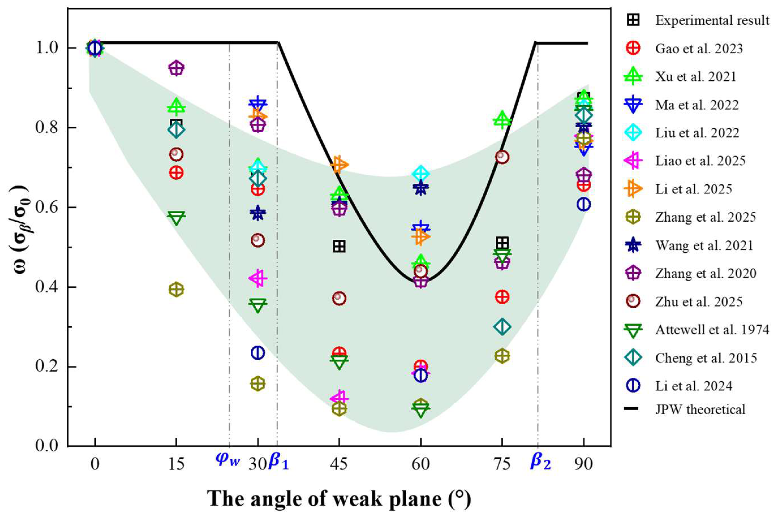
Numerous studies have adopted the JPW criterion to elaborate the anisotropic characteristics of strength and failure modes for layered rocks such as phyllite, shale and schist [27]. Nevertheless, the JPW model exhibits evident limitations in practical application. Considerable discrepancies exist between the strength curves of phyllite with various foliation angles and the prediction curves derived from the JPW theory [22]. In this study, the uniaxial compressive strength of rocks with different weak-plane angles is normalized and defined as follows:
ω = σ β σ 0
where  σ β  is the uniaxial compressive strength of rocks with a weak-plane angle of β, and  σ 0  represents the uniaxial compressive strength of rocks at a weak-plane angle of 0°.
As illustrated in Figure 12, the green shaded area represents the main coverage range and variation trend of the data points. Statistical analysis on the strength evolution laws of transversely isotropic rocks including phyllite, shale and schist indicates that the calculated values of the JPW theory deviate significantly from the experimental measured data. The theoretical study of the JPW criterion given above states that when  β < β 1  or  β > β 2 σ β  =  σ 0 . However, within the above angle ranges, the normalized strength ω obtained from statistical results is consistently less than 1 and gradually decreases with the increase in angle. Moreover, the measured strength of rock specimens at a weak-plane angle of 90° is also lower than that of specimens at 0°, which is inconsistent with the theoretical predictions of the JPW criterion.
The fundamental assumption of the JPW theory is that rock contains only a single set of continuous and planar weak planes, with failure modes limited to weak plane sliding failure or intact matrix failure. Combined with macroscopic failure observations and particle flow numerical simulation results of phyllite, it is confirmed that transversely isotropic rocks under loading do not undergo merely single matrix cracking or weak plane cracking; instead, coupled propagation of matrix cracks and foliation cracks dominates the failure process. For transversely isotropic rocks, crack development of rock matrix and foliation planes presents a mutual interaction effect. Matrix crack propagation promotes the initiation and expansion of foliation cracks, and foliation cracking in turn exacerbates the damage of rock matrix.

4.2. Intrinsic Mechanisms of Foliation Crack Initiation Induced by Matrix Cracking

Failure in phyllite primarily arises from the coupled evolution of matrix cracking and foliation plane cracking. The interaction between these two crack systems can be interpreted using fracture mechanics concepts, and its intensity varies with the foliation angle β thereby influencing both strength anisotropy and the associated failure modes.
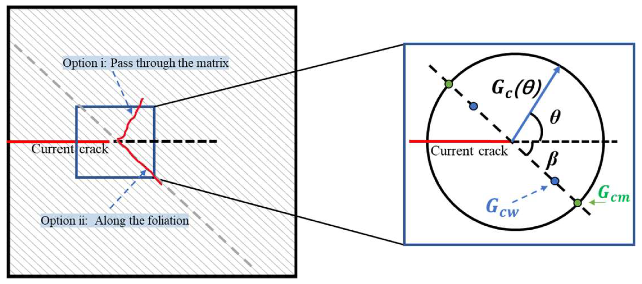
As illustrated in Figure 13, a matrix crack approaching a foliation weak plane can be idealized as facing two competing propagation paths: (i) penetration across the foliation plane and continued growth within the matrix, or (ii) deflection at the interface followed by propagation along the foliation plane. Under far-field mixed-mode (I/II) loading, the stress intensity factors at the crack tip are denoted as  K I  and  K I I . In linear elastic fracture mechanics [62], the energy release rate for crack growth along an arbitrary direction θ can be expressed in terms of the stress intensity factors. Let  G c , w  and  G c , m  denote the mode-I fracture toughness (critical energy release rate) of the foliation plane and the matrix, respectively. For the tested phyllite,  G c , w < G c , m  due to the weak interlayer bonding of aligned mica minerals, creating a preferential low-energy path for crack propagation. Penetration across the foliation plane and deflection along the foliation plane (θ = β) are thus characterized by energy release rates  G p , and  G d , respectively.
According to the maximum energy release rate criterion, deflection occurs when the driving force-to-resistance ratio for growth along the foliation plane exceeds that for penetration through the matrix, i.e., Equation (10).
G d G c , w > G p G c , m
Substituting the energy release rate expressions into Equation (10) yields Equation (11).
G d K I , K I I , β G p K I , K I I > G c , w G c , m
This criterion shows that the competition between penetration and deflection is controlled by the loading mode  ( K I , K I I ) , and the toughness contrast  G c , w / G c , m  between the matrix and the foliation plane.
For a given material, with fixed values of  G c , w / G c , m  and a prescribed loading mode characterized by a constant ratio  K I / K I I , the ratio  G d / G p  is a function of the angle β. He and Hutchinson [63] theoretically demonstrated that a critical angle  β c r  exists for the deflection–penetration transition. When  β < | β c r | , Equation (11) is satisfied and the crack preferentially deflects along the foliation plane; conversely, when  β > | β c r | , Equation (11) is not satisfied and penetration through the foliation plane becomes favorable. Over commonly encountered parameter ranges,  G d / G p  increases as  β  decreases. This trend implies that as the foliation plane becomes more aligned with the original matrix crack growth direction, a higher relative foliation toughness  G c , w / G c , m  is required to suppress deflection, making deflection increasingly favorable at small β.
This deflection mechanism is the mesoscopic origin of the coupled evolution of matrix and foliation cracks. Even when macroscopic failure remains matrix-dominated at low β, the early deflection of matrix cracks along foliation planes initiates weak-plane damage, which in turn intensifies stress concentration in the adjacent matrix and accelerates matrix crack propagation. Such interaction invalidates the classical Jaeger theory’s assumption of independent matrix and foliation failure, and provides a mechanistic basis for the observed gradual decrease in normalized strength when  β < β 1 . For transversely isotropic rocks (e.g., phyllite, schist), failure under loading therefore commonly reflects coupled evolution of matrix cracking and weak-plane-parallel cracking, rather than a purely matrix-controlled or purely weak-plane-controlled process.

4.3. Intrinsic Mechanisms of Foliation Cracks Inducing Matrix Crack Propagation

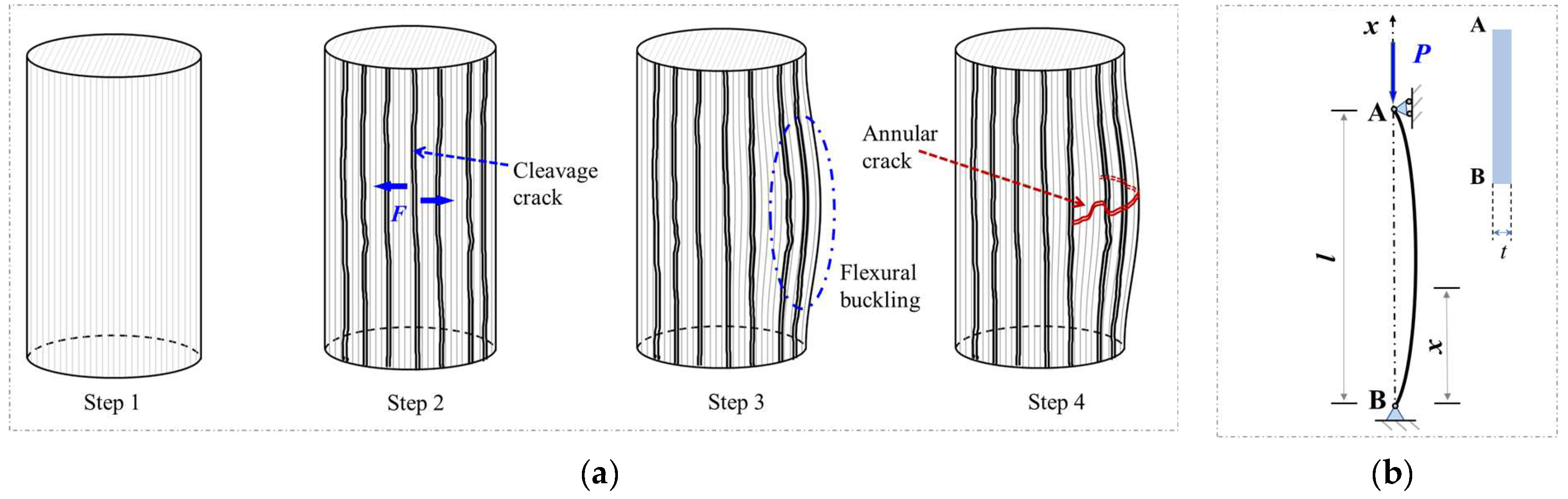
At large foliation angles, tensile opening and/or shear sliding along foliation planes can trigger interface delamination. As shown in Figure 14a, for β = 90°, Poisson-induced transverse tensile strain promotes tensile opening along foliation planes, splitting the intact specimen into thin slabs. The resulting slabs then buckle under axial compression, and circumferential matrix cracking develops during global instability. Subsequently, these thin slabs undergo buckling instability under axial loading [64], resulting in global instability accompanied by the formation of circumferential cracks. At the early stage of failure, each thin slab can be idealized as an elastic column subjected to axial compression, and the corresponding mechanical model is shown in Figure 14b.
Consider a straight elastic column of length l subjected to an axial compressive load P. Let w(x) denote the lateral deflection. Under the small-deflection assumption, the governing equation is as follows:
E m I d 4 w d x 4 + P d 2 w d x 2 = 0
Here,  E m  is the Young’s modulus of the matrix, l is the column length (loading direction), and t is the slab thickness (normal to foliation). A unit width is assumed, giving A = t and I as the second moment of area.
Accordingly, with unit width, A = t, the corresponding axial critical stress can be expressed as follows:
σ c r = P c r A = π 2 E m 12 t μ l 2
where μ represents the effective length factor depending on the end boundary constraints.
Equation (13) indicates that once foliation separation occurs, the load-carrying capacity of the rock is primarily dictated by the geometric thickness-to-length ratio rather than the intrinsic compressive strength of the intact matrix. Consequently, the formation of multi-slab column structures causes premature structural instability at stress levels significantly lower than the matrix strength, providing a clear mechanical interpretation for the strength reduction at β = 90° relative to β = 0° that cannot be captured by the classical JPW theory.
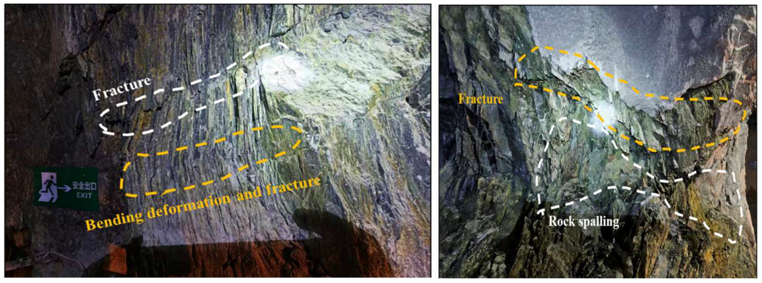
To bridge laboratory observations with practical geo-engineering applications, the connection and specificity of buckling instability across meso-and macro-scales require further consideration. Fundamentally, buckling failure across both scales shares an identical evolutionary path, starting with progressive interlayer tensile delamination, followed by flexural bending of the resulting slender rock slabs, and concluding in ultimate structural collapse. In both cases, weak-plane separation alters the internal load-bearing framework, converting a solid continuum into a discrete multi-slab system and substantially lowering its effective bearing capacity. Nevertheless, pronounced differences exist in boundary constraints and stress environments across these scales. At the meso-scale of laboratory specimens, buckling occurs under displacement-controlled uniaxial compression with well-constrained planar ends, where foliation opening is driven purely by lateral expansion from the Poisson effect and manifests as relatively symmetric lateral deflections. In contrast, at the macro-scale of underground cavern and tunnel sidewalls shown in Figure 15, buckling is governed by poly-axial stress fields characterized by excavation-induced stress relief. High tangential stress concentration combined with radial unloading induces preferential slab bending toward the unconfined excavation boundary. Moreover, macro-scale rock slabs typically exhibit larger slenderness ratios, irregular layer thicknesses, and pre-existing transverse discontinuities, causing failure to manifest as localized slab bending, rib spalling, or toppling with plastic hinges rather than ideal elastic buckling.
These scale-dependent characteristics yield valuable insights for engineering design. Conventional stability evaluations relying on continuum shear failure criteria such as the Mohr–Coulomb and JPW models substantially overestimate the stand-up time and bearing capacity of steeply dipping layered surrounding rocks by neglecting buckling-induced instability. In engineering practice, support schemes for such rock masses should prioritize applying pretensioned rock bolts or anchor cables perpendicular to foliation planes to suppress initial delamination, while deploying reinforced shotcrete linings to shorten the effective buckling length of exposed rock plates, thereby mitigating buckling and rib spalling hazards.

5. Conclusions

To elucidate the influence of foliation angle (β) on mechanical behavior anisotropy and fracture mechanisms, uniaxial compression tests were conducted on specimens with seven different foliation angles and supplemented by particle flow numerical simulations. The main conclusions are as follows:
(1) The foliation angle in phyllite has a significant effect on the stress–strain curve. The peak stress displays a typical U-shaped dependence on foliation angle, reaching a minimum near β = 60° and relatively higher values at β = 0° and 90°. In contrast, elastic modulus generally increases with increasing β.
(2) The failure modes of phyllite vary significantly with the foliation angle. When β = 0–15°, failure is dominated by matrix shear rupture. At β = 30°, failure is jointly controlled by matrix cracking and foliation cracking. At β = 45–75°, shear sliding along foliation planes becomes the dominant failure mode. At β = 90°, tensile opening of foliation planes induces slab separation, followed by buckling instability controlled by matrix deformation.
(3) A stage-dependent transition in dominant microcrack processes is indicated by the simulations. At small β, damage is controlled by matrix tensile and shear microcracks. At intermediate β, foliation shear microcracks govern the response. At large β, early coalescence of foliation tensile microcracks precedes the rapid growth of matrix microcracks, which ultimately governs global instability.
(4) The traditional JPW theory can only qualitatively describe the shear failure law of phyllite along foliation weak planes within the moderate foliation angle range of  β 1 < β < β 2 . However, neglecting the synergistic evolution of matrix–foliation cracks, this theory produces obvious prediction deviations at low angles ( β < β 1 ) and high angles ( β > β 2 ). Combining the fracture mechanics energy release rate criterion and the compression bar stability theory, this study clarifies the mutual induction mechanism of the two types of cracks. At low angles, the propagation direction of cracks and foliation angle jointly control the penetration and deflection behaviors of matrix cracks near weak planes. Consequently, rock failure remains dominated by matrix damage, while the overall strength decreases gradually. At high angles, tensile fractures along foliation divide the rock into thin layered slices. Under axial loading, these thin slices suffer buckling instability, which serves as the primary reason why the rock strength at high angles is lower than that of specimens at 0°.

Author Contributions

Conceptualization, Y.Y. and K.Z.; methodology, Y.Y. and Y.W.; software, K.Z. and Y.W.; validation, Y.Y.; formal analysis, P.Z. and C.L.; investigation, L.X. and C.L.; resources, Y.W.; data curation, Y.Y.; writing—original draft preparation, Y.Y.; writing—review and editing, C.L., K.Z. and P.Z.; visualization, C.L.; supervision, Y.W.; project administration, K.Z. and P.Z.; funding acquisition, K.Z. and C.L. All authors have read and agreed to the published version of the manuscript.

Funding

This research was funded by the State Key Laboratory Special Programs of China Minmetals Corporation (2024GZKJ04), and the Guangxi Key Research and Development Program (2022AB31022).

Institutional Review Board Statement

Not applicable.

Informed Consent Statement

Not applicable.

Data Availability Statement

The original contributions presented in the study are included in the article, further inquiries can be directed to the corresponding authors.

Acknowledgments

We sincerely thank the reviewers for their valuable comments and insightful suggestions, which significantly improved this work.

Conflicts of Interest

Author Yunmin Wang was employed by the company Sinosteel Maanshan Institute of Mining Research Co., Ltd., Author Chang Liu was employed by the company Changsha Institute of Mining Research Co., Ltd. The remaining authors declare that the research was conducted in the absence of any commercial or financial relationships that could be construed as a potential conflict of interest. The authors declare that this study received funding from State Key Laboratory Special Programs of China Minmetals Corporation. The funder had the following involvement with the study: funding acquisition, project administration, and manuscript review.

Abbreviations

The following abbreviations are used in this manuscript:
UCSUniaxial Compressive Strength
PFCParticle Flow Code
PBMParallel Bond Model
SJSmooth-Joint
SEMScanning Electron Microscopy
XRDX-ray Diffraction

References

  1. Özbek, A.; Gül, M.; Karacan, E.; Alca, Ö. Anisotropy effect on strengths of metamorphic rocks. J. Rock Mech. Geotech. Eng. 2018, 10, 164–175. [Google Scholar] [CrossRef] [Scilit]
  2. Si, X.; Luo, Y.; Luo, S. Influence of lithology and bedding orientation on failure behavior of “D” shaped tunnel. Theor. Appl. Fract. Mech. 2024, 129, 104219. [Google Scholar] [CrossRef] [Scilit]
  3. Lana, M.S. Numerical modeling of failure mechanisms in phyllite mine slopes in Brazil. Int. J. Min. Sci. Technol. 2014, 24, 777–782. [Google Scholar] [CrossRef] [Scilit]
  4. Li, T.; Peng, F.; Chen, C.; Ma, C.; Li, Y.; Wang, Y.; Li, Y. Investigating the Creep Damage and Permeability Evolution Mechanism of Phyllite Considering Non-Darcy’s Flow. Rock Mech. Rock Eng. 2024, 57, 8483–8498. [Google Scholar] [CrossRef] [Scilit]
  5. Wang, S.; He, C.; Xu, G.; Bai, R.; Shu, Y.; Wang, J.; Yue, J.; Zhang, W. Investigating failure modes and Micro-Crack classification in Mao phyllite under notched Semi-Circular bend testing. Theor. Appl. Fract. Mech. 2024, 130, 104319. [Google Scholar] [CrossRef] [Scilit]
  6. Cao, Y.; Deng, L.; Fan, W.; Tang, D.; Chen, J.; Zheng, B. Failure characteristics and mechanism of a layered phyllite landslide triggered by foot excavation in the Qinba Mountains of China. Bull. Eng. Geol. Environ. 2024, 83, 366. [Google Scholar] [CrossRef] [Scilit]
  7. Abbasi, V.; Ahmadi, M.; Mohtarami, E.; Karimi, J.; Saberi, F. Experimental and numerical failure mechanism evaluation of anisotropic rocks using extended finite element method. Theor. Appl. Fract. Mech. 2024, 131, 104411. [Google Scholar] [CrossRef] [Scilit]
  8. Xu, J.; Fei, D.; Yu, Y.; Cui, Y.; Yan, C.; Bao, H.; Lan, H. Research on crack evolution law and macroscopic failure mode of joint Phyllite under uniaxial compression. Sci. Rep. 2021, 11, 4196. [Google Scholar] [CrossRef] [Scilit] [PubMed]
  9. Liu, G.; Peng, Y.; Zuo, Q.; Su, Y.; Wu, L. Dynamic Mechanics and Energy Dissipation of Saturated Layered Phyllite. Minerals 2022, 12, 1246. [Google Scholar] [CrossRef] [Scilit]
  10. Ma, L.; Chen, J.; Zhao, Y.; Zhang, C.; Liu, R.; Ren, S. Water Content and Bedding Angle Effects on the Mechanical Properties and Micro-/Macro-Failure Mechanism of Phyllite. Arab. J. Sci. Eng. 2022, 47, 13151–13169. [Google Scholar] [CrossRef] [Scilit]
  11. Zhang, J.; Zhang, X.; Huang, Z.; Huang, J. A brittle-ductile index for transversely isotropic rock based on energy evolution of the characteristic stress and its application. Bull. Eng. Geol. Environ. 2023, 82, 35. [Google Scholar] [CrossRef] [Scilit]
  12. Deng, T.; Liu, B.; Shi, X.; Chu, Z.; Zhang, X.; Yu, M. Anisotropic Mechanical Properties of Sericite Phyllite Under Dry and Saturated Conditions. Rock Mech. Rock Eng. 2025, 58, 6407–6434. [Google Scholar] [CrossRef] [Scilit]
  13. Xu, L.; Gong, F.; Dai, J.; He, Z. Effects of bedding angles on rockburst proneness of layered anisotropic phyllites. J. Rock Mech. Geotech. Eng. 2025, 17, 4288–4313. [Google Scholar] [CrossRef] [Scilit]
  14. Fereidooni, D.; Khanlari, G.R.; Heidari, M.; Sepahigero, A.A.; Kolahi-Azar, A.P. Assessment of Inherent Anisotropy and Confining Pressure Influences on Mechanical Behavior of Anisotropic Foliated Rocks Under Triaxial Compression. Rock Mech. Rock Eng. 2015, 49, 2155–2163. [Google Scholar] [CrossRef] [Scilit]
  15. Liao, A.; Zhang, Y.; Meng, K.; Zheng, X.; Zou, M.; Xia, M.; Fang, J. Mechanical properties and damage characteristics of phyllite subjected to high-temperature treatment. Results Eng. 2025, 28, 107252. [Google Scholar] [CrossRef] [Scilit]
  16. Liu, Q.; Zhang, C.; Hou, J.; Li, L. Experimental and numerical research on the anisotropic compressive mechanical behavior of layered rock. Sci. Rep. 2025, 15, 45106. [Google Scholar] [CrossRef] [Scilit] [PubMed]
  17. Wu, Y.; Yang, D. Study on mechanical characteristics of phyllite by conventional triaxial compression under multi-factors coupling action. Sci. Rep. 2024, 14, 30322. [Google Scholar] [CrossRef] [Scilit] [PubMed]
  18. Xu, J.; Zeng, X.; Sun, H.; Qiao, W.; Wu, X.; Zhao, D.; Qi, Y. Investigation into the degradation patterns of the physical and mechanical characteristics of phyllite within a hydrothermal environment. Bull. Eng. Geol. Environ. 2024, 83, 122. [Google Scholar] [CrossRef] [Scilit]
  19. Singh, P.K.; Pradhan, S.P.; Vishal, V. Analysis of tensile failure mechanism in intact, foliated, and cracked rocks using distinct element method: Influence of anisotropy. Eng. Fail. Anal. 2024, 166, 108859. [Google Scholar] [CrossRef] [Scilit]
  20. Guo, X.; Tan, Z.; Wang, X.; Li, A.; Ma, Z.; Wu, Y. Effect of Bedding Angle and Mineral Composition on Mechanical Properties and Fracture Behavior of Phyllite Under Unloading Confining Pressures. Geotech. Geol. Eng. 2020, 38, 3611–3621. [Google Scholar] [CrossRef] [Scilit]
  21. Chen, J.; Liu, S.; Shen, W.; Shao, J.; Vu, M. Enhancing the elastoplastic damage constitutive model for clayey rocks: Incorporating anisotropy, saturation, time-dependent, and debonding effects. J. Rock Mech. Geotech. Eng. 2023, 15, 2291–2312. [Google Scholar] [CrossRef] [Scilit]
  22. Li, Y.; Wang, B.; Ren, Z.; Zuo, J.; Liu, S.; Liu, D. Effect of Microstructure Heterogeneity on Shale Strength: Insights from Micro-CT Imaging and Numerical Simulations. Rock Mech. Rock Eng. 2024, 58, 225–244. [Google Scholar] [CrossRef] [Scilit]
  23. Pan, Y.; Zheng, D.; Li, S. Study of the influence of rock layer dip angles on the evolutionary characteristics and failure mechanism of deep-seated toppling deformation in high and steep slopes. Eng. Fail. Anal. 2025, 180, 109828. [Google Scholar] [CrossRef] [Scilit]
  24. Tao, T.; Gu, T. Study on mechanical properties and crack evolution law of thin layered slate considering soft and hard interbedded structure. Geomech. Geophys. Geo-Energy Geo-Resour. 2026, 12, 67. [Google Scholar] [CrossRef] [Scilit]
  25. Zhang, J.; Liu, X.; Jia, H.; Du, X.; Wang, Z.; Pan, G.; Zhang, M. Fitting of anisotropic strength parameters of laminated shale and its influence on wellbore instability. Geomech. Geophys. Geo-Energy Geo-Resour. 2025, 11, 43. [Google Scholar] [CrossRef] [Scilit]
  26. Li, K.; Chen, J.; Han, D.; Liu, Z.; Peng, K.; Li, J. Three-dimensional discrete element simulation of a transversely isotropic rock considering initial cracks. Comput. Geotech. 2025, 186, 107434. [Google Scholar] [CrossRef] [Scilit]
  27. Zhu, Y.; Wang, X.; Liu, B.; Liu, X.; Xue, H. Effects of foliation angle on mechanical characteristics of carbonaceous slate using uniaxial compression tests. J. Rock Mech. Geotech. Eng. 2025, 17, 2091–2108. [Google Scholar] [CrossRef] [Scilit]
  28. Basu, A.; Mishra, D.A.; Roychowdhury, K. Rock failure modes under uniaxial compression, Brazilian, and point load tests. Bull. Eng. Geol. Environ. 2013, 72, 457–475. [Google Scholar] [CrossRef] [Scilit]
  29. He, F.; Liu, Q.; Deng, P. Investigation of the Anisotropic Characteristics of Layered Rocks under Uniaxial Compression Based on the 3D Printing Technology and the Combined Finite-Discrete Element Method. Adv. Mater. Sci. Eng. 2020, 2020, 8793214. [Google Scholar] [CrossRef] [Scilit]
  30. Li, K.; Cheng, Y.; Yin, Z.; Han, D.; Meng, J. Size Effects in a Transversely Isotropic Rock Under Brazilian Tests: Laboratory Testing. Rock Mech. Rock Eng. 2020, 53, 2623–2642. [Google Scholar] [CrossRef] [Scilit]
  31. Yin, P.; Yang, S.; Gao, F.; Tian, W. Experimental Study on Strength and Failure Behavior of Transversely Isotropic Rock-Like Material under Uniaxial Compression. Geomech. Geophys. Geo-Energy Geo-Resour. 2020, 6, 44. [Google Scholar] [CrossRef] [Scilit]
  32. Liu, X.; Feng, X.; Zhou, Y. Influences of Schistosity Structure and Differential Stress on Failure and Strength Behaviors of an Anisotropic Foliated Rock Under True Triaxial Compression. Rock Mech. Rock Eng. 2022, 56, 1273–1287. [Google Scholar] [CrossRef] [Scilit]
  33. Gao, M.; Liang, Z.; Jia, S.; Zhang, Q.; Zou, J. Energy evolution analysis and related failure criterion for layered rocks. Bull. Eng. Geol. Environ. 2023, 82, 439. [Google Scholar] [CrossRef] [Scilit]
  34. Liu, M.; Luo, X.; Bi, R.; Zhou, J.; Du, K. Impacts of bedding angle and cementation type of bedding planes on mechanical behavior of thin-layer structured bedded rocks under uniaxial compression. Geomech. Energy Environ. 2023, 35, 100473. [Google Scholar] [CrossRef] [Scilit]
  35. Duan, X.; Wang, W.; Liu, S.; Cao, Y.; Zheng, Z.; Zhu, Q. Experimental investigation on mechanical behavior, energy evolution and gas permeability of anisotropic phyllite subjected to triaxial compression and cyclic loading. Geomech. Energy Environ. 2023, 35, 100483. [Google Scholar] [CrossRef] [Scilit]
  36. Bai, R.; He, C.; Xu, G.; Wang, S.; Shu, Y. Investigation of Phyllite-based Brazilian tests and fracture failure patterns via AE and PFC3D. Bull. Eng. Geol. Environ. 2024, 83, 113. [Google Scholar] [CrossRef] [Scilit]
  37. Wang, W.; Zhang, K.; Cao, Y.; Chen, C.; Zhu, Q. Anisotropic mechanical properties and brittleness evaluation of layered phyllite. Rock Soil Mech. 2023, 44, 975–989. [Google Scholar]
  38. Wang, R.; Sun, C.; Deng, X.; Wang, Y.; Long, K. Damage evolution of phyllite based on uniaxial compression and acoustic emission tests. Arab. J. Geosci. 2021, 14, 1958. [Google Scholar] [CrossRef] [Scilit]
  39. Lee, Y.; Pietruszczak, S. A Procedure for Assessing the Orientation of Failure Plane in Transversely Isotropic Rocks. Rock Mech. Rock Eng. 2024, 57, 9055–9077. [Google Scholar] [CrossRef] [Scilit]
  40. Xu, G.; He, C.; Wang, X. Mechanical behavior of transversely isotropic rocks under uniaxial compression governed by micro-structure and micro-parameters. Bull. Eng. Geol. Environ. 2019, 79, 1979–2004. [Google Scholar] [CrossRef] [Scilit]
  41. Weng, M.; Lin, S.; Lee, C.; Wu, W.; Li, J.H.; Liu, C. An Anisotropic Thermal–Mechanical Coupling Failure Criterion for Slate. Rock Mech. Rock Eng. 2024, 57, 8157–8177. [Google Scholar] [CrossRef] [Scilit]
  42. Li, X.; Wu, E.; Bo, W.; Zhang, G.; Basyal, G.K.; Ling, S.; Wang, T.; Sun, C. Multiscale Numerical and Experimental Evaluation of Microindentation Tests for Characterizing the Strength and Failure Mechanisms of Black Shale. Rock Mech. Rock Eng. 2025, 59, 3851–3872. [Google Scholar] [CrossRef] [Scilit]
  43. Fan, C.; Feng, X.; Zhao, J.; Yang, C.; Jiang, M. Multiscale Anisotropic Fracturing Model of Hard Rock Based on the Competitive Process of Crack Propagation. J. Rock Mech. Geotech. Eng. 2025, 17, 4952–4965. [Google Scholar] [CrossRef] [Scilit]
  44. Zhang, Q.; Yao, B.; Fan, X.; Li, Y.; Li, M.; Zeng, F.; Zhao, P. A modified Hoek-Brown failure criterion for unsaturated intact shale considering the effects of anisotropy and hydration. Eng. Fract. Mech. 2021, 241, 107369. [Google Scholar] [CrossRef] [Scilit]
  45. Saroglou, C.; Qi, S.; Guo, S.; Wu, F. ARMR, a new classification system for the rating of anisotropic rock masses. Bull. Eng. Geol. Environ. 2018, 78, 3611–3626. [Google Scholar] [CrossRef] [Scilit]
  46. Saeidi, O.; Vaneghi, R.G.; Rasouli, V.; Gholami, R. A modified empirical criterion for strength of transversely anisotropic rocks with metamorphic origin. Bull. Eng. Geol. Environ. 2013, 72, 257–269. [Google Scholar] [CrossRef] [Scilit]
  47. Shi, X.; Yang, X.; Meng, Y.; Li, G. Modified Hoek–Brown failure criterion for anisotropic rocks. Environ. Earth Sci. 2016, 75, 995. [Google Scholar] [CrossRef] [Scilit]
  48. Qin, Q.; Li, K.; Li, M.; Abbas, N.; Yue, R.; Qiu, S. An Anisotropic Failure Criterion for Jointed Rocks under Triaxial Stress Conditions. Rock Mech. Rock Eng. 2024, 57, 3121–3138. [Google Scholar] [CrossRef] [Scilit]
  49. Huang, S.; Zhang, J.; Ding, X.; Zhang, C.; Han, G.; Yu, G.; Qu, L. Investigation of Anisotropic Strength Criteria for Layered Rock Mass. J. Rock Mech. Geotech. Eng. 2024, 16, 1289–1304. [Google Scholar] [CrossRef] [Scilit]
  50. Jaeger, J. Shear Failure of Anistropic Rocks. Geol. Mag. 1960, 97, 65–72. [Google Scholar] [CrossRef] [Scilit]
  51. Zhang, Z.; Zhu, X.; Feng, Y.; Dong, W. Study on mechanical properties of layered phyllite and early warning standard for surrounding rock stability of tunnel. Tunn. Undergr. Space Technol. 2026, 168, 107175. [Google Scholar] [CrossRef] [Scilit]
  52. Zhao, Y.; Huang, L.; Dong, L.; Li, X. Estimation of Characteristic Stresses in Granite Through Acoustic Emission Monitoring of Microcrack Fracture Mode Evolution. Int. J. Min. Sci. Technol. 2026, 36, 687–707. [Google Scholar] [CrossRef] [Scilit]
  53. Zhao, Y.; Li, X.; Huang, L.; Zhang, Z.; Xu, Z. Characteristic Stress Variation and Microcrack Evolution of Granite Subjected to Uniaxial Compression Using Acoustic Emission Methods. J. Rock Mech. Geotech. Eng. 2024, 16, 3511–3523. [Google Scholar] [CrossRef] [Scilit]
  54. Ju, M.; Xing, H. Crack Propagation in Jointed Rock and Its Effect on Rock Macrofracture Resistance: Insights from Discrete Element Analysis. Geomech. Geophys. Geo-Energy Geo-Resour. 2021, 8, 21. [Google Scholar] [CrossRef] [Scilit]
  55. Sun, B.; Yang, S.; Xu, J.; Yin, P. Discrete element simulation on failure mechanical behavior of transversely isotropic shale under two kinds of unloading paths. Theor. Appl. Fract. Mech. 2022, 121, 103466. [Google Scholar] [CrossRef] [Scilit]
  56. Yin, P.; Yang, S.; Gao, F.; Tian, W. Experiment and DEM Simulation Study on Mechanical Behaviors of Shale under Triaxial Cyclic Loading and Unloading Conditions. Geomech. Geophys. Geo-Energy Geo-Resour. 2023, 9, 10. [Google Scholar] [CrossRef] [Scilit]
  57. Cui, Z.; Hou, B. Mechanical behavior of mixed-mode I-II fracture in deep laminated shale based on finite discrete element method. Theor. Appl. Fract. Mech. 2024, 133, 104596. [Google Scholar] [CrossRef] [Scilit]
  58. Jia, M.; Wu, D.; Feng, F.; Zhang, T.; Geng, S. Effects of bedding properties on fracture behavior in shale with 3D bedding planes: Insights from DEM simulation. Theor. Appl. Fract. Mech. 2026, 141, 105259. [Google Scholar] [CrossRef] [Scilit]
  59. Attewell, P.B.; Sandford, M.R. Intrinsic shear strength of a brittle, anisotropic rock—I: Experimental and mechanical interpretation. Int. J. Rock Mech. Min. Sci. Geomech. Abstr. 1974, 11, 423–430. [Google Scholar]
  60. Cheng, J.; Wan, Z.; Zhang, Y.; Li, W.; Peng, S.S.; Zhang, P. Experimental Study on Anisotropic Strength and Deformation Behavior of a Coal Measure Shale under Room Dried and Water Saturated Conditions. Shock Vib. 2015, 2015, 290293. [Google Scholar] [CrossRef] [Scilit]
  61. Zhang, Q.; Fan, X.; Chen, P.; Ma, T.; Zeng, F. Geomechanical behaviors of shale after water absorption considering the combined effect of anisotropy and hydration. Eng. Geol. 2020, 269, 105547. [Google Scholar] [CrossRef] [Scilit]
  62. Adams, M.J. Fracture of brittle solids (2nd edition). Tribol. Int. 1994, 27, 211–212. [Google Scholar] [CrossRef] [Scilit]
  63. He, M.-Y.; Hutchinson, J.W. Crack deflection at an interface between dissimilar elastic materials. Int. J. Solids Struct. 1989, 25, 1053–1067. [Google Scholar] [CrossRef] [Scilit]
  64. Pereira, L.C.; Lana, M.S. Stress–Strain Analysis of Buckling Failure in Phyllite Slopes. Geotech. Geol. Eng. 2012, 31, 297–314. [Google Scholar] [CrossRef] [Scilit]
Figure 1. Definition of foliation angle (β) in phyllite.
Applsci 16 08525 g001
Figure 2. Sampling and preparation of representative phyllite specimens.
Applsci 16 08525 g002
Figure 3. SEM micrographs of phyllite specimen. (a) SEM micrograph of phyllite at 500× magnification, showing main mineral components including mica, quartz and rutile; (b) SEM micrograph of phyllite at 2000× magnification, displaying its layered foliated mesostructure.
Applsci 16 08525 g003
Figure 4. Stress–strain curves of phyllite at different foliation angles under uniaxial compression.
Applsci 16 08525 g004
Figure 5. (a) Variation in elastic modulus of phyllite specimens with foliation angle under uniaxial compression; (b) evolution of UCS with foliation angle for phyllite under uniaxial compression.
Applsci 16 08525 g005
Figure 6. Classification of four microcrack types in phyllite.
Applsci 16 08525 g006
Figure 7. Construction of transversely isotropic model.
Applsci 16 08525 g007
Figure 8. (a) Experimental and simulated stress–strain curves and failure patterns of phyllite under uniaxial; (b) comparison of peak strength and elastic modulus at different foliation angles between laboratory tests and numerical simulations.
Applsci 16 08525 g008
Figure 9. Microcrack evolution and spatial distribution of phyllite for different foliation angles: (a) β = 0°; (b) β = 15°; (c) β = 30°; (d) β = 45°; (e) β = 60°; (f) β = 75°; (g) β = 90°.
Applsci 16 08525 g009aApplsci 16 08525 g009b
Figure 10. Evolution of microcrack counts of phyllite for different foliation angles: (a) β = 0°; (b) β = 15°; (c) β = 30°; (d) β = 45°; (e) β = 60°; (f) β = 75°; (g) β = 90°. (h) Number of microcracks at peak. stress.
Applsci 16 08525 g010aApplsci 16 08525 g010b
Figure 11. (a) Mechanical representation of weak plane; (b) weak plane model M-C theory.
Applsci 16 08525 g011
Figure 12. Normalized strength of transversely isotropic rock versus weak-plane angles [8,9,10,15,22,25,26,27,33,38,59,60,61].
Applsci 16 08525 g012
Figure 13. Mechanical model for crack penetration versus deflection at foliation plane.
Applsci 16 08525 g013
Figure 14. (a) Buckling instability evolution of rock; (b) mechanical model of compression bar.
Applsci 16 08525 g014
Figure 15. Buckling failure of phyllite surrounding an underground tunnel.
Applsci 16 08525 g015
Table 1. Fracture characteristics of phyllite at different foliation angles under uniaxial compression.
Foliation Angles15°30°45°60°75°90°
The failed specimensApplsci 16 08525 i001Applsci 16 08525 i002Applsci 16 08525 i003Applsci 16 08525 i004Applsci 16 08525 i005Applsci 16 08525 i006Applsci 16 08525 i007
Failed schematic diagramsApplsci 16 08525 i008Applsci 16 08525 i009Applsci 16 08525 i010Applsci 16 08525 i011Applsci 16 08525 i012Applsci 16 08525 i013Applsci 16 08525 i014
Type of crackM-SM-S and M-TM-S and F-SF-SF-SF-SF-T and M-T
Table 2. Meso-parameters for particles and contacts in the model.
Meso-ParametersValue
Particle density(kg/m3)2700
Particle effective modulus (GPa)2
Particle stiffness ratio  k n p / k s p  1.5
Particle friction coefficient  μ p  0.5
Phyllite matrix parallel-bond effective modulus (GPa)  E c m  21
Phyllite matrix parallel-bond stiffness ratio  k n m / k s m  1.5
Phyllite matrix parallel-bond tensile strength (MPa)  t m  70
Phyllite matrix parallel-bond cohesion (MPa)  c m  35
Phyllite matrix parallel-bond friction angle (°)  φ m  40
Phyllite foliation smooth-joint normal stiffness (GPa)  k n s  320
Phyllite foliation smooth-joint shear stiffness (GPa)  k s s  450
Phyllite foliation smooth-joint tensile strength (MPa)  t s  2.5
Phyllite foliation smooth-joint cohesion (MPa)  c s  10.7
Phyllite foliation smooth-joint friction angle (°)  φ s  25
Disclaimer/Publisher’s Note: The statements, opinions and data contained in all publications are solely those of the individual author(s) and contributor(s) and not of MDPI and/or the editor(s). MDPI and/or the editor(s) disclaim responsibility for any injury to people or property resulting from any ideas, methods, instructions or products referred to in the content.