Article

Full-Scale Shear Testing of a Reversible Timber–Carbon-Reinforced Concrete Wall System Using Embedded Transport Anchors as Shear Connectors

1
Structural Concrete Institute, Leipzig University of Applied Sciences (HTWK Leipzig), 04277 Leipzig, Germany
2
Central Testing Facilities for Civil Engineering, Leipzig University of Applied Sciences (HTWK Leipzig), 04277 Leipzig, Germany
*
Author to whom correspondence should be addressed.
Appl. Sci. 2026, 16(15), 7598; https://doi.org/10.3390/app16157598
Submission received: 21 April 2026 / Revised: 10 June 2026 / Accepted: 24 July 2026 / Published: 31 July 2026
(This article belongs to the Section Civil Engineering)

Abstract

This paper presents an experimental investigation of a demountable hybrid timber–carbon-reinforced concrete (CRC) wall system with a reversible mechanical connection detail based on embedded transport anchors, screwed steel angle brackets, and full-thread screws. The study addresses a wall concept in which a thin externally mounted CRC plate contributes to lateral load transfer through discrete reversible connection points rather than through a bonded or cast-in-place composite interface. Four full-scale wall specimens were tested under horizontal shear loading and a nominal vertical preload of 92 kN in an adapted in-plane shear test arrangement. The maximum horizontal loads ranged from 19.7 to 22.7 kN , with a mean value of 21.2 kN and a coefficient of variation of 5.9 % . For the three specimens with complete displacement records, the head displacement at maximum load ranged from 33.7 to 45.8 mm . The initial wall stiffness K 0.05 0.15 ranged from 1.93 to 2.80 kN / mm , whereas the stiffness evaluated between 0.2 F max and 0.4 F max ranged from 0.52 to 0.67 kN / mm . Normalized to the reference width of the tested configuration, the maximum horizontal load was 15.8 to 18.2 kN / m . Damage initiated locally in the CRC anchorage zones, especially at the corner anchors, and progressed from first cracking to local concrete spalling. The governing failure mode was local concrete failure in the anchorage zones, accompanied by deformation of the steel angle brackets, while no critical damage was observed in the timber joints. The results demonstrate the feasibility of the investigated reversible timber–CRC connection concept for transferring in-plane shear forces in the tested configuration, but further tests are required before general design recommendations can be derived.

1. Introduction

1.1. Ecological Motivation and Circular Construction

The building sector is under increasing pressure to reduce resource consumption, waste generation, and greenhouse gas emissions. Recent reviews on circular economy in the built environment show that the sector is still largely shaped by linear material flows and that this remains one of the central barriers to a more sustainable construction practice [1,2]. In this context, circular construction is increasingly discussed as a strategy to extend service life, reduce primary material demand, and retain the value of building products and components over multiple use cycles [2,3]. However, the environmental effectiveness of circular strategies depends not only on the choice of materials, but also on whether building components can be maintained, separated, recovered, and reused with limited loss of technical function [3,4].
Within this broader transition, Design for Disassembly (DfD) has become an important design principle because it shifts the focus from end-of-life demolition to planned separation, recovery, and reuse. Systematic reviews and methodological studies on DfD emphasize that circular construction requires more than a general intention to reuse components; it requires compatible design decisions regarding accessibility, separability, standardization, documentation, and reversible connections [5,6,7,8]. In particular, connection design is repeatedly identified as a key factor because connections determine whether components can be detached without destructive demolition and whether they remain suitable for subsequent use cycles [6,9]. This is especially relevant for prefabricated wall systems, where structural performance, constructability, tolerances, transport, assembly, and recoverability must be considered simultaneously.
From an ecological point of view, demountable wall systems are of particular interest because they combine a large material share with a high potential for selective disassembly and component reuse. At the same time, the environmental benefit of circular construction cannot be assumed automatically. It depends on whether the building system is designed in such a way that its elements can actually be detached, handled, inspected, and reused without major damage or loss of function [3,4]. For load-bearing wall components, this creates a direct link between circular construction and structural engineering: the interface between individual layers or materials must be sufficiently robust to transfer forces during service, but also sufficiently accessible and reversible to allow dismantling at the end of a use phase.
Consequently, the development of wall systems with mechanically effective and reversible interfaces is not only a structural challenge, but also a prerequisite for translating circularity from a conceptual goal into a technically viable construction strategy. This requirement becomes particularly demanding in hybrid systems, where different materials must be connected in a way that enables force transfer, prefabrication, and later separation at the same time.

1.2. Timber–Concrete Composite Construction

Timber–concrete composite construction combines a timber member and a concrete layer by means of shear connectors so that both materials participate jointly in load transfer. In this way, the tensile capacity, low self-weight, and prefabrication potential of timber can be combined with the compressive strength and stiffness of concrete [10,11,12]. As a result, timber–concrete composite systems are generally used to improve bending stiffness, load-bearing capacity, vibration behavior, and acoustic and fire performance compared with timber-only solutions [12,13]. The mechanical performance of such systems depends strongly on the shear connection between timber and concrete, because connector stiffness, strength, ductility, spacing, and long-term behavior control the degree of composite action that can be mobilized [10,12,14,15].
In current practice and research, timber–concrete composite construction is used predominantly for horizontal members, especially floor systems and bridges. This is consistent with the basic mechanical idea of composite action, in which timber mainly contributes in tension and concrete in compression under bending [10,12,16]. This established field of application is also reflected in earlier work by Holschemacher and Dehn, who described timber–concrete composite construction as being used primarily in floor systems [17]. Experimental and review studies further show that the field remains strongly focused on beam- and floor-type systems, including the long-term behavior of composite floors and beams with different connector types [12,13,18,19]. Even when in-plane action is investigated, the focus is commonly on horizontal floor or slab elements rather than on wall elements acting as vertical shear-resisting components [20,21].
By contrast, the use of timber–concrete composite principles in wall elements is far less common. Only a limited number of studies report in-plane tests on prefabricated timber–concrete wall systems, such as the concrete–glulam framed panel investigated by Destro et al. and later extended by Boscato et al. [22,23]. These studies are important reference points because they demonstrate that timber–concrete composite wall concepts are feasible in principle and that the interaction between timber frame, concrete layer, and connection detail can contribute to in-plane wall behavior. At the same time, they also underline that this remains a comparatively small research field compared with the extensive body of work on floors and bridges.
A further distinction concerns reversibility. Many timber–concrete composite systems rely on cast-in, adhesive, notched, or otherwise integrated connection details that are efficient for composite action but are not primarily designed for later disassembly and reuse. Recent work on design for disassembly in hybrid timber–concrete structures shows that reversible composite action is possible in principle, but also that the connection concept becomes a central design issue when structural performance and deconstructability are required simultaneously [9,24]. For wall systems, this requirement is particularly demanding because the connection must transfer in-plane shear forces, accommodate local force introduction, allow prefabrication and assembly tolerances, and remain accessible for later dismantling.
Against this background, the transfer of timber–concrete composite thinking from horizontal bending members to demountable wall systems with in-plane action remains a relevant research gap. This applies especially to wall systems in which the concrete layer is not cast monolithically onto the timber member, but is connected as a prefabricated plate by individual reversible mechanical connection points.

1.3. Carbon-Reinforced Concrete and Thin CRC Plates

Carbon-reinforced concrete (CRC) is a concrete composite in which conventional steel reinforcement is replaced by non-metallic reinforcement made of carbon fibers. Depending on the application, this reinforcement may be arranged as textile grids, grids with impregnated rovings, or related reinforcement structures. In contrast to steel reinforcement, carbon reinforcement is not susceptible to corrosion. As a result, CRC differs from conventional reinforced concrete not only in the reinforcement material itself, but also in the way durability, detailing, and component dimensions can be approached [25,26,27].
This change in reinforcement concept opens up a distinct design space. CRC is commonly associated with lightweight and material-efficient construction because the durability requirements that govern conventional steel-reinforced concrete do not apply in the same way. At the same time, CRC is not simply a direct substitute for steel-reinforced concrete. The mechanical behavior of textile- and carbon-reinforced concrete depends strongly on the interaction between matrix, textile reinforcement, impregnation, and bond behavior, especially where cracking, anchorage, and local force transfer govern the response of slender elements [28,29,30]. Recent overview work has therefore emphasized that the material system requires adapted design strategies, particularly for thin components and for details involving local load introduction [26,27]. From this perspective, the relevance of CRC lies not only in reducing material consumption, but also in enabling new types of prefabricated concrete components [31].
These characteristics are particularly important for thin CRC plates. In façade and envelope applications, CRC has been used to realize lightweight panel systems with a low self-weight and a high degree of prefabrication [32,33]. Further examples of thin-walled textile-reinforced concrete components, including shell structures and façade elements, show that non-metallic reinforcement allows concrete elements with small cross-sectional dimensions and high material efficiency [34,35,36]. Such elements are attractive because they combine geometric slenderness with the durability and surface quality of concrete. For hybrid wall systems, thin CRC plates are therefore of interest as stiff and durable outer layers that can be integrated into prefabricated assemblies.
At the same time, the use of thin CRC plates introduces specific engineering challenges. The available depth for local load introduction and anchorage is limited, and connection details cannot simply be transferred from conventional reinforced concrete practice. This is particularly relevant when thin CRC plates are combined with a timber frame and are expected to contribute to the in-plane response of a wall system. In such cases, the connection concept becomes a central design issue, because the advantages of CRC as a thin prefabricated plate element can only be utilized if reliable force transfer between the plate and the supporting substructure is ensured.
For conventional concrete anchorage systems, shear loading close to a free edge is known to produce local concrete edge breakout, pry-out, or steel failure, depending on anchor type, embedment depth, edge distance, load direction, and reinforcement layout. Experimental and analytical studies on shear-loaded anchors have shown that concrete edge breakout is governed by tensile cracking of the concrete in front of the anchor and that the resistance is strongly affected by edge distance, load eccentricity, group effects, and the load–displacement behavior of the individual anchors [37,38,39,40]. For anchor groups, the load distribution between individual anchors is not necessarily uniform; it depends on stiffness, crack development, anchor spacing, edge geometry, and the deformation capacity of the connection [38]. These findings are relevant for the present study because the embedded transport anchors are located close to the vertical plate edges and are subjected to in-plane shear forces introduced through discrete steel brackets.
Transport and lifting anchors form a related but distinct field. Standards and technical rules for lifting inserts primarily address transient handling and lifting situations of precast concrete elements, not permanent structural load transfer during the service life of a building component [41,42]. In lifting applications, the load direction may range from axial tension to diagonal pull and combined tension–shear action. Recent experimental and numerical work on lifting anchors subjected to combined tensile and shear forces confirms that the load angle significantly influences both ultimate load and stiffness and that tension–shear interaction must be considered explicitly [43]. However, these studies mainly refer to conventional precast concrete components and lifting situations. They do not directly provide a design basis for the use of embedded transport anchors as permanent in-plane shear-transferring connectors in thin CRC wall plates.
For thin textile- or carbon-reinforced concrete plates, the situation is even more specific. The small plate thickness reduces the available anchorage depth and the concrete volume that can be activated around a local fastener. Studies on fixings in thin textile-reinforced concrete slabs have emphasized that punching, splitting, and concrete breakout must be examined experimentally because conventional anchorage concepts cannot be transferred directly to very thin non-metallically reinforced concrete elements [44]. Recent tests on fasteners in carbon textile-reinforced concrete plates further show that the presence and arrangement of textile reinforcement can increase the ultimate resistance and change the governing failure mode compared with plain concrete plates [45]. Direct fastening studies in TRC also indicate that local load introduction, cracking, and plate thickness are decisive for the achievable resistance of fastened thin concrete elements [46,47]. Nevertheless, available studies still focus mainly on direct fastenings, pull-out behavior, or fastening applications in façade-type plates. The in-plane shear transfer of embedded transport anchors in thin CRC plates as part of a reversible timber–CRC wall system therefore remains insufficiently investigated.
Previous studies on textile- and carbon-reinforced concrete have mainly addressed material behavior, bond mechanisms, flexural behavior, tensile response, or thin-walled component design [48,49,50,51]. By contrast, the behavior of discrete fasteners, anchors, or locally embedded load-introduction elements in thin TRC or CRC plates has received considerably less attention. Recent experimental studies on direct fastenings and fasteners in textile- or carbon-reinforced concrete plates indicate that local load introduction can become decisive for the structural response and that the surrounding concrete, reinforcement layout, edge distances, and plate thickness strongly affect the achievable resistance and failure mode [45,46,47]. This is especially relevant for reversible hybrid wall systems, where the connection must transfer in-plane shear forces while avoiding through-fastening of the exposed concrete surface and maintaining the possibility of later disassembly.

1.4. The KikE Project and Scope of the Present Study

The studies discussed above show that timber-based wall elements with mechanically coupled layers can be designed and tested successfully under in-plane loading. However, the available literature does not yet address a demountable timber–CRC wall system in which thin CRC plates are connected to a timber frame by individual reversible mechanical connection points along the plate edges, based on embedded transport anchors. Existing timber–concrete composite wall studies provide important reference points for the feasibility of mechanically coupled hybrid wall elements [22,23], and related hybrid timber-frame wall concepts demonstrate the relevance of connection-driven in-plane behavior [52]. Nevertheless, the specific combination of a timber frame, thin CRC plates, local anchorage zones, and a connection concept designed for dismantling and reuse remains insufficiently investigated in the available literature.
Against this background, the German joint research project KikE developed a hybrid wall module consisting of a timber frame and approximately 30 mm thin textile-reinforced CRC plates connected by a reversible mechanical interface. The developed connection concept uses transport anchors integrated into the plate edges, steel angle brackets, and screws in order to provide force transfer between the timber frame and the CRC plates while maintaining accessibility and reversibility of the joint [53]. The system was conceived as a prefabricated wall element that combines circular construction requirements with the load-bearing and durability-related advantages of a stiff outer CRC layer [53]. In contrast to monolithic or cast-in timber–concrete composite systems, the CRC plate is not bonded or cast directly onto the timber structure, but is attached by individual mechanical connection points that remain accessible for later disassembly.
This connection principle introduces a specific structural problem. The global in-plane shear response of the wall is governed not only by the stiffness of the timber frame and the CRC plate, but also by the local load introduction at the embedded anchors, the deformation of the steel brackets, and the interaction between the six individual connection points. In addition, the small thickness of the CRC plate limits the available anchorage depth and makes local concrete damage in the anchorage zones a potentially governing failure mechanism. Therefore, full-scale testing is required to assess whether the developed connection concept can provide stable in-plane shear transfer at component level and how local damage affects the global wall response.
The present paper focuses on the experimental assessment of this wall concept by means of full-scale in-plane shear tests under nominally constant vertical preload. The objectives are to (i) characterize the global load–displacement response and the maximum in-plane load under representative vertical preload, (ii) determine characteristic wall stiffness values, including the stiffness evaluated according to EN 594, (iii) document crack initiation, damage evolution, and the governing local failure modes in the CRC anchorage zones, and (iv) assess post-peak load recovery, continued load transfer after local damage, and the repeatability of the observed response. The study is limited to one wall geometry, one connection layout, and one vertical preload level. Consequently, the results are intended to provide an experimental basis and mechanical interpretation for the investigated configuration, but not a general design model for all demountable timber–CRC wall systems.


2. System Concept and Connection Detail

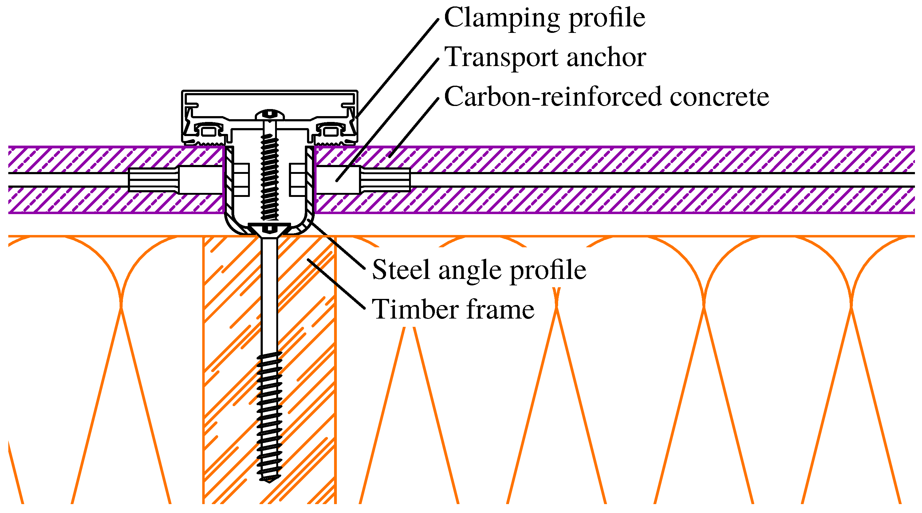
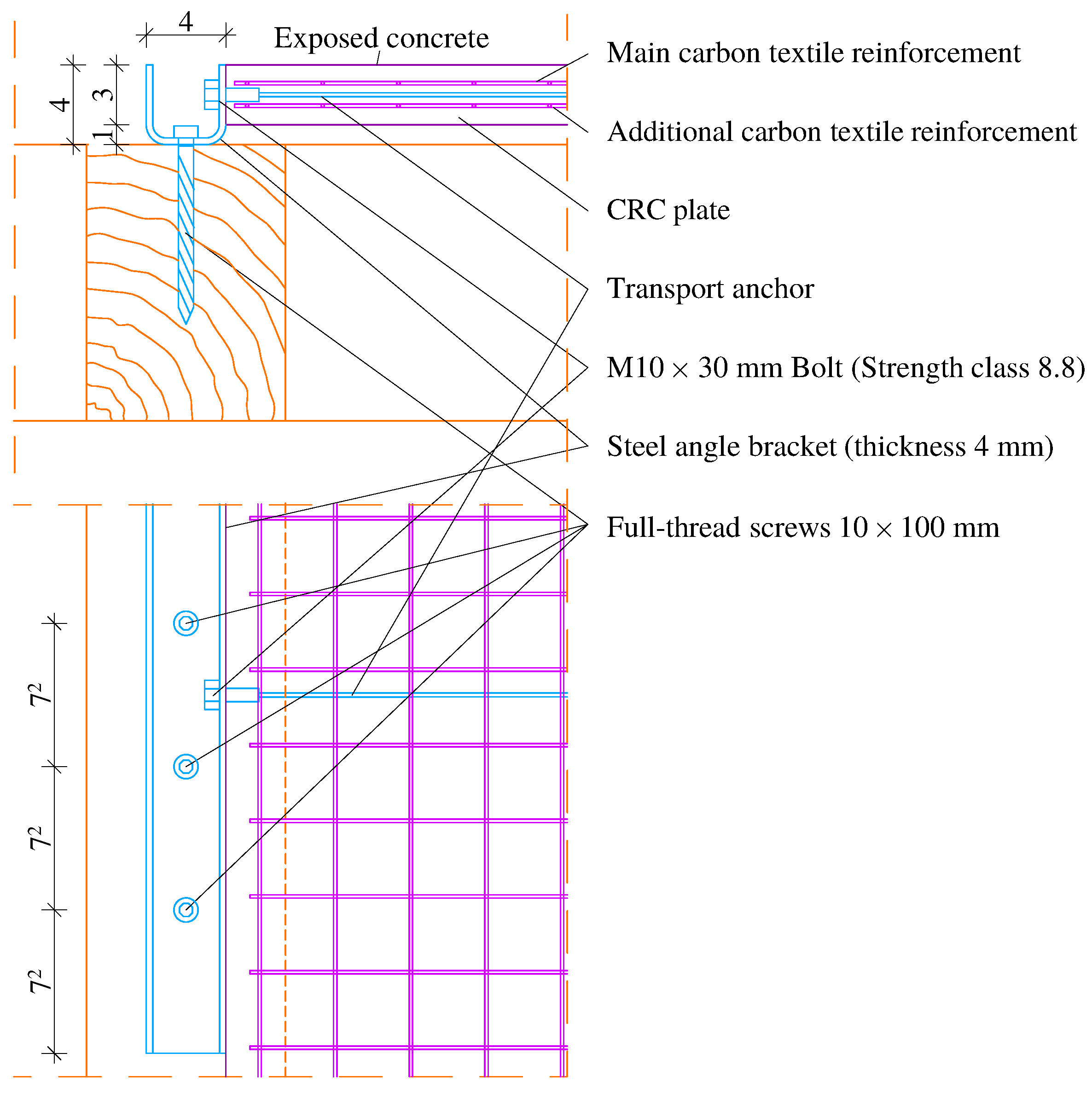
The investigated wall system consists of a load-bearing timber frame and an externally mounted carbon-reinforced concrete (CRC) plate. The timber frame forms the primary load-bearing substructure for vertical loads, while the CRC plate is intended to contribute to the in-plane shear response of the wall. Both subsystems are mechanically coupled along the vertical plate edges by individual connection points. The developed connection detail is shown in Figure 1.
The connection detail was developed for thin CRC plates, for which conventional through-fastening or deeply embedded connector solutions are not well suited. Through-fastening would disturb the exposed concrete surface and would reduce the architectural quality of the outer face. Deeply embedded connectors, in contrast, are difficult to realize in a plate thickness of only approximately 30 mm and would limit the design freedom of the thin CRC component. The adopted solution therefore uses transport anchors integrated into the plate edges as accessible embedded load-introduction points. Steel angle brackets are attached to these anchors and screwed to the timber frame, thereby forming the mechanical interface between the CRC plate and the timber structure.
A nominal clearance of 10 mm was intentionally provided between the rear side of the CRC plate and the timber frame. This clearance resulted from the use of 40 mm high steel angle brackets in combination with the 30 mm thick CRC plate. It was introduced to accommodate unavoidable surface irregularities of the casting side of the concrete plate and to avoid unintended contact, wedging, or constraint during assembly. Consequently, direct bearing or frictional load transfer between the CRC plate and the timber frame was not intended; the in-plane interaction was provided by the mechanical connection points.
The intended load path of the connection is therefore purely mechanical. In-plane shear forces are first transferred within the timber frame to the screwed steel angle brackets. From the timber frame, the forces are introduced through the full-thread screws into the steel angle brackets and then transferred by the M10 bolts into the embedded transport anchors. The transport anchors finally introduce the forces locally into the surrounding CRC plate in the anchorage zones, where the additional carbon textile reinforcement is intended to support local force transfer and crack control. Consequently, the structural response of the wall is governed not only by the global stiffness of the timber frame and the CRC plate, but also by the local load introduction at the six individual connection points and by the deformation capacity of the steel brackets.
In the present study, the transport anchors are not treated as conventional lifting devices for temporary handling only, but as experimentally investigated load-introduction elements within a reversible wall connection. Their suitability for permanent in-plane shear transfer is therefore not assumed a priori. Instead, the full-scale tests presented in this paper are used to assess whether the developed connection concept can transfer in-plane forces at component level and how local damage in the anchorage zones affects the global wall response.

3. Specimen Description and Structural System

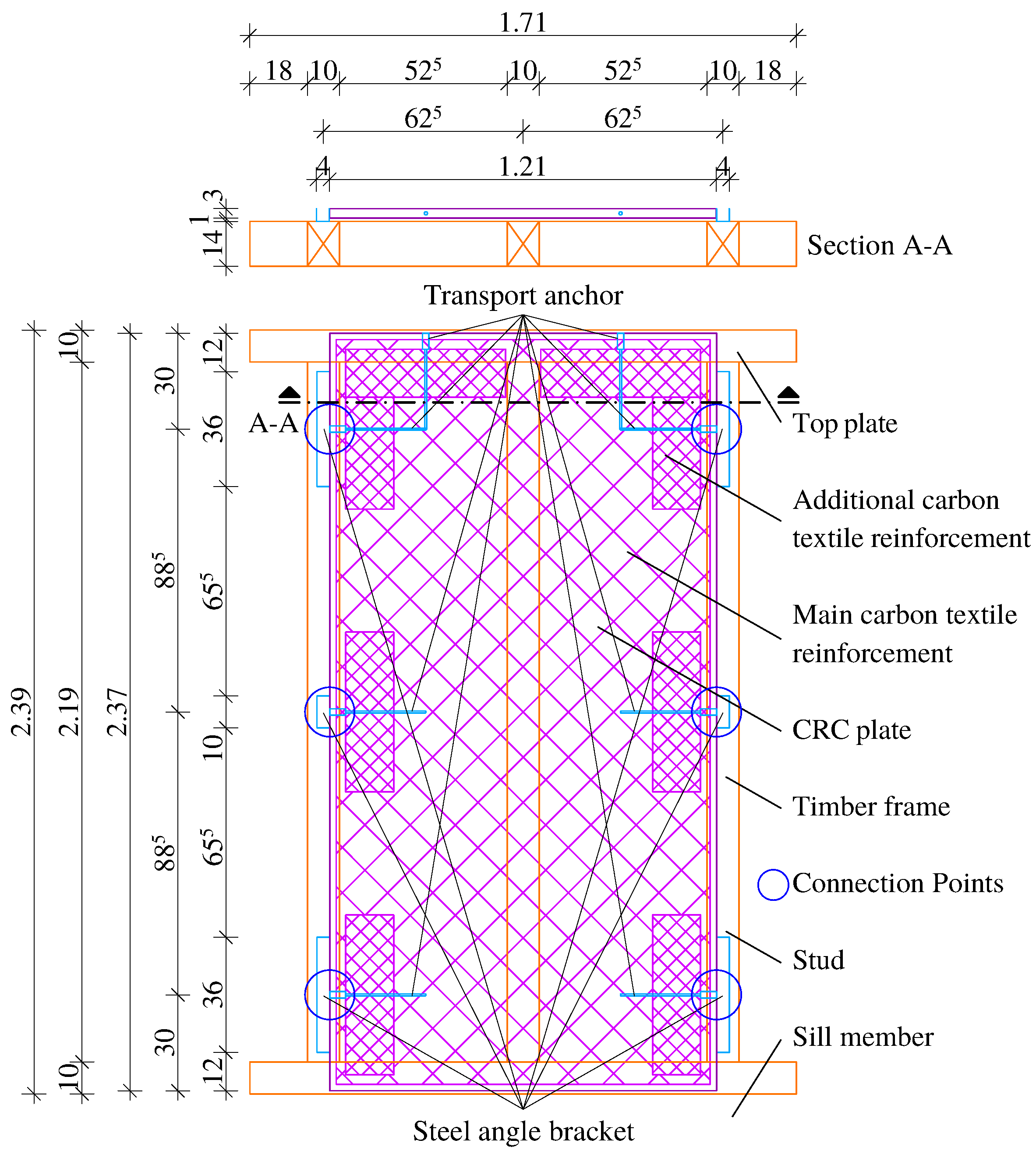
The experimental program comprised four identical full-scale wall specimens representing the developed hybrid timber–CRC wall system. Each specimen consisted of a timber frame and one externally mounted carbon-reinforced concrete (CRC) plate. The two subsystems were connected along the two vertical plate edges by six individual mechanical connection points. The overall geometry and the arrangement of the main components are shown in Figure 2, while the reversible mechanical connection is detailed in Figure 3.
The timber frame had an overall height of H = 2.39 m and an overall width of B = 1.71 m . It was composed of a continuous sill member, a continuous top plate, and vertical studs arranged at a spacing of a = 625 mm . The frame members had a cross-section of 100 × 140 mm . The studs were made of spruce structural solid timber, corresponding to the German product designation KVH in non-visible quality (NSi), whereas the sill member and the top plate were made of oak timber. No specimen-specific mechanical characterization was performed for the timber members. The larger frame width, compared with the width of the CRC plate, resulted from the overhang of the sill member and top plate beyond the outer studs in order to keep the timber corner joints unobstructed.
The CRC plate measured 1.21 m × 2.37 m and had a nominal thickness of 30 mm . It was produced from a fine-grained concrete matrix designed for a target strength class of C50/60 and reinforced with carbon textile grids. The main reinforcement consisted of solidian GRID Q47-CCE-38, while solidian GRID Q95-CCE-38 was additionally provided locally in the anchorage zones. The relevant manufacturer data of both carbon textile reinforcements are summarized in Table 1. These data are used for product identification and for the mechanical interpretation of the observed cracking and local anchorage-zone damage; the textile reinforcement itself was not tested separately within the present study.
The nominal mix composition of the fine-grained concrete matrix is summarized in Table 2. The small amount of quartz sand 0–1 mm was added intentionally to adjust the grading curve and to compensate for the comparatively low fine-particle content of the available sand fraction. In addition to the nominal mix composition, the relevant mechanical properties of the fine-grained concrete were determined at an age of 28 days. The flexural tensile strength was determined first on prismatic specimens with dimensions of 40 × 40 × 160 mm ; the resulting prism halves were subsequently used for compressive strength testing. The modulus of elasticity was determined on cylindrical specimens with a diameter of 100 mm and a height of 200 mm . The measured compressive strength, flexural tensile strength, and modulus of elasticity are summarized in Table 3. These values are used to characterize the concrete matrix of the CRC plates and to support the interpretation of the local damage observed in the anchorage zones.
Mechanical coupling between the timber frame and the CRC plate was realized by six steel angle brackets arranged exclusively along the two vertical plate edges, with three brackets per side. At each side, one long bracket was placed near the upper corner and one near the lower corner, while one shorter bracket was positioned at mid-height. No brackets were arranged along the top or bottom plate edges. The long brackets were made from structural steel sheet with a nominal U-shaped geometry of 40 × 40 × 4 mm and had a length of 350 mm ; the middle brackets had the same cross-section and a length of 150 mm . Since the bracket height of 40 mm exceeded the nominal CRC plate thickness of 30 mm , a planned clearance of approximately 10 mm remained between the rear side of the CRC plate and the timber frame. This clearance was intended to compensate for surface irregularities of the casting side of the CRC plate and to facilitate assembly without unintended contact between concrete and timber.
The brackets were connected to the CRC plate via integrated transport anchors and to the timber frame via screws. In total, six HALFEN HD-SL30 transport anchors were used as load-transferring connection points. In addition, two further anchors were installed in the CRC plate for handling and assembly purposes but were not part of the shear-transferring connection system. The steel brackets were fastened to the anchors by one M 10 × 30 mm bolt of strength class 8.8 per bracket. The corner brackets were connected to the timber frame by four HBS PLATE HBSPL10100 full-thread screws (Rothoblaas, Cortaccia, Italy) each, whereas the shorter middle brackets CP2 and CP5 were connected by one full-thread screw each. The main materials and connection components used for the specimens are summarized in Table 4.
The embedded anchors listed in Table 4 were HALFEN HD-SL30 socket lifting anchors (HALFEN GmbH, Langenfeld, Germany). According to the manufacturer’s technical product information, this anchor system was developed for thin fibre-reinforced precast concrete elements with a minimum element thickness of 30 mm and consists of a threaded sleeve and reinforcement bar made of stainless steel [54]. The anchor used in the present specimens corresponds to load class 0.8 with an M 10 internal thread, an external diameter of 14.1 mm , a total length of 300 mm , and a thread depth of 17 mm [54]. The exact stainless-steel grade as well as the yield strength and ultimate tensile strength of the embedded HD-SL30 anchors were neither determined experimentally nor specified in the product information available to the authors; therefore, these values are not used in the mechanical interpretation of the tests. For lifting applications, the manufacturer specifies load capacities of 8.0 kN for axial pull and 6.4 kN for diagonal pull up to 30 , provided that the concrete compressive strength is at least 50 N / mm 2 and the edge distance is 300 mm [54,55]. A related HALFEN FPA SL30 facade-panel anchorage system is covered by the German technical approval/general construction technique permit Z-21.8-2067 [56]. However, this approval does not cover the present use of HD-SL30 transport anchors as permanent in-plane shear-transferring connectors in a timber–CRC wall system. Therefore, the manufacturer and approval data are used here only for product identification, detailing context, and delimitation from approved facade-panel anchorage applications; the shear resistance of the investigated connection is derived exclusively from the experimental results presented in this study.
From a structural point of view, the tested specimen can be described as a mechanically coupled wall element in which the timber frame forms the primary load-bearing substructure and the externally mounted CRC plate acts as a connected stiffening component. The in-plane interaction between both subsystems was established solely through the six individual mechanical connection points along the vertical plate edges described above.

4. Experimental Setup and Test Protocol

4.1. Test Arrangement and Boundary Conditions

Because the wall specimens were tested in a horizontal position, the terms vertical and horizontal refer to the wall in its service orientation and not to the laboratory coordinate system of the test setup. The horizontal test arrangement was chosen because it allowed the large-scale wall specimens to be tested on the available reinforced concrete reaction floor with controlled anchorage and load introduction. A vertical racking test frame with comparable capacity and boundary-condition control was not available for the present test series. Consequently, the tests were designed as adapted full-scale in-plane shear tests rather than as conventional upright racking tests.
The full-scale wall specimens were tested in a horizontal position on a reinforced concrete reaction floor with integrated anchorage points. The test arrangement was developed to investigate the in-plane shear response of the wall elements under a nominally constant vertical preload combined with a gradually increasing horizontal load. The experimental procedure was based on the general evaluation principles of EN 594 [57] and ISO 21581 [58], while the setup and loading protocol were adapted to the specific geometry and connection concept of the investigated hybrid wall system.
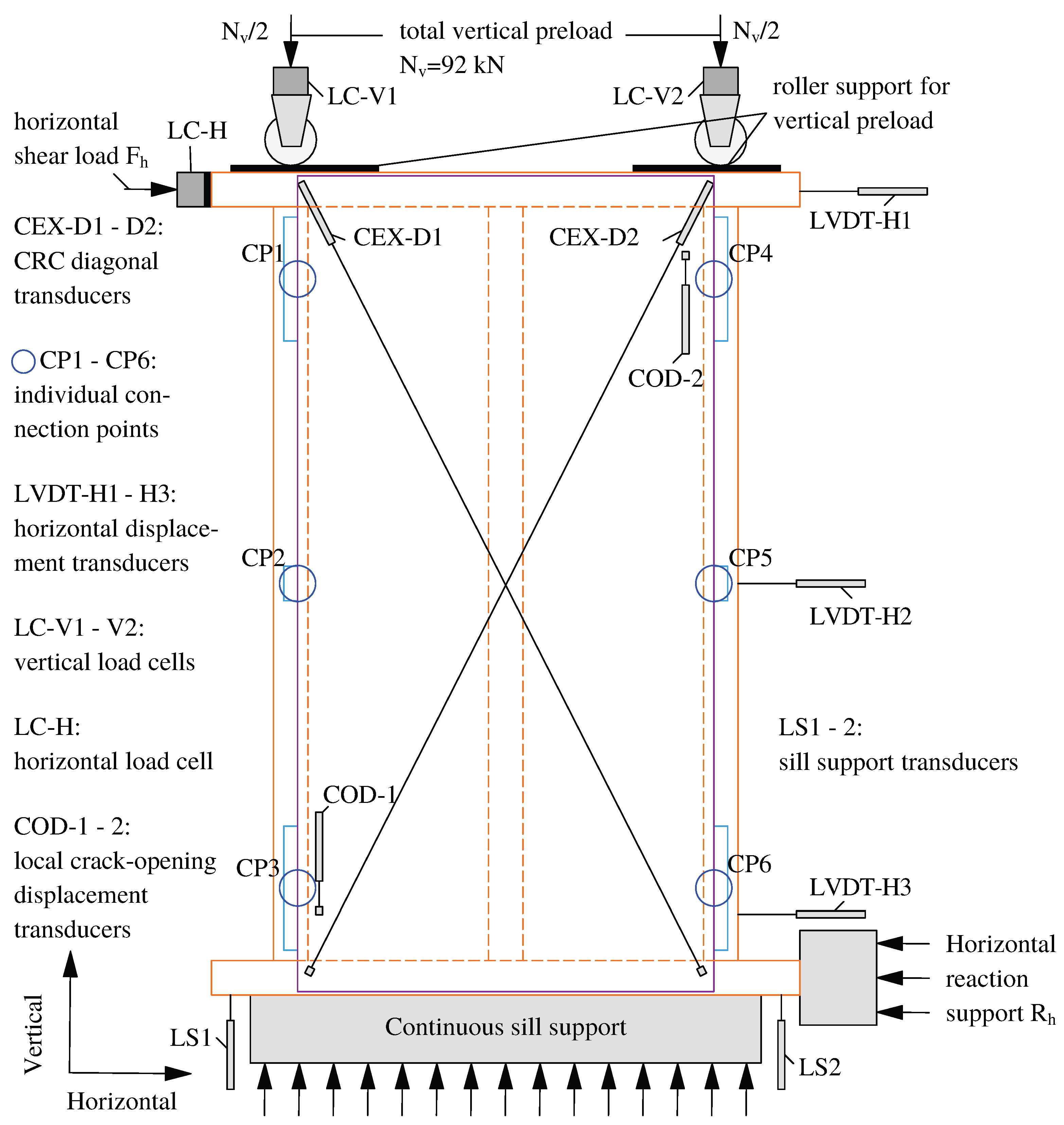
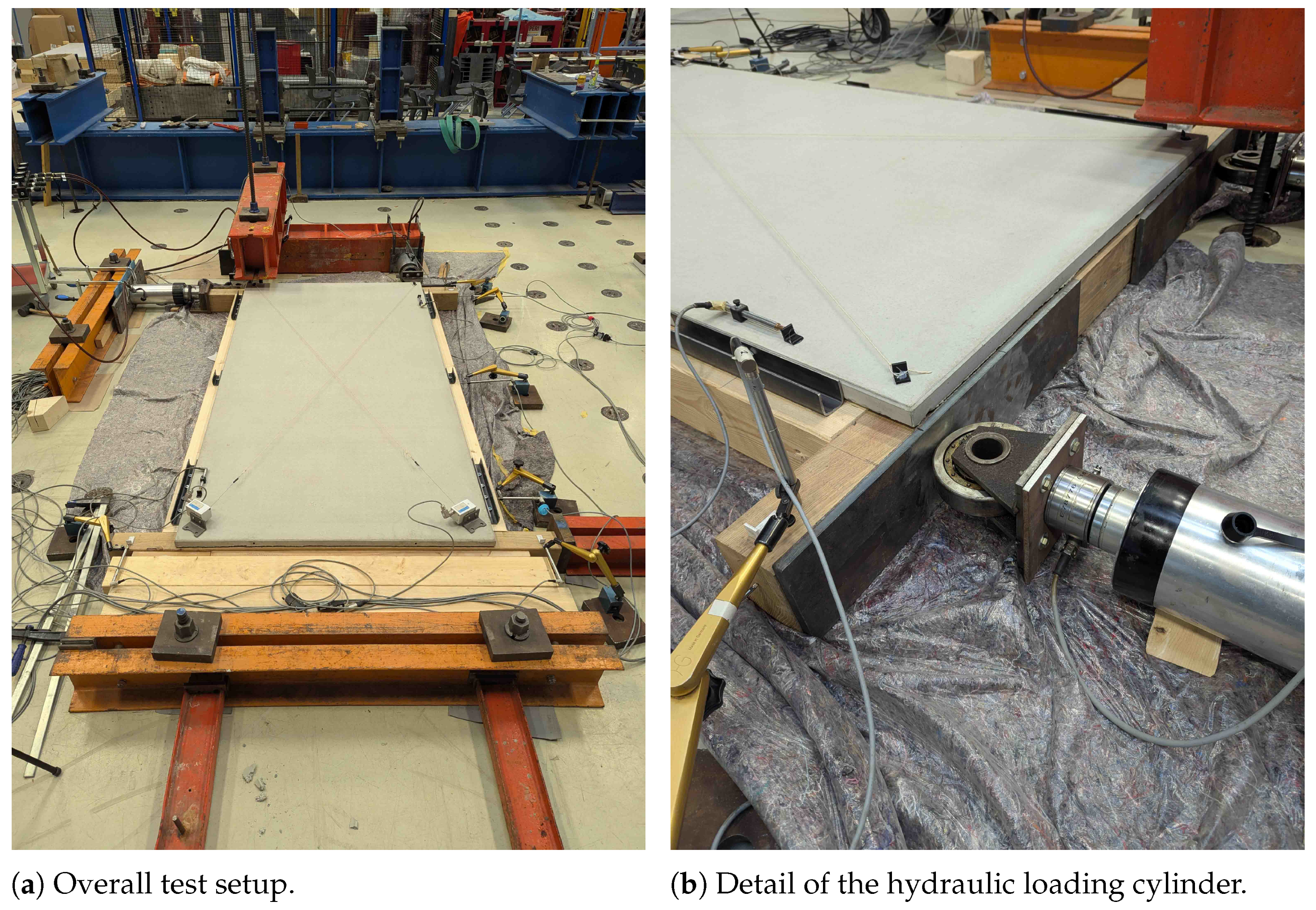
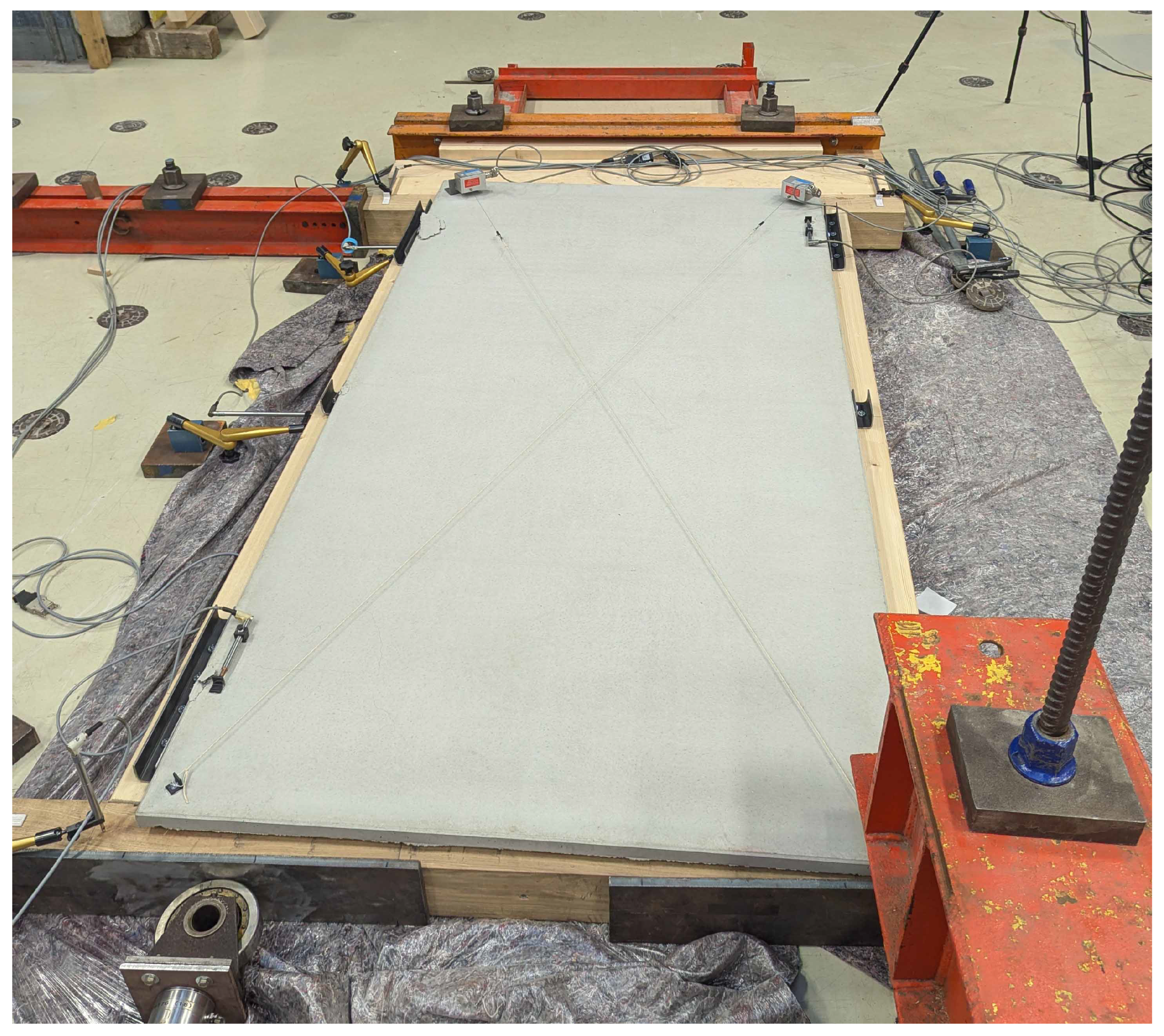
The specimens were supported at the sill member. In this region, the wall was fixed against horizontal displacement in the loading direction and against vertical downward movement by means of a continuous surface support. The specimen rested flat on the reaction floor on a foil–fleece interlayer in order to reduce friction and to minimize unintended restraint of the global deformation. The interlayer was used to reduce, but not completely eliminate, friction between the specimen and the support surface; the residual friction was not quantified separately. The test setup itself was braced against the anchorage points of the reaction floor. No additional out-of-plane stabilization was provided during testing. The full-scale test setup and the load-introduction detail are shown in Figure 4.
A nominally constant vertical preload of N v = 92 kN was applied to the top plate by two hydraulic loading cylinders in order to provide a stabilizing compressive force and to prevent premature uplift of the sill member during horizontal loading. The load introduction points were equipped with large roller bearings so that vertical loading could be maintained while allowing horizontal deformation of the specimen with minimal restraint. Steel plates were placed between the timber member and the roller bearings in order to prevent local indentation of the wood and to avoid deformation-induced constraint at the load introduction points.
The horizontal shear load was introduced by a third hydraulic loading cylinder directly into the projecting part of the top timber frame, acting in the longitudinal direction of the member. The line of action of the horizontal loading cylinder was aligned with the in-plane direction of the wall specimen and introduced at the level of the top timber member. Thus, the horizontal load was applied to the timber frame rather than directly to the CRC plate, and the force was transferred into the CRC plate only through the discrete bracket–anchor connections. Possible small eccentricities resulting from construction tolerances, the finite thickness of the wall build-up, or the offset between the load introduction into the timber frame and the mid-plane of the CRC plate were not measured separately and may have influenced the local force distribution between the connection points. The tests were carried out under load control. During the tests, small fluctuations of the vertical preload occurred as a result of increasing horizontal deformation and the manual hydraulic load control. The vertical forces were monitored continuously by the load cells at the two vertical cylinders and were manually readjusted when necessary in order to keep the preload close to the target value. The recorded preload variation is reported together with the test results.

4.2. Derivation of Vertical Preload and Estimated Maximum Load

The loading protocol required an estimated maximum horizontal load before the full-scale wall tests were carried out. This value is denoted as F max , est in the following and was used only to define the load levels of the preliminary loading cycles. It is therefore not a measured test result and must be distinguished from the experimentally determined maximum load F max .
The estimate was based on previous component-level tests on the selected connection concept. These tests were carried out on embedded transport anchors in thin carbon-reinforced concrete plates with comparable concrete matrix, carbon textile reinforcement, anchor type, and local load-introduction detail. In the relevant test series with one transport anchor and additional carbon textile reinforcement in the anchorage zone, a mean maximum load of approximately F conn , est = 20.3 kN was obtained [59]. This value was used as a simplified estimate of the load-carrying capacity of one effective connection point for the pre-test assessment. It was not used as a design resistance.
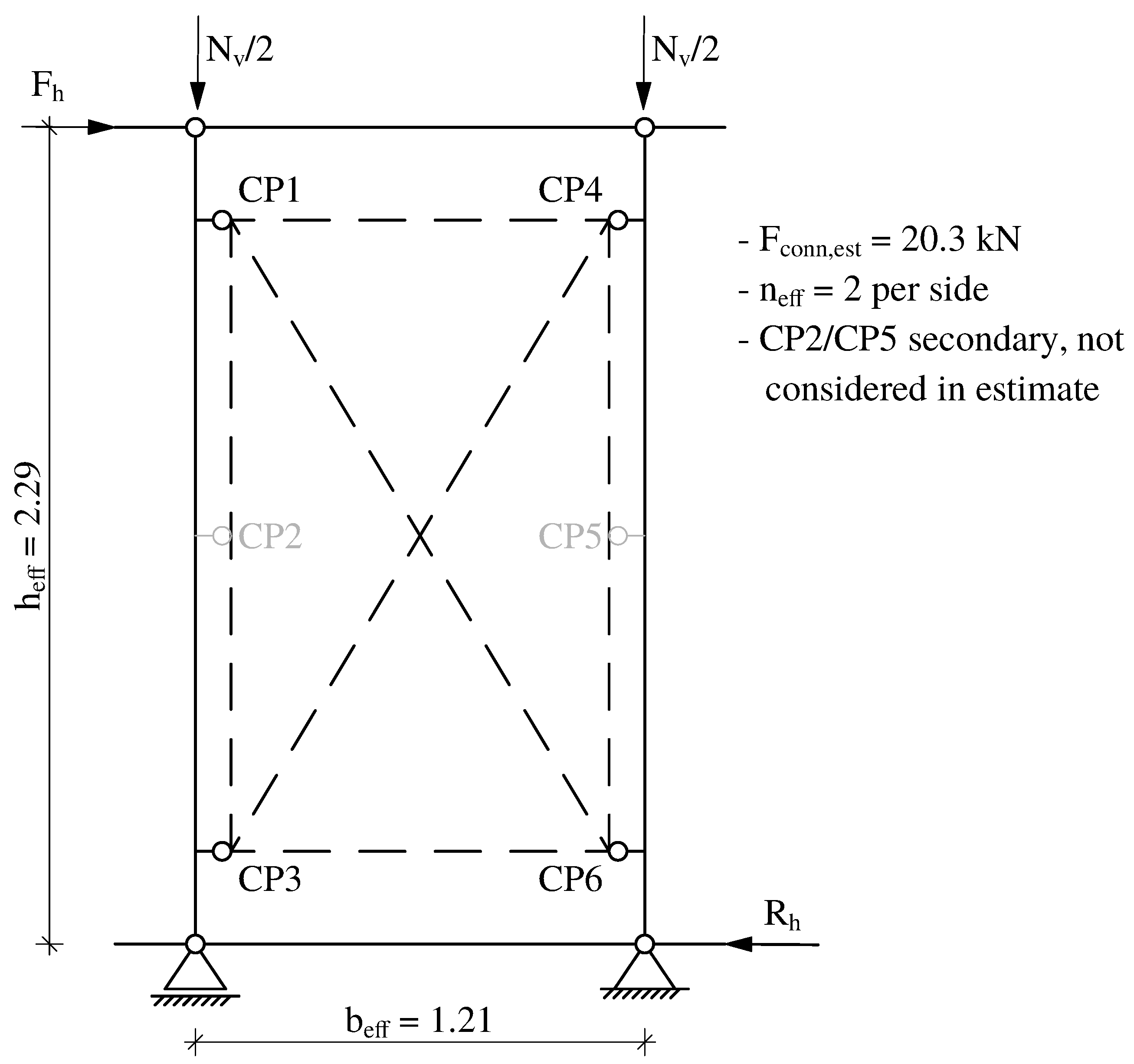
A simplified equilibrium model was then used to derive the expected maximum horizontal load of the wall specimen, see Figure 5. The horizontal load F h was assumed to generate an overturning moment over the effective height h eff = 2.29 m . This moment was assumed to be resisted by a force couple between the connection points along the two vertical plate edges. The effective lever arm of this force couple was taken as the effective plate width b eff = 1.21 m . For this estimate, only the two corner connection points per side were considered as effective. The middle connection points CP2 and CP5 were not included in the estimate, because they were primarily introduced to reduce the free edge length of the CRC plate and were connected to the timber frame by only one full-thread screw each. They were therefore expected to be considerably more flexible than the corner connection points.
With n eff = 2 effective connection points per side, the estimated maximum horizontal load was calculated from moment equilibrium as
F max , est = n eff · F conn , est · b eff h eff .
Substitution of the assumed values gives
F max , est = 2 · 20.3 kN · 1.21 m 2.29 m = 21.5 kN .
The vertical preload was then selected to prevent premature uplift of the sill member during horizontal loading. For this purpose, a second simplified moment equilibrium was considered. The stabilizing moment provided by the vertical preload was related to the lever arm b eff / 2 , resulting in the minimum required vertical preload
N v , min = F max , est · h eff b eff / 2 .
Using the estimated maximum horizontal load gives
N v , min = 21.5 kN · 2.29 m 1.21 m / 2 = 81.2 kN .
For the full-scale tests, the vertical preload was rounded up and set to
N v = 92 kN .
This corresponds to a margin of approximately 13 % relative to the calculated minimum value. The preload was applied by two hydraulic cylinders and was therefore introduced as N v / 2 = 46 kN at each load introduction point. The value was chosen to provide a stable boundary condition for the in-plane shear test and to avoid premature uplift of the sill member. It should therefore be understood as a test-specific stabilizing preload rather than as a complete representation of all vertical actions in a building.

4.3. Loading Protocol

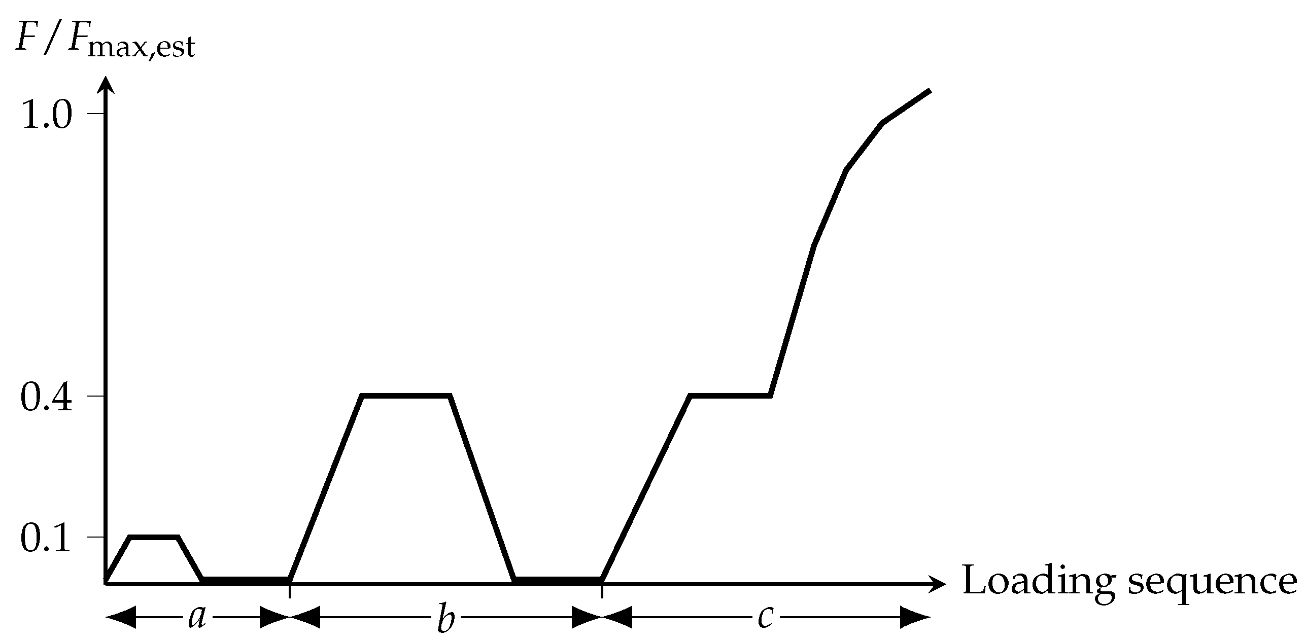
The loading protocol followed a staged procedure based on the estimated maximum horizontal load F max , est . With F max , est = 21.5 kN , the preliminary load levels corresponded to approximately 2.2 kN and 8.6 kN . First, an initial loading cycle up to approximately 0.1 F max , est was applied, followed by a hold time of 120 s and a recovery period of 600 s . Subsequently, a second loading cycle up to approximately 0.4 F max , est was carried out, followed by a hold time of 300 s and a recovery period of 600 s . After these preliminary loading cycles, the specimens were loaded again to approximately 0.4 F max , est , held for 300 s , and then loaded continuously until failure. The test was terminated when a clear failure state had developed after the maximum load had been passed, or when a horizontal head displacement of 100 mm was reached. The schematic loading protocol is shown in Figure 6.

4.4. Instrumentation and Evaluation Quantities

The experimental instrumentation comprised force and displacement measurements at both global and local level (the arrangement is shown in Figure 7). The horizontal load was recorded by the load cell LC-H, while the vertical preload was recorded by the two load cells LC-V1 and LC-V2 at the vertical hydraulic cylinders. The global deformation of the timber frame was measured by inductive displacement transducers LVDT-H1 to LVDT-H3 arranged at different positions over the specimen height. In addition, uplift or vertical movement of the sill member at the left and right boundary zones was monitored by the displacement transducers LS1 and LS2. The deformation of the CRC plate was recorded along both diagonals by the cable-extension transducers CEX-D1 and CEX-D2 in order to capture the global in-plane deformation of the plate. Furthermore, local crack-opening displacements in selected anchorage zones were measured by inductive displacement transducers COD-1 and COD-2 placed across the expected crack path. The sensor types, nominal measuring ranges, and relevant manufacturer specifications are summarized in Table 5.
For the evaluation of the wall response, the horizontal head displacement was used as the governing deformation quantity. Based on the recorded global horizontal load–head displacement curves of the wall specimens, the maximum horizontal load F max and characteristic wall stiffness values were determined. In accordance with the evaluation approach of EN 594 and ISO 21581, the wall stiffness was determined from the global load–displacement curve between the load levels 0.2 F max and 0.4 F max . Because the test setup was adapted to a horizontal arrangement and to the specific hybrid wall configuration, the stiffness values are used as global comparative wall stiffness values. They should not be understood as the result of a complete standardized EN 594 wall test.

5. Results and Discussion

5.1. Global Load–Displacement Response and Preload Stability

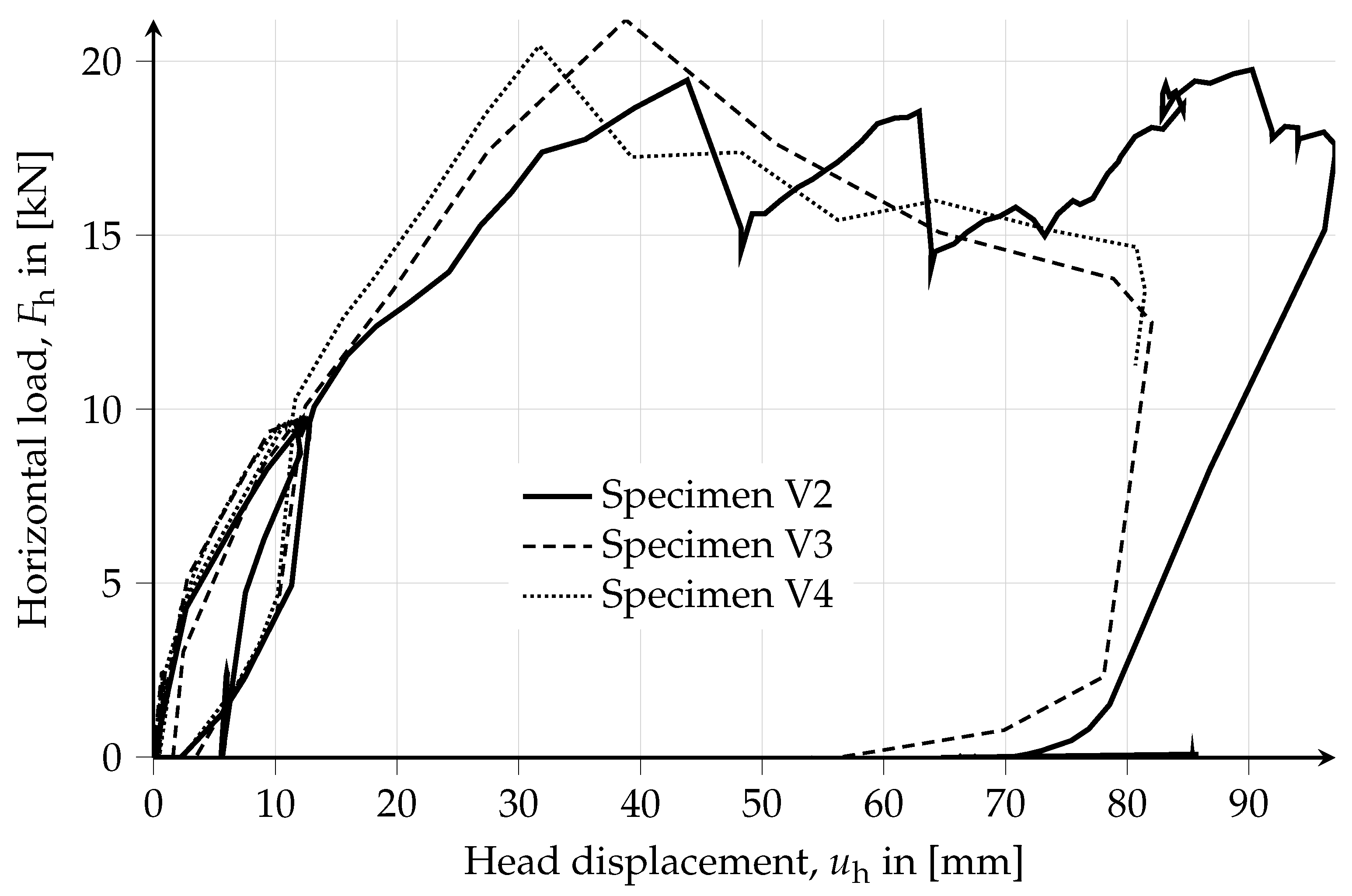
The global response of the tested wall specimens was characterized by uniform load–displacement behavior. Complete displacement data were available for specimens V2, V3, and V4, whereas the displacement recording of specimen V1 was incomplete due to a measurement failure. However, specimen V1 showed a comparable damage pattern and reached a maximum load in the same range as the other tests. The load–displacement curves of specimens V2 to V4 are shown in Figure 8. The maximum horizontal loads ranged from 19.7 to 22.7 kN . For the specimens with complete displacement data, the head displacement at maximum load ranged from 33.7 to 45.8 mm .
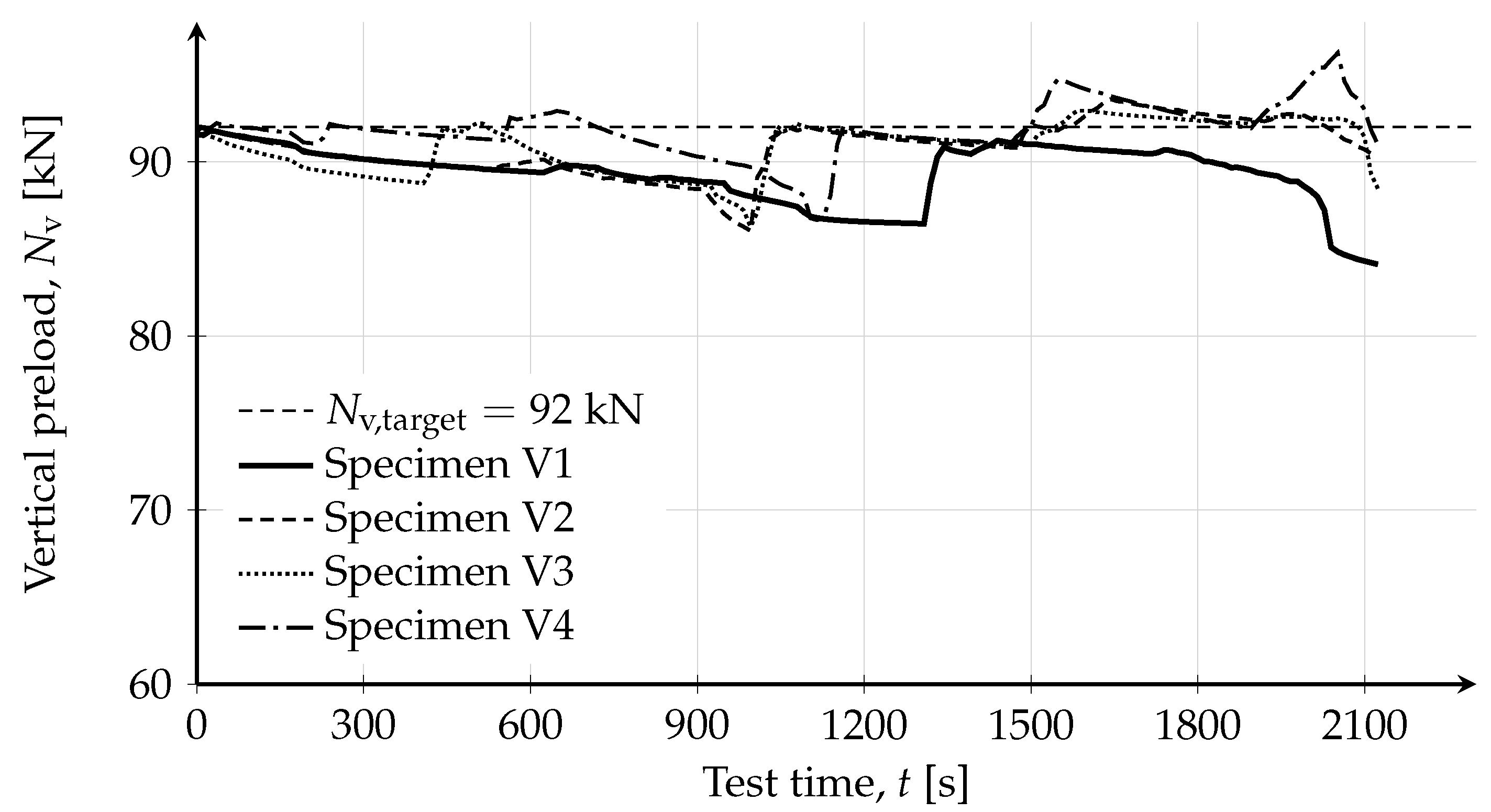
The recorded vertical preload remained close to the target value of N v = 92 kN . Across the test series, the preload varied between 86 and 94 kN , corresponding to a maximum deviation of approximately 7 % from the target value. Minor variations occurred during increasing horizontal deformation and were caused by the interaction between specimen deformation and the manually controlled hydraulic loading system. The comparable preload histories confirm that the specimens were tested under similar vertical boundary conditions. The recorded vertical preload histories are shown in Figure 9.
The measured curves exhibit an initially increasing but distinctly nonlinear response. Even before the first pronounced load drop, the stiffness decreased progressively with increasing load level. After reaching the maximum load, a marked load drop occurred, indicating the onset of local damage in the connection zones. With further increasing head displacement, the load increased again, although the previously attained maximum load was not reached anymore. This behavior occurred repeatedly and resulted in a characteristic saw-tooth-shaped post-peak response. The global behavior therefore shows that local damage events did not immediately lead to a loss of overall load-bearing capacity. The repeated post-peak load recovery is consistent with the continued activation of remaining load-transfer mechanisms within the wall system.

5.2. Maximum Load, Stiffness, and Repeatability

Two stiffness values were evaluated to characterize the nonlinear wall response. The stiffness K 0.2 0.4 follows the evaluation range commonly used in EN 594 and ISO 21581, whereas K 0.05 0.15 was additionally introduced to quantify the initial stiffness in the lower load range. Both stiffness values were derived from the global horizontal load–head displacement relationship and therefore represent wall specimen stiffness rather than the local stiffness of the individual connection devices:
K 0.2 0.4 = F 4 F 2 v 4 v 2 ,
where F 2 = 0.2 F max , F 4 = 0.4 F max , and v 2 and v 4 are the corresponding head displacements. In addition, a second wall stiffness value was evaluated in the lower load range between 0.05 F max and 0.15 F max in order to describe the pronounced initial nonlinearity of the response:
K 0.05 0.15 = F 0.15 F 0.05 v 0.15 v 0.05 ,
where F 0.05 = 0.05 F max , F 0.15 = 0.15 F max , and v 0.05 and v 0.15 are the corresponding head displacements.
The comparison of both stiffness values shows that the wall response was already nonlinear in the early loading stage. The stiffness in the range 0.05 F max to 0.15 F max was consistently higher than the EN 594-related stiffness evaluated between 0.2 F max and 0.4 F max . This confirms the progressive stiffness reduction that is visible in the global load–displacement curves before the maximum load is reached. The characteristic test results of the investigated wall specimens are summarized in Table 6.
For specimen V1, the horizontal load signal recorded by load cell LC-H was available throughout the test, so that the maximum horizontal load F max = 20.9 kN could be determined. However, the displacement recording for this specimen was incomplete. Consequently, V1 was included only in the evaluation of the maximum horizontal load and the visually observed failure mode, but was excluded from all displacement-dependent quantities, including the head displacement at maximum load and the stiffness values K 0.05 0.15 and K 0.2 0.4 . The maximum horizontal load showed a mean value of 21.2 kN and a coefficient of variation of 5.9 % , indicating low scatter in load-bearing capacity within the limited test series. The displacement-dependent quantities showed larger scatter, particularly the head displacement at maximum load and the initial stiffness, which reflects the pronounced nonlinear response and the sensitivity of the early deformation range.
The experimentally determined maximum loads were close to the pre-test estimate F max , est = 21.5 kN . This confirms that the simplified estimate was suitable for defining the preliminary loading levels, but it should not be interpreted as validation of a general design model.
Within the scope of the present series, the investigated wall configuration showed low scatter in maximum horizontal load and a comparable governing failure mode. The larger scatter in displacement-dependent quantities is attributed to the nonlinear deformation behavior and the progressive local damage development before and after the maximum load.

5.3. Damage Evolution and Local Crack Opening

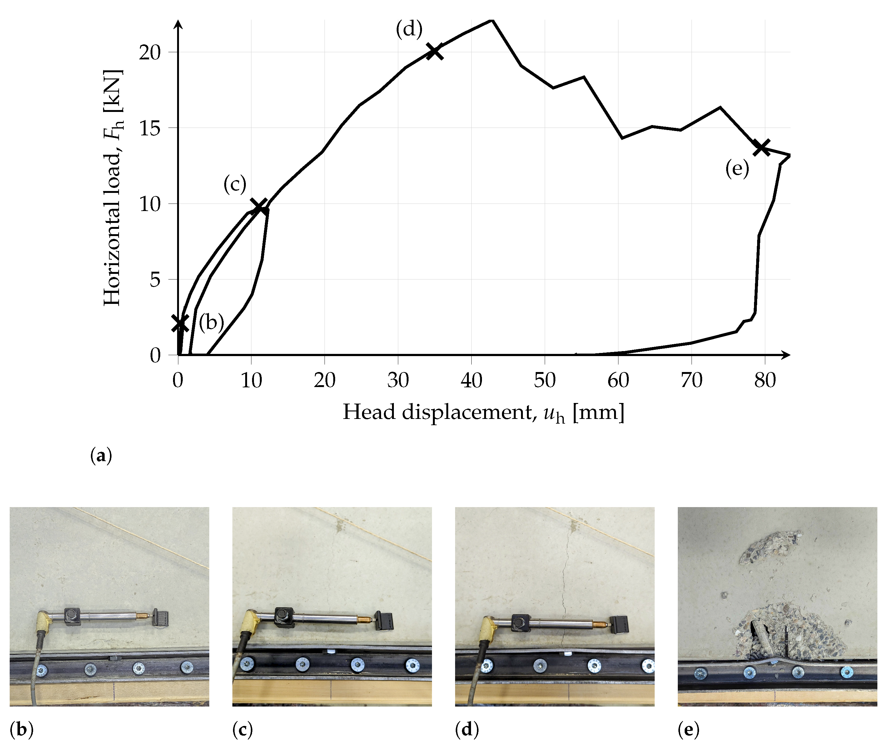
The observed damage development was similar in all four tests. First visible cracks occurred in the CRC plate in the anchorage zones of the embedded transport anchors. These cracks initiated at the plate edge and propagated toward the plate interior. In particular, the corner anchors were affected first. With increasing horizontal deformation, crack length and crack width increased continuously. At later stages of loading, comparable cracking was also observed at the middle anchors. The initially local cracks gradually developed into more pronounced damage zones. Only at larger displacements, typically after renewed temporary load increases in the post-peak range, did local concrete spalling occur, with concrete fragments detaching above or below the anchorage zone.
A representative load–displacement curve of specimen V3 with the corresponding damage stages is presented in Figure 10. The sequence illustrates the transition from first cracking at the corner anchors to progressive crack growth and finally to local concrete spalling. The correlation between the local damage events and the repeated load drops supports the interpretation that the post-peak response was governed by successive local failures of individual connection zones rather than by a sudden global collapse of the wall specimen.
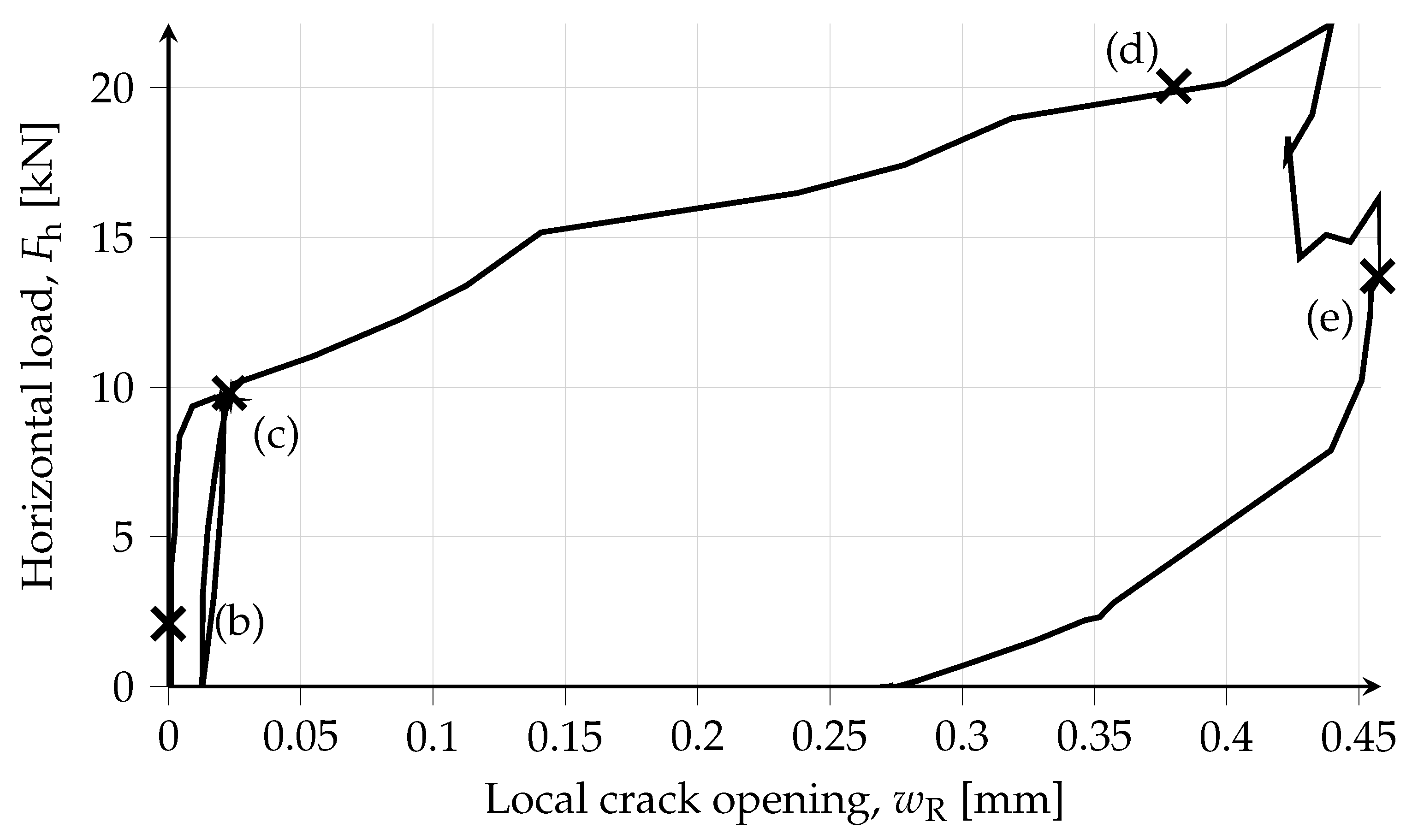
The local crack opening measurements in the anchorage zone of a representative corner anchor, shown in Figure 11, further support this interpretation. The recorded crack opening increased nonlinearly with head displacement and exhibited distinct increments associated with the observed local damage progression. These local measurements support the interpretation of a progressive failure process in the CRC anchorage zones.
For specimen V3, the local crack opening increased from an initially negligible value to approximately 0.37 mm near the maximum load and reached approximately 0.45 mm in the post-peak range. The stepwise increase in crack opening coincided with the visually observed crack growth and with load drops in the global load–displacement curve.

5.4. Failure Mode and Mechanical Interpretation

The governing failure mode of the tested wall specimens was a local concrete failure in the anchorage zones of the CRC plate. In addition, noticeable deformations of the steel angle brackets were observed in the connection region between the bracket and the plate. As local concrete damage progressed and the anchor tip became exposed, the anchor was able to rotate locally, which in turn caused bending of the connected steel bracket. On the timber side, a pronounced global deformation of the frame was observed, including a visible displacement of the top plate and an inclined position of the studs. Nevertheless, no relevant damage was detected in the timber joints themselves.
All bracket–anchor connections were arranged only along the two vertical edges of the CRC plate. This edge-based connector layout may introduce additional bending of the CRC plate, because the horizontal load is transferred through discrete edge connections rather than through a continuous or more uniformly distributed connection system. In addition, the discrete load introduction can cause local stress concentrations at the connection points. Both effects are limitations of the tested configuration, since neither local plate bending nor local stress distributions were measured directly.
Mechanically, the horizontal load introduced into the top member generated an overturning moment that was resisted by a force couple between the connection zones along the two vertical edges of the CRC plate. This load path preferentially activated the corner connection points, whereas the middle connection points mainly reduced the free edge length of the CRC plate and were expected to participate with lower stiffness because of their shorter brackets and reduced screw connection. Consequently, local rotation of the exposed anchors and bending of the steel brackets concentrated the demand in the thin CRC anchorage zones, which is consistent with the observed cracking and spalling at the corner anchors. The overall deformation state after testing is shown in Figure 12.
Overall, the tested wall system did not fail in a brittle global manner. Instead, the response was governed by progressive local damage in the anchorage zones, accompanied by repeated load drops, subsequent load recovery, and continued load transfer within the recorded displacement range. This behavior suggests that the wall retained load-transfer capacity after the onset of local damage. Since individual connector forces were not measured directly, possible redistribution between connection zones should be understood as an interpretation based on the global post-peak load recovery, the local crack-opening measurements, and the visual damage observations.

5.5. Limitations of the Experimental Series

The significance of the present findings is limited to the investigated configuration. All specimens had the same geometry, the same connection layout, the same material configuration, and were tested under the same nominal vertical preload. The experiments were carried out under quasi-static loading and do not provide information on the influence of alternative geometries, modified anchor arrangements, different preload levels, cyclic loading histories, long-term loading, or environmental actions. The results therefore allow an assessment of the response and failure behavior of the tested wall system, but they do not yet provide a general design basis for other system variants or boundary conditions.
In addition, the tests were carried out in a horizontal arrangement on a reaction floor rather than in an upright wall test setup. This adapted arrangement was necessary due to the available laboratory infrastructure, but it affects the boundary conditions of the experiment. In particular, the self-weight of the CRC plate and timber frame acted differently from an upright wall configuration, and the support on the reaction floor may have introduced residual friction despite the use of a foil–fleece interlayer. This residual friction was not quantified separately and may have contributed slightly to the measured horizontal resistance. Moreover, the horizontal setup does not fully reproduce the support conditions, load transfer mechanisms, and gravity-related effects of an installed vertical wall element. Therefore, the results should be interpreted as component-level results for the adapted test configuration, and comparisons with upright wall tests should be understood as comparative classification rather than direct validation.
Furthermore, the force distribution between individual connection points and the relative displacement between the timber frame and the CRC plate at the mechanical connection points were not measured directly. Statements regarding possible redistribution between connection zones are therefore based on the combined interpretation of global load–displacement response, local crack-opening measurements, and visual damage observations.

5.6. Comparison with Related Experimental Results

To place the present results in context, a comparison with selected experimental studies on timber-based wall elements subjected to in-plane loading is useful. For this purpose, the studies by Grossi et al. [63,64] and Dobeš et al. [65] were selected, because they report wall tests with a focus on horizontal load-bearing capacity and wall stiffness and are therefore suitable as reference cases for a first comparison.
A direct comparison is, however, only possible to a limited extent. The investigated wall systems differ in material composition, connection concept, specimen geometry, and loading conditions. In addition, the cited studies tested the wall specimens in an upright position, whereas the present wall specimens were tested in a horizontal position. This difference in test arrangement affects the support conditions and the contribution of self-weight and therefore reduces the direct comparability and the general validity of the comparison. The values discussed below should therefore be understood as a comparative classification rather than as a direct performance ranking.
For the present wall system, the comparison is based on the maximum horizontal load and on the wall stiffness determined from the global load–head displacement curve according to EN 594. To account for differences in specimen size, the maximum load and the wall stiffness were related to the reference width of b ref = 1.25 m used for the present wall configuration. This reference width corresponds to the modular width used for the investigated wall configuration and was therefore selected for normalization of the own test results. Based on the three specimens with complete displacement data (V2–V4), the present test series yielded maximum horizontal loads of 15.8 to 18.2 kN / m and wall stiffness values K 0.2 0.4 of 0.42 to 0.54 kN / ( mm · m ) .
Table 7 summarizes the comparison with the selected reference studies. The tests by Grossi et al. provide a useful benchmark for timber-frame shear walls tested according to comparable in-plane loading principles, while the study by Dobeš et al. offers a recent reference for wall panels with experimentally determined horizontal load-bearing capacity and stiffness. Compared with these studies, the present wall system can be interpreted as a mechanically coupled hybrid wall with moderate in-plane load-bearing capacity and moderate wall stiffness, while at the same time showing a progressive failure process with repeated post-peak load recovery. In this respect, the results do not indicate an unusually high racking capacity, but they do show that the investigated reversible timber–CRC wall concept was able to maintain in-plane load transfer after the onset of local damage in the tested configuration.
The comparison also highlights that the measured wall stiffness of the present system should be interpreted as a global property of the wall specimen rather than as a local property of the individual connection devices. This is particularly important for the investigated configuration, because the response was governed by the combined deformation of the timber frame and the CRC plate. The progressive reduction in stiffness with increasing load, as discussed in the previous subsection, is therefore consistent with the observed local damage development and with the overall behavior of a mechanically coupled wall element.

6. Conclusions

This paper presented an experimental study on a demountable hybrid timber–carbon-reinforced concrete (CRC) wall system with a mechanically coupled connection detail based on embedded transport anchors, screwed steel angle brackets, and full-thread screws. Four full-scale wall specimens were tested under adapted in-plane shear loading with a nominally constant vertical preload. The objective was to evaluate the global shear response, the repeatability of the tested configuration, and the governing failure mechanism of the reversible connection concept.
  • The tested wall specimens showed a comparable global load–displacement response. The maximum horizontal loads ranged from 19.7 to 22.7 kN , with a mean value of 21.2 kN and a coefficient of variation of 5.9 % . The experimentally determined maximum loads were close to the pre-test estimate F max , est = 21.5 kN , indicating that the simplified estimate was suitable for defining the preliminary loading levels. This agreement should not be interpreted as validation of a general design model, but it supports the suitability of the estimate for the experimental procedure used in this study.
  • The global response was distinctly nonlinear. For the specimens with complete displacement data, the head displacement at maximum load ranged from 33.7 to 45.8 mm . The initial wall stiffness K 0.05 0.15 ranged from 1.93 to 2.80 kN / mm , whereas the stiffness evaluated between 0.2 F max and 0.4 F max ranged from 0.52 to 0.67 kN / mm . The comparison of these stiffness ranges confirms a pronounced stiffness reduction already before the maximum load was reached.
  • The governing failure mode was local concrete failure in the anchorage zones of the CRC plate. Cracking initiated at the embedded transport anchors, especially at the corner anchors, and propagated progressively with increasing deformation. At larger displacements, local concrete spalling occurred. Deformation of the steel angle brackets was also observed, whereas no critical damage was detected in the timber joints. The tests therefore indicate that the timber frame remained effective while the global response was governed primarily by the local load introduction into the CRC plate.
  • The tested wall system did not fail by sudden global collapse. Instead, the response was characterized by local damage events, repeated load drops, and partial post-peak load recovery. This indicates that the wall retained load-transfer capacity after the onset of local damage within the recorded displacement range. Since individual connector forces were not measured directly, possible redistribution between connection zones should be understood as an interpretation based on the global post-peak load recovery, local crack-opening measurements, and visual damage observations.
  • Compared with selected timber-based wall systems tested under in-plane loading, the investigated wall system achieved a moderate level of load-bearing capacity and wall stiffness. When normalized to the reference width of the tested configuration, the maximum horizontal load ranged from 15.8 to 18.2 kN / m and the wall stiffness K 0.2 0.4 ranged from 0.42 to 0.54 kN / ( mm · m ) . The comparison should be interpreted with caution because the reference studies differed in wall system, geometry, connection concept, and test arrangement. Nevertheless, the results show that the investigated reversible timber–CRC wall concept was able to maintain in-plane load transfer after the onset of local damage in the tested configuration.
  • The conclusions are limited to the investigated configuration. All specimens had the same geometry, connection layout, material configuration, and nominal vertical preload. In addition, the tests were carried out in a horizontal arrangement on a reaction floor, and residual friction at the support interface was reduced by a foil–fleece interlayer but not quantified separately. The results therefore provide an experimental assessment of the tested wall system, but they do not yet constitute a general design basis for other configurations or boundary conditions.
  • Further work should address modified connection layouts, different vertical preload levels, direct measurement of local relative displacements and connector forces, upright test arrangements, cyclic and long-term loading, and environmental exposure. These investigations are required to develop mechanically validated design recommendations for reversible timber–CRC wall systems using embedded transport anchors as shear-transferring connection elements.

Author Contributions

Conceptualization, M.S.; methodology, M.S., L.S. and T.K.; investigation, L.S. and M.S.; data curation, L.S. and M.S.; formal analysis, M.S. and L.S.; visualization, L.S. and M.S.; writing—original draft preparation, M.S.; writing—review and editing, All; supervision, M.S. and K.H. All authors have read and agreed to the published version of the manuscript.

Funding

This research was funded by the German Federal Ministry of Education and Research (BMBF) within the funding programme “KMU-innovativ–Ressourceneffizienz” in the joint project “KikE—Kreislaufgerechtes Bauen in klimaneutraler Elementbauweise”, grant number 033RK111D. The project was supervised by Projektträger Jülich (PTJ).

Institutional Review Board Statement

Not applicable.

Informed Consent Statement

Not applicable.

Data Availability Statement

The data presented in this study are available on request from the corresponding author.

Acknowledgments

During the preparation of this manuscript, the authors used OpenAI’s ChatGPT (GPT-5.4 Thinking) for language editing, text structuring, and formulation support. The authors reviewed and edited the output and take full responsibility for the content of this publication.

Conflicts of Interest

The authors declare no conflicts of interest. The funders had no role in the design of the study; in the collection, analyses, or interpretation of data; in the writing of the manuscript; or in the decision to publish the results.

Abbreviations

The following abbreviations are used in this manuscript:
CRCCarbon-reinforced concrete
DfDDesign for Disassembly

References

  1. Mrad, C.; Frölén Ribeiro, L. A Review of Europe’s Circular Economy in the Building Sector. Sustainability 2022, 14, 14211. [Google Scholar] [CrossRef]
  2. Finamore, M.; Oltean-Dumbrava, C. Circular economy in construction—Findings from a literature review. Heliyon 2024, 10, e34647. [Google Scholar] [CrossRef]
  3. Andersen, C.E.; Kanafani, K.; Zimmermann, R.K.; Rasmussen, F.N.; Birgisdóttir, H. Comparison of GHG emissions from circular and conventional building components. Build. Cities 2020, 1, 379–392. [Google Scholar] [CrossRef]
  4. Küpfer, C.; Bertola, N.; Brütting, J.; Fivet, C. Decision Framework to Balance Environmental, Technical, Logistical, and Economic Criteria When Designing Structures With Reused Components. Front. Sustain. 2021, 2, 689877. [Google Scholar] [CrossRef]
  5. Rios, F.C.; Chong, W.K.; Grau, D. Design for Disassembly and Deconstruction–Challenges and Opportunities. Procedia Eng. 2015, 118, 1296–1304. [Google Scholar] [CrossRef]
  6. Ostapska, K.; Rüther, P.; Loli, A.; Gradeci, K. Design for Disassembly: A systematic scoping review and analysis of built structures Designed for Disassembly. Sustain. Prod. Consum. 2024, 48, 377–395. [Google Scholar] [CrossRef]
  7. O’Grady, T.; Minunno, R.; Chong, H.Y.; Morrison, G.M. Design for Disassembly, Deconstruction and Resilience: A Circular Economy Index for the Built Environment. Resour. Conserv. Recycl. 2021, 175, 105847. [Google Scholar] [CrossRef]
  8. Munaro, M.R.; Tavares, S.F. Design for Adaptability and Disassembly: Guidelines for Building Deconstruction. Constr. Innov. 2025, 25, 665–687. [Google Scholar] [CrossRef]
  9. Ottenhaus, L.M.; Yan, Z.; Brandner, R.; Leardini, P.; Fink, G.; Jockwer, R. Design for adaptability, disassembly and reuse—A review of reversible timber connection systems. Constr. Build. Mater. 2023, 400, 132823. [Google Scholar] [CrossRef]
  10. Yeoh, D.; Fragiacomo, M.; De Franceschi, M.; Boon, K.H. State of the Art on Timber-Concrete Composite Structures: Literature Review. J. Struct. Eng. 2011, 137, 1085–1095. [Google Scholar] [CrossRef]
  11. Ceccotti, A. Composite concrete–timber structures. Prog. Struct. Eng. Mater. 2002, 4, 264–275. [Google Scholar] [CrossRef]
  12. Shi, B.; Liu, W.; Yang, H. Long-Term Behavior of Timber–Concrete Composite Structures: A Literature Review on Experimental and Numerical Investigations. Buildings 2024, 14, 1770. [Google Scholar] [CrossRef]
  13. Daňková, J.; Mec, P.; Šafrata, J. Experimental investigation and performance of timber-concrete composite floor structure with non-metallic connection system. Eng. Struct. 2019, 193, 207–218. [Google Scholar] [CrossRef]
  14. Gan, Z.; Sun, Y.; Sun, X.; Zhou, L.; He, M. Push-out performance of inclined screw shear connectors used in nail-laminated timber–concrete composite. Constr. Build. Mater. 2023, 366, 130175. [Google Scholar] [CrossRef]
  15. Appavuravther, E.; Vandoren, B.; Henriques, J. Push-out tests on adhesively bonded perfobond shear connectors for timber–concrete composite beams. J. Build. Eng. 2022, 57, 104833. [Google Scholar] [CrossRef]
  16. Holschemacher, K.; Kieslich, H. Holz-Beton-Verbund. In Beton-Kalender 2021; Bergmeister, K., Fingerloos, F., Wörner, J.D., Eds.; Ernst & Sohn: Berlin, Germany, 2021. [Google Scholar] [CrossRef]
  17. Holschemacher, K.; Dehn, F. Innovative Betone für Holz-Beton-Verbundkonstruktionen. Bautechnik 2004, 81, 874–879. [Google Scholar] [CrossRef]
  18. Fragiacomo, M.; Gregori, A.; Xue, J.; Demartino, C.; Toso, M. Timber-concrete composite bridges: Three case studies. J. Traffic Transp. Eng. (Engl. Ed.) 2018, 5, 429–438. [Google Scholar] [CrossRef]
  19. Dias, A.M.P.G.; Jorge, L.F.C.; Lopes, S.M.R. Timber–concrete composite bridges: A state-of-the-art review. Eng. Struct. 2018, 156, 321–337. [Google Scholar] [CrossRef]
  20. Newcombe, M.P.; van Beerschoten, W.A.; Carradine, D.M.; Pampanin, S.; Buchanan, A.H. In-Plane Experimental Testing of Timber–Concrete Composite Floor Diaphragms. J. Struct. Eng. 2010, 136, 1461–1468. [Google Scholar] [CrossRef]
  21. Gan, Z.; He, M.; Sun, Y. In-plane performance of nail-laminated timber–concrete composite floor: Experimental and numerical investigations. Eng. Struct. 2025, 342, 120920. [Google Scholar] [CrossRef]
  22. Destro, R.; Boscato, G.; Mazzali, U.; Russo, S.; Peron, F.; Romagnoni, P. Structural and thermal behaviour of a timber-concrete prefabricated composite wall system. Energy Procedia 2015, 78, 2730–2735. [Google Scholar] [CrossRef]
  23. Boscato, G.; Dalla Mora, T.; Peron, F.; Russo, S.; Romagnoni, P. A new concrete-glulam prefabricated composite wall system: Thermal behavior, life cycle assessment and structural response. J. Build. Eng. 2018, 19, 384–401. [Google Scholar] [CrossRef]
  24. Brütting, J.; Brambilla, A.; Frangi, A. Design for disassembly in hybrid timber–concrete structures. J. Build. Eng. 2022, 45, 103592. [Google Scholar] [CrossRef]
  25. Peled, A.; Bentur, A.; Mobasher, B. Textile Reinforced Concrete; CRC Press: Boca Raton, FL, USA, 2017. [Google Scholar] [CrossRef]
  26. Friese, D.; Scheurer, M.; Hahn, L.; Gries, T.; Cherif, C. Textile reinforcement structures for concrete construction applications—A review. J. Compos. Mater. 2022, 56, 4041–4064. [Google Scholar] [CrossRef]
  27. Curbach, M.; Hegger, J.; Bielak, J.; Schmidt, C.; Bosbach, S.; Scheerer, S.; Claßen, M.; Simon, J.W.; Maas, H.G.; Vollpracht, A.; et al. New perspectives on carbon reinforced concrete structures: Why new composites need new design strategies. Civ. Eng. Des. 2024, 5, 67–94. [Google Scholar] [CrossRef]
  28. Banholzer, B.; Brockmann, T.; Brameshuber, W. Material and bonding characteristics for dimensioning and modelling of textile reinforced concrete (TRC) elements. Mater. Struct. 2006, 39, 749–763. [Google Scholar] [CrossRef]
  29. Preinstorfer, P.; El Kadi, M.; Dittel, G.; Ghiassi, B.; Müller, S.; Mansur de Castro Silva, R.; Mobasher, B.; de Andrade Silva, F.; Peled, A. Article of RILEM TC 292-MCC: Bond behaviour of textile-reinforced concrete—A review. Mater. Struct. 2024, 57, 97. [Google Scholar] [CrossRef]
  30. Sciegaj, A.; Larsson, F.; Lundgren, K. Experiments and calibration of a bond-slip relation and efficiency factors for textile reinforcement in concrete. Cem. Concr. Compos. 2022, 134, 104756. [Google Scholar] [CrossRef]
  31. Kortmann, J.; Minar, S. Contribution of Carbon Concrete Construction to the Circular and Resource Economy. Buildings 2023, 13, 2851. [Google Scholar] [CrossRef]
  32. Kraft, R.; Kahnt, A.; Grauer, O.; Thieme, M.; Wolz, D.S.; Schlüter, D.; Tietze, M.; Curbach, M.; Holschemacher, K.; Jäger, H.; et al. Advanced Carbon Reinforced Concrete Technologies for Façade Elements of Nearly Zero-Energy Buildings. Materials 2022, 15, 1619. [Google Scholar] [CrossRef] [PubMed]
  33. Tietze, M.; Kirmse, S.; Kahnt, A.; Schladitz, F.; Curbach, M. The ecological and economic advantages of carbon reinforced concrete—Using the C3 result house CUBE, especially the BOX value chain, as an example. Civ. Eng. Des. 2022, 4, 79–88. [Google Scholar] [CrossRef]
  34. Scholzen, A.; Chudoba, R.; Hegger, J. Thin-walled shell structures made of textile-reinforced concrete: Part I: Structural design and construction. Struct. Concr. 2015, 16, 106–114. [Google Scholar] [CrossRef]
  35. Hegger, J.; Curbach, M.; Stark, A.; Wilhelm, S.; Farwig, K. Innovative design concepts: Application of textile reinforced concrete to shell structures. Struct. Concr. 2018, 19, 637–646. [Google Scholar] [CrossRef]
  36. Hegger, J.; Kulas, C.; Horstmann, M. Spatial textile reinforcement structures for ventilated and sandwich facade elements. Adv. Struct. Eng. 2012, 15, 665–675. [Google Scholar] [CrossRef]
  37. Grosser, P.; Silva, J.; Eligehausen, R.; Meinheit, D. Concrete Breakout Strength of Anchors under Shear Loading. ACI Struct. J. 2022, 119, 259–273. [Google Scholar] [CrossRef]
  38. Bokor, B.; Sharma, A.; Hofmann, J. Concrete Edge Failure of Anchor Groups Placed Parallel to an Edge. ACI Struct. J. 2021, 118, 237–248. [Google Scholar] [CrossRef]
  39. Grosser, P.R. Load-Bearing Behavior and Design of Anchorages Subjected to Shear and Torsion Loading in Uncracked Concrete. Ph.D. Thesis, University of Stuttgart, Stuttgart, Germany, 2012. [Google Scholar]
  40. Bokor, B.; Sharma, A.; Hofmann, J. Experimental Investigations on the Concrete Edge Failure of Shear Loaded Anchor Groups of Rectangular and Non-Rectangular Configurations. Eng. Struct. 2020, 222, 111153. [Google Scholar] [CrossRef]
  41. CEN/TR 15728:2016; Design and Use of Inserts for Lifting and Handling of Precast Concrete Elements. European Committee for Standardization: Brussels, Belgium, 2016.
  42. EAD 330012-01-0601; Cast-in Anchors with Internal Threaded Socket. European Organisation for Technical Assessment: Brussels, Belgium, 2019.
  43. Tan, J.; Zhai, C.M.; Zhang, C.; Gao, X.; Shi, G. Experimental Study and Numerical Analysis of the Mechanical Properties of Lifting Anchors Subjected to Combined Tensile and Shear Forces in Precast Concrete Components. Adv. Civ. Eng. 2025, 2025, 5152415. [Google Scholar] [CrossRef]
  44. Roika, M.; Schladitz, F.; Curbach, M. Fixings in Thin Textile Reinforced Concrete Slabs. In Proceedings of the 6th Fib International Congress, Oslo, Norway, 12–16 June 2022. [Google Scholar]
  45. Ur Rehman, N.; Sandmann, D.; Michler, H.; Marx, S. Experimental study on the pull-out behavior of fasteners in carbon textile reinforced concrete plates. In Transforming Construction: Advances in Fiber Reinforced Concrete; Mechtcherine, V., Signorini, C., Junger, D., Eds.; Springer: Berlin/Heidelberg, Germany, 2024; Volume 54, pp. 731–738. [Google Scholar] [CrossRef]
  46. Spyridis, P.; Orlowsky, J.; Bergmeister, K. Installation, structural, and sustainability characteristics of direct fastening in textile reinforced concrete plates. In Life-Cycle of Structures and Infrastructure Systems; Biondini, F., Frangopol, D.M., Eds.; CRC Press: Boca Raton, FL, USA, 2023; pp. 2959–2966. [Google Scholar] [CrossRef]
  47. Langenbeck, A.D.; Spyridis, P.; Beßling, M.; Orlowsky, J. Experimental investigations of power-actuated fastenings in TRC. Dev. Built Environ. 2023, 14, 100158. [Google Scholar] [CrossRef]
  48. Hegger, J.; Will, N.; Bruckermann, O.; Voss, S. Load-bearing behaviour and simulation of textile reinforced concrete. Mater. Struct. 2006, 39, 765–776. [Google Scholar] [CrossRef]
  49. Portal, N.W.; Thrane, L.N.; Lundgren, K. Flexural behaviour of textile reinforced concrete composites: Experimental and numerical evaluation. Mater. Struct. 2017, 50, 4. [Google Scholar] [CrossRef]
  50. Sciegaj, A.; Almfeldt, S.; Larsson, F.; Lundgren, K. Textile reinforced concrete members subjected to tension, bending, and in-plane loads: Experimental study and numerical analyses. Constr. Build. Mater. 2023, 408, 133762. [Google Scholar] [CrossRef]
  51. Venigalla, S.G.; Bakar, A.; Nasir, N.A.M.; Safiee, N.A.; Aziz, F.N.A.A. Textile-reinforced concrete as a structural member: A review. Buildings 2022, 12, 474. [Google Scholar] [CrossRef]
  52. Izzi, M.; Casagrande, D.; Sinito, E.; Pasetto, G.; Polastri, A. Experimental Tests on a Hybrid Timber-Frame Wall System. Int. J. Comput. Methods Exp. Meas. 2017, 5, 872–883. [Google Scholar] [CrossRef]
  53. Grosch, A.; Kupke, M.; Tolksdorf, D.; Steffen, L.; Stelzmann, M. KikE—Kreislaufgerechtes Bauen in Klimaneutraler Elementbauweise; Technical Report; Technische Informationsbibliothek (TIB): Hannover, Germany, 2025. [Google Scholar] [CrossRef] [PubMed]
  54. HALFEN GmbH. Lifting Anchor System HD-SL30 for Thin, Fibre Reinforced Elements; Technical Product Information; HALFEN GmbH: Artern, Germany, 2019. [Google Scholar]
  55. HALFEN GmbH. HALFEN HD-SL30 Installation Instructions; Installation Instructions for Thin Textile-Reinforced Concrete Panels; HALFEN GmbH: Artern, Germany, 2019. [Google Scholar]
  56. Deutsches Institut für Bautechnik. Allgemeine bauaufsichtliche Zulassung/Allgemeine Bauartgenehmigung Nr. Z-21.8-2067: HALFEN Fassadenplattenankersystem FPA SL30 zur Verankerung von Fassadenplatten; Springer International Publishing: Berlin/Heidelberg, Germany, 2021. [Google Scholar]
  57. EN 594; Timber Structures—Test Methods—Racking Strength and Stiffness of Timber Frame Wall Panels. European Committee for Standardization: Brussels, Belgium, 2011.
  58. ISO 21581; Timber Structures—Static and Cyclic Lateral Load Test Methods for Shear Walls. ISO: Geneva, Switzerland, 2010.
  59. Polzin, A. Entwicklung und Untersuchung einer Verbindungstechnologie für Wände in der Holz-Carbonbeton-Verbundbauweise. Master’s Thesis, Leipzig University of Applied Sciences (HTWK Leipzig), Leipzig, Germany, 2024. [Google Scholar]
  60. Hottinger Brüel & Kjær GmbH. C6B Force Transducers: Data Sheet; Manufacturer Data Sheet; Hottinger Brüel & Kjær GmbH: Darmstadt, Germany, 2025. [Google Scholar]
  61. ASM Automation Sensorik Messtechnik GmbH. WS1.1 Cable Extension Position Sensor: Product Datasheet; Manufacturer Product Data; Discontinued Model; ASM Automation Sensorik Messtechnik GmbH: Moosinning, Germany; Available online: https://www.asm-sensor.com/en/produkt-detail-import-en.html?page=120&prod=82 (accessed on 23 July 2026).
  62. Hottinger Brüel & Kjær GmbH. WA Inductive Standard Displacement Transducers: Data Sheet; Manufacturer Data Sheet; Hottinger Brüel & Kjær GmbH: Darmstadt, Germany, 2026. [Google Scholar]
  63. Grossi, P.; Sartori, T.; Tomasi, R. Tests on timber frame walls under in-plane forces: Part 1. Proc. Inst. Civ. Eng. Struct. Build. 2015, 168, 826–839. [Google Scholar] [CrossRef]
  64. Grossi, P.; Sartori, T.; Tomasi, R. Tests on timber frame walls under in-plane forces: Part 2. Proc. Inst. Civ. Eng. Struct. Build. 2015, 168, 840–852. [Google Scholar] [CrossRef]
  65. Dobeš, P.; Lokaj, A.; Mikolášek, D.; Johanides, M.; Mynarčík, P. Analysis of the influence of sheathing board orientation on the horizontal load-carrying capacity and stiffness of wall panels in timber buildings. J. Wood Sci. 2025, 71, 56. [Google Scholar] [CrossRef]
Figure 1. Cross-section of the developed connection detail.
Applsci 16 07598 g001
Figure 2. Geometry and main components of the full-scale timber–CRC wall specimen. Section A-A marks the sectional view through the reversible connection detail.
Applsci 16 07598 g002
Figure 3. Detail of the reversible mechanical connection between timber frame and CRC plate shown as a sectional (top) and top view (bottom).
Applsci 16 07598 g003
Figure 4. Full-scale test setup and detail of load introduction.
Applsci 16 07598 g004
Figure 5. Simplified equilibrium model used for the pre-test estimation of the maximum horizontal load F max , est and the required vertical preload N v .
Applsci 16 07598 g005
Figure 6. Schematic loading protocol used for the in-plane shear tests, adapted from ISO 21581 [58].
Applsci 16 07598 g006
Figure 7. Test setup, support conditions, load introduction, and measurement concept. Vertical and horizontal refer to the wall in its service orientation.
Applsci 16 07598 g007
Figure 8. Load–displacement curves of specimens V2, V3, and V4 (LVDT-H1).
Applsci 16 07598 g008
Figure 9. Recorded vertical preload N v during the full-scale wall tests. The preload was calculated as the sum of the two vertical load cells LC-V1 and LC-V2. The dashed horizontal line indicates the target preload of N v = 92 kN .
Applsci 16 07598 g009
Figure 10. Representative load–displacement curve of specimen V3 and corresponding damage stages in the anchorage zone of the CRC plate (COD-2). (a) Representative load–displacement curve of specimen V3 with marked damage stages. (b) No visible cracking during the initial low-load cycle. (c) Hairline crack visible in the anchorage zone during the second preliminary loading cycle. (d) Further crack growth in the anchorage zone at a load level close to the maximum load. (e) Local concrete spalling in the anchorage zone after continued loading in the post-peak range, shortly before unloading.
Applsci 16 07598 g010
Figure 11. Horizontal load versus local crack opening in the anchorage zone of a corner anchor of specimen V3. Markers (b–e) indicate the corresponding damage stages described in Figure 10.
Applsci 16 07598 g011
Figure 12. Overall view of a tested wall specimen after completion of the in-plane shear test.
Applsci 16 07598 g012
Table 1. Manufacturer data of the carbon textile reinforcement used in the CRC plates. Both products are symmetrical bidirectional CFRP grids with epoxy resin impregnation.
PropertyUnitGRID Q47-CCE-38GRID Q95-CCE-38
Grid spacingmm3838
Nominal diametermm2.373.35
Nominal cross-sectional area per strandmm24.48.8
Nominal cross-sectional area per metremm2/m116232
Fiber cross-sectional area per metremm2/m4795
Weight per unit areag/m2309559
Young’s modulus related to nominal cross-sectionMPa99,00097,000
Characteristic short-term tensile strength related to nominal cross-sectionMPa12501200
Characteristic elongation at failure 10 3 ≥12.6≥12.4
Characteristic tensile force per metre widthkN/m145278
Table 2. Nominal mix composition of the fine-grained concrete matrix used for the CRC plates.
ConstituentDescriptionQuantity
CementCEM I 52.5 R450 kg/m3
Fine aggregateQuartz sand 0–1 mm17.7 kg/m3
Fine aggregateQuartz sand 0–2 mm680 kg/m3
AggregateQuartz sand 2–8 mm960 kg/m3
FillerLimestone powder112.5 kg/m3
WaterMixing water189 kg/m3
SuperplasticizerPCE-based2.7 kg/m3
Table 3. Measured mechanical properties of the fine-grained concrete used for the CRC plates at an age of 28 days.
Property and Test StandardSymbolResult
Compressive strength according to EN 12390-3 f cm 67.9 ± 3.85 MPa
Flexural tensile strength according to EN 12390-5 f ct , fl 10.0 ± 0.55 MPa
Modulus of elasticity according to EN 12390-13 E cm 35.6 ± 0.41 GPa
Table 4. Main materials, connection components, and relevant geometric details used for the full-scale wall specimens. Manufacturer data are given for product identification; the timber members and steel brackets were not tested separately.
Component/DetailProduct/MaterialMain SpecificationNote
CRC plateFine-grained CRC 1.21 m × 2.37 m × 30 mm Own production
Main carbon textilesolidian GRID Q47-CCE-38Bidirectional CFRP grid, s = 38 mm Manufacturer data
Additional carbon textilesolidian GRID Q95-CCE-38Bidirectional CFRP grid, s = 38 mm Manufacturer data
Embedded anchorHALFEN HD-SL30Transport anchor, M10 thread, length 300 mm Manufacturer data
Steel bracketStructural steel sheetU-shaped bracket, 40 × 40 × 4 mm Nominal geometry
Planned clearanceGeometric connection detailApproximately 10 mm between rear side of CRC plate and timber frameResulting from 40 mm bracket height and 30 mm CRC plate thickness
Bolt anchor–bracketHexagon bolt M 10 × 30 mm , strength class 8.8Manufacturer data
Timber screwsRothoblaas HBS PLATE HBSPL10100Full-thread screw, d = 10 mm , l = 100 mm Manufacturer data
StudsSpruce structural solid timberCross-section 100 × 140 mm No specimen-specific mechanical characterization was performed
Sill member and top plateOak timberCross-section 100 × 140 mm No specimen-specific mechanical characterization was performed
Table 5. Instrumentation used for force and displacement measurements.
Sensor IDMeasured QuantitySensor TypeNominal RangeRelevant Specification
LC-HHorizontal loadHBK/HBM C6R force transducer (Hottinger Brüel & Kjær GmbH, Darmstadt, Germany) 500 kN Accuracy class 0.5; nominal output 2 mV / V ; repeatability error 0.1 % for 500 kN ; hysteresis at 0.5 F nom up to 0.5 % ; non-linearity up to 0.4 1.0 % depending on load application; creep 0.06 % ; 6-wire circuit [60].
LC-V1, LC-V2Vertical preloadHBK/HBM C6R force transducers (Hottinger Brüel & Kjær GmbH, Darmstadt, Germany) 500 kN eachSame specification as LC-H; vertical preload evaluated as N v = L C - V 1 + L C - V 2 .
CEX-D1, CEX-D2Diagonal deformation of CRC plateASM WS1.1-500-10V-L10 cable-extension sensors (ASM Automation Sensorik Messtechnik GmbH, Moosinning, Germany)0– 500 mm Voltage output 0– 10 V ; linearity class L10, corresponding to ± 0.10 % F.S. ( ± 0.50 mm ); protection class IP50 [61].
COD-1, COD-2Local crack-opening displacementHBM 1-WA/20MM-T inductive displacement probes (Hottinger Brüel & Kjær GmbH, Darmstadt, Germany)0– 20 mm Nominal output 80 mV / V ; linearity deviation up to ± 0.2 % F.S. ( ± 0.04 mm ) [62].
LS1, LS2Vertical movement of sill memberHBM 1-WA/20MM-T inductive displacement probes (Hottinger Brüel & Kjær GmbH, Darmstadt, Germany)0– 20 mm Same specification as COD-1 and COD-2.
LVDT-H1Horizontal displacementHBM 1-WA/100MM-T inductive displacement probe (Hottinger Brüel & Kjær GmbH, Darmstadt, Germany)0– 100 mm Nominal output 80 mV / V ; linearity deviation up to ± 0.2 % F.S. ( ± 0.20 mm ) [62].
LVDT-H2, LVDT-H3Horizontal displacementHBM 1-WA/50MM-T inductive displacement probes (Hottinger Brüel & Kjær GmbH, Darmstadt, Germany)0– 50 mm Nominal output 80 mV / V ; linearity deviation up to ± 0.2 % F.S. ( ± 0.10 mm ) [62].
Table 6. Characteristic test results of the investigated wall specimens. Mean value, standard deviation (SD), and coefficient of variation (CoV) are given for the available data.
ParameterV1V2V3V4MeanSDCoV [%]
F max [kN]20.919.722.721.321.21.25.9
u h at F max [mm]45.845.133.741.56.816.4
K 0.05 0.15 [kN/mm]1.932.292.802.340.4418.7
K 0.2 0.4 [kN/mm]0.520.590.670.590.0812.7
Note: For specimen V1, the horizontal load signal was available, whereas the displacement recording was incomplete. Therefore, V1 was considered for F max and the observed failure mode, but excluded from all displacement- and stiffness-dependent evaluations.
Table 7. Comparison with selected experimental studies on timber-based wall elements under in-plane loading.
ReferenceTest Position F max / b [kN/m] K 0.2 0.4 / b [kN/(mm·m)]
Own resultshorizontal15.8–18.20.42–0.54
Grossi et al. [63,64]upright9.8–48.60.79–1.82
Dobeš et al. [65]upright5.5–22.60.16–0.61
Disclaimer/Publisher’s Note: The statements, opinions and data contained in all publications are solely those of the individual author(s) and contributor(s) and not of MDPI and/or the editor(s). MDPI and/or the editor(s) disclaim responsibility for any injury to people or property resulting from any ideas, methods, instructions or products referred to in the content.