Review

Review of Kelvin-Helmholtz Instability and Vortex Breakdown in Tip Leakage Vortex

Department of Mechanical Engineering, Brigham Young University, Provo, UT 84604, USA
*
Author to whom correspondence should be addressed.
Appl. Sci. 2026, 16(14), 7279; https://doi.org/10.3390/app16147279
Submission received: 8 June 2026 / Revised: 7 July 2026 / Accepted: 9 July 2026 / Published: 21 July 2026

Abstract

With the rapid development of renewable energy, pumped storage power plants have taken on critical functions such as frequency regulation and grid stabilization. Consequently, higher demands are placed on their core component—the pump-turbine—requiring further improvements in efficiency, extended service life, and reduced cavitation to ensure reliable and stable operation. Tip leakage flow (TLF) is a complex three-dimensional flow structure in pump turbines, as well as in other turbomachinery. In particular, it generates tip leakage vortex (TLV), which leads to severe damage of pump turbines in pumped storage power plants, such as dramatic efficiency decreases. It originates from the clearance between the blade tip and the casing. The pressure difference between the two sides of the blade drives fluid from the pressure side through the tip gap into the suction side. The process produces a distinct shear layer, leakage jet, and secondary vortex structures. In turbomachinery, performance degradation and structural failure often arise from unsteady flow features. One critical case is vortex breakdown (VB) caused by the TLV. This paper reviews unsteady mechanisms linked to vortex breakdown, including Kelvin-Helmholtz (KH) instability, cavitation, and, finally, the paper discusses geometric modulation to improve system efficiency and reduce cavitation. These factors act both as signals and as triggers of instability. KH structures, vortex breakdown, and cavitation modes together define the instability of tip leakage flows. Geometric and boundary conditions serve as tuning knobs for system sensitivity.

1. Introduction

Pumped storage hydropower (PSH), employing pump-turbines, is one of the largest-scale and most mature energy storage technologies worldwide. It plays a vital role in the global energy transition and in supporting high penetrations of renewable energy. By the end of 2024–2025, the total installed capacity of pumped storage worldwide had reached approximately 180–190 GW and continues to grow steadily. More than 94% of global long-duration electricity storage capacity is provided by pumped storage, far exceeding other storage technologies. At the power system level, pumped storage is used not only for peak shaving and load balancing, but also for frequency regulation, reserve provision, and emergency support services. Therefore, as global energy systems evolve toward low-carbon and intelligent operation, further technological advancement of the core component of pumped storage plants—the pump-turbine unit—is required to improve overall system efficiency, extend equipment service life, and mitigate operational risks such as cavitation-induced damage. In this context, understanding and enhancing the performance of clearance leakage jets is critical for improving overall system performance.
Besides tip leakage flow (TLF), several other types of clearance leakage flows exist in hydraulic machinery, including hub leakage, seal leakage, and wear-ring leakage. These leakage flows modify the internal flow field and influence hydraulic performance, operational stability, and cavitation characteristics. For example, hub leakage redistributes the mainstream flow and reduces hydraulic efficiency, whereas seal leakage primarily affects leakage control and rotor dynamic stability, particularly in high-reliability pumps such as reactor coolant pumps [1,2]. In contrast, TLF exhibits considerably more complex flow physics because the interaction between the leakage jet and the mainstream generates a strong shear layer that may subsequently evolve into Kelvin-Helmholtz (KH) instability, vortex breakdown (VB), and cavitation. The resulting tip leakage vortex (TLV) introduces pronounced flow unsteadiness and pressure fluctuations, making it fundamentally different from other clearance leakage flows. Consequently, TLV has become one of the primary research focuses in hydraulic turbomachinery and is therefore the central topic of this review.
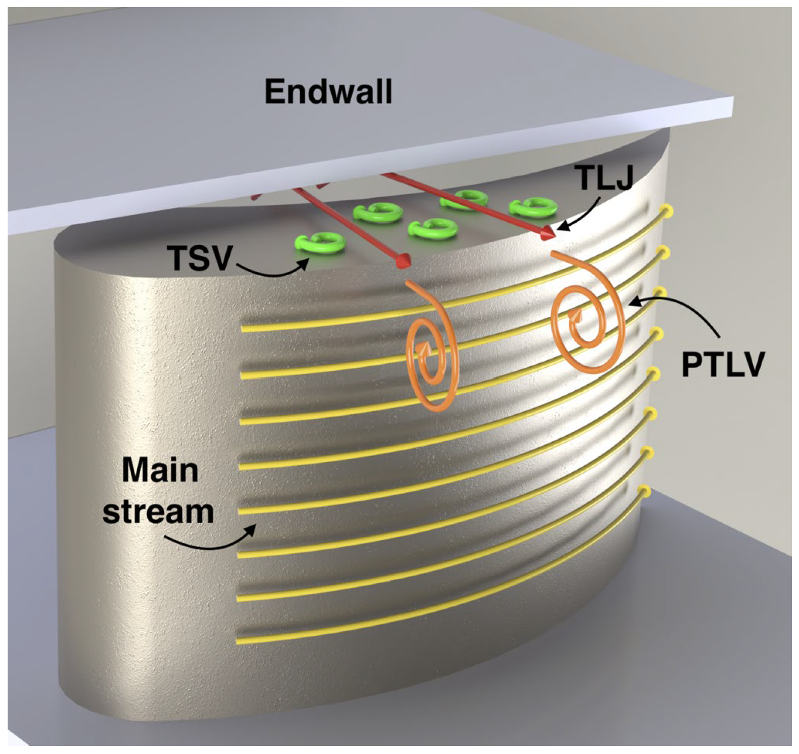
Tip leakage vortex is a complex three-dimensional flow phenomenon commonly found in turbomachinery. It arises from the gap between the blade tip and the casing. The pressure difference across the blade forces high-pressure fluid to leak through the tip clearance into the low-pressure side, generating a pronounced shear layer, a leakage jet, and the associated secondary vortex structures [3,4]. These features significantly modify the pressure and velocity gradients near the tip and give rise to a strong vortex system that affects the global aerodynamic performance. As illustrated in Figure 1, it shows the leakage flow driven by the pressure difference between the pressure and suction sides.
In engineering systems such as aero-engines, axial compressors, hydraulic pumps, and other turbomachinery systems, tip leakage flow increases energy loss near the endwall and reduces overall efficiency. The root cause of these problems lies in the formation and evolution of the tip leakage vortex (TLV). The tip leakage vortex results from the interaction between the leakage flow and the main flow. The characteristics of TLV formation depend on multiple interacting factors. Geometric parameters such as tip clearance, blade leading-edge radius, and blade loading strongly influence the position, strength, and morphology of the vortex [6,7,8,9,10]. It includes the primary tip leakage vortex and the secondary induced vortex [11,12].
More critically, tip leakage vortex may induce periodic pressure fluctuations that can trigger rotating stall or other unsteady phenomena [5,13], and it accelerates structural fatigue and seriously shortens the service life of equipment. Experimental and numerical studies have shown that unsteady phenomena in TLV primarily arise from three mechanisms:
  • A self-excited oscillation between the shear layer and the reattachment zone within the tip passage, which produces low-frequency pressure fluctuations [14];
  • Periodic interactions between the leakage vortex and the leading edge of the downstream blade [15];
  • Vortex breakdown (VB), in which the TLV core collapses under adverse pressure gradients and strong rotation [16,17].
Among these mechanisms, the first two have been widely explored, while vortex breakdown (VB) has recently emerged as a key factor in predicting the onset of instability in turbomachinery. Therefore, VB merits deeper exploration.
Vortex breakdown refers to the sudden collapse or loss of coherence of the tip leakage vortex due to inherent flow instabilities. The breakdown process is closely linked to the formation and evolution of the TLV [5,13]. Common triggers of TLV breakdown include strong adverse pressure gradients, structural interference, variations in inlet conditions, Coriolis effects, and even surface roughness [18]. Such triggers often act simultaneously, producing highly time-dependent and spatially asymmetric flow responses. Consequently, VB is not a localized structure but a complex dynamical system influenced by geometry, cavitation, and shear-layer instability. Its evolution is tightly coupled with vortex strength, Reynolds number, tip-clearance geometry, and endwall conditions. In hydraulic machines, cavitation interacts strongly with the TLV: the growth and collapse of vapor cavities modify the vortex core structure, while the vortex intensity feeds back into the cavitation dynamics [19,20]. In addition, the shear layer between the leakage flow and the main flow experiences Kelvin-Helmholtz (KH) instabilities, which introduce significant fluctuations in vortex strength, scale, and spectral behavior. These factors collectively shape the onset and development of vortex breakdown.
Therefore, understanding VB requires careful examination of the TLV structure and its coupling with cavitation.
In summary, the development of TLV-induced VB is governed by shear-layer instabilities, geometric modulation, cavitation effects, and fluid–structure interactions. To clarify these intertwined mechanisms, this review focuses on five key aspects:
  • Fundamental and Unsteady Characteristics of TLV;
  • Types, criteria, and prediction methods of VB;
  • Kelvin-Helmholtz instability and its influence on TLV evolution;
  • Cavitation interactions with KH and VB;
  • Geometric and boundary-condition modulation effects on TLV to improve system efficiency.
By establishing a coherent framework describing the instability pathway from initial shear-layer disturbances to the mechanism of VB, this paper aims to reveal methods for improving system efficiency by mitigating the unsteadiness associated with VB. By integrating theoretical, experimental, and numerical findings, this review provides physical insight and engineering guidance for flow-control strategies and stability optimization in rotating machinery.
Recent advances in numerical simulations and experimental diagnostics have substantially improved the understanding of tip leakage flow (TLF) and its associated instability mechanisms in turbomachinery. However, the current knowledge of TLF, Kelvin-Helmholtz (KH) instability, and vortex breakdown (VB) has been developed primarily through studies of aerodynamic turbomachinery, particularly compressors, whereas corresponding investigations in hydraulic turbomachinery remain relatively limited. Consequently, the applicability of compressor-based findings to hydraulic machinery should be carefully evaluated. To provide the necessary context for the remainder of this review, the following section first compares the similarities and differences between aerodynamic and hydraulic turbomachinery.

2. Similarities and Differences Between Aerodynamic and Hydraulic Turbomachinery

Although aerodynamic and hydraulic turbomachinery operate with different working fluids and under different operating conditions, they share many fundamental characteristics associated with tip-clearance flow. In both systems, the pressure difference across the blade tip drives the formation of tip leakage flow (TLF), which subsequently develops into a tip leakage vortex (TLV). Under typical operating conditions, tip-clearance flows in both systems occur at high Reynolds numbers, generally on the order of 105–106, and are therefore fully turbulent. As a result, the shear-layer development and the associated instability mechanisms exhibit strong physical similarities. Furthermore, both systems possess comparable tip-clearance jet structures and blade-tip geometries. The interaction between the TLV and the mainstream produces a strong shear layer that is susceptible to Kelvin-Helmholtz (KH) instability and, under appropriate conditions, may evolve into vortex breakdown (VB). These processes increase flow unsteadiness and contribute to additional aerodynamic or hydraulic losses. Consequently, the fundamental mechanisms governing TLF development, KH instability, and VB are largely independent of the working fluid and can be interpreted using a common physical framework. This similarity explains why compressor studies have provided valuable insight into the instability mechanisms observed in hydraulic turbomachinery.
Despite these similarities, several important differences arise from the distinct physical properties of air and water. Compressor flows are inherently compressible and often involve relatively high Mach numbers. In transonic compressors, shock-wave/boundary-layer interactions further complicate the tip leakage flow. In contrast, hydraulic turbomachinery operates under essentially incompressible conditions, where compressibility effects are negligible. Owing to the lower kinematic viscosity of water, thinner boundary layers and shear layers are typically formed, making the flow more sensitive to Reynolds-number variations and viscous effects. Hydraulic machines also generally operate at lower rotational speeds and employ fewer, wider blades, resulting in a relatively uniform inlet flow. By comparison, multistage compressors experience stronger wake interactions between blade rows, producing a more non-uniform inflow.
The most significant distinction between the two systems is the presence of cavitation. Unlike aerodynamic turbomachinery, where secondary flow phenomena are primarily governed by compressibility and shock-wave interactions, hydraulic turbomachinery exhibits a strong two-way coupling between cavitation and vortex dynamics. Cavitation preferentially develops within the low-pressure core of the TLV, modifying the local pressure, density, and vorticity fields. Oscillations of the cavity interface further enhance turbulence, alter vortex shedding frequency and trajectory, and influence the evolution of KH instability and VB. Conversely, the vortex trajectory, circulation strength, and breakdown process strongly affect cavitation inception, growth, and shedding. This mutual interaction makes the instability mechanisms in hydraulic turbomachinery substantially more complex than those in compressors.
Therefore, because aerodynamic and hydraulic turbomachinery share similar Reynolds-number ranges, tip-clearance jet structures, and blade-tip geometries, the current understanding of TLF formation, TLV evolution, shear-layer instability, KH instability, and the fundamental mechanisms of VB developed in compressor research provides an important foundation for studies of hydraulic machinery. However, conclusions involving cavitation dynamics, cavitation-induced instabilities, pressure fluctuations, and the coupling between cavitation and vortex evolution are specific to hydraulic turbomachinery and cannot be directly transferred from aerodynamic systems. These phenomena must be interpreted in the context of the physical properties of water and cavitation physics.
Accordingly, the following sections distinguish between instability mechanisms that are broadly applicable to both aerodynamic and hydraulic turbomachinery and those that are unique to hydraulic systems. Discussions of TLF formation, KH instability, and the fundamental mechanisms of vortex breakdown integrate findings from classical fluid mechanics, compressor research, and the available hydraulic-machinery literature. By comparison, discussions of cavitation dynamics and cavitation–TLV interactions are based primarily on studies of hydraulic turbomachinery. This organization allows the review to draw upon the mature understanding established in compressor research while appropriately accounting for the unique flow physics introduced by cavitation.

3. Fundamental Characteristics of Tip Leakage Flow

In turbomachinery, the clearance between blade tip and casing allows fluid from the pressure side to leak into the suction side. The process produces a complex three-dimensional spiral flow under the combined effects of centrifugal force, Coriolis force, blade curvature, and main flow interaction [21,22,23]. As the leakage develops, the flow evolves into a highly sheared layer with a concentrated vortex core structure [6,24]. Studies show that the tip leakage vortex forms through the roll-up of the tip leakage jet [25].
As shown in Figure 1, a typical TLV contains four characteristic regions. The first region is an inlet separation region. This region is located near the pressure side of the blade tip, and is marked by strong boundary layer separation and wall shear stress [6,26]. A distinct high-speed region also exists near the blade leading edge, with peak velocity reaching more than two times the mainstream value [27]. The second region is a clearance passage recirculation zone. In this zone, fluid flows along the casing within the tip gap, where local recirculation and vortex structures appear [28,29]. The third region is the jet core region. Here, the leakage jet produces a concentrated vortex core and the structure of this vortex often takes a horseshoe or helical form. The fourth and final region is a mixing and diffusion region. In this region intense momentum exchange occurs between the leakage vortex and main flow, with strong turbulent mixing [26,27,28]. The above-described regions are where the most dynamic and sensitive turbulent structures exist in the passage. These structures govern aerodynamic losses and flow instability.
The energy loss induced by TLV falls into three categories [26,30]: the first loss is the Separation Loss, caused by boundary layer separation near the inlet. The second loss is the Mixing Loss, caused by turbulent dissipation during shear mixing of the leakage jet and the main flow. The third loss is the Endwall Shear Loss, produced by endwall motion that redistributes flow [31,32]. Shear stress is strongest near the suction-side wall, which significantly increases loss. Velocity gradient near the endwall has been identified as the primary source of TLV loss [33]. Other studies attributed the loss mainly to endwall effects, blade profile, and incidence angle [32].
As the TLV moves closer to the leading edge, associated losses rise sharply, and system performance deteriorates rapidly [34]. TLV also induces flow deviation in the streamwise direction and angular momentum fluctuations, which generate secondary vortices such as hump vortices and counter-rotating structures.
Beyond its own complexity, TLV also shows strong coupling with the main flow. Radial expansion of TLV redistributes momentum in the passage. Interaction between TLV and the leading edge of downstream blades generates high-frequency pressure disturbances, which serve as precursors of rotating stall. TLV may couple with trailing-edge pulsations, leading to vortex splitting and blockage downstream [35]. The shear layer of TLF can disturb the boundary-layer stability of the main flow and expand separation zones.
In summary, TLV is driven by pressure difference across the blade tip. The three-dimensional structure interacts with mainstream, endwall, and boundary layers [36,37,38]. Energy loss originates from mixing, wall shear, and turbulence generation. The spatial scale is limited, yet the loss becomes significant under high-load conditions. More critically, TLV disturbs mainstream development, destabilizes boundary layers, and induces secondary vortices. The process links energy dissipation directly to mechanical disturbance. Thus, mixing, wall shear, and turbulence generation form the core drivers of TLV unsteady evolution.

4. Unsteady Characteristics of Tip Leakage Vortex

The unsteady features of TLV are the primary source of instability, performance fluctuation, and noise in turbomachinery. These unsteady behaviors appear as periodic or quasi-periodic pressure waves, vortex shedding, and disturbance propagation [35,39]. The dominant mechanisms include self-excited oscillations between the shear layer and reattachment zone in the gap [14], periodic interference between TLV and the leading edge of downstream blades, and structural vortex breakdown under adverse pressure gradients and rotation.
We first discuss the self-excited oscillation mechanism, which represents the first type of unsteady behavior [39]. In the tip gap, strong interaction exists between the inlet shear layer and reattached flow [29]. At certain Reynolds numbers and geometric conditions, this interaction produces spontaneous low-frequency disturbances. The disturbances show fixed frequencies and remain independent of external excitation. Recirculating structures inside the clearance passage may induce KH vortex structures within the shear layer. Their growth, collapse, and roll-up forms intermittently shed vortices. Particle image velocimetry (PIV) confirms these events as precursors of rotating stall [39]. As shown on the far Figure 1, the unsteady separation and shear interactions near the blade tip are the primary source of self-excited unsteadiness. To mitigate this effect, the authors gradually increased the blade thickness along the suction surface in the near-tip region, thereby forcing the mainstream to align more closely with the direction of the tip leakage jet. This design reduces the spanwise velocity gradient near the tip–suction surface corner [5].
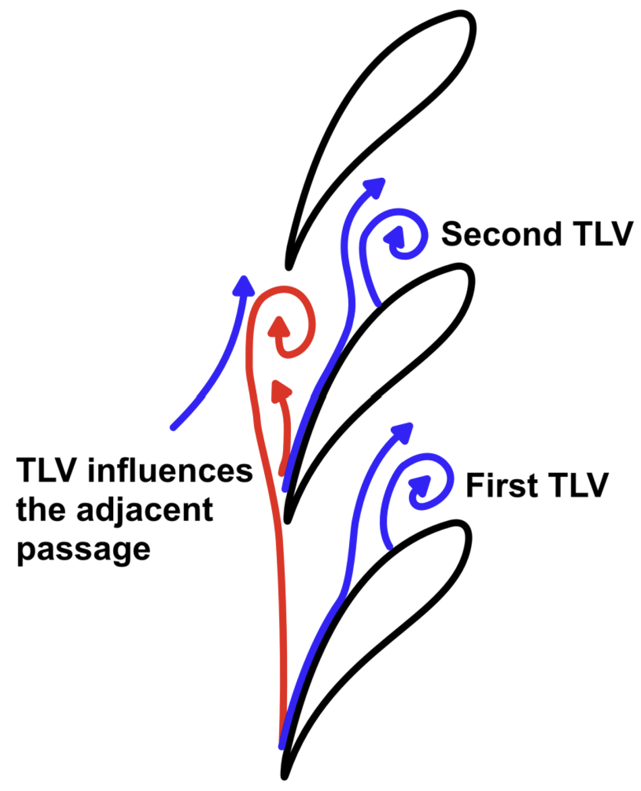
Next, we discuss the second major unsteady mechanism, the interaction between the TLV and the blade. As the TLV develops, it interacts periodically with the leading edge of downstream blades, as shown in Figure 2. In axial compressors, misalignment between the TLV wake and blade pressure surface produces large-amplitude periodic pressure fluctuations. These interactions can even generate shock–vortex coupling [40]. Some studies note that once stall occurs, the boundary between main flow and leakage flow moves to the leading edge of the main blade [41]. Other work highlights interaction between tip flow and stator wakes [35]. Both experiments and simulations show that these unsteady effects are strongest near the upper part of the passage. They are accompanied by distinct counter-rotating vortex wakes. As shown in Figure 1, the schematic illustrates the flow field associated with leading-edge separation induced by increasing tip clearance, together with the relationship between the stall flow coefficient and the tip clearance. As the clearance opens, the tip leakage flow suppresses the casing corner separation, while the tip leakage jet intensifies and becomes the dominant incidence mechanism.
The third unsteady mechanism corresponds to the vortex breakdown that arises from the evolution of the TLV. When TLV intensity increases and encounters adverse pressure gradients downstream, the vortex core can break down structurally. The process appears as helical collapse, axial stagnation, and reversal of the pressure core. These breakdown events disturb the pressure field severely and promote instability [42]. The unsteady behaviors manifest as broadband multi-modal disturbances that reduce compressor stability and complicate control.
In summary, accurate understanding and prediction of TLV unsteadiness are essential for improved turbomachinery efficiency and stability. Since self-excited oscillations and vortex–blade interactions are well studied, the following section of the review will focus on the mechanisms of vortex breakdown.

5. Vortex Breakdown in Tip Leakage Flow

Vortex breakdown (VB) in this study refers to the sudden collapse or instability of the core structure of the tip leakage vortex (TLV). It results from inherent flow instabilities. Vortex breakdown has been observed not only in slender wings [43,44] and diffusers [45] but also in the atmosphere [46,47,48,49,50,51]. The process alters the spatial structure and scale of the vortex, reduces flow stability, and generates intense noise [45]. It acts as a primary trigger for rotating stall, aero-excitation, and passage blockage [5,16,21,52].
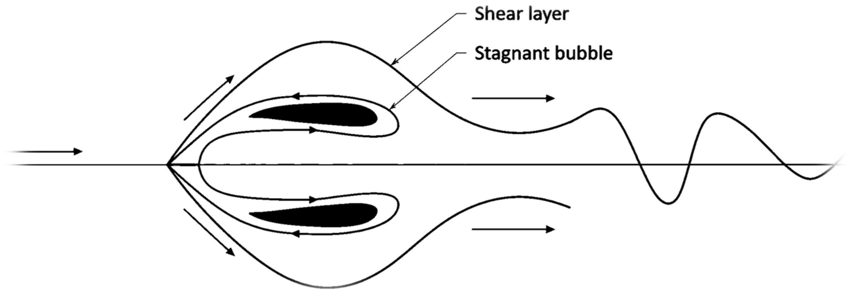
Typical signatures of TLV breakdown include rapid vorticity decay and collapse of the vortex core, along with increased core pressure, axial backflow, and stagnation points [16]. As shown in Figure 3, an interpretive schematic of the vortex breakdown structure is presented: The innermost region forms a bubble-like symmetric zone where stagnation occurs and the velocity is nearly zero. Surrounding this core is a nested annular structure rotating opposite to the incoming flow, and then this layer interacts with the outer flow to form a distinct shear layer. Notably, vortex breakdown also generates co-rotating and convective pressure pulsations [53]. In three-dimensional space, vortex breakdown appears as twisted or regenerated vortex bands. These bands may reorganize downstream into new coherent structures and induce multi-vortex interactions. As shown in Figure 3, the bubble formed after vortex breakdown develops into a spiral wake structure. In addition, vortex breakdown also exhibits hysteresis [54,55].
Vortex breakdown is usually categorized into six types: bubble-type, spiral-type, double-helix type, cone-type, jet-type, and wake-type, depending on the flow topology and instability characteristics. In hydraulic machinery, only spiral-type and bubble-type breakdowns are observed [53]. Common triggers of TLV breakdown include strong adverse pressure gradients, structural interference, changes in inlet conditions, Coriolis effects, and even surface roughness [18]. These factors often act together, producing strong time dependence and spatial asymmetry. The two most important factors are discussed further below.
Superimposed structural changes: Near diffuser exits or suction-side trailing edges, the TLV loses momentum and collapses [56]. Variations in inlet angle or outlet characteristics also influence breakdown. Operating fluctuations such as speed changes or inlet distortion cause TLV deflection, stretching, or displacement. Outlet condition changes also alter the structure of the breakdown process [57]. Compressibility can also affect vortex breakdown [58]. Coriolis force can accelerate or delay the process. Co-rotating rotation accelerates breakdown, while counter-rotation slows it [46,59,60]. The breakdown position and its subsequent evolution exhibit a clear temporal lag, indicating that the flow does not respond instantaneously to changes in the upstream conditions. Some studies attributed this to wave-like propagation of the broken vortex. Compared with inlet boundary layer thickness, the incidence angle plays a stronger role. Larger incidence angles move the breakdown location downstream [61].
The mutual interference between the tip leakage flow and other flow disturbances ultimately triggers vortex breakdown: The tip leakage vortex interacts with the suction-side boundary layer, wake vortices, main shear layers, or shocks. These interactions amplify nonlinear disturbances [62]. Coupling between leakage vortices and shocks produces spiral breakdown and unsteady flow phenomena [62]. In transonic axial compressors, the tip leakage vortex correlates with blade loading fluctuations and with shock motion. Some studies identify vortex–wave interference as the primary cause of TLV breakdown [63]. Vortex–wave interference also generates new vortex cores, which induce unsteady pressure fluctuations [64]. Gao et al. introduced vortex generators near the blade leading edge. They found that co-rotating vortices reduce TLV core velocity, weaken intensity, and delay or eliminate TLV breakdown. Counter-rotating vortices enhance breakdown due to stronger adverse pressure gradients induced by suction [65]. Many studies note that large incidence angles strongly promote breakdown [48,66].
In the breakdown process, TLV can interact with its own wake, upstream or downstream vortices, and the endwall. The interactions appear as vortex wrapping, core deflection, or coaxial merging, which bend or rupture the vortex. Interaction with the suction surface induces boundary layer separation and reduces total pressure rise of the rotor [16]. The tip leakage vortex penetrating the boundary layer produces secondary separation and mismatch with the main flow. Non-stationary vortex interactions may even suppress TLV breakdown [67]. Yang et al. studied the pressure field of an isolated subsonic compressor rotor blade. They reported that TLV breakdown generates a distorted backflow vortex (BFV). The BFV interacts with blade loading and causes local periodic variations. The variations produce low-frequency pressure fluctuations that correlate strongly with rotating instability [5]. These coupled dynamics show that vortex breakdown is not a local collapse but a global flow-field reconstruction.
The engineering implications of TLV breakdown are significant. First, it can induce extensive regions of localized stall in rotating machinery, severely degrading overall stability and reducing the achievable pressure ratio. TLV breakdown also produces asymmetric pressure pulsations, which may excite blade vibrations and lead to non-uniform blade loading. In addition, it amplifies disturbances in the blade wake, thereby diminishing the performance and stability of downstream stages. To mitigate the adverse effects associated with vortex breakdown, several engineering control strategies have been developed. One approach is to optimize the tip clearance or incorporate variable-clearance designs to delay the onset of breakdown. Forward-swept or curved blade geometries have also been employed to stabilize the TLV trajectory and suppress potential breakdown. Wall-based flow-control techniques—such as swirl injection, suction slots, or microjets—can be used to adjust the vorticity characteristics of the TLV and reduce its tendency to undergo breakdown [68]. Zhang et al. proposed adding an additional casing layer upstream of the blade inlet to induce a mild suction effect, thereby decreasing tip loading and weakening the interaction between the tip-leakage vortex and secondary vortices, which ultimately suppresses breakdown [68]. Other researchers have introduced an active feedback-control loop that regulates the amplitude of pressure fluctuations at targeted locations on a delta wing, enabling direct manipulation of the critical pressure conditions associated with breakdown [66]. Still others have explored real-time monitoring and early-warning systems based on vortex-breakdown signatures to enable adaptive control.
In summary, as shown in Table 1, the classification is based on the dominant mechanism explicitly identified in each study. It should be noted that vortex breakdown is often governed by multiple interacting mechanisms, and some effects (e.g., cavitation) are treated as coupled rather than primary triggers. When breakdown occurs, the associated efficiency penalty is commonly reported in the range of 2–8%, depending on operating conditions. TLV breakdown manifests as rapid loss of vortex strength, collapse or swelling of the vortex structure, and failure of axial transport. The process often occurs in the rear of the blade passage, especially near diffuser sections or stator inlets. Triggers include adverse pressure gradients, interference with secondary vortices or boundary layers, and resonance with external disturbances. Breakdown is not only a flow phenomenon but also a signal of system failure. It directly connects to performance loss, vibration growth, and reduced stall margin. Before breakdown, TLV is controlled by the shear interface between the leakage jet and the main flow. This structure is prone to Kelvin-Helmholtz instability [15]. Studies confirm that VB is closely linked to shear layer formation and induces stretching of the vortex core.

6. Shear Layer (Kelvin-Helmholtz Instability in Tip Leakage Flow)

A shear layer is a thin region of concentrated vorticity characterized by a large tangential velocity gradient between two adjacent flow streams. In tip leakage flow (TLF), the pressure difference across the blade tip drives a leakage jet that interacts with the mainstream, giving rise to a thin and highly unstable shear layer. The roll-up of this shear layer generates the high-vorticity tip leakage vortex (TLV), which governs the early-stage dynamics of the leakage flow. Because of the strong velocity gradient across the shear layer, it is highly susceptible to Kelvin-Helmholtz (KH) instability, leading to the formation of coherent vortical structures and the subsequent evolution of the TLV [73,74].
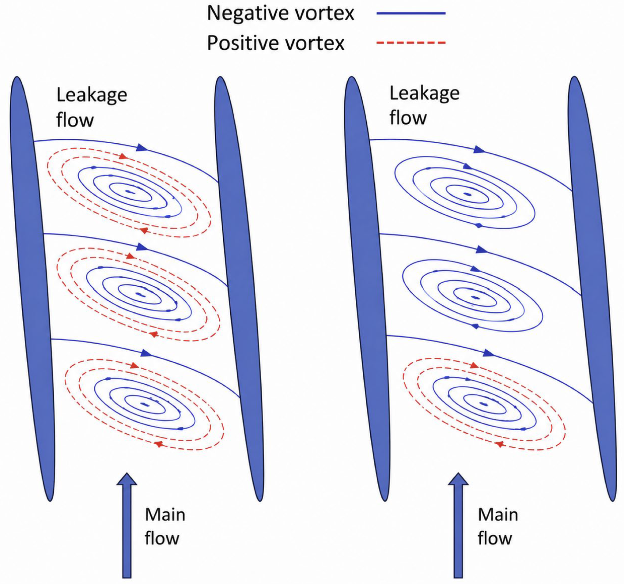
Kelvin-Helmholtz (KH) instability is a shear-driven instability. It develops at the interface of two fluid zones with similar density but different velocity. In tip leakage flow (TLF), KH instability arises along the velocity gradient between the leakage jet and the main flow. As shown in Figure 4, a schematic illustrates the formation of the shear layer generated by the mixing of the tip leakage vortex with the mainstream. The instability first appears as periodic disturbances. It then enters a nonlinear roll-up stage that forms a vortex sequence propagating along the TLV path. These structures disturb the vortex core trajectory and alter downstream evolution. Coupling between the shear layer and TLV produces rotating instabilities [75].
Necessary conditions for KH development include a sufficient velocity gradient across the shear layer, local disturbances that can grow rather than decay, and a shear interface close to a critical Reynolds number that promotes transition to turbulence. In TLV, the strong velocity difference between the leakage jet and the main flow satisfies these conditions, and the KH instability grows with downstream development of the shear layer [76].
Classical fluid-mechanics theory holds that the process originates from a stratified shear layer with an inflectional velocity profile. When the gradient Richardson number falls below the critical value somewhere in the flow, i.e., Ri < 1/4 (the Miles–Howard criterion), the shear layer becomes unstable to two-dimensional perturbations. Kelvin-Helmholtz (KH) instability does not form instantaneously; rather, it undergoes a complete nonlinear evolution comprising the amplification of the initial shear-layer perturbation, vortex roll-up, the formation of the KH billow, the development of three-dimensional secondary instabilities, and the eventual transition to turbulence.
Caulfield and Peltier were among the first to establish a complete framework for this evolution [77]. They showed that, once the KH billow forms, it does not transition directly to turbulence; instead, three-dimensional secondary instabilities first develop, generating streamwise vortices. These three-dimensional structures subsequently interact with one another and ultimately trigger the transition to turbulence and irreversible mixing, thereby providing a comprehensive theoretical basis for KH evolution. They characterized this evolution using the normalized total kinetic energy K/K0, the two-dimensional perturbation kinetic energy Kkh/K0, and the three-dimensional perturbation kinetic energy K3d/K0, examining how these quantities vary with Ri.
Building on this, Mashayek and Peltier investigated the three-dimensionalization of KH instability at high Reynolds number [78]. At relatively low Reynolds number (Re = 750), adjacent KH billows first undergo subharmonic pairing, which transfers energy from small to large scales and enhances turbulent mixing. As the Reynolds number increases (Re = 750 to 8000), however, three-dimensional secondary instabilities grow rapidly—including the shear-aligned convective instability (SCI), the secondary shear instability (SSI), and the stagnation-point instability (SPI). At sufficiently high Reynolds number, these three-dimensional instabilities can entirely suppress the vortex-pairing process, driving the flow from a two-dimensional to a three-dimensional state and accelerating the onset of turbulence. Because the growth of three-dimensional motion is accompanied by strong dissipation, the total kinetic energy drops sharply, indicating that three-dimensional secondary instability is one of the most critical controlling mechanisms in the KH transition to turbulence.
Liu and co-workers used direct numerical simulation (DNS) to examine the effect of a boundary on KH instability [79]. They introduced the characteristic KH time tkh, defined as the instant at which the kinetic energy of the primary KH mode reaches its maximum. When the shear layer is located far from the boundary (d = 10), tkh is approximately 120; when the shear layer is close to the boundary (d = 2.5), tkh increases to approximately 145, indicating that boundary confinement significantly delays the onset of KH instability. At the same time, the billow height is reduced, subharmonic pairing is suppressed, and the efficiency of turbulent mixing decreases.
For tip-leakage flows in turbomachinery, the governing factors and geometric characteristics are considerably more complex. Nonetheless, Bousquet and co-workers studied the formation and development of KH instability in a centrifugal compressor operating near stall [73]. They found that the strong shear layer produced by clearance-leakage flow first triggers KH instability, which subsequently develops into periodic vortex shedding while the compressor remains in stable operation and has not yet stalled. This suggests that, in this configuration, KH instability appears before large-scale flow breakdown and may serve as one of the earliest identifiable instability mechanisms preceding stall. On the basis of linear stability theory, the streamwise wavenumber of the most unstable KH mode satisfies
α = 0.4446 δ 0
where δ0 is the shear-layer half-thickness, and the corresponding wavelength satisfies
λ x = 2 π α
For this compressor case, the KH wavelength predicted by theory is 19.8 mm, in close agreement with the value of 17.66 mm obtained from the numerical simulation. This agreement further confirms that the KH instability originates from the initial shear layer and provides a reliable quantitative criterion for the roll-up process.
In summary, the evolution of KH instability follows a well-defined temporal progression that can be quantitatively described using parameters such as the characteristic KH time, the Reynolds number, the wavelength, the shear-layer thickness, and the normalized total, two-dimensional, and three-dimensional perturbation kinetic energies. The evidence from Bousquet and co-workers raises the possibility that KH instability may act as one of the earliest identifiable precursors to stall in tip-leakage flows. Confirming whether this holds more generally will require investigation across a wider range of machine geometries and operating conditions [29].
Furthermore, KH activity is sensitive to Reynolds number, velocity gradient, Coriolis forces, and wall proximity. Its interaction with TLV can amplify or suppress other unsteady behaviors. Most important, KH structures appear before vortex breakdown. They act as the earliest precursor for prediction models [29,80]. The evolution of KH structures is controlled by several factors, including:
  • Reynolds number (Re): Higher Re increases instability and vortex generation frequency;
  • Coriolis forces: In rotating frames, KH structures are compressed and deflected;
  • Wall proximity: Near-wall shear layers tend toward absolute instability, while free shear layers favor convective instability [73]. Near-wall conditions also delay transition, reduce KH amplitude, and prolong onset times [79];
  • Geometry and inlet disturbances: Tip radius, gap height, and inlet perturbations strongly affect KH onset and growth rate [81];
  • Cavitation: Cavity surface oscillations accelerate KH growth and promote hairpin vortices [82].
KH activity not only alters TLV trajectory but also modifies turbulence intensity in the shear layer and endwall interaction zones. This has direct implications for vortex control, loss management, and noise performance in compressors and pumps. A deeper understanding of KH mechanisms supports better turbulence models and more effective stall-control strategies.
KH activity precedes TLV breakdown, which makes it the primary early warning signal. The instability is also a key source of numerical uncertainty in CFD simulations. RANS models often fail to capture KH structures because strong eddy viscosity assumptions over dampen the shear layer [3]. Detached eddy simulation (DES) also struggles to resolve KH in mature flows [32,83]. LES and delayed DES (DDES) retain vortex chains and capture vortex formation, merging, and breakdown [80] but at high computational cost [84]. As shown in Figure 5, U-RANS is unable to adequately resolve the positive-vorticity structures associated with the tip leakage vortex, whereas DDES captures these vortical structures much more accurately. This demonstrates the superior capability of hybrid RANS–LES methods for predicting the unsteady evolution of TLV. DNS shows that KH instability can locally decouple TLV cores and form bent vortex wakes [15]. These structures either strengthen or weaken TLV dynamics and represent a core mechanism in three-dimensional unsteady high-fidelity simulations. In summary, KH instability is a shear-induced mechanism generated in the velocity gradient zone between the leakage jet and the main flow. The development of the instability is highly sensitive to Reynolds number, velocity gradient, Coriolis forces, and wall distance. Blade geometry and boundary-layer states further modulate its growth.
Furthermore, In hydraulic systems, cavitation is closely coupled with the evolution of the Kelvin-Helmholtz (KH) shear layer. Cavitation preferentially originates from streamwise vortices embedded within the turbulent shear layer, while KH instability initiates and governs cavity shedding. In turn, cavitation enhances vortex generation, modifies cross-flow velocity fluctuations and Reynolds stresses, and increases the boundary-layer thickness [83,85,86,87]. Furthermore, oscillations of the cavity interface promote the formation of complex vortical structures within the shear layer, reinforcing the bidirectional interaction between cavitation and KH instability [87]. These interface oscillations also amplify the growth of KH waves, facilitating the development of complex hairpin vortex structures [87]. In addition, the presence of non-condensable gases suppresses low-frequency irregular cavity shedding and alters boundary-layer separation, refs. [85,86] whereas cavitation promotes vortex formation and further thickens the boundary layer [83]. These findings highlight the strong feedback mechanism between cavitation and KH instability.
In addition, Following the formation of the tip leakage vortex (TLV), a strong shear layer develops between the leakage flow and the mainstream, making the flow susceptible to KH instability. Recent studies suggest that the resulting three-dimensional disturbances may promote vortex-core deformation and contribute to the onset of vortex breakdown under favorable flow conditions. However, the physical relationship between shear-layer instability, KH instability, and vortex breakdown has not yet been fully established. Additional theoretical, numerical, and experimental investigations are still needed to clarify the underlying mechanisms and to determine whether KH instability represents a direct precursor to vortex breakdown or simply accompanies its development [3,4,43,44,45,46,75,88,89].
In addition to shear layer influences, cavitation in hydraulic turbomachinery has a profound influence on the formation and evolution of tip leakage vortices, and it modifies both vortex breakdown and the shear layer, including KH instability.

7. Cavitation Coupling: Hysteresis Feedback and Flow Disturbance

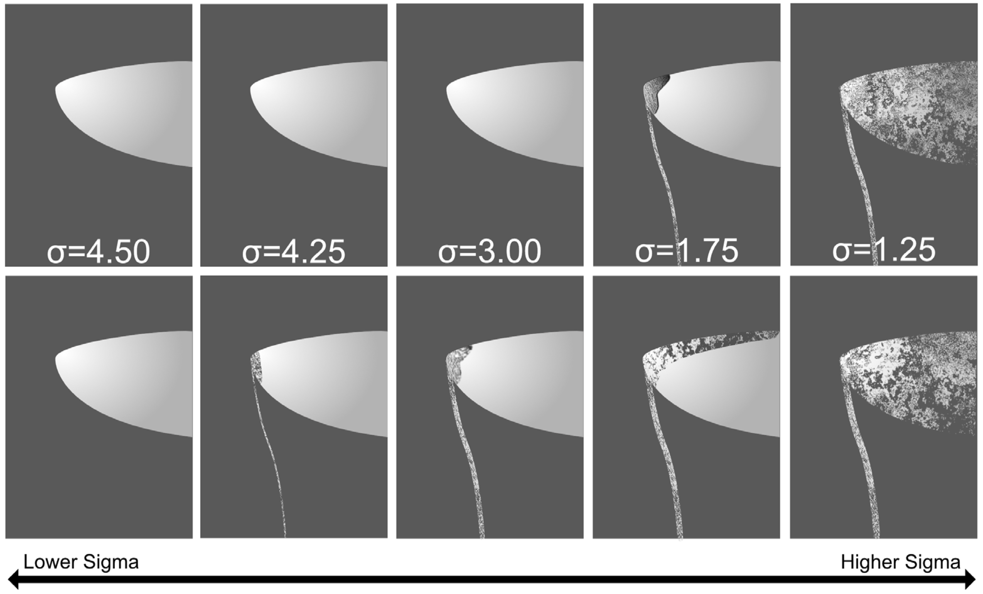
In hydraulic turbomachinery, cavitation bubble collapse generates extreme pressures, shock waves, rebound waves, and microjets in the surrounding liquid, and can cause fragmentation [90,91]. Under ideal symmetric collapse, pressures can exceed several hundred megapascals. Near solid boundaries, collapse becomes asymmetric and produces high-speed microjets that erode material [92,93]. Cavitation bubbles may also excite acoustic waves, shock waves, and even photon emission [93]. These shock waves propagate at speeds close to the speed of sound and are the primary cause of cavitation damage in hydraulic machines. The energy partition between rebound and shock waves depends on liquid pressure, fluid properties, and the partial pressure of non-condensable gas in the bubble [90]. The TLV core is a high-risk region for cavitation inception [94]. Once cavitation occurs, vapor bubbles modify the TLV density and pressure fields, induce trajectory deviations, and intensify local turbulence [19,20]. The growth–collapse cycle introduces hysteresis feedback that disrupts the quasi-periodic evolution of TLV [95]. Mohamed et al. reported that cavitation shows strong hysteresis during inception–collapse processes, as shown in Figure 6, it shows that the same cavitation number can lead to different cavitation behaviors due to variations in the experimental procedure. The effect depends on incidence angle, geometry, and free gas content. Some studies show that casing grooves can mitigate TLV cavitation effects [96]. The presence of the grooves introduces a more complex flow structure, producing a corner vortex at the groove inlet and a jet-like motion at the groove exit. Because some of the newly generated vortices follow the same trend as the production of the normal Reynolds-stress component, the grooves increase axial velocity fluctuations while reducing radial fluctuations. At the same time, the grooves absorb part of the momentum of the tip-leakage vortex, causing the originally strong, coherent vortex to break into several weaker vortices. This reduces the likelihood of unsteady flow development, particularly by weakening the primary tip-leakage vortex.
Cavitation is not only induced by vortex structures but also serves as a mechanism of vorticity generation [98]. Cavitation suppresses instabilities in the near-wake region and delays three-dimensional vortex breakdown [99]. Large vapor cloud collapses, distort and fragment U-shaped vortices at the interface [100]. Cavitation, therefore, alters vortex structures in both scale and evolution. Chunli et al. observed that the interaction between shed TLVs and those from adjacent blades produces local low-pressure cores that initiate cavitation [101]. Cavitating regions with smaller mixture viscosity (liquid volume fraction) promote strong vortex motion. Narrower vortex tubes are also more prone to cavitation [94].
Tip clearance height strongly affects the onset of gap cavitation. TLVs from adjacent blades may cross the tip and interact with the main passage flow to form low-pressure regions, which induce vortex ropes. Forward-swept blades reduce TLV cavitation, while backward-swept blades enhance it [102]. Some studies note that cavitation is most likely to occur at minimum clearance. Empirical equations have been proposed to predict cavitation inception, showing chordwise variation of cavitation sites [103]. Cavitation inception is most common in the TLV core and in chord sections where TLVs originate [104].
As TLVs propagate downstream, they bend and stretch due to interactions with trailing-edge vortices and adjacent TLVs. These interactions create new low-pressure cores [101] and sometimes generate special noise signatures [105]. Lower cavitation numbers increase the degree of total vapor content (TVC) variation, which produces stronger pressure fluctuations [106]. Vortex breakdown influences cavitation inception and collapse, forming elongated vapor cavities and distinct acoustic emissions. The noise is believed to result from bubble–vortex interactions [105].
Numerical studies show that cavitation modeling accuracy depends on turbulence and cavitation models. Simulations using the SST turbulence model with the Zwart cavitation model indicate that increasing the nucleation radius improves predictions of cavitation inception and collapse [107]. Experiments on cavitating vortex shedding from cylinders show that, with decreasing cavitation number, periodic cavitation transitions into transitional cavitation. Kármán vortices evolve from regular cavitation shedding to condensation shock waves, which increase shedding frequency by an order of magnitude [85]. Non-condensable gas suppresses low-frequency irregular–regular vortex shedding. Most vortex stretching, tilting, and vorticity production occur at the cavity tail. Gas content also affects boundary-layer separation [85,86].
Cloud cavitation studies show that condensation shock waves associated with phase change can appear at the cavity tail. These shocks persist longer than cavity collapse and control the periodic shedding cycle of cloud cavitation [108].
Researchers using high-speed photography and PIV observed that cavitation development in axial pumps is closely related to TLV strengthening [28,29]. The vortex stretching term dominates tip leakage cavitating flow evolution [109,110]. It delays vortex bending, enhances vortex expansion at the gas–liquid interface, disperses vortices, and shifts the TLV core trajectory away from the suction side. Cavitation also reduces vortex velocity and intensifies pressure fluctuations [111]. Cavitation decreases axial vortex velocity [112] and alters vorticity distribution in the vortex core, shifting the TLV trajectory closer to the suction side and endwall, which affects erosion risk [113]. Vortex strength decreases with cavitation number. Cavitation reduces leakage flow rate and increases pressure pulsations [109]. It also promotes vortex generation and increases boundary-layer thickness [114]. Gas content influences boundary-layer separation [85,86]. Zhu et al. found that cavitation changes vortex-core vorticity distribution, deflects TLV trajectory toward suction side and endwall, and aggravates local erosion. Cavitation alters vortex-core pulsation [115] and enhances turbulence [116]. It also modifies turbulence intensity in the tip region, affecting KH instability and TLV reattachment.
Observations show that cavitation expands with TLV entrainment at inception. Cavitation is then torn into filamentous structures by the main flow. Finally, cavities collapse in high-pressure zones and leave disturbed wakes. Cavitation modulates vortex shedding frequency and disrupts TLV unsteadiness [115]. Cavitation enlarges TLV scale and strength and prolongs its lifetime in the passage. The gas phase increases rigid vorticity magnitude, which modifies TLV shape [117]. Some studies suggest that a single bubble does not alter the form or position of VB [105]. Others report that lower cavitation numbers intensify vortex structures [118,119]. Moreover, thermodynamic effects can also influence cavitation and vortex dynamics, particularly in low-temperature conditions; however, these effects are not the primary focus of the present study [120].
Large-scale cavitation events may further distort the vortex core, thereby delaying or localizing the onset of three-dimensional vortex breakdown (VB). Simultaneously, filament-like vapor structures are generated and subsequently collapse in high-pressure regions, leaving behind disturbed wakes that modulate vortex shedding frequency and pressure fluctuations [19,103,117,121]. Conversely, the redistribution of vorticity and core expansion induced by vortex breakdown facilitate cavity elongation and produce distinct acoustic signatures. Although several studies have suggested that isolated cavitation bubbles do not significantly influence the onset of vortex breakdown, a reduction in cavitation bubble population has been shown to intensify vortex instability and flow unsteadiness.
In conclusion, cavitation weakens shear in low-pressure cores and introduces disturbances in collapse-induced wakes [122]. It modulates KH instability, vortex development, and breakdown dynamics. The result is a multiphysics coupled system governed by phase-change thresholds. At the system level, to improve the efficiency of pump turbines or other related turbomachinery, optimized geometric methods are among the best approaches.

8. Geometric and Boundary Optimization

Small geometric variations such as tip clearance, leading-edge radius, and blade loading exert strong influence on TLV dynamics [7,123]. Larger tip clearance leads to an increase in vortex strength and reduces stability. Sharper pressure-side angles promote early separation and TLV formation. Higher blade loading also raises the risk of vortex breakdown. Geometric parameters play an important role in TLV structure and stability, especially clearance height, leading-edge radius, and blade loading [6,8,9,10], as discussed below.
Tip Clearance: Increasing the tip clearance enhances the leakage energy and strengthens the tip leakage vortex (TLV), and it may also promote stall. At the same time, larger clearance can reduce blockage, since the leakage flow lowers the inlet incidence angle and alleviates separation. Thus, the optimal clearance represents a balance between aerodynamic losses and stability [39,124,125,126,127]. Some researchers have suggested that the optimum lies near 0.5% of the chord length, although the reported cases are limited and further study is needed. Complementary insights have been provided by hydrofoil experiments. For a relatively large clearance, the dominant vortical structures include the TLV, the tip separation vortex, and the induced vortex, whereas for a smaller clearance of 1.67%Ca, the reverse-flow vortex generated by the interaction between the spanwise flow and the hydrofoil sidewall becomes dominant. Hence, the observed reduction in hydrofoil losses with increasing clearance is primarily attributed to a shift in the dominant vortex structure toward the TLV [25].
Similar trends have been noted in turbomachinery applications. Studies of boiler circulation pumps in supercritical power plants showed that under deep stall conditions, a larger clearance (0.25%D, corresponding to 1.0 mm) suppressed forward-traveling vibrations and reduced average blade-edge deformation by 29.8% relative to a smaller clearance of 0.05%D. However, under optimal conditions, the larger clearance produced a 40% increase in deformation compared with the smaller gap [4]. Additional experimental observations reinforce these findings. Vortex-shedding tests with cylinders revealed that when the clearance ratio (defined as the ratio of clearance height to cylinder diameter) exceeds 0.35, the shedding becomes steady [7]. Other investigations indicated that the internal vortex structures within the tip clearance depend strongly on the ratio of clearance height to blade thickness [41]. Similarly, in backswept centrifugal compressors, increasing the clearance ratio from 0.06 to 0.21 was found to reduce the wall friction coefficient [128]. Collectively, these results highlight that the optimal tip clearance is not universal, but rather reflects a trade-off between loss and stability, shaped by vortex dynamics and operating conditions.
Leading Edge Radius: The tip leading-edge radius strongly influences both the size and shape of the separation bubble, as well as the transition mechanism of the tip flow. Increasing the leading-edge radius on the pressure side enlarges the inlet separation zone and alters the reattachment location. When the tip width w > 2.5τ (where τ is the tip clearance height), separation can reattach through turbulent mixing and pressure recovery within the gap. A rounded leading edge helps stabilize the shear layer, whereas a sharp edge promotes earlier separation. For blades subjected to prolonged operation and wear, the rounded leading edge often promotes unsteady behaviors such as vortex breakdown and oscillations [129]. The tip radius also modifies the balance of turbulence production mechanisms. When the radius is less than 10% of the tip width, turbulence is primarily generated by the breakdown of the shear layer in the pressure-side separation bubble. In contrast, when the radius exceeds 10% of the tip width, turbulence is mainly driven by the shedding associated with the mixing of the tip-surface boundary layer and the main channel flow [28].
Other factors also influence TLV behavior. Higher blade loading increases the likelihood of TLV breakdown. For example, when the loading level rises from 0.36 at the design point to 0.59, the stage total-to-static efficiency loss in a single-stage compressor with a 2.2% clearance increases from 2.3% to 3.4%, accompanied by stronger interactions with the suction-side boundary layer [130]. Experimental comparisons of 0 mm and 4 mm inlet boundary layers further demonstrated that a thicker boundary layer weakens the TLV intensity but enlarges the breakdown region, thereby worsening passage blockage [68].
Several flow-control strategies have also been proposed to alter the TLV dynamics. Perforations in the blade, as well as slots or axial grooves at the leading edge, have been shown to mitigate TLV while improving both efficiency and head rise [96,131,132,133,134]. More recently, novel wavy tip clearances have been investigated. Here, when the wave amplitude matches the clearance height, TLV suppression is most effective [135,136]. Similarly, introducing induced local jets or water injection into the tip region has also been reported to suppress tip leakage vortices [137,138].
In summary, Table 2 summarizes qualitative trends reported in the literature regarding TLV attenuation and cavitation mitigation. Small geometric changes such as clearance height, leading-edge radius, and blade loading strongly control TLV behavior. Larger clearance increases vortex strength but reduces system stability. Sharper pressure-side angles intensify separation and promote early TLV roll-up. Higher blade loading raises breakdown probability. These effects are often neglected in modeling but dominate real-machine behavior.

9. Conclusions

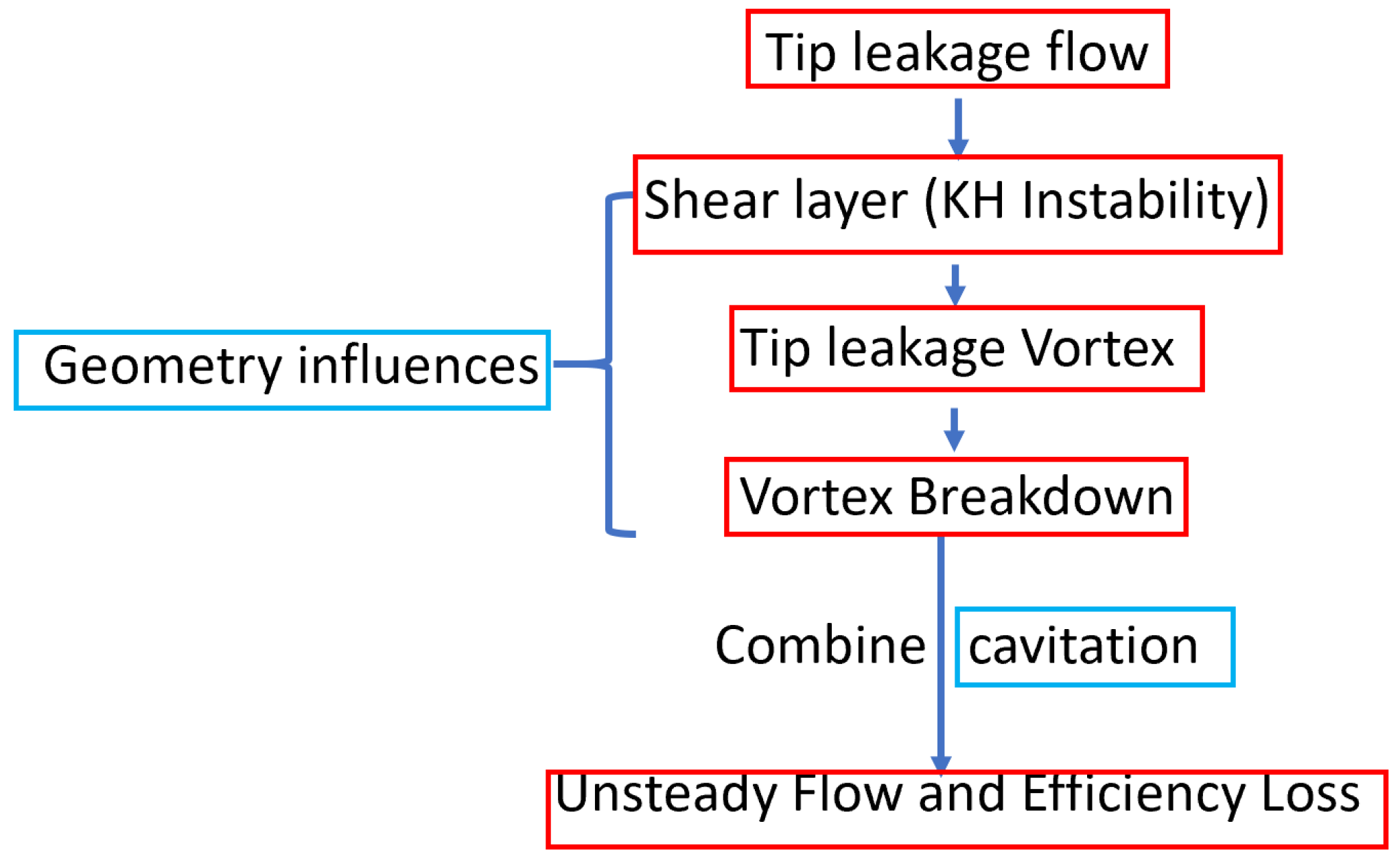
Tip leakage vortex is not only a local flow structure, but a system-level driver of efficiency loss, instability, and long-term reliability degradation in turbomachinery, as shown in Figure 7. Its dynamics arise from the interaction of shear layers, leakage jets, vortex cores, and boundary conditions. These interactions propagate beyond the blade tip region and influence overall hydraulic performance, pressure pulsation levels, cavitation inception, and structural loading. As a result, TLV directly affects system efficiency, operational stability, erosion rate, and service life.
The review highlights several key findings:
Vortex breakdown (VB): Breakdown manifests as spiral- or bubble-type collapse of the TLV core. It produces vorticity decay, pressure-core reversal, and blockage. VB amplifies pressure fluctuations, destabilizes blade loading, and reduces stall margin. It serves not only as a flow instability phenomenon but also as a macroscopic indicator of performance deterioration and reliability risk.
Kelvin-Helmholtz instability: KH instability develops along the shear layer between the leakage jet and the main flow. It produces vortex roll-up, entrainment, and rapid transition to turbulence. They are highly sensitive to Reynolds number, velocity gradients, Coriolis forces, wall proximity, and geometry. It implies that proper geometric optimization can delay instability growth and improve overall flow robustness. From a system perspective, controlling KH activity contributes directly to improved efficiency and extended operating range.
Cavitation effects: Cavitation couples tightly with TLV dynamics. Bubble growth and collapse modify pressure fields, amplify KH activity, and accelerate VB. Cavitation introduces hysteresis, increases turbulence, and promotes vortex deflection, stretching, and noise. Cavitating TLVs produce strong pressure pulsations and erosion risk, leading to severe performance degradation in hydraulic machinery. The coupled instability–cavitation mechanism forms a key pathway linking local vortex dynamics to system-level performance loss and durability reduction.
Geometric and boundary modulation: Clearance height, leading-edge radius, and blade loading strongly control TLV evolution. Through optimized geometric design, it is possible to weaken leakage intensity, suppress instability precursors, delay cavitation onset, and consequently enhance efficiency, stability, and service life. Larger clearances strengthen TLV but reduce stability. Higher blade loading increases breakdown probability. Geometry and boundary conditions, therefore function as instability control knobs.
The combined evidence shows that TLV is not a local flow phenomenon. Instead, it is a coupled, multiphysics system. KH instability acts as the earliest precursor and vortex breakdown represents the collapse of coherent structures. Geometry and endwalls modulate the dynamics and cavitation amplifies unsteadiness through phase-change feedback. Together, these mechanisms form a chain of instability that links system energy dissipation with performance loss and structural reliability.
Future progress toward high-efficiency and long-life turbomachinery requires an integrated system-level framework. It requires integrated experimental, numerical, and theoretical approaches. High-resolution measurements and high-fidelity simulations must be combined to resolve unsteady structures. Predictive models must include KH activity, VB, cavitation, and geometric effects in a unified framework. Active flow-control strategies should target early precursors such as KH waves and TLV cavitation to delay breakdown and extend the machine stall margin. Such approaches will enable simultaneous improvements in efficiency, operational stability, and lifecycle performance in pump-turbines and related turbomachinery systems.

Funding

This research received no external funding.

Data Availability Statement

No new data were created or analyzed in this study. Data sharing is not applicable to this article.

Conflicts of Interest

The authors declare no conflicts of interest.

References

  1. Lin, X.; Zhang, B.; Zhang, M.; Zhao, Y.; Lai, T.; Chen, L.; Xue, R. Influence of Internal Flow on the Performance of High-Speed Centrifugal Pumps with a Fully Sealed Structure. Appl. Sci. 2022, 12, 5263. [Google Scholar] [CrossRef]
  2. Zhou, W.; Su, H.; Liu, H.; Zhang, Y.; Qiu, N.; Gao, B. Leakage and Rotordynamic Performance of a Semi-Y Labyrinth Seal Structure for Centrifugal Pump Based on Multifrequency Whirl Method. J. Eng. Gas Turbines Power 2025, 147, 101022. [Google Scholar] [CrossRef]
  3. Lin, S.; Li, R.; Gao, L. Dynamic Characteristics of the Tip Clearance Flow Based on the Leakage Flow Model. In Proceedings of the ASME Turbo Expo 2024: Turbomachinery Technical Conference and Exposition, London, UK, 24–28 June 2024; Available online: https://asmedigitalcollection.asme.org/GT/proceedings-abstract/GT2024/88056/V12AT29A018/1204611 (accessed on 1 July 2026).
  4. Lv, H.; Guo, L.; Zhao, K.; Dai, J.; Li, Y.; Chen, S. Insight into blade tip vibration and deformation characteristics of boiler circulation pumps induced by tip leakage vortex under different tip clearances. Phys. Fluids 2024, 36, 045114. [Google Scholar] [CrossRef]
  5. Liu, Y.; Wang, Z.-N.; Tan, L.; Tucker, P.G.; Möller, F.M. Tip-leakage-flow excited unsteadiness and associated control. Phys. Fluids 2024, 36, 055156. [Google Scholar] [CrossRef]
  6. Storer, J.A.; Cumpsty, N.A. Tip Leakage Flow in Axial Compressors. J. Turbomach. 1991, 113, 252–259. [Google Scholar] [CrossRef]
  7. Bosch, G.; Kappler, M.; Rodi, W. Experiments on the flow past a square cylinder placed near a wall. Exp. Therm. Fluid Sci. 1996, 13, 292–305. [Google Scholar] [CrossRef]
  8. Li, P.; Zuo, Z.; Zhou, X.; Li, J.; Guo, W.; Chen, H. Characteristics of the axial compressor with different stator gaps in compressed air energy storage system. Proc. Inst. Mech. Eng. Part A J. Power Energy 2024, 238, 605–619. [Google Scholar] [CrossRef]
  9. Wisler, D.C. Loss Reduction in Axial-Flow Compressors Through Low-Speed Model Testing. J. Eng. Gas Turbines Power 1985, 107, 354–363. [Google Scholar] [CrossRef]
  10. Paduano, J.; Greitzer, E.; Epstein, A. Compression System Stability and Active Control. Annu. Rev. Fluid Mech. 2001, 33, 491–517. [Google Scholar] [CrossRef]
  11. Chen, Z.; Wu, Y.; An, G. Tip leakage flow, tip aerodynamic loading and rotating instability in a subsonic high-speed axial flow compressor rotor. Aerosp. Sci. Technol. 2021, 110, 106486. [Google Scholar] [CrossRef]
  12. Yang, F.; Wu, Y.; Chen, Z.; Spence, S.; Li, B. The unsteadiness of tip leakage vortex breakdown and its role in rotating instability. Phys. Fluids 2023, 35, 107108. [Google Scholar] [CrossRef]
  13. Coull, J.D.; Atkins, N.R. The Influence of Boundary Conditions on Tip Leakage Flow. J. Turbomach. 2015, 137, 061005. [Google Scholar] [CrossRef]
  14. Du, J.; Lin, F.; Zhang, H.; Chen, J. Numerical Investigation on the Self-Induced Unsteadiness in Tip Leakage Flow for a Transonic Fan Rotor. J. Turbomach. 2010, 132, 021017. [Google Scholar] [CrossRef]
  15. Fang, J.; Gao, Y.; Liu, Y.; Lu, L.; Yao, Y.; Le Ribault, C. Direct numerical simulation of a tip-leakage flow in a planar duct with a longitudinal slit. Phys. Fluids 2019, 31, 125108. [Google Scholar] [CrossRef]
  16. Furukawa, M.; Inoue, M.; Saiki, K.; Yamada, K. The role of tip leakage vortex breakdown in compressor rotor aerodynamics. J. Turbomach.-Trans. Asme 1999, 121, 469–480. [Google Scholar] [CrossRef]
  17. Saraswat, A.; Koley, S.S.; Joly, M.; Katz, J. Evolution of flow and turbulence over the entire tip region of an axial compressor rotor. Exp. Fluids 2025, 66, 87. [Google Scholar] [CrossRef]
  18. Godse, P.B.; Akolekar, H.D.; Pradeep, A.M. Surface roughness effects in a transonic axial flow compressor operating at near-stall conditions. Phys. Fluids 2024, 36, 105145. [Google Scholar] [CrossRef]
  19. Hou, J.; Liu, Y.; Tang, Y. A Lagrangian Analysis of Tip Leakage Vortex in a Low-Speed Axial Compressor Rotor. Symmetry 2024, 16, 344. [Google Scholar] [CrossRef]
  20. Ji, B.; Wang, X.; Bai, X.; Cheng, H.; Peng, X. Cavitation inception noise excited by a tip leakage vortex with various gap sizes: A Eulerian–Lagrangian investigation. Phys. Fluids 2023, 35, 122107. [Google Scholar] [CrossRef]
  21. Kumar, H.; Mistry, C.S. Understanding of tip clearance flow structure in high speed mixed flow compressor. Propuls. Power Res. 2023, 12, 356–379. [Google Scholar] [CrossRef]
  22. Stella, A.; Guj, G.; Di Felice, F.; Elefante, M. Experimental investigation of propeller wake evolution by means of LDV and flow visualizations. J. Ship Res. 2000, 44, 155–169. [Google Scholar] [CrossRef]
  23. Song, X.; Cao, P.; Zhang, J.; Lv, Z.; Li, G.; Liu, L. Dynamic Analysis of Tip Leakage Phenomena in Axial Flow Pumps Using a Square-Cavity Jet Model. Water 2024, 16, 676. [Google Scholar] [CrossRef]
  24. Wang, Z.; Ma, H.; Yang, Y.; Li, Z. Information transfer between tip leakage vortex and blade aerodynamic force of a compressor cascade. Aerosp. Sci. Technol. 2024, 153, 109400. [Google Scholar] [CrossRef]
  25. Shang, W.; Li, D.; Luo, K.; Fan, J.; Liu, J. Effects of tip clearance size on vortical structures and turbulence statistics in tip-leakage flows: A direct numerical simulation study. Phys. Fluids 2021, 33, 085127. [Google Scholar] [CrossRef]
  26. Taylor, J.V.; Dickens, A.M.J.; Simpson, H. Compressor Tip Leakage Mechanisms. J. Turbomach. 2024, 146, 051012. [Google Scholar] [CrossRef]
  27. Liao, Z.; Xue, Z.; Shen, J.; Zhou, Y.; Jin, Q.; Wu, X. Characteristics of tip leakage flow inside the tip clearance of an axial compressor. Phys. Fluids 2025, 37, 035127. [Google Scholar] [CrossRef]
  28. Maynard, J.M.; Wheeler, A.P.S.; Taylor, J.V.; Wells, R. Unsteady Structure of Compressor Tip Leakage Flows. J. Turbomach. 2023, 145, 051005. [Google Scholar] [CrossRef]
  29. Horwood, J.T.M.; Hualca, F.P.; Wilson, M.; Scobie, J.A.; Sangan, C.M.; Lock, G.D.; Dahlqvist, J.; Fridh, J. Flow Instabilities in Gas Turbine Chute Seals. J. Eng. Gas Turbines Power 2020, 142, 021019. [Google Scholar] [CrossRef]
  30. Denton, J.D. The 1993 IGTI Scholar Lecture: Loss Mechanisms in Turbomachines. J. Turbomach. 1993, 115, 621–656. [Google Scholar] [CrossRef]
  31. Ventosa-Molina, J.; Kreuseler, M.; Fröhlich, J. From linear to rotating compressor cascade: Assessment of data transferability. Phys. Fluids 2025, 37, 055107. [Google Scholar] [CrossRef]
  32. Lin, S.; Li, R.; Gao, L. Study on the Tip Leakage Loss Mechanism of a Compressor Cascade Using the Enhanced Delay Detached Eddy Simulation Method. Entropy 2024, 26, 295. [Google Scholar] [CrossRef] [PubMed]
  33. You, D.; Wang, M.; Moin, P.; Mittal, R. Large-eddy simulation analysis of mechanisms for viscous losses in a turbomachinery tip-clearance flow. J. Fluid Mech. 2007, 586, 177–204. [Google Scholar] [CrossRef]
  34. Montsarrat, C.; Boudet, J. Vortex Lattice Method Investigation of Tip-Leakage Flow. J. Turbomach. 2024, 146, 121009. [Google Scholar] [CrossRef]
  35. Lange, M.; Rolfes, M.; Mailach, R.; Schrapp, H. Periodic Unsteady Tip Clearance Vortex Development in a Low-Speed Axial Research Compressor at Different Tip Clearances. J. Turbomach. 2018, 140, 031005. [Google Scholar] [CrossRef]
  36. Yaras, M.I.; Sjolander, S.A.; Kind, R.J. Effects of Simulated Rotation on Tip Leakage in a Planar Cascade of Turbine Blades: Part II—Downstream Flow Field and Blade Loading. J. Turbomach. 1992, 114, 660–667. [Google Scholar] [CrossRef]
  37. Tallman, J.; Lakshminarayana, B. Numerical Simulation of Tip Leakage Flows in Axial Flow Turbines, with Emphasis on Flow Physics: Part II—Effect of Outer Casing Relative Motion. J. Turbomach. 2001, 123, 324–333. [Google Scholar]
  38. Ventosa-Molina, J.; Lange, M.; Mailach, R.; Fröhlich, J. Study of Relative Endwall Motion Effects in a Compressor Cascade Through Direct Numerical Simulations. J. Turbomach. 2021, 143, 011005. [Google Scholar] [CrossRef]
  39. Hewkin-Smith, M.; Pullan, G.; Grimshaw, S.D.; Greitzer, E.M.; Spakovszky, Z.S. The Role of Tip Leakage Flow in Spike-Type Rotating Stall Inception. J. Turbomach. 2019, 141, 061010. [Google Scholar] [CrossRef]
  40. Puterbaugh, S.L.; Brendel, M. Tip Clearance Flow-Shock Interaction in a Transonic Compressor Rotor. J. Propuls. Power 1997, 13, 24–30. [Google Scholar] [CrossRef] [PubMed]
  41. Zhao, H.; Wang, Z.; Ye, S.; Xi, G. Numerical investigations on tip leakage flow characteristics and vortex trajectory prediction model in centrifugal compressor. Proc. Inst. Mech. Eng. Part A J. Power Energy 2016, 230, 757–772. [Google Scholar] [CrossRef]
  42. Wu, Y.; An, G.; Wang, B. Numerical investigation into the underlying mechanism connecting the vortex breakdown to the flow unsteadiness in a transonic compressor rotor. Aerosp. Sci. Technol. 2019, 86, 106–118. [Google Scholar] [CrossRef]
  43. Di Felice, F. Experimental investigation of the propeller wake at different loading conditions by particle image velocimetry. J. Ship Res. 2004, 48, 168–190. [Google Scholar] [CrossRef]
  44. Wang, L.; Martin, J.E.; Felli, M.; Carrica, P.M. Experiments and CFD for the propeller wake of a generic submarine operating near the surface. Ocean Eng. 2020, 206, 107304. [Google Scholar] [CrossRef]
  45. Kc, A.; Lee, Y.H.; Thapa, B. CFD study on prediction of vortex shedding in draft tube of Francis turbine and vortex control techniques. Renew. Energy 2016, 86, 1406–1421. [Google Scholar] [CrossRef]
  46. Lugt, H.J.; Haussling, H.J. Vortex Breakdown in Fluids Rotating in a Fixed Cylindrical Vessel. Bull. Am. Phys. Soc. 1980, 25, 1087. [Google Scholar]
  47. Mayoral, S.; Massis, A. A Numerical Investigation of the Longitudinal Vortex Pair Structure in Underbody Diffuser Flows. J. Fluids Eng. 2025, 147, 071105. [Google Scholar] [CrossRef]
  48. Liu, J.; Luo, K.; Sun, H.; Huang, Y.; Liu, Z.; Xiao, Z. Dynamic response of vortex breakdown flows to a pitching double-delta wing. Aerosp. Sci. Technol. 2018, 72, 564–577. [Google Scholar] [CrossRef]
  49. Escudier, M.P. Observations of the Flow Produced in a Cylindrical Container by a Rotating Endwall. Exp. Fluids 1984, 2, 189–196. [Google Scholar] [CrossRef]
  50. Ismadi, M.-Z.P.; Meunier, P.; Fouras, A.; Hourigan, K. Experimental control of vortex breakdown by density effects. Phys. Fluids 2011, 23, 034104. [Google Scholar] [CrossRef]
  51. Lugt, H.J. Vortex Breakdown in Atmospheric Columnar Vortices. Bull. Am. Meteorol. Soc. 1989, 70, 1526–1537. [Google Scholar] [CrossRef]
  52. Schrapp, H.; Stark, U.; Saathoff, H. Unsteady behaviour of the tip clearance vortex in a rotor equivalent compressor cascade. Proc. Inst. Mech. Eng. Part A J. Power Energy 2009, 223, 635–643. [Google Scholar] [CrossRef]
  53. Khozaei, M.H.; Favrel, A.; Miyagawa, K. On the generation mechanisms of low-frequency synchronous pressure pulsations in a simplified draft-tube cone. Int. J. Heat Fluid Flow 2022, 93, 108912. [Google Scholar] [CrossRef]
  54. Billant, P.; Chomaz, J.-M.; Huerre, P. Experimental study of vortex breakdown in swirling jets. J. Fluid Mech. 1998, 376, 183–219. [Google Scholar] [CrossRef]
  55. Moise, P.; Mathew, J. Hysteresis and turbulent vortex breakdown in transitional swirling jets. J. Fluid Mech. 2021, 915, A94. [Google Scholar] [CrossRef]
  56. Visbal, M.R. Onset of Vortex Breakdown Above a Pitching Delta Wing. AIAA J. 1994, 32, 1568–1575. [Google Scholar] [CrossRef] [PubMed]
  57. Wu, Y.; Carlsson, C.; Szasz, R.; Peng, L.; Fuchs, L.; Bai, X. Effect of geometrical contraction on vortex breakdown of swirling turbulent flow in a model combustor. Fuel 2016, 170, 210–225. [Google Scholar] [CrossRef]
  58. Visbal, M.R.; Gordnier, R.E. Compressibility Effects on Vortex Breakdown Onset Above a 75-Degree Sweep Delta Wing. J. Aircr. 1995, 32, 936–942. [Google Scholar] [CrossRef]
  59. Koide, T.; Koyama, H.S. Vortex breakdown in a differentially rotating cylindrical container. J. Fluids Eng. 2005, 127, 358–366. [Google Scholar] [CrossRef]
  60. Dolai, A.; Boggavarapu, P.; Swaminathan, N.; Ravikrishna, R.V. Vortex breakdown modes in co/counter-swirling non-reacting and reacting flows. Phys. Fluids 2025, 37, 025212. [Google Scholar] [CrossRef]
  61. Gao, J.; Zheng, Q.; Xu, T.; Dong, P. Inlet conditions effect on tip leakage vortex breakdown in unshrouded axial turbines. Energy 2015, 91, 255–263. [Google Scholar] [CrossRef]
  62. Yamada, K.; Furukawa, M.; Nakano, T.; Inoue, M.; Funazaki, K. Unsteady Three-Dimensional Flow Phenomena Due to Breakdown of Tip Leakage Vortex in a Transonic Axial Compressor Rotor. In Proceedings of the ASME Turbo Expo 2004: Power for Land, Sea, and Air; ASME: New York, NY, USA, 2004; pp. 515–526. [Google Scholar]
  63. An, G.; Kang, J.; Zou, Y.; Zhang, L.; Lang, J.; Yuan, W.; Zhang, Q. Investigation of the unsteady flow in a transonic axial compressor adopted in the compressed air energy storage system. J. Energy Storage 2023, 63, 106928. [Google Scholar] [CrossRef]
  64. Peng, S.; Zhang, X.; Wang, W.; Zhang, H.; Li, X. Numerical Simulation on Unsteady Flow Mechanism of a 1.5-Stage Axial Transonic Compressor. J. Therm. Sci. 2024, 33, 1851–1866. [Google Scholar] [CrossRef]
  65. Gao, X.; Cao, Z.; Liu, B. RANS investigation of incoming vortex on the tip leakage vortex breakdown in an aspirated compressor cascade. Int. J. Heat Fluid Flow 2025, 114, 109796. [Google Scholar] [CrossRef]
  66. Gursul, I.; Srinivas, S.; Batta, G. Active Control of Vortex Breakdown Over a Delta Wing. AIAA J. 1995, 33, 1743–1745. [Google Scholar] [CrossRef] [PubMed]
  67. Zhou, K.; Zhou, C. Unsteady effects of vortex interaction on tip leakage vortex breakdown and its loss mechanism. Aerosp. Sci. Technol. 2018, 82–83, 363–371. [Google Scholar] [CrossRef]
  68. Zhang, B.; Liu, B.; Mao, X.; Zhang, R. Combined control of variant clearance and casing aspiration on tip flow field and instability of a transonic compressor. Aerosp. Sci. Technol. 2022, 127, 107702. [Google Scholar] [CrossRef]
  69. Wang, B.; Wu, Y.; Yang, F.; Spence, S. Intermittent breakdown of the tip leakage vortex and the resultant flow unsteadiness in the tip-region of a subsonic compressor cascade. Aerosp. Sci. Technol. 2021, 113, 106679. [Google Scholar] [CrossRef]
  70. Sarpkaya, T. On Stationary and Travelling Vortex Breakdowns. J. Fluid Mech. 1971, 45, 545–559. [Google Scholar] [CrossRef]
  71. Moise, P.; Mathew, J. Bubble and conical forms of vortex breakdown in swirling jets. J. Fluid Mech. 2019, 873, 322–357. [Google Scholar] [CrossRef]
  72. Hou, J.; Liu, Y. Evolution of unsteady vortex structures in the tip region of an axial compressor rotor. Phys. Fluids 2023, 35, 045107. [Google Scholar] [CrossRef]
  73. Bousquet, Y.; Binder, N.; Dufour, G.; Carbonneau, X.; Trebinjac, I.; Roumeas, M. Numerical Investigation of Kelvin-Helmholtz Instability in a Centrifugal Compressor Operating Near Stall. J. Turbomach. 2016, 138, 071007. [Google Scholar] [CrossRef]
  74. Inoue, M.; Furukawa, M.; Saiki, K.; Yamada, K. Physical Explanations of Tip Leakage Flow Field in an Axial Compressor Rotor. In Proceedings of ASME Turbo Expo; Paper No. 98-GT-091; ASME: New York, NY, USA, 1998. [Google Scholar]
  75. Deng, H.; Zhang, S.; Xia, K.; Qiang, X.; Zhu, M.; Teng, J. Partial rotating instability in a boundary layer ingesting fan. Chin. J. Aeronaut. 2025, 38, 103343. [Google Scholar] [CrossRef]
  76. Cao, T.; Kanzaka, T.; Xu, L.; Brandvik, T. Tip Leakage Flow Instability in a Centrifugal Compressor. J. Eng. Gas Turbines Power 2021, 143, 041012. [Google Scholar] [CrossRef]
  77. Caulfield, C.P.; Peltier, W.R. The anatomy of the mixing transition in homogeneous and stratified free shear layers. J. Fluid Mech. 2000, 413, 1–47. [Google Scholar] [CrossRef]
  78. Mashayek, A.; Peltier, W.R. Three-dimensionalization of the stratified mixing layer at high Reynolds number. Phys. Fluids 2011, 23, 111701. [Google Scholar] [CrossRef]
  79. Liu, C.-L.; Kaminski, A.K.; Smyth, W.D. The effects of boundary proximity on Kelvin-Helmholtz instability and turbulence. J. Fluid Mech. 2023, 966, A2. [Google Scholar] [CrossRef]
  80. Liu, Y.; Zhong, L.; Lu, L.-P. Comparison of DDES and URANS for Unsteady Tip Leakage Flow in an Axial Compressor Rotor. J. Fluids Eng. 2019, 141, 121405. [Google Scholar] [CrossRef]
  81. Liu, C.-L.; Kaminski, A.K.; Smyth, W.D. The butterfly effect and the transition to turbulence in a stratified shear layer. J. Fluid Mech. 2022, 953, A43. [Google Scholar] [CrossRef]
  82. Ye, Q.; Wang, Y.; Shao, X. Dynamics of cavitating tip vortex. J. Fluid Mech. 2023, 967, A30. [Google Scholar] [CrossRef]
  83. Lin, S.; Li, R.; Gao, L.; Ge, N. Accuracy Investigations of Dynamic Characteristic Predictions of Tip Leakage Flow Using Detached Eddy Simulation. Aerospace 2023, 11, 29. [Google Scholar] [CrossRef]
  84. He, X.; Zhao, F.; Vahdati, M. Detached Eddy Simulation: Recent Development and Application to Compressor Tip Leakage Flow. J. Turbomach. 2022, 144, 011009. [Google Scholar] [CrossRef]
  85. Brandao, F.L.; Bhatt, M.; Mahesh, K. Numerical study of cavitation regimes in flow over a circular cylinder. J. Fluid Mech. 2019, 885, A19. [Google Scholar] [CrossRef]
  86. Briançon-Marjollet, L.; Franc, J.P.; Michel, J.M. Transient bubbles interacting with an attached cavity and the boundary layer. J. Fluid Mech. 2006, 218, 355–376. [Google Scholar] [CrossRef]
  87. O’Hern, T.J. An experimental investigation of turbulent shear flow cavitation. J. Fluid Mech. 2006, 215, 365–391. [Google Scholar] [CrossRef]
  88. Gursul, I.; Gordnier, R.; Visbal, M. Unsteady aerodynamics of nonslender delta wings. Prog. Aerosp. Sci. 2005, 41, 515–557. [Google Scholar] [CrossRef]
  89. Spall, R.E.; Gatski, T.B.; Grosch, C.E. A criterion for vortex breakdown. Phys. Fluids 1987, 30, 3434–3440. [Google Scholar] [CrossRef]
  90. Tinguely, M.; Obreschkow, D.; Kobel, P.; Dorsaz, N.; de Bosset, A.; Farhat, M. Energy partition at the collapse of spherical cavitation bubbles. Phys. Rev. E 2012, 86, 046315. [Google Scholar] [CrossRef] [PubMed]
  91. Brennen, C.E. Fission of collapsing cavitation bubbles. J. Fluid Mech. 2002, 472, 153–166. [Google Scholar] [CrossRef]
  92. Lauterborn, W.; Bolle, H. Experimental investigations of cavitation-bubble collapse in the neighbourhood of a solid boundary. J. Fluid Mech. 2006, 72, 391–399. [Google Scholar] [CrossRef]
  93. Brennen, C.E. Cavitation in medicine. Interface Focus 2015, 5, 20150022. [Google Scholar] [CrossRef] [PubMed]
  94. Yu, C.; Wang, Y.; Huang, C.; Wu, X.; Du, T. Large Eddy Simulation of Unsteady Cavitating Flow Around a Highly Skewed Propeller in Nonuniform Wake. J. Fluids Eng. 2017, 139, 041302. [Google Scholar] [CrossRef]
  95. Li, L.; Huo, Y.; Wang, Z.; Li, X.; Zhu, Z. Large eddy simulation of tip-leakage cavitating flow using a multiscale cavitation model and investigation on model parameters. Phys. Fluids 2021, 33, 092104. [Google Scholar] [CrossRef]
  96. Zhang, T.; Gao, X.; Li, H.; Hao, X. Numerical study of effect of the casing slot on the tip leakage vortex and vortex cavitation of a fuel pump. Int. J. Turbo Jet-Engines 2025, 42, 533–543. [Google Scholar] [CrossRef]
  97. Amini, A.; Reclari, M.; Sano, T.; Iino, M.; Dreyer, M.; Farhat, M. On the physical mechanism of tip vortex cavitation hysteresis. Exp. Fluids 2019, 60, 118. [Google Scholar] [CrossRef]
  98. Arndt, R.E. Cavitation in Vortical Flows. Annu. Rev. Fluid Mech. 2002, 34, 143–175. [Google Scholar] [CrossRef]
  99. Pendar, M.-R.; Roohi, E. Cavitation characteristics around a sphere: An LES investigation. Int. J. Multiph. Flow 2018, 98, 1–23. [Google Scholar] [CrossRef]
  100. Wang, C.; Zhang, Y.; Yuan, Z.; Liu, Z. Evaluating of the effect of the cavitation-vortex interaction on the energy conversion in a two-stage LNG cryogenic submerged pump. Proc. Inst. Mech. Eng. Part A J. Power Energy 2023, 237, 98–114. [Google Scholar] [CrossRef]
  101. Hah, C.; Lee, Y.-T. Unsteady Pressure Field Due to Interactions Among Tip Leakage Vortex, Trailing Edge Vortex, and Vortex Shedding in a Ducted Propeller. In Proceedings of the ASME Turbo Expo 2007: Power for Land, Sea, and Air; ASME: New York, NY, USA, 2007; pp. 1639–1646. [Google Scholar]
  102. Laborde, R.; Chantrel, P.; Mory, M. Tip Clearance and Tip Vortex Cavitation in an Axial Flow Pump. J. Fluids Eng. 1997, 119, 680–685. [Google Scholar] [CrossRef]
  103. Farrell, K.J.; Billet, M.L. A Correlation of Leakage Vortex Cavitation in Axial-Flow Pumps. J. Fluids Eng. 1994, 116, 551–557. [Google Scholar] [CrossRef]
  104. Liu, Y.; Tan, L.; Wang, B. A Review of Tip Clearance in Propeller, Pump and Turbine. Energies 2018, 11, 2202. [Google Scholar] [CrossRef]
  105. Ganesh, H.; Schot, J.; Ceccio, S.L. Stationary cavitation bubbles forming on a delta wing vortex. Phys. Fluids 2014, 26, 127102. [Google Scholar] [CrossRef]
  106. Lak, S.; Jaiman, R. A numerical study on the oscillatory dynamics of tip vortex cavitation. J. Fluid Mech. 2024, 998, A13. [Google Scholar] [CrossRef]
  107. Avanzi, F.; Baù, A.; De Vanna, F.; Benini, E. Numerical Assessment of a Two-Phase Model for Propulsive Pump Performance Prediction. Energies 2023, 16, 6592. [Google Scholar] [CrossRef]
  108. Budich, B.; Schmidt, S.J.; Adams, N.A. Numerical simulation and analysis of condensation shocks in cavitating flow. J. Fluid Mech. 2018, 838, 759–813. [Google Scholar] [CrossRef]
  109. Cheng, H.Y.; Bai, X.R.; Long, X.P.; Ji, B.; Peng, X.X.; Farhat, M. Large eddy simulation of the tip-leakage cavitating flow with an insight on how cavitation influences vorticity and turbulence. Appl. Math. Model. 2020, 77, 788–809. [Google Scholar] [CrossRef]
  110. Chen, T.; Mu, Z.; Chen, J.; Tan, S.; Fan, Y. Numerical investigations on the mechanisms of the tip leakage vortex cavitation development in a cryogenic inducer with large eddy simulation. Phys. Fluids 2023, 35, 073328. [Google Scholar] [CrossRef]
  111. Zhang, H.; Wang, J.; Zhang, D.; Shi, W.; Zang, J. Numerical Analysis of the Effect of Cavitation on the Tip Leakage Vortex in an Axial-Flow Pump. J. Mar. Sci. Eng. 2021, 9, 775. [Google Scholar] [CrossRef]
  112. Dreyer, M. Mind the Gap: Tip Leakage Vortex Dynamics and Cavitation in Axial Turbines; École Polytechnique Fédérale de Lausanne: Lausanne, Switzerland, 2015. [Google Scholar]
  113. Decaix, J.; Dreyer, M.; Balarac, G.; Farhat, M.; Münch, C. RANS computations of a confined cavitating tip-leakage vortex. Eur. J. Mech.-B/Fluids 2018, 67, 198–210. [Google Scholar] [CrossRef]
  114. Ji, B.; Luo, X.; Arndt, R.E.; Wu, Y. Numerical simulation of three dimensional cavitation shedding dynamics with special emphasis on cavitation–vortex interaction. Ocean Eng. 2014, 87, 64–77. [Google Scholar] [CrossRef]
  115. Long, Y.; Zhou, Z.; Li, N.; Zhang, M.; An, C.; Chen, Y.; Zhu, R. Experimental and Numerical Investigation of Tip Leakage Vortex Cavitation in Water-jet Pump. J. Appl. Fluid Mech. 2024, 17, 1191–1203. [Google Scholar] [CrossRef]
  116. Xu, S.; Xiong, Y.; Tang, F.; Li, G.; Long, X.; Ji, B.; Huang, R. The investigation on the flow characteristics during the continuous development of the tip leakage vortex cavitation in an axial pump-jet propulsion. Phys. Fluids 2024, 36, 055152. [Google Scholar] [CrossRef]
  117. Shi, G.; Sun, G.; Wang, Q.; Quan, H.; Huang, Z.; Wen, H.; Hao, Z. Dynamic characteristics of the tip leakage vortex in an oil–gas multiphase pump based on vorticity decomposition theory. Energy Sci. Eng. 2024, 12, 2918–2943. [Google Scholar] [CrossRef]
  118. Jia, X.; Zhong, S.; Miao, H.; Ren, Q.; Liu, G.; Li, X.; Lin, Z.; Zhang, S.; Zhu, Z. Research on internal cavitation flow in axial flow pump focusing on the energy dissipation under varied operating conditions. Phys. Fluids 2025, 37, 035188. [Google Scholar] [CrossRef]
  119. Koncoski, J.J.; Kunz, R.F.; Nickels, A.S.; Devilbiss, D.W.; Harris, J.R. Experimental characterization of the flowfield and cavitation physics of a tip-loaded hydrofoil. Phys. Fluids 2023, 35, 053336. [Google Scholar] [CrossRef]
  120. Ge, M.; Sun, C.; Zhang, G.; Coutier-Delgosha, O.; Fan, D. Combined suppression effects on hydrodynamic cavitation performance in Venturi-type reactor for process intensification. Ultrason. Sonochem. 2022, 86, 106035. [Google Scholar] [CrossRef] [PubMed]
  121. Ausoni, P.; Farhat, M.; Escaler, X.; Egusquiza, E.; Avellan, F. Cavitation Influence on von Kármán Vortex Shedding and Induced Hydrofoil Vibrations. J. Fluids Eng. 2007, 129, 966–973. [Google Scholar] [CrossRef]
  122. Li, W.; Liu, M.; Ji, L.; Li, S.; Song, R.; Wang, C.; Cao, W.; Agarwal, R.K. Study on the trajectory of tip leakage vortex and energy characteristics of mixed-flow pump under cavitation conditions. Ocean Eng. 2023, 267, 113225. [Google Scholar] [CrossRef]
  123. Rafiee, S.E.; Grönman, A.; Uusitalo, A.; Turunen-Saaresti, T. Comprehensive study on the design and analysis of supercritical carbon dioxide (sCO2) radial outflow turbines (ROTs), focusing on tip clearance effects, loss correlations, and performance evaluation. Appl. Therm. Eng. 2025, 272, 126399. [Google Scholar] [CrossRef]
  124. Adamczyk, J.J.; Celestina, M.L.; Greitzer, E.M. The Role of Tip Clearance in High-Speed Fan Stall. J. Turbomach. 1993, 115, 28–38. [Google Scholar] [CrossRef]
  125. Cumpsty, N.A. Discussion: “The Role of Tip Clearance in High-Speed Fan Stall” (Adamczyk, J.J., Celestina, M.L., and Greitzer, E.M., 1993, ASME J. Turbomach., 115, pp. 28–38). J. Turbomach. 1993, 115, 39. [Google Scholar] [CrossRef]
  126. Yoon, Y.S.; Song, S.J.; Shin, H.-W. Influence of Flow Coefficient, Stagger Angle, and Tip Clearance on Tip Vortex in Axial Compressors. J. Fluids Eng. 2006, 128, 1274–1280. [Google Scholar] [CrossRef]
  127. Turunen-Saaresti, T.; Jaatinen, A. Influence of the Different Design Parameters to the Centrifugal Compressor Tip Clearance Loss. J. Turbomach. 2013, 135, 011017. [Google Scholar] [CrossRef]
  128. Hong, S.-S.; Abhari, R.S. Effect of tip clearance on impeller discharge flow and vaneless diffuser performance of a centrifugal compressor. Proc. Inst. Mech. Eng. Part A J. Power Energy 2012, 226, 963–974. [Google Scholar] [CrossRef]
  129. Stein, T.; Leitner, M.W.; Staudacher, S. Effect of Leading Edge Erosion on the Tip Leakage Flow in a Compressor Cascade. J. Turbomach. 2025, 147, 081015. [Google Scholar] [CrossRef]
  130. Yu, X.; Hou, J.; An, G.; Liu, B. Experimental study on the blade tip clearance sensitive effect in compressors with different loading levels. Phys. Fluids 2024, 36, 065140. [Google Scholar] [CrossRef]
  131. Gang, Y.; Zhou, Z.; Li, J.; Peng, L.; Liu, D.; Liu, X.; Pang, J. Analysis of hydrofoil tip leakage vortex dynamic characteristics. Adv. Mech. Eng. 2024, 16, 1–10. [Google Scholar] [CrossRef]
  132. Wu, H.; Zhang, D.; Shen, X.; Ni, C.; Yang, G. Study on the Suppression of Tip Leakage Vortex in Axial Flow Pumps Based on Circumferential Grooving in the Rotor Chamber. J. Mar. Sci. Eng. 2025, 13, 972. [Google Scholar] [CrossRef]
  133. Xiao, Y.; Yang, G.; Lu, H.; Yuan, Y. Blade retrofit design to reduce the noise of an axial flow fan by mitigating the tip leakage vortex. Int. J. Aeroacoustics 2024, 23, 441–467. [Google Scholar] [CrossRef]
  134. Eckel, J.; Reisinger, L.; von Jeinsen, P.; Gümmer, V. Numerical Investigation of the Interaction of a Circumferential Groove Casing Treatment and Near-Tip Modifications for a Highly Loaded Low-Speed Rotor Under the Influence of Double Leakage. J. Turbomach. 2024, 146, 071001. [Google Scholar] [CrossRef]
  135. Gu, F.; Shi, L.; Shen, X.; Zhang, G.; Geng, L.; Zhang, D.; van Esch, B. A novel flow control method suppressing tip leakage vortex of a hydrofoil applied for ducted devices. Ocean Eng. 2024, 311, 118920. [Google Scholar] [CrossRef]
  136. Wang, L.; Feng, J.; Lu, J.; Zhu, G.; Wang, W. Novel bionic wave-shaped tip clearance toward improving hydrofoil energy performance and suppressing tip leakage vortex. Energy 2024, 290, 130261. [Google Scholar] [CrossRef]
  137. Gu, F.; Shi, L.; Shen, X.; Zhang, D.; van Esch, B.B. Research on the suppression mechanism of a tip leakage vortex over a hydrofoil with double-control-hole structure. Ocean Eng. 2024, 293, 116610. [Google Scholar] [CrossRef]
  138. Ji, X.; Wang, W.; Li, Z.; Wang, X. Effect of water injection on tip leakage vortex cavitation for a NACA0009 hydrofoil with medium clearance. Ocean Eng. 2025, 320, 120349. [Google Scholar] [CrossRef]
Figure 1. Redrawn schematic illustrating characteristic vortical features associated with tip leakage vortex development [5] (TSV: tip second vortex, referring to the second region within the clearance. TLJ: tip leakage jet, corresponding to the third region. PTLV: primary tip leakage vortex, representing the fourth region).
Applsci 16 07279 g001
Figure 2. Blade–vortex interaction, redrawn based on Ref. [39].
Applsci 16 07279 g002
Figure 3. Bubble-type vortex breakdown with a spiral tail, combining the recirculation bubble described and the downstream helical wake reported [44] redrawn based on these studies.
Applsci 16 07279 g003
Figure 4. Schematic of the shear layer formed by the mixing of the tip leakage vortex with the mainstream, redrawn based on Bousquet, 2016 [73].
Applsci 16 07279 g004
Figure 5. U-RANS versus DDES.
Applsci 16 07279 g005
Figure 6. Hysteresis of the cavitation, redrawn based on Amini, 2019 [97].
Applsci 16 07279 g006
Figure 7. Unified framework of tip leakage flow instability and its evolution mechanisms.
Applsci 16 07279 g007
Table 1. Classified summary of vortex breakdown studies.
Mechanism CategoryDominant TriggerVB TypeReferences (Validated)
Pressure-drivenAdverse pressure gradient (APG), shock interactionSpiral/intermittent VB[42,61,62,69]
Shear-layer instability (KH)Shear-layer instability (Kelvin-Helmholtz)Spiral/intermittent VB[52,54,69]
Swirl-dominatedSwirl intensity (swirl number)Bubble/conical VB[59,70,71]
Vortex interactionVortex–vortex interactionUnsteady/intermittent VB[67]
Geometric/boundary effectsSurface roughness, inlet distortion, clearanceTLV instability/VB[18,61,65]
Compressibility effectsShock–vortex interactionSpiral VB[42,58]
System feedbackPressure feedback, swirl couplingLow-frequency VB[45,53]
Cavitation/thermodynamic effectsPhase change, density variationUnsteady VB[44,45]
Coupled unsteady dynamicsMulti-mechanism coupling (shear layer + vortex interaction)TLV evolution/VB[63,64,72]
Table 2. Summary of Geometric Optimization Effect of Efficiency and Cavitation.
Ref.MethodTLV Suppression MechanismHydraulic PerformanceCavitation Performance
Wu et al. [132]Circumferential grooveDelayed TLV inception and weakened vortex intensityEfficiency ↑ (Case A); Max. efficiency ↓ 9.3% (Case C)Suppressed TLV
Xiao et al. [133]Blade perforationReduced TLV strengthStatic efficiency ↓ 0.26%Noise ↓ 3.9 dB (A)
Zhang et al. [96]Casing slotReduced TLV and vortex cavitationHydraulic loss ↓ 9.3%Cavitation suppressed
Eckel et al. [134]Circumferential groove + near-tip modificationImproved near-tip flow stabilityImproved operating range
Gu et al. [135]Hole-pit structurePassive jet suppresses TLVCavitation suppressed
Wang et al. [136]Bionic wave-shaped tip clearanceWeakened TLVEnergy performance improved
Gu et al. [137]Double-control-holePassive jet weakens TLV circulation and suppresses vortex stretchingLift ↓ 0.398%; Drag ↓ 8.9%; L/D reduction < 9%Saturation pressure ↓ up to 99.9%; vortex cavitation suppressed
Note: “—” indicates data not available; “↑” and “↓” denote an increase and decrease, respectively.
Disclaimer/Publisher’s Note: The statements, opinions and data contained in all publications are solely those of the individual author(s) and contributor(s) and not of MDPI and/or the editor(s). MDPI and/or the editor(s) disclaim responsibility for any injury to people or property resulting from any ideas, methods, instructions or products referred to in the content.