Article

Development and Performance Evaluation of a Feed Mixer-Distributor Equipped with a Leveling–Mixing Device


by
Daniyar Abilzhanov
1,
Tokhtar Abilzhanuly
1,
Nurakhmet Khamitov
1,
Anuarbek Adilsheev
1,
Olzhas Seipataliyev
2,* and
Dauren Kosherbay
1
1
Department of Animal Husbandry Mechanization, Scientific Production Center of Agricultural Engineering, Almaty 050005, Kazakhstan
2
Department of Agricultural Machinery and Mechanical Engineering, Faculty of Engineering Technologies, Kazakh National Agrarian Research University, Almaty 050010, Kazakhstan
*
Author to whom correspondence should be addressed.
Appl. Sci. 2026, 16(14), 6924; https://doi.org/10.3390/app16146924
Submission received: 14 May 2026 / Revised: 3 July 2026 / Accepted: 8 July 2026 / Published: 10 July 2026

Featured Application

The developed feed mixer-distributor equipped with a leveling–mixing device can be applied in small-scale livestock farms for the preparation and distribution of total mixed rations with reduced energy consumption and improved mixing efficiency. The proposed dual-circuit mixing technology ensures accelerated achievement of mixture uniformity while decreasing the power required for the mixing process. The developed design may be used in farms with up to 100 head of cattle and can contribute to improving the energy efficiency of feed preparation systems in small and medium-sized livestock enterprises.

Abstract

A hypothesis was proposed that continuous dual-circuit mixing can be achieved by equipping a feed mixer-distributor with two leveling–mixing finger shafts, which, after lifting the feed mass to a certain height, collect it in the central part of the hopper and divide it into two flows directed toward the end walls of the hopper. In this case, continuous dual-circuit mixing is performed during each rotation of the leveling–mixing shaft. A structural and technological scheme, engineering documentation, and an experimental prototype of the feed mixer-distributor were developed. The machine consists of a 3.0 m3 hopper, two horizontal augers, two leveling–mixing finger shafts, a loading conveyor, and a drive mechanism. Theoretical investigations were carried out, and analytical expressions were obtained to determine the circumferential velocity of the fingers of the leveling–mixing device. This velocity must ensure the movement of the feed mixture without scattering and guarantee the release of the feed mass from the finger surface when the finger rotation angle exceeds 20°. Calculations based on the obtained analytical expressions showed that the critical circumferential velocity of the fingers is 0.866 m/s, while the calculated minimum rotational speed of the finger shaft is 20.7 min−1. Therefore, a rotational speed of approximately 20 min−1 was adopted for the experimental investigations. Experimental studies conducted at different rotational speeds of the leveling–mixing device showed that the optimal rotational speed of the finger shaft is 20 min−1. At this rotational speed, the mixture uniformity exceeded 90%. An analytical expression was also derived to determine the velocity of feed mixture movement along the finger surface. Calculations showed that the optimal velocity ranged from 0.5 to 0.94 m/s. This value corresponds to the rational velocity of feed mixture transportation toward the end walls of the hopper. Laboratory experiments were carried out using the feed mixer-distributor at a leveling–mixing finger shaft rotational speed of n = 20 min−1. The optimal mixing time required to achieve the target mixture uniformity was 5.5 min under the tested operating conditions. Comparative experiments also showed that operation of the feed mixer-distributor without the leveling–mixing device resulted in a 34% higher power consumption than operation with the leveling–mixing device.

1. Introduction

The preparation and distribution of feed mixtures at dairy and fattening farms are among the most labor-intensive processes in livestock production.
These technological operations are performed using modern feed mixer-distributors with hopper capacities ranging from 4.0 to 30.0 m3 [1].
In all feed mixer-distributors equipped with horizontal augers, the mixing process is carried out by lifting the feed mass until it collapses under gravity. The horizontal auger collects the feed mixture in the central part of the hopper, after which the mass is lifted upward. When the maximum lifting height is reached, the feed mixture collapses downward in large portions. During the lifting stage, the horizontal auger experiences a significant resistance torque, resulting in increased energy consumption of the mixing process.
In addition, after the feed mass collapses in large portions, the auger transports these portions back to the central zone of the hopper. As a result, the process of achieving the required mixture uniformity becomes prolonged and is accompanied by increased energy consumption.
Thus, the use of the above-mentioned technological mixing process represents one of the main disadvantages of existing feed mixer-distributors equipped with horizontal augers.
Therefore, studies aimed at reducing the energy consumption and mixing duration are an important step toward the development of more advanced agricultural machinery.
However, the problem of reducing the energy consumption of compact horizontal feed mixer-distributors by controlling the internal redistribution of moist fibrous feed mass remains insufficiently studied. Therefore, the present study focuses on the development and experimental evaluation of a leveling–mixing device intended to organize continuous dual-circuit mixing inside the hopper.

2. Review of Scientific and Technical Literature

Currently, in the Republic of Kazakhstan, the majority of livestock is concentrated in household farms and small-scale farming enterprises. More than 70–80% of such farms keep up to 50–100 head of cattle and up to 500 sheep, which creates a stable demand for compact machinery intended for feed preparation and distribution [1]. At the same time, most commercially manufactured feed mixer-distributors are designed for large livestock farms and are characterized by hopper capacities exceeding 6.0 m3 and high installed drive power [1,2].
Analysis of the scientific literature shows that feed mixer-distributors equipped with horizontal and vertical auger working bodies are the most widely used. In such machines, the mixing process is performed by lifting the feed mass followed by its collapse under gravity [1].
For example, in the Trioliet Solomix 2-12 ZK feed mixer-distributor with a hopper capacity of 12 m3 and two vertical augers, the mixing process is also carried out by lifting the feed mass until collapse, while the installed drive power reaches 60 kW, indicating the high energy consumption of this mixing mechanism [2]. A similar principle is implemented in compact machines with hopper capacities of approximately 4 m3 and a single horizontal auger, where the same energy and technological disadvantages of the mixing process remain [3].
At present, commercially available compact feed mixer-distributors with hopper capacities below 4 m3 are very limited. A technical analysis of the Celikel BRASSUS feed mixer-distributor with a hopper capacity of 4 m3 showed that the required installed power for the mixing process reaches 18.5 kW, indicating the relatively high energy intensity of conventional mixing technology based on lifting the feed mass to the point of collapse.
At present, due to the absence of serially produced feed mixer-distributors with hopper capacities below 3 m3, direct comparative experimental investigations with equivalent compact machines could not be performed.
At present, no commercially available feed mixer-distributors equipped with leveling–mixing finger shafts or implementing the principle of continuous dual-circuit mixing have been identified in the scientific literature or among existing agricultural machinery designs. Therefore, direct experimental comparison with machines operating according to the same technological principle is not possible.
For this reason, the comparative analysis was performed using the technical characteristics and operating principles of conventional feed mixer-distributors, in which the mixing process is based on repeated lifting of the feed mass to the point of collapse.
Patent studies indicate the existence of alternative structural solutions, including feed mixer-distributors with rotating hoppers. However, such designs are generally intended for mixing bulk materials and preparing compound feed and do not ensure effective mixing of moist fibrous feed materials [4].
According to zootechnical requirements, the uniformity of feed mass distribution along the feeding front should be at least 85% for cattle and at least 90% for pigs [5]. Important parameters in selecting feed mixer-distributors include hopper capacity, overall dimensions, power consumption, the presence of weighing systems, self-loading capability, and operational stability [6]. In addition, several studies have identified mixture uniformity, feed preparation time, the absence of “dead zones”, and complete hopper unloading as key performance criteria [7].
Experimental studies of the grinding and mixing processes of fibrous feed materials have shown that many commercially available feed mixer-distributors do not provide the required grinding quality. It was established that during the operation of ISRK-12 mixers for 10–50 min, the average particle length reached 50 mm, indicating the low efficiency of such machines in processing long-stem feed materials [8].
Several studies have investigated the mixing processes of grain feed components in horizontal auger mixers. It was found that the minimum mixture non-uniformity (1.8–4.1%) was achieved at a shaft rotational speed of 30–35 rpm and a mixing duration of 3–4 min. However, these results are mainly applicable to loose grain materials and cannot be directly applied to moist and fibrous feed mixtures [9].
Recent studies have shown that the design of working bodies and the kinematic parameters of total mixed ration (TMR) mixers have a significant influence on mixing uniformity, material circulation, and energy consumption. Wang et al. [10] developed and tested a segmented spiral TMR mixer and demonstrated that the geometry of the spiral working body affects the redistribution of feed components and the stability of the mixing process. Li et al. [11] experimentally investigated power consumption during the kneading and cutting of fibrous plant material in a horizontal TMR mixer and confirmed that the operating mode of the working bodies is one of the main factors determining the energy intensity of the process.
Theoretical investigations of the mixing process demonstrated the significant influence of longitudinal feed mass distribution along the hopper length on mixture uniformity. Analytical relationships describing the probability distribution of components along the hopper length were obtained, confirming the necessity of controlling feed mass redistribution inside the mixing chamber [12]. At the same time, the developed mathematical models are generally intended for loose materials and have limited applicability to moist fibrous feeds [13].
Moreover, recent studies indicate that fibrous feed mixtures require more specific approaches than loose granular materials because their movement inside the hopper is affected by particle length, moisture content, friction, and the interaction between the feed mass and the working bodies. Nikitin et al. [14] proposed an image-based approach for assessing the homogeneity of forage mixtures using cattle rations as an example, which confirms the importance of objective evaluation methods for feed mixture uniformity. Tian et al. [15] also showed that the loading and mixing characteristics of self-propelled TMR mixers can be studied using simulation and performance testing, which is important for substantiating the operating parameters of feed preparation machines.
Reference [16] presents the results of theoretical and experimental studies aimed at substantiating the parameters and kinematic modes of a grinder–mixer–dryer for moist shell waste and other meat-and-bone feed materials. In this study, improved leveling efficiency after a certain lifting height of the material was achieved compared with the operation of the grinder–mixer–dryer without a leveling device.
Reference [17] discusses the technological requirements for feed mixer-distributors intended for small farms. A feed mixer-distributor design capable of feed dosing for different animal groups was presented, and comparative technical and economic indicators of feed mixer-distributors were provided.
In study [18], a feed mixer-distributor capable of simultaneous feed distribution, grinding, and mixing was proposed, and its main design and operating parameters were optimized. In this design, long-stem feed materials are captured and ground by knives due to the resulting relative motion, while mixing is performed by the screw surfaces of rotating augers through reciprocating movement.
Study [19] formalized the influence of several mechanization parameters on the ergonomics and manufacturability of feed loading and distribution processes. It was established that some feed distributors are characterized by difficult and low-quality feed distribution, especially at the initial unloading stage, leading to additional labor costs.
The objective of study [20] was to improve the efficiency of feed mixture preparation by optimizing the working bodies and operating parameters of a feed mixer-distributor. Theoretical and experimental studies were carried out to determine the design parameters of the machine; however, insufficient attention was paid to feed grinding quality.
In study [21], vibratory mixers were proposed for achieving uniform mixing of feed components. The operating parameters of a trough-type vibratory mixer were determined, and the influence of feed rate, vibration amplitude, and vibration frequency on mixture uniformity was investigated.
Reference [22] presents a screw feed mixer equipped with an agitator made in the form of an auger with rod elements. This design improves feed mixing by generating a turbulent flow and reduces the energy consumption of the mixing process. The agitator and auger are manufactured separately and connected by a threaded joint, while the division of the housing into receiving and working chambers enables the replacement of the agitator for mixing feeds of different fractions.
In study [23], a three-auger mixer-distributor with an adjustable inclination angle of the upper augers was developed. The inclination of the upper augers allows the feed mass transported by the lower auger to be diverted from the hopper wall and lifted upward while simultaneously mixing the material. The power required to drive the mixer is consumed for lifting the product within the hopper, overcoming friction forces between the product and the hopper walls, overcoming friction between the feed mixture and the auger surface, mixing the product, and overcoming friction in bearings and transmission mechanisms.
Further development of TMR mixer designs is also aimed at improving the movement of fibrous feed materials inside the mixing chamber. Chen et al. [24] optimized and experimentally tested a double-helix TMR mixer for silage straw feed, showing that the configuration of the mixing working bodies affects both the quality of feed preparation and the technological stability of the process. Similar attention to the combined processes of grinding and mixing was given by Iskakov and Gulyarenko [25], who investigated mixing uniformity in a feed preparation device equipped with impact-mixing mechanisms.
The authors emphasize that feed mixtures cannot be considered as conventional loose materials, and existing mixing models have fundamental limitations [26].
According to data published in the Journal of Dairy Science, the optimal particle size of roughage in total mixed rations (TMR) should be within the range of 30–50 mm to ensure uniform component distribution [27].
It has also been established that non-uniformity of total mixed rations leads to selective feeding behavior, fluctuations in dry matter intake, and reduced nutrient utilization efficiency [28].
Modern studies are also focused on the automation of feeding processes. It has been shown that the implementation of automatic and mobile feeding systems can increase feeding frequency and reduce labor costs; however, the efficiency of such systems directly depends on the stability and uniformity of the prepared feed mixture [29].
Thus, the analysis of recent studies shows that the improvement of feed mixer-distributors is mainly associated with optimization of auger geometry, working body configuration, mixing time, power consumption, and methods for evaluating mixture homogeneity [10,11,14,15,24,25]. However, the problem of reducing energy consumption by preventing uncontrolled collapse of the lifted feed layer and by organizing continuous dual-circuit redistribution of moist fibrous feed mass inside the hopper remains insufficiently studied. This confirms the relevance of developing a leveling–mixing device that redirects the feed mass toward the end walls of the hopper after a limited lifting height is reached. A comparison of existing feed mixing approaches with the proposed leveling-mixing device is presented in Table 1.
The comparison shows that the proposed design differs from existing solutions not by the mere presence of an auxiliary working body, but by the formation of controlled dual-circuit redistribution of moist fibrous feed mass before uncontrolled collapse occurs. This structural and technological gap defines the scientific novelty of the present study.

3. Research Aim and Objectives

The aim of this study was to develop a compact feed mixer-distributor equipped with a leveling–mixing device capable of providing continuous dual-circuit mixing of the feed mass while reducing the energy consumption of the mixing process. In addition, theoretical and experimental investigations were conducted to substantiate the rational kinematic parameters of the proposed mixing technology.
The working hypothesis of the study was that equipping the feed mixer-distributor with two leveling–mixing finger shafts would provide continuous dual-circuit circulation of the feed mass within the hopper. It was hypothesized that such a mixing mechanism would improve mixture uniformity, reduce the mixing time, and decrease the energy consumption of the feed preparation process.
To achieve this aim, the following objectives were established:
To substantiate the structural and technological design of a compact feed mixer-distributor equipped with two leveling–mixing finger shafts providing continuous dual-circuit mixing of the feed mass;
To determine the circumferential velocity of the fingers of the leveling–mixing shaft and establish the theoretical relationship between the velocity of feed mass movement toward the end walls of the hopper and the finger rotation angle;
To conduct laboratory experiments to evaluate the performance of different kinematic operating modes and determine the mixture uniformity as a function of the operating time of the feed mixer-distributor equipped with the leveling–mixing device;
To perform comparative experimental investigations of the feed mixer-distributor with and without the leveling–mixing device in order to evaluate the effect of the proposed design on the energy consumption of the mixing process.

4. Materials and Methods

A new leveling–mixing device was incorporated into the design of the feed mixer-distributor.
The object of the study was the technological process of feed mass movement toward the end walls of the hopper and the dual-circuit mixing process performed by the leveling–mixing finger shaft.
In existing machines, the mixing process is carried out by lifting the feed mass until its collapse. During this process, the blades of the horizontal auger are subjected to significant loading while lifting a large volume of feed mixture. In addition, the lifted mass collapses toward the end walls of the hopper in large portions, after which the horizontal auger transports these large portions back to the center of the hopper. This mechanism results in a prolonged mixing process.
To implement the proposed concept described in the research hypothesis, after a slight lifting of the feed mass, it should be divided into two flows directed toward the end walls of the hopper. Subsequently, the horizontal auger should transport the mass back to the central part of the hopper. This process is achieved through the operation of the newly developed leveling–mixing finger shaft. In this case, the feed mixture is not lifted to the point of collapse, and the dual-circuit circulation of the mass is carried out in small portions during each rotation of the finger shaft. This contributes to reducing energy consumption and accelerating the mixing process.
As a result of the theoretical investigations, the critical rotational speed of the finger shaft was determined based on the condition of free release of the fingers from the monolithic feed mass without scattering the material and without carrying it into the next rotation cycle of the finger shaft.
The theoretical analysis of the mixing process performed by the finger shaft resulted in an analytical expression for determining the velocity of feed mass movement toward the end walls of the hopper. A dynamic analysis method was applied in solving this problem.
During the experiments, the rotational speed of the leveling–mixing shaft corresponded to the theoretically determined values.
Analysis of the operating mode of the finger shaft confirmed the rationality of the selected kinematic mode. The finger shaft transported the feed mass without scattering, while free release of the fingers from the monolithic feed mixture was ensured.
Experimental studies were conducted to determine mixture uniformity depending on mixing time. The coefficient of variation of the tracer component was determined based on the analysis of 10 samples.
The optimal rotational speed of the finger shaft was determined when the mixing uniformity reached 90% or higher. The mass of feed components was measured using an F-1976 electronic dynamometer. The samples and tracer components were weighed using MW-II scales manufactured by CAS (Seoul, South Korea).
Comparative experiments were carried out using the feed mixer-distributor both with and without the leveling–mixing device. In these experiments, the resistance torque on the main gearbox shaft was determined. A TRK-0.5 strain gauge sensor (Zelenograd, Russia) and an ACD-1R-0.5 electronic dynamometer (Saint Petersburg, Russia) was used to measure the resistance torque.

5. Results of Studies on the Development of a Compact Feed Mixer-Distributor Equipped with a Leveling–Mixing Device Providing Reduced Energy Consumption and Accelerated Mixing Process

5.1. Substantiation of the Structural and Technological Scheme of the Compact Feed Mixer-Distributor

Analysis of existing feed mixer-distributor designs showed that their mixing process is characterized by high energy consumption and long mixing duration. This is because, during operation, the feed mixture is lifted until collapse occurs. The lifting of the feed mass is performed by the auger blades, resulting in a high resistance torque. In addition, the feed mass collapses in large portions, which are then transported back to the center of the hopper. As a result, the mixing process proceeds slowly and with high energy consumption.
The engineering documentation and two-dimensional design drawings of the feed mixer-distributor were developed using AutoCAD 2024 software.
In addition, all the above-mentioned feed mixer-distributors have hopper capacities ranging from 4 to 30 m3, and only in recent years have compact feed mixer-distributors with hopper capacities below 4 m3 begun to be developed [1].
At present, a significant number of farms are focused on livestock production. For example, in the Republic of Kazakhstan, approximately 70% of livestock farms keep up to 100 head of cattle.
Therefore, a feed mixer-distributor equipped with a leveling–mixing device is being developed within the framework of the program-targeted funding project IRN BR23992300, “Development and improvement of technical means and technological equipment ensuring the implementation of scientifically substantiated livestock production technologies”, under the project activity “Feed mixer-distributor for farms with up to 100 head of cattle”. The proposed machine performs the technological process using a new operating principle that reduces energy consumption and accelerates the mixing process.
Considering that the daily feed mixture requirement for 100 head of cattle is approximately 2300–2400 kg, the mass of feed mixture for a single feeding cycle is about 800 kg. For a feed mixture consisting of chopped hay, silage or haylage, and compound feed with a bulk density of 350 kg/m3, the required hopper capacity of the feed mixer-distributor is 3.0 m3.
To reduce the energy consumption of the mixing process, the proposed dual-circuit mixing concept was implemented by redirecting the lifted feed mass toward the end walls of the hopper before collapse occurs. Instead, after reaching a certain lifting height, the feed mass should be intentionally redirected from the central zone toward the end walls of the hopper. This approach makes it possible to reduce energy losses associated with uncontrolled collapse of the feed layer and to provide more uniform distribution of feed components.
This process can theoretically be implemented using an auger with left- and right-handed flights. However, since the auger transports the feed mass mainly along one wall of the hopper, a dead zone remains along the opposite wall where mixing does not occur. This drawback can be eliminated by installing a second auger in the upper part of the hopper, although this solution complicates the design and increases the machine cost.
In existing machines, blades are installed in the middle section, while the auger flights change from left-handed to right-handed from the central part of the auger. This design ensures transportation of the feed mass toward the center of the hopper. However, the collected feed mass is first lifted to a certain height and then collapses downward. In this case, the feed mass collapses in large portions and is transported back to the center of the hopper in the same large portions, which increases the mixing duration.
When the feed mass is lifted to the point of collapse, the auger shaft experiences high resistance from the lifted material, resulting in increased power consumption for driving the auger and higher energy intensity of the mixing process.
To eliminate the above-mentioned disadvantages of existing feed mixer-distributors, a new mixing technology is proposed. The essence of this process is that, after a slight lifting of the collected feed mass, it should be divided into two flows and transported toward the end walls of the hopper. In this case, the mixing process is performed using a new principle, namely continuous dual-circuit mixing.
To implement the proposed method, two leveling–mixing shafts were incorporated into the design of the feed mixer-distributor. During operation, these shafts divide the feed mass into two flows and transport it toward the end walls of the hopper. Each shaft is equipped with three rows of fingers; therefore, during each shaft rotation, the feed mass is transported toward the end walls three times. This contributes to reducing energy consumption and accelerating the mixing process.
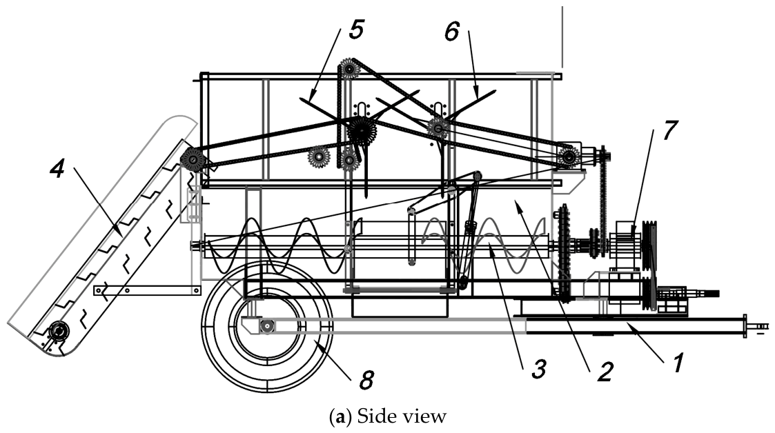
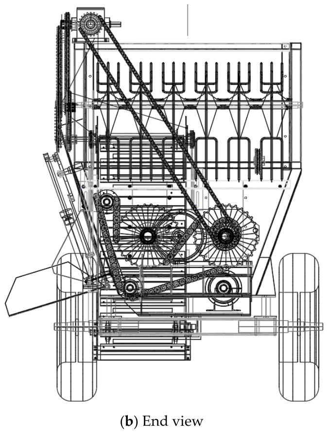
Based on the above considerations, a feed mixer-distributor was developed consisting of a frame (1), a hopper (2) with a capacity of 3.0 m3, a horizontal auger (3), a loading conveyor (4), leveling–mixing shafts (5, 6), drive mechanisms (7), and wheels (8).
The hopper of the machine is mounted on three load cells, which ensure accurate loading of each feed component according to the feeding ration.
At present, Patent of the Republic of Kazakhstan No. 35587 for the invention “Feed mixer-distributor” has been obtained for the feed mixer-distributor design equipped with the new leveling device.
Figure 1 and Figure 2, as well as all photographs and engineering illustrations presented in this paper, were developed and prepared by the authors as part of the present research.
Thus, a new feed mixer-distributor equipped with loading and leveling–mixing devices is being developed to reduce energy consumption and accelerate the mixing process of feed mixture components.
The structural and technological scheme of the developed feed mixer-distributor is shown in Figure 1.
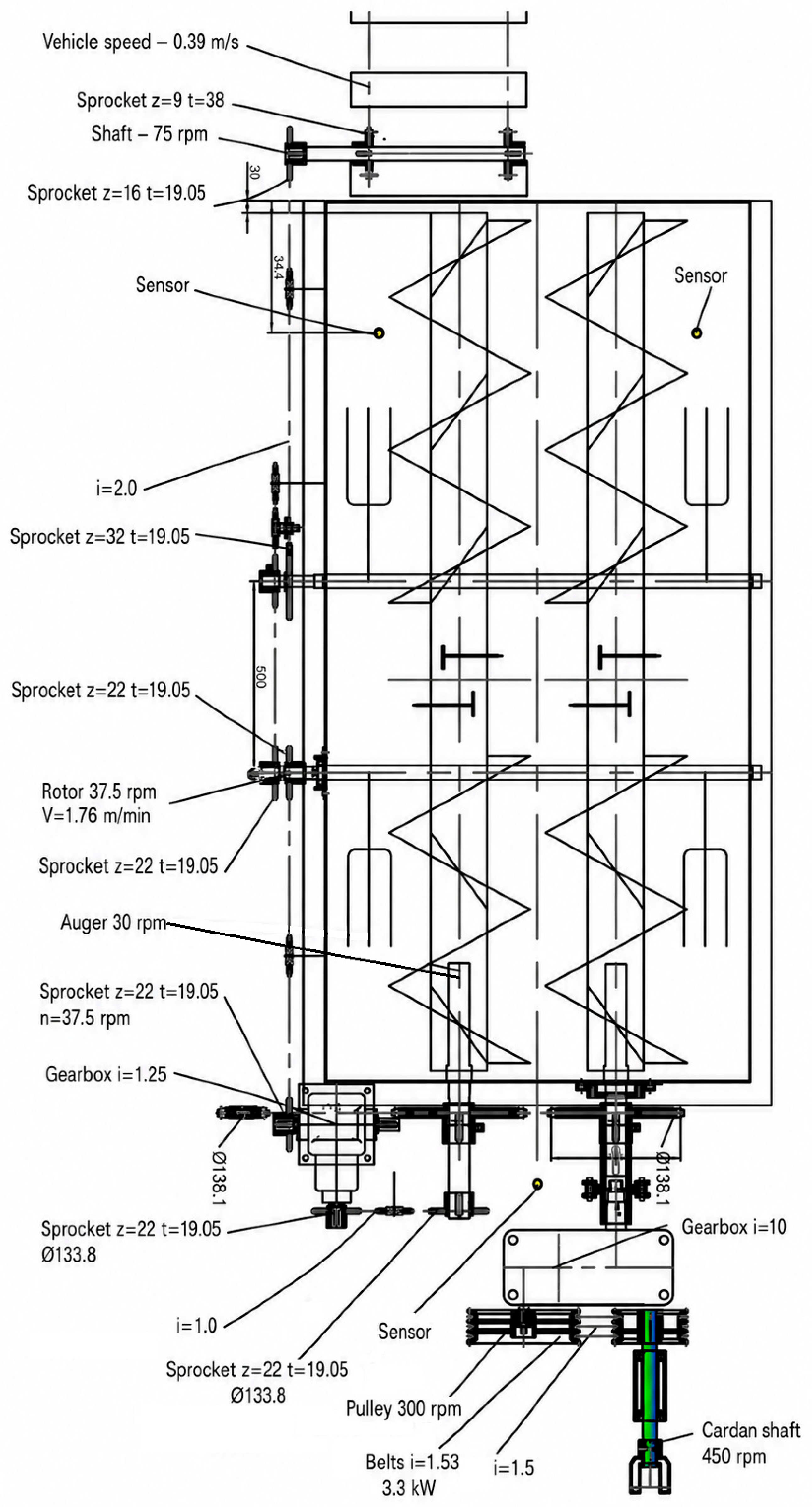
The kinematic scheme of the developed feed mixer-distributor is presented in Figure 2.
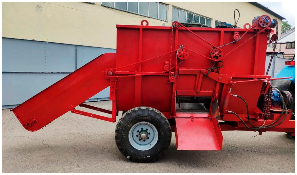
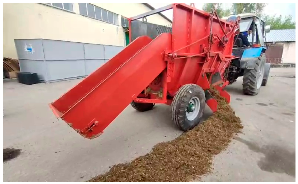
At present, the engineering documentation has been developed, and an experimental prototype of the compact feed mixer-distributor has been manufactured (Figure 3).
Factory tests of the feed mixer-distributor were carried out. It was established that all mechanisms operated under the specified operating conditions, and the machine was confirmed to be ready for field testing and experimental investigations.

5.2. Theoretical Determination of the Rotational Speed of the Leveling–Mixing Finger Shaft

According to the structural and technological scheme, the horizontal auger collects the feed mass in the central part of the hopper, and after a certain lifting height is reached, the leveling finger shaft transports the feed mixture toward the end walls of the hopper. In this case, the feed mixture is not lifted to the point of collapse, which contributes to reducing the energy consumption and mixing time required to achieve the target mixture uniformity.
When substantiating the parameters of the finger shaft to ensure proper operation of the leveling device, it is important to determine the rational rotational speed of the shaft.
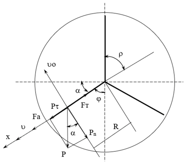
At the rational rotational speed, the fingers should transport the feed mass without scattering it, and at a certain inclination angle, the feed mixture should separate from the finger surface, thereby ensuring accelerated dual-circuit mixing of the feed mass in cooperation with the horizontal auger (Figure 4).
Preliminary inclined-plane tests showed that the feed mixture began to slide from the steel surface at an inclination angle of α = 38°. These tests were used only for a preliminary assessment of the frictional behavior of the feed mixture. For the final kinematic calculations, the experimentally determined dynamic coefficient of friction, f = 0.57, was used.
The physical and mechanical properties of the feed mixture were additionally determined before the experiments. The moisture content of alfalfa hay was 7.17%, silage 42.5%, and the prepared total mixed ration 40.5%. The bulk density of chopped alfalfa hay was 92.2 kg/m3, silage 236 kg/m3, and the prepared total mixed ration 210 kg/m3. During the mixing process, the auger knives reduced the average particle size of the fibrous components to 30–38 mm.
Under these physical and mechanical properties, the dynamic coefficient of friction determined experimentally was adopted for the final theoretical calculations.
The initial moisture content, particle size, and component composition of the feed mixture affect its frictional properties and, consequently, the values of the circumferential velocity and feed movement velocity. Therefore, the obtained analytical relationships are valid for feed mixtures having physical and mechanical properties close to those determined in the present study.
For the final calculation of the rational kinematic mode, the condition of finger disengagement from the monolithic feed mass was considered at a finger rotation angle of α = 20°. At this angle, smooth release of the fingers from the monolithic feed mass is ensured when the friction force is balanced by the resultant of the tangential component of the gravitational force and the centrifugal force.
The value of the circumferential velocity υo or the rotational speed of the finger shaft can be determined by considering the equilibrium of the system under static conditions.
It is well known that when inertial force is introduced into the system, all equations of statics can be applied [30].
In our opinion, a certain critical value of the circumferential velocity or rotational speed of the finger shaft may be considered a rational operating value. This is because, during operation, the rotating fingers generate vibrations in the system, resulting in a reduction in the friction coefficient.
Based on the above considerations, the equilibrium equation of the forces acting on the feed mixture at a finger angle of α = 20° can be written as follows:
Fx = Fa + FT = 0
where Fa—is the centrifugal inertial force acting on the feed mixture with mass m, N;
—is the tangential component of the gravitational force, N;
FT—is the friction force, N.
m υ o 2 R + m   g   s i n α m   g   c o s α   f = 0 , υ o 2 R = f g   c o s α g   s i n α
where m is the mass of the feed mixture located on the finger surface, kg;
υo is the circumferential velocity of the finger shaft, m/s.
From Equation (2), the circumferential velocity of the finger shaft can be determined as follows:
υ o = g R ( f c o s α s i n α )
From Equation (3), the minimum rotational speed of the leveling–mixing finger shaft can be determined from the known value of the circumferential velocity υo:
υ O π n 30 R , n 30 υ O π R .
To analyze the motion of the feed mass on the finger surface, the following differential equation is formulated:
m d υ d t = F a + P τ F T ,
m d υ d t = m υ O 2 R + m g sin α m g cos α f , d υ d t = υ O 2 R + g sin α g f cos α d υ = υ O 2 R + g sin α f cos α d t .
The process of feed mass movement occurs within the range of variation of the angles φ and α. In this case, the time interval tφ can be determined depending on the rotation of the fingers through the angle φ:
t φ = 60 n φ 360 = φ 6 n = φ 6 30 υ o π R = π R φ 180 υ O .
To determine the velocity of movement along the finger surface, Equation (6) should be integrated over the velocity range from 0 to υm and over the time interval from t to tφ:
0 υ m 0 d υ = υ O 2 R + g sin α f cos α 0 t φ d t .
υ m = υ O 2 R + g sin α f cos α t φ .
Substituting this value into Equation (9), we obtain:
υ m = υ O 2 R + g sin α f cos α π R φ 180 υ O , υ m = π φ υ O 180 + g π R φ 180 υ O sin α f cos α .
Thus, an analytical expression was obtained for determining the velocity of feed mass movement along the finger surface of the leveling–mixing shaft.
Both commercially available feed mixer-distributors and the feed mixer-distributor developed in this study are intended for the preparation of total mixed rations (TMR) consisting of silage, haylage, hay, and concentrate feed. More than 80% of the mixture is represented by silage and haylage, which are characterized by high moisture content, whereas hay and concentrate feed constitute a relatively small proportion of the total mixture.
The moisture content and particle size of silage and haylage are known to be important quality characteristics determined during forage production. During feed preparation, the proportions of the individual components are established according to the prescribed ration formulation. Under practical farm conditions, silage and haylage have stable moisture content and bulk density, which remain unchanged during the mixing process. Therefore, investigating the influence of different component ratios, moisture contents, and other physicomechanical properties of the feed materials was beyond the scope of the present study.
At present, production-scale trials of the developed feed mixer-distributor have been carried out at the dairy farm of “Aidarbayev E.”, located in the Enbekshikazakh District of the Almaty Region.
Consequently, the performance results obtained in this study should not be generalized to all possible ration structures. The reported mixing uniformity, mixing time, and power consumption are valid for the tested feed formulation and the measured physical and mechanical properties of the feed components. Further experimental investigations are required to evaluate the influence of different roughage-to-concentrate ratios, moisture contents, particle-size distributions, and hopper filling rates on the performance of the proposed feed mixer-distributor.
Additional experiments were conducted to determine the initial average particle size, moisture content, and bulk density of silage, haylage, and chopped hay. Subsequently, a total mixed ration was prepared, and its average particle size, moisture content, and bulk density were also determined (Table 2). The prepared feed mixture formed a homogeneous mass with an average particle length of 13.7 mm. The relatively small average particle size of the prepared mixture indicates a high degree of mixture homogeneity achieved within the minimum mixing time.
Furthermore, the theoretical and experimental investigations presented in this study were focused on determining the rational kinematic operating parameters of the leveling–mixing shafts. In particular, the velocity of feed particle movement along the finger surface was analytically determined. The theoretical model considered only the sliding motion of feed particles along the steel surface of the fingers and did not account for the energy required to separate the monolithic feed mass, transport the material by the horizontal auger, or lift the feed mass in the central part of the hopper. These aspects were beyond the scope of the present study and will be addressed in future investigations conducted by the research team.
It should also be noted that the proposed theoretical model does not explicitly account for cohesion, internal friction within the feed layer, layer thickness, entanglement of fibrous particles, or inter-particle interactions. These factors may influence force transmission and the actual circulation pattern of moist fibrous total mixed rations. Therefore, the obtained analytical expressions should be considered applicable primarily to feed mixtures with physical and mechanical properties close to those investigated in the present study. The influence of these factors will be examined in future studies using a more detailed mechanical or simulation-based model.
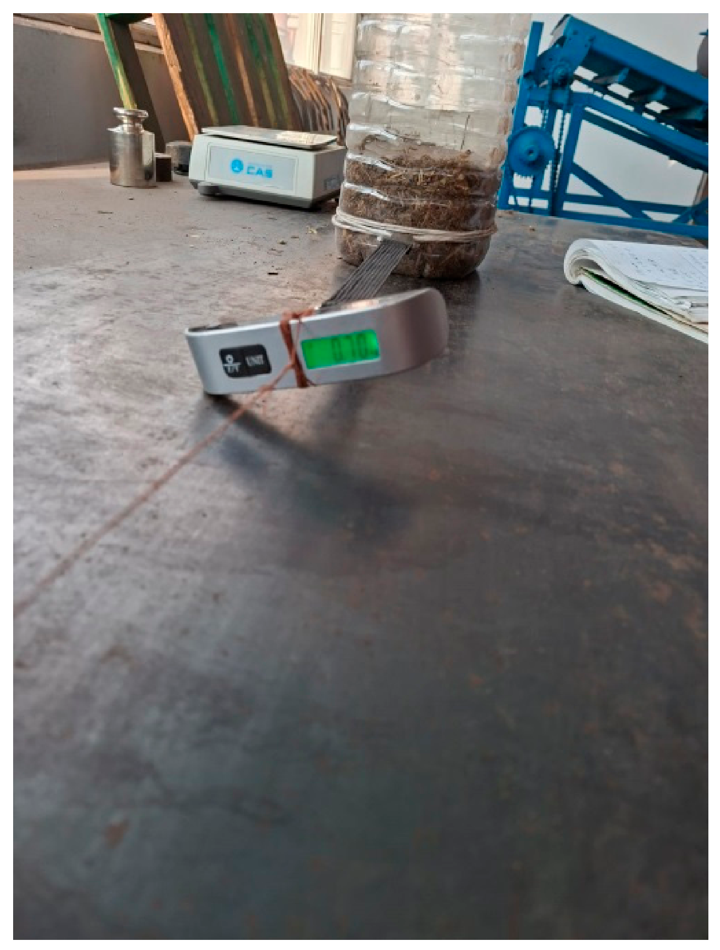
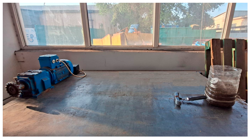
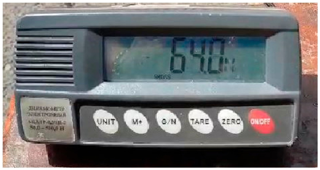
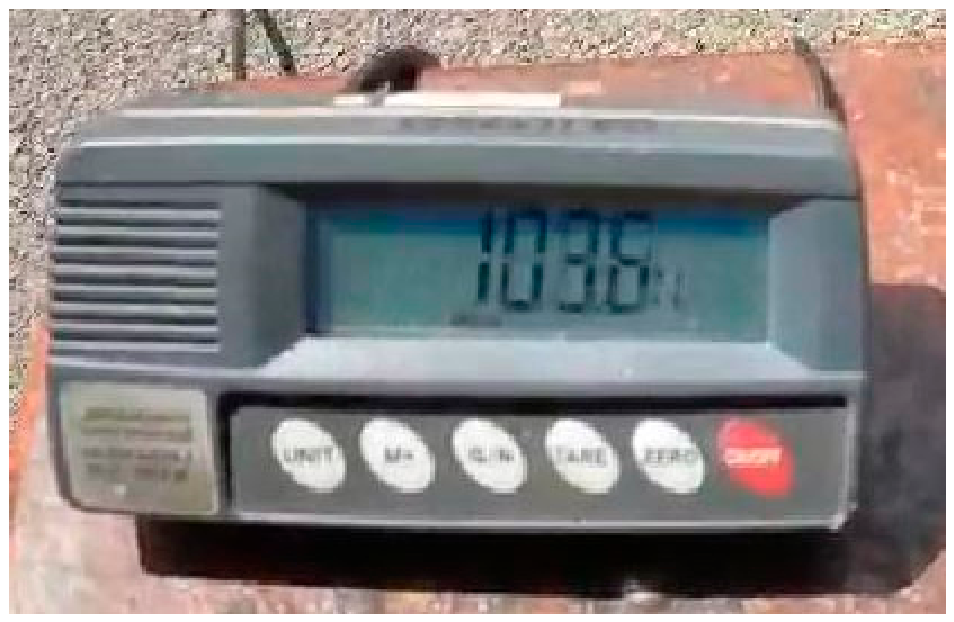
To experimentally determine the dynamic coefficient of friction between the feed material and the steel surface, a laboratory test rig was developed consisting of a gear motor, a bottomless plastic container, and an F-1976 electronic dynamometer. The bottomless container was connected to the output shaft of the gear motor by a thin cord passing through the electronic dynamometer (Figure 5). The operating principle of the test rig was based on moving the feed sample over a steel surface at a constant velocity while continuously measuring the friction force using the electronic dynamometer.
The bottomless container was filled with a feed mixture consisting of chopped hay, haylage, and corn silage. The moisture content of the feed mixture was 48.3%, and its bulk density was 210 kg/m3.
In the experiments, the output shaft of the gear motor rotated at 119 min−1, and the shaft radius was 0.015 m. When the electric motor was switched on, the cord was wound around the output shaft, thereby providing a constant translational velocity of the bottomless container equal to 0.187 m/s. The mass of the feed mixture inside the container was 1.261 kg, and the length of the steel test surface was 1.2 m. During the experiments, the readings of the electronic dynamometer were continuously recorded using a smartphone (Figure 6).
During the five experimental trials, 13 dynamometer readings were recorded. The measured pulling force ranged from 0.66 to 0.75 kgf, with an average value of 0.71 kgf. Based on the experimental data, the average dynamic coefficient of friction between the feed mixture and the steel surface was determined to be 0.57.
The total variance was 0.0107. For f = 13 − 1 = 12 degrees of freedom and a confidence level of 0.95, the critical value of Student’s t-distribution was tα = 2.179.
At the selected confidence level, the confidence interval of the friction force was 0.6475–0.7725 kgf. All experimentally obtained friction-force values were within this confidence interval, confirming the statistical reliability of the experimental results.
In addition, the standard deviation, confidence interval, and coefficient of variation were determined for all other experimental series.
It is well known that dry forage particles begin to slide on an inclined surface at inclination angles of 27–30°, whereas moist fibrous feed materials begin to slide at inclination angles of 35–38°. During operation, the feed mixture is continuously subjected to the motion and vibration of the fingers of the leveling–mixing device. Moreover, the experimentally determined dynamic coefficient of friction of the feed mixture is relatively low.
Under the condition of maximum hopper filling, the fingers can disengage from the monolithic feed mass at a finger rotation angle of α = 20°. At this position, the condition of force equilibrium is satisfied when the friction force is equal to the resultant of the tangential component of the gravitational force acting on the feed mixture and the centrifugal force. Consequently, the selected rotational speed of the finger shaft provides the required equilibrium, ensuring smooth disengagement of the fingers from the monolithic feed mass at α = 20°.
Accordingly, the circumferential velocity of the finger shaft was determined using Equation (3) for α = 20°. Considering the finger radius R = 0.4 m, the dynamic coefficient of friction f = 0.57, and v0 = 0.866 m/s, the minimum rotational speed of the finger shaft was calculated as n = 20.7 min−1.
Using these parameters, the velocity of feed mixture movement along the finger surface was determined from Equation (10) as a function of the finger rotation angle α.
Thus, the theoretical analysis established the rational rotational speed of the finger shaft. Considering that the feed mass is continuously subjected to the motion and vibration of the rotating fingers during operation, the calculated rotational speed of n = 20.7 min−1 can be regarded as the rational kinematic operating mode of the leveling–mixing shaft.
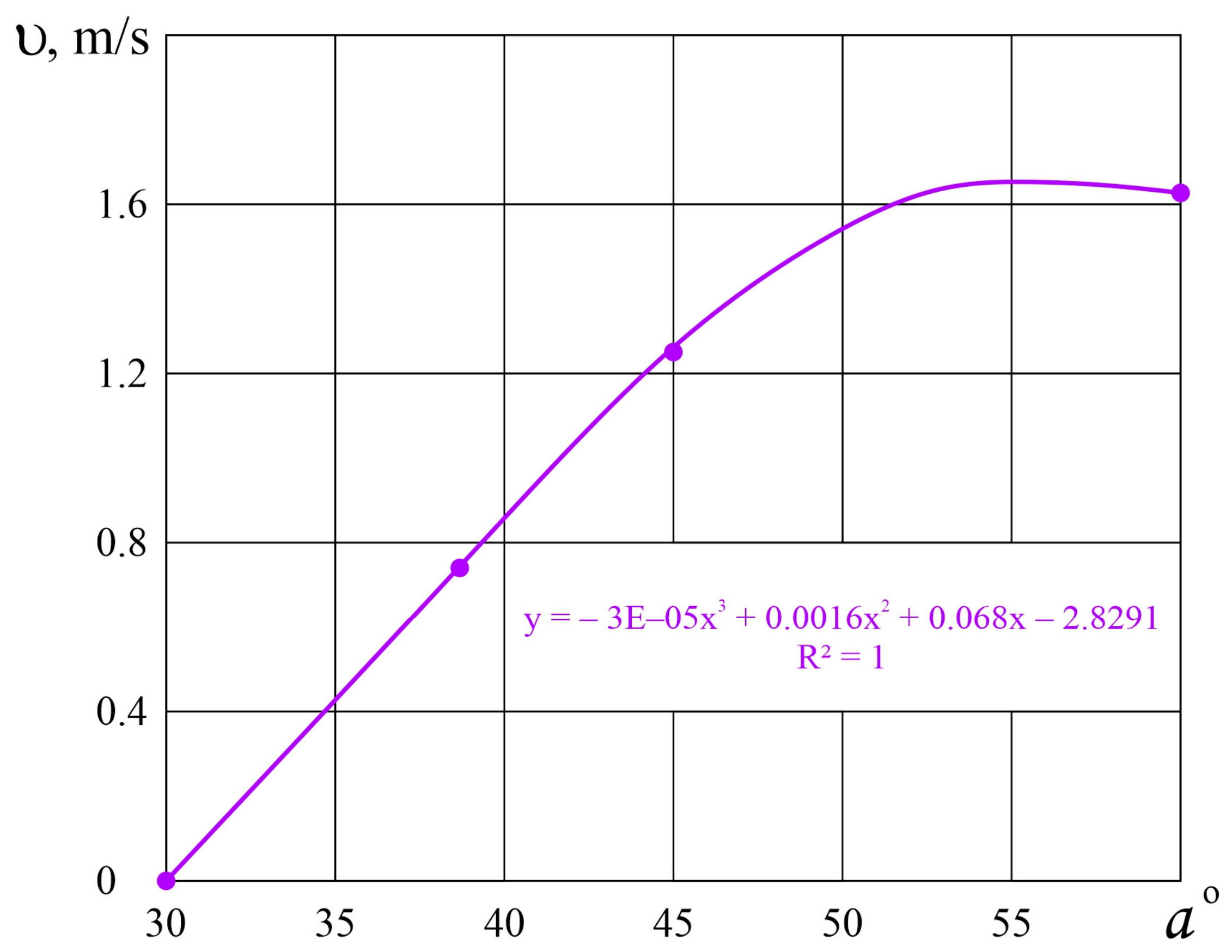
Figure 7 shows the variation in the feed mass movement velocity vm as a function of the finger rotation angle α. In the calculations, the angle φ was varied according to the corresponding value of α. For example, at α = 30°, φ = 60°.
Figure 7 shows that at the finger rotation angle α = 20°, the velocity of particle movement along the finger surface was equal to zero. This indicates that, at α = 20°, the resultant force acting on the feed particles is equal to zero. Under these conditions, the circumferential velocity v0 = 0.866 m/s corresponds to the equilibrium state, at which the driving force responsible for the movement of the feed mixture along the finger surface becomes zero. This confirms the consistency between the analytical expressions represented by Equations (3) and (10).
It should also be noted that, at finger rotation angles of α = 25–30°, the velocity of feed mixture movement along the finger surface ranged from 0.5 to 0.94 m/s. From a practical point of view, this velocity range can be considered rational for transporting the feed mixture toward the end walls of the hopper. However, the validity of this theoretical prediction should be verified experimentally.
At α > 40°, the feed mass is directed toward the monolithic feed layer, and due to the velocity υm, the feed mixture becomes partially compacted. Thus, the rational value of the feed mass movement velocity along the finger surface, at which the feed mixture freely moves toward the end walls of the hopper, is υm = 0.7 m/s. This confirms the validity of the obtained analytical expression.
If the circumferential velocity exceeded the calculated critical value of 0.866 m/s, the feed movement velocity would increase, leading to scattering of the feed mass and unstable operation of the leveling–mixing device.
Therefore, during the development of the structural and technological scheme of the feed mixer-distributor, a rotational speed of n = 20 min−1 was selected as the operating mode of the leveling–mixing shaft.
Based on the above, it can be concluded that the main advantage of incorporating the leveling–mixing shaft into the feed mixer-distributor design is the reduction in energy consumption and the acceleration of the mixing process.
Therefore, to confirm the validity of the developed structural and technological schemes and the theoretical investigations, experimental studies should be conducted.

5.3. Laboratory Experiments for Analyzing the Operation of the Kinematic Modes and Determining Mixture Uniformity Depending on the Operating Time of the Feed Mixer-Distributor Equipped with a Leveling–Mixing Device

5.3.1. Substantiation of the Kinematic Modes of the Leveling–Mixing Device

Laboratory experiments of the experimental prototype of the feed mixer-distributor were carried out on the territory of the research center.
For the experiments, 100 kg of hay, 200 kg of silage, and 50 kg of crushed grain and wheat were prepared. To accelerate the preparation process, hay was initially loaded into the hopper to ensure rapid grinding by the knives mounted on the auger flights. Silage, crushed grain, and the remaining feed components were then added.
During the preliminary testing of the feed mixer-distributor, the PTO rotational speed was 450 min−1, the auger rotational speed was nr = 30 min−1, and the rotational speed of the leveling finger shaft was ns = 20 min−1.
During operation of the feed mixer-distributor, after a certain lifting height of the feed mass is reached, the leveling–mixing finger shaft divides the mass into two flows. After rotating from the vertical position, the fingers begin transporting the feed mass toward the end walls of the hopper. This process occurs during each rotation of the finger shaft; therefore, continuous dual-circuit mixing takes place, which should contribute to accelerated achievement of the required mixture uniformity.
The main performance indicator for all feed mixer-distributors is the ability to ensure the required mixture uniformity. According to zootechnical requirements, the mixture uniformity should be 90% for cattle, 75–80% for sheep, and at least 80% for pigs [31]. Therefore, during the experimental investigations, experiments were conducted to determine the uniformity of the feed mixture depending on the operating time of the feed mixer-distributor.
Initially, experiments were carried out to determine the uniformity of feed mass distribution along the feeding front.
For the experiments, 70 kg of hay, 210 kg of silage, and 42 kg of crushed grain were loaded into the hopper of the feed mixer-distributor. The total feed mixture mass was 322 kg (Figure 8).
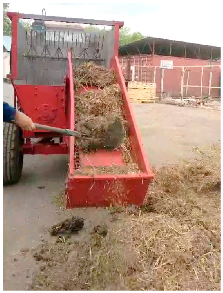
After six minutes of operation of the feed mixer-distributor, the feed mixture was unloaded onto a level surface to determine the mass distribution along the feeding front (Figure 9).
The mass of feed per linear meter of the feeding front was determined from the unloaded feed mixture (Table 3).
σ = m i m f 2 n = 3.05 9 = 0.582 .
The coefficient of variation is determined using the following equation:
υ = σ 100 m f = 0.582 100 12.9 = 4.5 % .
Uniformity of feed mass distribution:
O = 100 υ = 100 4.5 = 95.5 % .
The results of the laboratory experiments showed that the experimental prototype of the feed mixer-distributor performs the technological process of feed mass distribution along the feeding front in accordance with zootechnical requirements and ensures high-quality distribution with a uniformity exceeding 90%.
It should also be noted that, with the discharge gate fully opened, the average mass of unloaded feed was 12.9 kg.
At the same time, the required single feed distribution rate should be within the range of 8–10 kg; therefore, the feed mixer-distributor ensures feed distribution in accordance with zootechnical requirements.
Experimental studies aimed at substantiating the parameters of the feed mixer-distributor were carried out under farm conditions at “Tobylgy Agro Group”, Ili District, Almaty Region.
Under farm conditions, there was a need to prepare a feed mixture for fifty cows for three feeding cycles per day.
According to the feeding ration, a feed mixture consisting of 250 kg of silage, 84 kg of hay (alfalfa), and 50 kg of crushed barley was prepared for a single feeding cycle, with a total mass of 384 kg.
During the experimental investigations, the required power consumption was determined using a TRK-0.5 strain gauge sensor and an ACD-1R-0.5 electronic dynamometer.
In the experimental prototype, the auger rotational speed was regulated by changing the PTO rotational speed of the tractor. During the experiments, the auger rotational speed was 30 min−1. Previous studies showed that, in all similar machines, the rotational speed of the horizontal auger is generally regulated within the range of 24–30 min−1. The rotational speed of the leveling shaft during the experiments was 20 min−1.
After loading the prepared feed mixture components into the hopper of the feed mixer-distributor, a tracer component consisting of 3 kg of wheat was added. A stopwatch was then started.
To determine the effect of mixing time on mixture uniformity, samples were collected during operation of the feed mixer-distributor. The samples were taken after 2, 4, 6, and 9 min of operation.
To obtain each sample, the discharge gate of the mixer was slightly opened, and a small portion of the feed mass was unloaded. From this unloaded mass, 10 samples weighing 70–80 g each were collected. The samples were taken using a 0.3 L cup.
In conventional laboratory mixing studies, samples are typically collected from different locations within the mixer after the working bodies have been stopped. However, this approach is not suitable for feed mixer-distributors because interruption of the mixing process is not recommended under practical operating conditions. The mixer is designed to operate continuously until the complete unloading of the feed mass from the hopper.
Therefore, the samples were collected from the discharged feed mixture after unloading. Since the entire feed mass was uniformly distributed along the feed bunk during the unloading process, multipoint sampling was performed by collecting samples at 3 m intervals along the length of the distributed feed layer.
Accordingly, sampling from different sections of the distributed feed mixture represented the feed mass originating from different regions of the hopper. This sampling procedure provided a representative assessment of mixture uniformity over the entire volume of the discharged feed and corresponded to the actual operating conditions of the feed mixer-distributor.
At the same time, it should be acknowledged that this sampling procedure does not provide a direct assessment of the internal mixing state at different hopper depths before unloading. Direct sampling from different hopper zones was not performed because interruption of the mixing process is not recommended under practical operating conditions for feed mixer-distributors. Therefore, the obtained uniformity values characterize the discharged feed mixture under real operating conditions. Direct internal sampling or non-invasive flow visualization may be considered in future studies.
During the processing of the experimental data, the tracer component was separated from each sample and its mass was determined.
The experimental investigations were carried out using a typical total mixed ration for dairy cattle. Comparative mixing tests for different feed formulations were not included in the scope of the present study.
The mixture uniformity was not assessed visually but was determined quantitatively based on the distribution of the tracer component in the collected samples.
It should also be noted that the mass of each sample differed during sampling. Therefore, during the processing of the experimental data, the average sample mass was first determined.
For each sample, the reduced mass of the tracer component corresponding to the average sample mass was then determined as follows:
m k p = m c m k i m o i ,
where m c —is the average mass of the samples, g, determined using Equation (12);
m k i —is the mass of the tracer component in the i-th sample, g;
m o i —is the mass of the i-th sample, g.
m c = i c n m k i n ,
The results of processing the experimental data obtained after six minutes of operation of the feed mixer-distributor are presented below (Table 4).
The experiments aimed at determining the mixture uniformity were conducted at five operating time levels with three replications at each level. The homogeneity of variances was evaluated using Cochran’s criterion. The calculated Cochran value was 0.33, while the tabulated value was 0.53, confirming the homogeneity of variances and the reliability of the obtained experimental results.
δ = i = 1 n m k n i m c 2 n 1 = 0.086 9 = 0.0948 .
Similarly, the coefficient of variation for the second experimental dataset was calculated as follows:
υ = G 100 m c = 0.095 100 2.33 = 4.077 = 4.1 .
Uniformity of the mixing process:
O = 100 − υ = 100 − 4.1 = 95.9%.
Thus, the experimental prototype of the compact feed mixer-distributor ensures the preparation of total mixed rations with a mixture uniformity of 95.9% for all types and age groups of animals.
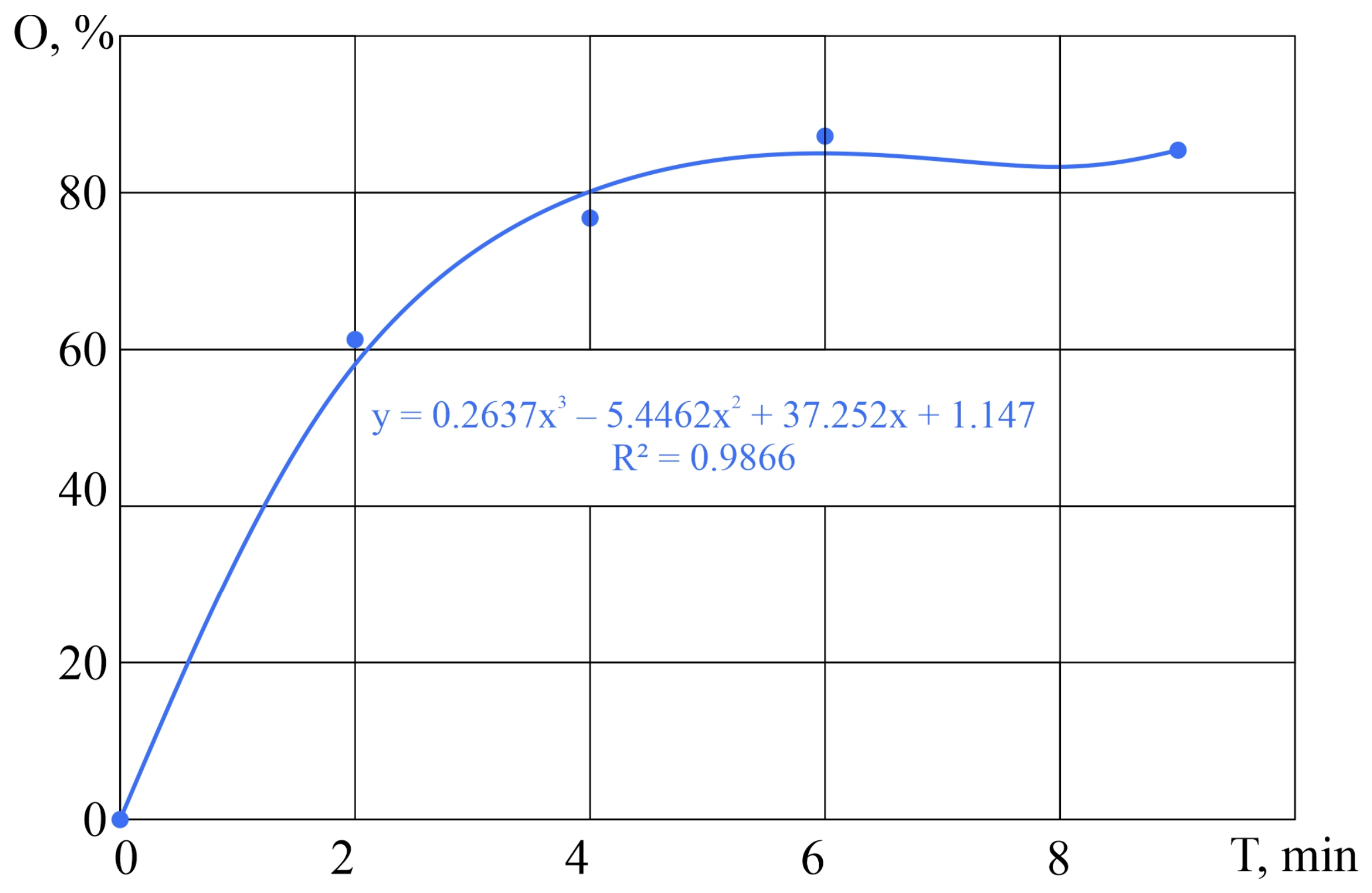
After processing the experimental data, the mixture uniformity values corresponding to 2, 4, 6, and 9 min of mixer operation were determined (Figure 10).
The graph shows that, after 5–6 min of operation, the mixture uniformity reaches 90%, after which the change in uniformity stabilizes at approximately the same level. Therefore, for the proposed feed mixer-distributor, an operating time of 5–6 min can be considered the optimal duration of the mixing process.
In conventional feed mixers, the mixing process occurs by lifting the feed mixture until collapse. In this case, the feed mass collapses in large portions and is subsequently transported toward the center of the hopper. To distribute the smaller components throughout the entire feed mass, the collapse process must be repeated several times.
In the experimental prototype of the feed mixer-distributor, two leveling finger shafts are installed in the upper part of the hopper. During operation of the machine, the finger shafts transport the feed mass toward the end walls of the hopper after a certain lifting height is reached.
In this case, the feed mixture in the central part of the hopper is not lifted to the point of collapse, and a small portion of the mass is immediately transported toward the end walls of the hopper. As a result, accelerated dual-circuit mixing occurs, which reduces the mixing time.
The experimental investigations were conducted at a finger shaft rotational speed of 20 min−1. Under these operating conditions, one complete revolution of the finger shaft was performed every 3 s. The finger shaft was equipped with three rows of fingers, each of which passed through the working zone once per second, thereby transporting the feed mass toward the end walls of the hopper.
It should be noted that the two finger shafts operate simultaneously and independently. Consequently, continuous dual-circuit mixing is performed every second throughout the mixing process. During the initial stage of mixing, the feed components are intensively redistributed throughout the entire hopper volume. After 5 min of operation, the mixture uniformity exceeds 90%, after which the mixing process reaches a stable state.
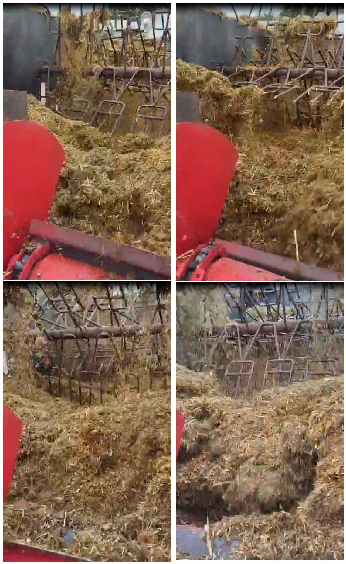
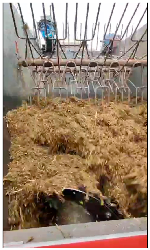
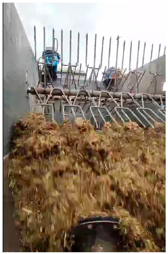
Video recordings of the mixing process showed that when the leveling–mixing fingers rotated through an angle of 25–30°, the feed mass was transported toward the end walls of the hopper. During each lifting cycle performed by the rows of fingers, the feed mass was elevated and subsequently fell back under gravity, after which it was transported toward the center of the hopper by the horizontal auger. As a result, a continuous dual-circuit circulation of the feed mass was maintained throughout the mixing process.
Figure 11 presents a sequence of video frames illustrating the operation of the leveling–mixing finger shaft and the corresponding pattern of feed mass movement.
During the experiments, the rotational speed of the finger shaft was maintained at n = 20 min−1. Under these operating conditions, the movement of the feed mass occurred at a relatively low velocity, allowing the mixing process to be clearly observed and documented using conventional video recordings of the leveling–mixing finger shaft.
The video recordings provided qualitative confirmation of the proposed dual-circuit movement of the feed mass. However, the present study did not include quantitative internal-flow measurements such as particle image velocimetry, high-speed imaging, discrete-element simulation, or detailed tracer trajectory analysis. Therefore, the observed movement pattern should be interpreted as experimental visual evidence of the proposed mechanism rather than as a complete quantitative description of the internal flow field. Future studies will focus on quantitative visualization and simulation of feed mass circulation inside the hopper.
Therefore, the presented graph (Figure 10), showing the change in mixture uniformity depending on machine operating time, represents a characteristic relationship for the feed mixer-distributor equipped with the leveling–mixing device.
The polynomial equation was used as an empirical approximation of the experimentally obtained relationship between mixture uniformity and mixing time. It was not intended to represent a universal physical mixing-kinetics model. The purpose of this approximation was to describe the observed stabilization of mixture uniformity after 5–6 min of operation and to determine the time interval at which further mixing provides only a minor increase in uniformity.
This relationship can be expressed by the following equation:
O = 0.263 T 3 5.4462 T 2 + 37.252 T + 1.147 ,
where T is the operating time of the feed mixer-distributor, min.
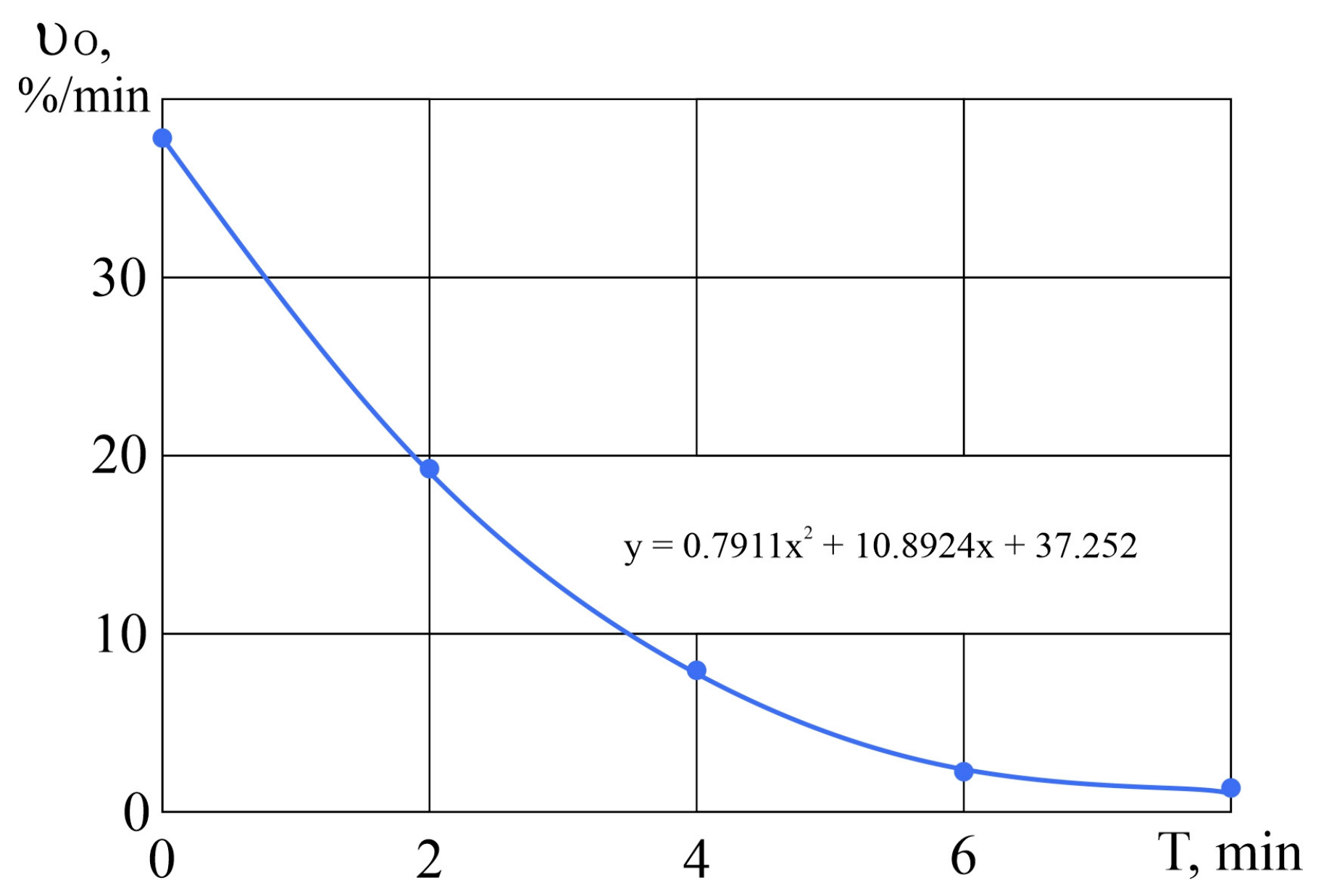
Differentiating this equation, the rate of change in mixture uniformity υo can be obtained as follows:
υ o = d O d T = 0.2637 T 3 5.4762 T 2 + 37.252 T + 1.147 = =   0.7911 T 2 10.8924 T + 37.252
To clearly illustrate the rate of change in mixture uniformity depending on the duration of the mixing process of the feed mixer-distributor, a graphical representation of the obtained function is presented in Figure 12.
This graph clearly demonstrates that the optimal operating duration for the proposed feed mixer-distributor design is 5–6 min.
According to the technical specifications of modern feed mixers, the mixing time generally ranges from 6.0 to 7.0 min [32]. The above comparison was performed using the technical characteristics of commercially available feed mixer-distributors reported by manufacturers and in the technical literature because compact serial feed mixers with hopper capacities below 3 m3 are currently almost unavailable for direct comparative experimental investigations. The comparison of the mixing duration was performed using the technical specifications of commercially available feed mixer-distributors because compact serial machines with hopper capacities below 3 m3 and operating according to the proposed technological principle are currently unavailable. When the leveling–mixing device is used, the optimal mixing time decreases to 5.0–6.0 min, indicating an acceleration of the mixing process by 15.4%.
The theoretical investigations showed that the rational rotational speed of the finger shaft is n ≥ 20 min−1, and that feed mixture release from the surface of the fingers of the leveling–mixing shaft should occur at finger rotation angles of 20–30°. The results of the experimental studies demonstrated that, at a finger shaft rotational speed of n ≥ 20 min−1, smooth movement of the feed mass toward the end walls of the hopper was observed (Figure 13 and Figure 14).
The figures show that, at the initial stage of feed mass discharge, the fingers are positioned vertically, whereas at the final stage of discharge the fingers are inclined at an angle of approximately 20–30°, which confirms the validity of the theoretical investigations. It should also be noted that stable operation of the finger shaft was observed during the experiments, i.e., the feed mixture slid from the finger surface smoothly and without scattering.
Thus, these results confirm the validity of the presented investigations and the rationality of the kinematic modes of the finger shaft determined through theoretical analysis.
To experimentally validate the theoretical results obtained for determining the optimal rotational speed of the leveling–mixing device, a series of experiments was conducted at different finger shaft rotational speeds of 10, 20, and 24 min−1.
To maintain a constant rotational speed of the horizontal auger (na = 30 min−1), the rotational speed of the leveling–mixing shaft was varied by replacing the sprockets mounted on the input shaft of the bevel gearbox.
The experiments were carried out at the “Aidarbayev E.” farm. During each experimental trial, the hopper of the feed mixer-distributor was loaded with 300 kg of silage, 300 kg of haylage, and 50 kg of chopped alfalfa hay.
After loading all feed components, a tracer component (4.5 kg of wheat) was added to the hopper. The stopwatch was started simultaneously with the activation of the mixer-distributor mechanisms. After 6 min of operation, the prepared feed mixture was discharged onto the feed bunk. Ten samples, each with a volume of 0.3 L, were collected from the discharged feed mixture at 2.0 m intervals along the length of the feed bunk.
During data processing, the tracer component was separated from each sample. The mean tracer content, standard deviation, coefficient of variation, and mixture uniformity were subsequently determined (Table 5).
As shown in Table 5, at the minimum finger shaft rotational speed, the feed mixture was transported at a relatively low velocity, resulting in a slow mixing process.
When the finger shaft rotational speed exceeded 20 min−1, the velocity of feed particle movement increased considerably. Under these conditions, the feed mixture was transported in relatively large portions while being simultaneously conveyed by the horizontal auger, which apparently reduced the uniformity of the resulting mixture.
At a rotational speed of 20 min−1, the movement of the feed mass was smooth and uniform. Under these operating conditions, the feed mixture was gradually broken into smaller portions, which were subsequently captured by the horizontal auger, thereby promoting intensive and uniform mixing of the feed components.
The experimental results confirmed the validity of the theoretical analysis. The optimal rotational speed of the leveling–mixing finger shaft was established as n = 20 min−1. At this rotational speed, the mixture uniformity exceeded 90%, satisfying the zootechnical requirements for the preparation of total mixed rations containing concentrate feed and feed additives [31].

5.3.2. Energy Evaluation of the Leveling–Mixing Device

For the energy evaluation, it was necessary to determine the power consumption values during operation of the feed mixer-distributor both with and without the leveling device. Therefore, two experiments were conducted.
In the first experiment, a feed mixture with a specified mass was loaded into the feed mixer-distributor, and the power consumption during operation with the leveling device was determined.
In the second experiment, the same loaded feed mass was used to determine the power consumption of the mixing process without the leveling device.
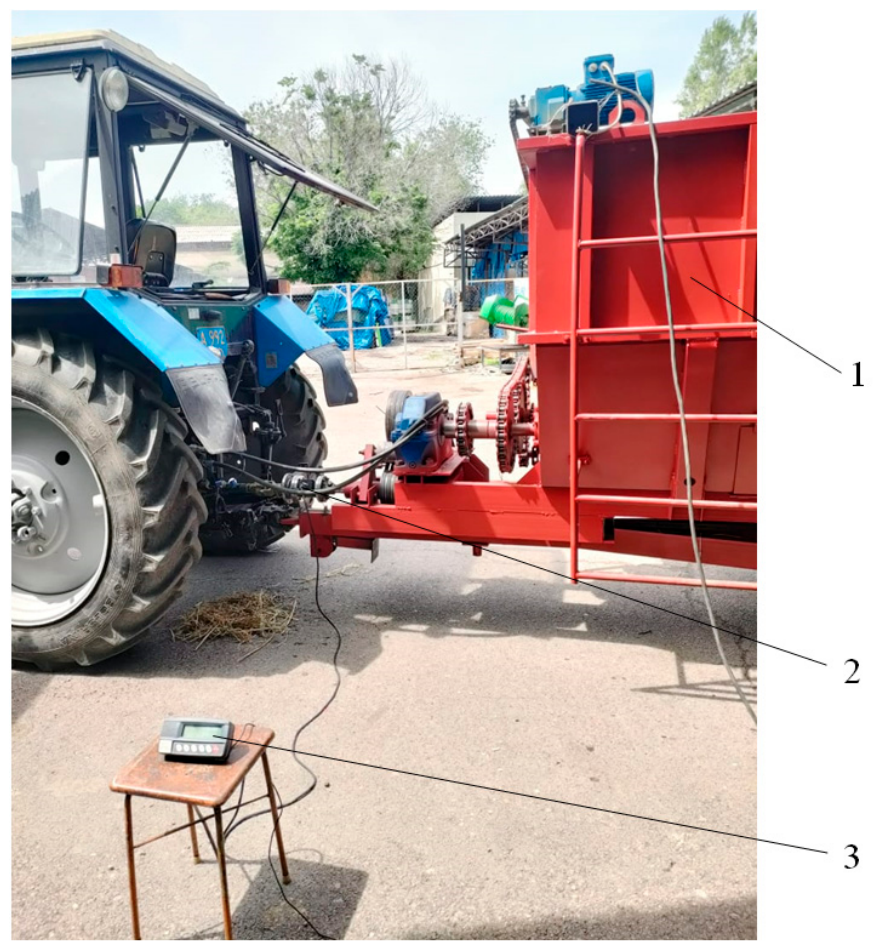
To conduct the above-mentioned experiments, a TRK-0.5 strain gauge sensor was installed on the shaft of the main gearbox and connected through an ACD-1R-0.5 electronic dynamometer (Figure 15).
For the experiments, a feed mixture corresponding to a single feeding cycle for 50 cows was prepared. Considering that the average daily ration per cow under three feeding cycles consists of 15 kg of silage, 5 kg of hay, and 3 kg of compound feed or grain feed, the following quantities were loaded into the hopper of the feed mixer-distributor for one feeding cycle: (15/3) × 50 = 250 kg of silage; (5/3) × 50 = 84 kg of hay; and (3/3) × 50 = 50 kg of crushed barley. The total feed mixture mass was 384 kg.
During the experiments, the strain gauge sensor was installed on the shaft of the main gearbox, while its shaft was connected to the tractor power take-off (PTO) shaft through a cardan shaft.
Under operating conditions, the tractor PTO rotational speed was 450 min−1, the auger rotational speed was 30 min−1, and the rotational speed of the leveling–mixing finger shaft was 20 min−1.
Initially, the operation of the feed mixer-distributor under idle conditions was checked. The rotational speeds of the auger and the leveling shaft corresponded to the above-mentioned operating conditions, and the resistance torque values of the machine working bodies were determined.
The average resistance torque during idle operation of the feed mixer-distributor was M c = 8.3 N·m. In this case, the power consumption during idle operation is determined using the following equation:
N i o = M c ω = M c π n 30 = 8.3 3.14 450 30 = 397 0.4   kW .
Next, all feed mixture components were loaded into the hopper, and the mixing process was carried out for six minutes under full loading conditions. The operating process of the feed mixer-distributor equipped with the leveling–mixing device was recorded using a smartphone. After that, partial unloading of the feed mixture was performed, the tractor PTO was disengaged, and the drive of the leveling–mixing shaft was disconnected. The feed mixture was then reloaded to full capacity, and the operation of the feed mixer-distributor without the leveling–mixing shaft was recorded.
Processing of the experimental data showed that the average resistance torque during operation with the leveling–mixing device was M p c   = 71.5 N·m (Figure 16).
Determination of the average power consumption values for the feed mixer-distributor equipped with the leveling device and without it was based on five experimental replications. For the machine equipped with the leveling device, the standard deviation was 0.18 kW and the coefficient of variation was 5.34%.
For the feed mixer-distributor operating without the leveling device, the standard deviation was 0.29 kW and the coefficient of variation was 6.42%, confirming satisfactory repeatability of the experimental data.
According to the recommendations for planning engineering experiments, a coefficient of variation below 8% corresponds to high experimental accuracy under laboratory conditions, while values of 8–15% are generally considered acceptable for field investigations. Therefore, the obtained coefficients of variation confirm the reliability of the experimental results.
Therefore, the 34% increase in power consumption observed during operation without the leveling–mixing device should be considered a statistically reliable technological effect rather than a random experimental deviation.
Consequently, the power consumption of the machine equipped with the leveling–mixing device was Np = 3.37 kW.
Processing of the operating data obtained for the machine without the leveling–mixing device showed that the average resistance torque was 96 N·m (Figure 17). In this case, the power consumption was Nmd = 4.52 kW.
These data show that operation of the feed mixer-distributor without the leveling–mixing device results in a 34% increase in power consumption compared with operation of the feed mixer-distributor equipped with the leveling–mixing device.
Observation of the machine operating without the leveling–mixing device showed that the feed mass was lifted to a certain height and remained in this position until collapse occurred. This indicates that the collapse process takes place after complete loading of the machine, which additionally contributes to increased energy consumption and longer mixing duration.
Within the scope of the present study, the theoretical and experimental investigations were focused on determining the rational kinematic operating parameters of the leveling–mixing shafts. The energy required for the separation of the monolithic feed mass by the finger shaft, the transportation of the feed mass by the horizontal auger, and the lifting of the feed mass in the central region of the hopper were beyond the scope of the present investigation. These aspects will be addressed in future studies conducted by the research team.
Thus, the results of these experiments confirm that equipping the feed mixer-distributor with a leveling–mixing device reduces the energy consumption and accelerates the mixing process, thereby validating the proposed hypothesis.
As a result of the theoretical and experimental investigations, a new technology for the feed mixing process was proposed, a structural and technological scheme of a feed mixer-distributor equipped with a leveling–mixing device was developed, and the kinematic operating modes of the machine were substantiated. The conducted studies confirmed the validity of both the proposed hypothesis and the theoretical investigations.

6. Discussion

Analysis of existing feed mixer-distributor designs showed that the mixing process in such machines is carried out by lifting the feed mass until collapse occurs. In this process, the lifted feed mixture collapses in large portions and is transported by the horizontal auger toward the center of the hopper, where the feed mass is again lifted until collapse. As a result, the duration of the mixing process required to achieve the target mixture uniformity increases, while the energy consumption associated with lifting the feed mass also rises.
The developed feed mixer-distributor is equipped with a new leveling–mixing device. In this machine, the horizontal auger collects the feed mass in the center of the hopper, and after a certain lifting height is reached, the fingers of the leveling–mixing device direct the feed mixture toward the end walls of the hopper. This dual-circuit mixing process occurs during each rotation of the finger shaft, thereby accelerating the mixing process. Consequently, the developed feed mixer-distributor differs from existing machines both in design and in the operating principle of the mixing process.
Unlike conventional feed mixer-distributors, where the feed mass is repeatedly lifted and allowed to collapse under gravity, the proposed machine performs controlled redistribution of the feed mass during each rotation of the leveling–mixing shafts. This fundamentally changes the internal circulation pattern of the feed mixture and reduces both the duration of the mixing process and the energy required for feed preparation.
The scientific novelty of the proposed design consists not only in the introduction of additional leveling–mixing shafts but also in the implementation of a fundamentally different technological principle based on continuous dual-circuit redistribution of the feed mass.
In conventional feed mixer-distributors, the horizontal augers located at the bottom of the hopper transport the feed mass toward the center, where it is lifted upward. After reaching a certain height, the accumulated feed mass collapses under its own weight. This collapse occurs in large portions. Considerable time is required for the feed mass to be transported to the center before each collapse, and an additional time interval is required before the next collapse occurs. As a result, the mixing process is prolonged, reducing its overall efficiency.
Furthermore, before the feed mass collapses, the auger flights are subjected to a high resisting torque during lifting. Consequently, conventional feed mixer-distributors require heavy-duty reduction gearboxes, drive chains with a pitch of 50.8 mm, and auger flights manufactured from 8 mm thick steel plates. These design requirements substantially increase the manufacturing cost of conventional feed mixer-distributors.
Feed mixer-distributors are intended for the preparation of total mixed rations consisting of silage, haylage, hay, and concentrate feed. In the investigated feed formulation, the main components, silage and haylage, account for approximately 83% of the mixture and have a moisture content ranging from 48% to 60%.
Auxiliary mixing devices are commonly employed in mixers designed for the preparation of dry mixtures and compound feeds. In contrast, conventional feed mixer-distributors for total mixed rations generally employ only horizontal augers as the primary mixing elements without the use of additional mixing devices. Consequently, such machines are characterized by high energy consumption during mixing, long feed preparation times, and the need for expensive drive systems.
In the feed mixer-distributor developed in the present study, the mixing process follows a fundamentally different operating principle. Instead of allowing the accumulated feed mass to rise until collapse, the leveling–mixing finger shafts divide the slightly lifted feed mass into two streams and transport them toward the end walls of the hopper. During one complete revolution of the finger shaft, this transport process is repeated three times. As a result, the intensity of material circulation is significantly increased, thereby accelerating the mixing process. At the same time, a more efficient redistribution and transportation of the feed mass reduce the energy required for mixing.
The developed feed mixer-distributor is equipped with a two-stage cylindrical gearbox. The drive chain has a pitch of 38 mm, and the auger flights are manufactured from 4 mm thick steel plates, resulting in a substantial reduction in the manufacturing cost of the machine.
The scientific novelty of the present study lies in the theoretical and experimental substantiation of a novel continuous dual-circuit mixing process achieved by means of the proposed leveling–mixing device.
Within the framework of this study, analytical expressions were obtained for determining the rational rotational speed of the leveling–mixing finger shaft and the velocity of feed mass movement toward the end walls of the hopper. This represents the scientific novelty and theoretical contribution of the proposed process.
Unlike the mixer designs considered in [10,15,24], where the improvement of the mixing process is mainly achieved by changing the geometry of the main working bodies or by optimizing the loading and mixing parameters, the proposed design introduces an additional leveling–mixing device that changes the internal circulation pattern of the feed mass. This device prevents the feed mixture from being lifted to the point of uncontrolled collapse and instead provides controlled dual-circuit redistribution toward the end walls of the hopper.
Laboratory experiments conducted to validate the theoretically determined kinematic modes of the leveling–mixing finger shaft demonstrated that the feed mixture movement process occurred without feed scattering and with timely release of the feed mass from the finger surface. These results confirm the validity of the theoretical investigations, while the rationality of the determined kinematic modes is supported by the experimental results demonstrating accelerated mixing performance.
It should also be noted that the comparative experiments conducted with and without the leveling device demonstrated the effectiveness of the leveling–mixing device itself. The comparative investigations demonstrated that the proposed mixing principle reduced the optimal mixing time and that operation without the leveling–mixing device resulted in 34% higher power consumption compared with operation of the feed mixer-distributor equipped with the leveling–mixing device. Incorporating this device into the mixer design reduces the energy consumption and accelerates the mixing process.
This result is consistent with the conclusions of Li et al. [11], who showed that the energy intensity of horizontal TMR mixers strongly depends on the interaction between fibrous material and the working bodies. In the present study, the reduction in power consumption was achieved not only by selecting a rational operating mode but also by changing the trajectory of feed mass movement inside the hopper.
It should be emphasized that the present comparison does not demonstrate the superiority of the developed machine over all commercially available compact feed mixer-distributors. The comparative experiments were intended to evaluate the effect of the leveling–mixing device on the operation of the developed prototype under identical operating conditions. Therefore, the obtained results characterize the technological effect of the proposed device within the tested prototype rather than a direct benchmark superiority over commercial machines of comparable capacity.
The obtained reduction in power consumption should be regarded as a positive technological effect because it was achieved without increasing the complexity of the main mixing mechanism and while simultaneously reducing the mixing time. The comparison was performed under identical operating conditions using the same feed mixture and the same feed mixer-distributor, with and without the leveling–mixing device.
However, the power measurements in the present study were based on the total resistance torque measured on the main gearbox shaft. Therefore, the individual contributions of the horizontal augers and the leveling–mixing finger shafts to the total power consumption could not be separated. For this reason, the reported difference in power consumption should be interpreted as the overall energy effect of the proposed mixing principle under the tested operating conditions. Separate measurement of the power demand of each working body will be considered in future studies.
Although standard deviation, confidence intervals, and coefficients of variation were calculated for the experimental series, the number of production-scale trials was limited. Therefore, a full statistical comparison across all operating conditions, including significance testing and effect-size estimation, was not performed in the present study. The reported differences in mixture uniformity, mixing time, and power consumption should therefore be interpreted as experimentally observed technological effects under the tested conditions rather than as universal performance indicators.
It is expected that the efficiency of the proposed device may increase with increasing hopper capacity of the feed mixer-distributor.
One limitation in applying the obtained analytical expressions to other feed materials may be the need to refine the friction coefficient depending on the type of material and its moisture content.
At present, an experimental prototype of the developed feed mixer-distributor has been manufactured. The rational kinematic operating parameters of the machine have been established, and its capability to perform the proposed feed mixing process has been experimentally confirmed. In addition, production-scale tests were conducted at the dairy farm of “Aidarbayev E.”, located in the Enbekshikazakh District of the Almaty Region.
During the production tests, the machine operated for 30 h, during which two interruptions with a total duration of 14 min were recorded. The first interruption resulted from the displacement of the drive pulley due to insufficient fastening reliability on the drive shaft. The second interruption was caused by deformation of one of the fingers of the leveling–mixing shaft. These results indicate a satisfactory level of reliability of the principal mechanisms of the developed feed mixer-distributor. Furthermore, the manufacture and replacement of the finger shaft do not present significant technological difficulties.
Nevertheless, further investigations are required to comprehensively evaluate the durability and long-term reliability of all machine mechanisms. A final assessment will be carried out after the manufacture of a pre-production prototype and the completion of acceptance tests, which will provide a comprehensive evaluation of the operational performance and reliability of the proposed design.
Additional experiments were performed to determine the initial average particle size, moisture content, and bulk density of silage, haylage, and chopped alfalfa hay. Subsequently, a total mixed ration was prepared, and its average particle size, moisture content, and bulk density were also determined (Table 1). The prepared feed mixture formed a homogeneous mass with an average particle length of 13.52 mm. The relatively small average particle size of the prepared mixture indicates a high degree of mixture uniformity achieved within a short mixing period.
The present study reports the average particle length, moisture content, and bulk density of the initial feed components and the prepared feed mixture. However, a complete fiber-length distribution, moisture variability within individual samples, and time-dependent bulk-density evolution during mixing were not determined. These parameters are important for a more detailed interpretation of the mixing process and will be included in future experimental studies.
During the production tests, the hopper of the feed mixer-distributor was loaded with feed mixtures having masses of 400, 450, and 500 kg, thereby evaluating the machine under different hopper filling conditions. The maximum hopper loading corresponded to a volume of 2.5 m3 and a feed mass of 500 kg.
A possible continuation of the present research is the integration of the leveling–mixing device into existing feed mixer-distributor designs. Another promising direction is the application of the obtained analytical expressions for substantiating the kinematic modes of similar leveling, distributing, and mixing devices.

7. Conclusions

  • To accelerate the mixing process, a hypothesis was proposed stating that continuous dual-circuit mixing can be achieved by equipping the feed mixer-distributor with two leveling–mixing finger shafts, which, after a certain lifting height of the collected feed mass is reached, divide it into two flows directed toward the end walls of the hopper. In this case, continuous dual-circuit mixing is performed during each rotation of the leveling–mixing shaft.
A structural and technological scheme and engineering documentation were developed, and an experimental prototype of the feed mixer-distributor was manufactured. The machine consists of a 3.0 m3 hopper, two horizontal augers, two leveling–mixing finger shafts, a loading conveyor, and a drive mechanism.
2.
Theoretical investigations were carried out, and analytical expressions were obtained for determining the circumferential velocity of the fingers of the leveling–mixing device, which should ensure feed movement without scattering and provide timely release of the feed mass from the finger surface when the finger rotation angle exceeds 20°. Calculations showed that the critical circumferential velocity of the fingers was 0.866 m/s, while the rotational speed of the finger shaft was 20 min−1.
Experimental investigations performed at different rotational speeds of the leveling–mixing device demonstrated that the optimal rotational speed of the finger shaft was 20 min−1, at which the mixture uniformity exceeded 90%.
An analytical expression was also obtained for determining the velocity of feed mixture movement along the finger surface. Based on the analytical calculations, the optimal velocity was found to range from 0.5 to 0.94 m/s.
This value corresponds to the rational velocity of feed mixture movement toward the end walls of the hopper.
3.
Laboratory experiments of the feed mixer-distributor were conducted at a rotational speed of the leveling–mixing finger shaft of n = 20 min−1. Under this kinematic mode, the fingers transported the feed mass without scattering, while timely release of the feed mass from the finger surface was ensured at a finger rotation angle of α = 20°.
Special experimental studies showed that the optimal mixing time required to achieve the target mixture uniformity was 5.5 min. This value confirms that the developed machine can achieve the required mixture uniformity within a short mixing time under the tested operating conditions.
Comparative experiments also showed that operation without the leveling–mixing device resulted in 34% higher power consumption than operation with the leveling–mixing device.
All the above results confirm the validity of the selected structural and technological scheme of the machine, as well as the theoretical investigations aimed at determining the kinematic modes of the leveling–mixing device.

Author Contributions

Conceptualization, T.A.; methodology, T.A.; formal analysis O.S.; investigation D.A., A.A. and D.K.; validation, N.K., D.K. and A.A.; resources, N.K. and A.A.; data curation, D.A. and O.S.; visualization, O.S.; writing—original draft preparation, O.S.; writing—review and editing, O.S. and T.A.; supervision, T.A.; project administration, T.A. All authors have read and agreed to the published version of the manuscript.

Funding

This research was carried out within the framework of the program-targeted funding project № BR23992300 “Development and improvement of technical means and technological equipment ensuring the implementation of scientifically substantiated livestock production technologies”, funded by the Committee of Industry of the Ministry of Industry and Construction of the Republic of Kazakhstan for 2024–2026.

Institutional Review Board Statement

Not applicable. Ethical review and approval were waived for this study because the research involved only the engineering evaluation of a feed mixer-distributor under normal farm operating conditions. No experimental procedures, interventions, or manipulations involving animals were performed.

Informed Consent Statement

Not applicable.

Data Availability Statement

The data presented in this study are available from the corresponding author upon reasonable request.

Acknowledgments

The authors express their gratitude to the “Tobylgy Agro Group” farm for providing technical support and conditions for conducting the experimental investigations. The authors also express their gratitude to the “Aidarbayev E.” farm for providing conditions for the production-scale tests.

Conflicts of Interest

The authors declare no conflicts of interest. The funders had no role in the design of the study; in the collection, analyses, or interpretation of data; in the writing of the manuscript; or in the decision to publish the results.

References

  1. Golikov, V.A.; Artamonov, V.N.; Usmanov, A.S.; Rzaliev, A.S.; Tamarovskiy, M.V.; Amanzholov, K.Z. System of Technologies and Machines for Feed Harvesting, Preparation, and Distribution at Cattle Feedlots; Recommendations; Sakura Print: Almaty, Kazakhstan, 2014; 100p. [Google Scholar]
  2. Equipment for Feed Preparation and Distribution. Available online: https://agroreport.ru/ferma/kormosmesitel/smesitel-kormorazdatchik-trioliet-solomix-2-12zk/ (accessed on 12 May 2026).
  3. Agropak. Equipment Catalog. Available online: https://www.agropak.com.tr/katalog/index.html#p=8 (accessed on 12 May 2026).
  4. Povalikhin, N.V.; Karpov, V.P. Feed Mixer-Distributor. Russian Federation Patent RU2524189C1, 20 February 2015. [Google Scholar]
  5. Feed Distribution Mechanization: Principles and Requirements. Available online: https://mtraktor.ru/blog/traktor/mehanizaciya-razdachi-kormov (accessed on 12 May 2026).
  6. Iron Feeder. Feed Mixer-Distributors: Selection and Operation Features. Available online: https://www.agroinvestor.ru/tech/article/34858-zheleznyy-kormilets-smesiteli-kormorazdatchiki-tonkosti-vybora-i-ekspluatatsii/ (accessed on 12 May 2026).
  7. Mixers and Mixing of Compound Feed Components. Available online: https://agro-matik.ru/assets/img/upload/2018/11/02/smeshivaniye-komponentov-kombikormov.pdf (accessed on 12 May 2026).
  8. Guaranteed Way to Increase Feeding Profitability. Part 1: Feed Structure, Grinding, and Mixing. Available online: https://силокинг-юг.рф/techno_articles/2016-03-22/struktura-korma-pri-smeshanom-kormlenii-ffektivnost (accessed on 12 May 2026).
  9. Braginets, S.V.; Khlystunov, V.F.; Bakhchevnikov, O.N.; Alfyorov, A.S.; Chernutskiy, M.V. Investigation of the process of mixing feed components in a horizontal mixer. Process. Mach. Agroeng. Syst. 2016, 27, 110–113. [Google Scholar]
  10. Wang, M.; Zhang, L.; Li, W.; Wang, B.; Zhang, Z. Design and Testing of Segmented Spiral Total Mix Ration Mixer. Processes 2023, 11, 3124. [Google Scholar] [CrossRef]
  11. Li, W.; Wen, B.; Song, P. Power Consumption Analysis and Experimental Study on the Kneading and Cutting Process of Licorice Stem in Horizontal Total Mixed Ration Mixer. Processes 2021, 9, 2108. [Google Scholar] [CrossRef]
  12. Kurkov, Y.B.; Burmaga, A.V.; Krasnoshchekova, T.A.; Sharvadtse, R.L.; Perepelkina, L.I. Theoretical studies of the feed mixing process using mobile distributors. Far East. Agrar. Bull. 2019, 4, 60–65. [Google Scholar] [CrossRef]
  13. Alexandrov, A.I. Improvement of the Mixing Process in the Production of Highly Digestible Compound Feeds with Multi-Enzyme Complexes. Ph.D. Thesis, Voronezh State University of Engineering Technologies, Voronezh, Russia, 2020; 274p. [Google Scholar]
  14. Nikitin, E.A.; Khazaei, J.; Kaleita, A.L.; Momin, M.A.; Rady, A.M. Assessing the Homogeneity of Forage Mixtures Using an RGB Camera as Exemplified by Cattle Rations. Appl. Sci. 2022, 12, 3230. [Google Scholar] [CrossRef]
  15. Tian, F.Y.; Chen, Y.H.; Song, Z.H.; Yan, Y.F.; Li, F.D.; Wang, Z.H.; Xiong, B.H. Finite Element Simulation and Performance Test of Loading and Mixing Characteristics of Self-Propelled Total Mixed Ration Mixer. J. Eng. 2020, 2020, 6875816. [Google Scholar] [CrossRef]
  16. Abilzhanuly, T.; Iskakov, R.; Abilzhanov, D.; Gulyarenko, A.; Khan, V. Justification of parameters of impact-spreading finger shaft for grinder-mixer-dryer using the example of eggshells. East.-Eur. J. Enterp. Technol. 2024, 3, 33–44. [Google Scholar] [CrossRef]
  17. Tsoy, Y.A.; Baisheva, R.A.; Perednya, V.I. Technological requirements and parameters of feed mixer-distributors for small farms. Innov. Agric. 2018, 1, 212–217. [Google Scholar]
  18. Frolov, V.Y.; Sysoev, D.P. Optimization of the feed preparation process using a feed mixer-distributor. Mach. Equip. Rural Areas 2011, 2, 22–23. [Google Scholar]
  19. Shablya, V.P.; Admin, A.E.; Zadorozhnaya, I.Y.; Admina, N.G.; Panchenko, O.M.; Balagurovskaya, N.L. Manufacturability and ergonomics of mechanized feed loading and distribution systems. Zootech. Sci. Belarus 2014, 49, 338–346. [Google Scholar]
  20. Machkarin, A.V.; Ryzhkov, A.V. Optimization of design and operating parameters of a feed mixer-distributor. Innov. Agro-Ind. Complex Probl. Prospects 2021, 4, 96–108. [Google Scholar]
  21. Khozyaev, I.A.; Gucheva, N.V.; Bakhchevnikov, O.N.; Alferov, A.S. Results of experimental investigations of a trough vibratory feed mixer. Eng. Technol. Livest. Farming 2023, 4, 81–85. [Google Scholar] [CrossRef]
  22. Frolov, V.Y.; Bychkov, A.V.; Rytov, K.P. Screw mixer for concentrated feed. Polythematic Netw. Electron. Sci. J. Kuban State Agrar. Univ. 2022, 184, 248–259. [Google Scholar]
  23. Zavrazhnov, A.I.; Astapov, S.Y. Reduction of energy consumption in the feed mixing process in a screw mixer-distributor. Bull. KrasGAU 2007, 3, 205–209. [Google Scholar]
  24. Chen, M.Y.; Wang, B.X.; Fan, G.Q.; Dong, H.Y.; Wang, Z.Y.; Wang, Y.L. Optimization Design and Experiment of Double-Helix Total Mixed Rations Preparation Mixer for Silage Straw Feed. J. Agric. Eng. 2024, 55, 1567. [Google Scholar] [CrossRef]
  25. Iskakov, R.; Gulyarenko, A. Grinding and Mixing Uniformity in a Feed Preparation Device with Four-Sided Jagged Hammers and Impact-Mixing Mechanisms. AgriEngineering 2025, 7, 183. [Google Scholar] [CrossRef]
  26. Mertens, D.R. Creating a system for meeting the fiber requirements of dairy cows. J. Dairy Sci. 1997, 80, 1463–1481. [Google Scholar] [CrossRef] [PubMed]
  27. Zebeli, Q.; Aschenbach, J.R.; Tafaj, M.; Boguhn, J.; Ametaj, B.N.; Drochner, W. Role of physically effective fiber and estimation of dietary fiber adequacy in high-producing dairy cattle. J. Dairy Sci. 2012, 95, 1041–1056. [Google Scholar] [CrossRef] [PubMed]
  28. Britt, J.S.; Thomas, R.C.; Speer, N.C.; Hall, M.B. Efficiency of converting nutrient dry matter to milk in Holstein herds. J. Dairy Sci. 2003, 86, 3796–3801. [Google Scholar] [CrossRef] [PubMed]
  29. Da Borso, F.; Chiumenti, A.; Sigura, M.; Pezzuolo, A. Influence of automatic feeding systems on design and management of dairy farms. J. Agric. Eng. 2017, 48, 49–52. [Google Scholar] [CrossRef]
  30. Targ, S.M. Short Course of Theoretical Mechanics, 20th ed.; Vysshaya Shkola: Moscow, Russia, 2010; 416p. [Google Scholar]
  31. Kulakovskiy, I.V.; Kirpichnikov, F.S.; Reznik, E.I. Machines and Equipment for Feed Preparation: Handbook; Part 1; Rosselkhozizdat: Moscow, Russia, 1987; 285p.
  32. Classification and Model Range of Feed Distributors. Available online: https://vseomtz.ru/spravochnik-traktorista/kormorazdatchik (accessed on 12 May 2026).
Figure 1. Structural and technological scheme of the feed mixer-distributor. Source: developed by the authors. 1—frame; 2—hopper; 3—horizontal augers; 4—loading conveyor; 5, 6—leveling–mixing shafts; 7—drive mechanism; 8—wheel.
Applsci 16 06924 g001aApplsci 16 06924 g001b
Figure 2. Kinematic scheme of the feed mixer-distributor. Source: developed by the authors.
Applsci 16 06924 g002
Figure 3. General view of the experimental prototype of the compact feed mixer-distributor. Source: developed by the authors.
Applsci 16 06924 g003
Figure 4. Diagram of the forces acting on the feed mass located on the surface of the shaft fingers during the movement of the feed mixture toward the end walls of the hopper. Source: developed by the authors.
Applsci 16 06924 g004
Figure 5. General view of the laboratory test rig used to determine the dynamic coefficient of friction between the feed mixture and a steel surface. Source: developed by the authors.
Applsci 16 06924 g005
Figure 6. Representative dynamometer readings recorded during the experiments. Source: developed by the authors.
Applsci 16 06924 g006
Figure 7. Calculated values of the feed mass movement velocity along the surface of the fingers of the leveling–mixing shaft. Source: developed by the authors.
Applsci 16 06924 g007
Figure 8. Fragment of loading feed components into the hopper of the feed mixer-distributor using the conveyor. Source: developed by the authors.
Applsci 16 06924 g008
Figure 9. Fragment of the experimental technological process of unloading the feed mixture onto the feeding table. Source: developed by the authors.
Applsci 16 06924 g009
Figure 10. Effect of mixer operating time on the uniformity of mixing of total mixed ration components.
Applsci 16 06924 g010
Figure 11. Sequential frames illustrating the movement of the feed mass during the operation of the leveling–mixing finger shaft.
Applsci 16 06924 g011
Figure 12. Dependence of the rate of change in mixture uniformity on the duration of the mixing process.
Applsci 16 06924 g012
Figure 13. Position of the leveling–mixing finger shaft at the initial stage of feed mass discharge. Source: developed by the authors.
Applsci 16 06924 g013
Figure 14. Position of the fingers of the leveling–mixing shaft at the final stage of feed mass discharge. Source: developed by the authors.
Applsci 16 06924 g014
Figure 15. General view of the feed mixer-distributor with connected measuring instruments. 1—feed mixer-distributor; 2—strain gauge sensor; 3—electronic dynamometer. Source: developed by the authors.
Applsci 16 06924 g015
Figure 16. Instantaneous values of the resistance torque during operation of the machine equipped with the leveling–mixing device. Source: developed by the authors.
Applsci 16 06924 g016
Figure 17. Instantaneous values of the resistance torque on the main gearbox shaft. Source: developed by the authors.
Applsci 16 06924 g017
Table 1. Comparison of existing feed mixing approaches with the proposed leveling–mixing device.
Existing ApproachMain Operating PrincipleMain LimitationDifference of the Proposed Design
Conventional horizontal auger mixer-distributorsFeed mass is transported toward the center and lifted until collapseMixing depends on repeated collapse of large feed portions; high resistance torqueFeed mass is redirected before collapse and divided into two flows toward the end walls
Vertical auger TMR mixersFeed mass is lifted and circulated by vertical augersHigh installed power and larger hopper capacityProposed design is intended for compact horizontal mixer-distributors
Auxiliary agitators and screw mixersAdditional working bodies generate local stirring or turbulent flowMainly suitable for loose or dry materialsProposed device acts on moist fibrous feed mass and forms continuous dual-circuit circulation
Three-auger mixer-distributorsUpper augers redirect and lift the feed massMore complex and expensive drive systemProposed device uses finger shafts to redistribute feed mass without adding full upper augers
Proposed leveling–mixing deviceSlightly lifted feed mass is divided into two streams toward the end wallsRequires further validation for different rations and hopper capacitiesProvides controlled dual-circuit redistribution before uncontrolled collapse occurs
Table 2. Main physicomechanical properties of the feed mixture components.
Feed ComponentAverage Particle Length, mmMoisture Content, %Bulk Density, kg/m3
Chopped alfalfa hay47.98.492.2
Haylage34.060.7195.4
Silage32.849.4236.0
Feed mixture (74.1% silage, 18.5% haylage, 7.4% hay)13.748.3210.0
Table 3. Results of feed mass distribution along the feeding front.
nFeed Mass per Linear Meter, mi kg(mimavg)(mimavg)2
112.70.20.04
213.20.30.09
312.600
413.50.60.36
513.70.80.64
612.80.10.01
711.81.11.21
813.50.60.36
912.40.50.25
1012.60.30.09
∑ 129.1 ∑ 3.05
Note: mavg = 12.9.
Table 4. Results of processing the experimental data after six minutes of operation of the feed mixer-distributor.
Experiment № moi, gmki, gmkni, gmknimc(mknimc)2
147.22.42.390.060.0036
245.22.22.290.040.0016
348.32.32.240.090.0081
447.22.32.290.040.0016
549.22.42.290.040.0016
646.82.32.310.020.0004
747.22.22.190.140.019
846.52.42.430.10.01
946.52.52.530.20.04
1046.32.32.340.010.0001
mo = 47.04 mc = 2.33 ∑ 0.086
Table 5. Effect of the rotational speed of the leveling–mixing finger shaft on mixture uniformity.
Experiment No.Finger Shaft Rotational Speed, min−1Horizontal Auger Rotational Speed, min−1Mixture Uniformity, %
1103060.7
2203091.7
3243081.6
Disclaimer/Publisher’s Note: The statements, opinions and data contained in all publications are solely those of the individual author(s) and contributor(s) and not of MDPI and/or the editor(s). MDPI and/or the editor(s) disclaim responsibility for any injury to people or property resulting from any ideas, methods, instructions or products referred to in the content.