1. Introduction
Soil compaction has several detrimental effects on agricultural crop productivity and soil health. Compacted soils decrease root growth, limit available water and nutrients and negatively affect soil health and productivity [
1,
2,
3,
4,
5]. The increase in the size and weight of farm machinery has resulted in an increase in soil compaction [
6,
7]. Understanding and managing the effects of wheel traffic, tillage and crop rotation on soil compaction requires measurement of soil physical properties such as penetration resistance and bulk density at various depths [
8,
9,
10]. The cone penetrometer was originally invented in the Netherlands in the early 1930s to address failures in railroad infrastructure built on soft peat soils. Cone penetration measurements enabled the engineers to evaluate soil strength and determine the distribution of alluvial soils and peat to prevent embankment failures by better understanding subsurface conditions [
11]. The United States Army began using the cone penetrometer in the 1940s and developed the US Army Waterways Experiment Station cone penetrometer. This device was used to assess the ability of soil to withstand the traffic of military vehicles [
12]. This early work recognized that the simple penetration test is a surprisingly accurate and efficient means of measuring soil strength in the field and is often preferred over more intricate methods [
13].
While the early cone penetrometers were intended to be used for primarily geotechnical purposes, they were soon used for agricultural purposes [
14]. Many types of devices for measuring soil strength have been developed and refined, especially since robust sensors and data loggers have become available [
15,
16,
17]. There are even some robotic devices that have been constructed [
8,
18].
Within the vertically operated cone penetrometer classification, instruments are generally classified into two categories—manual push penetrometers and mechanical penetrometers—according to ASAE Standard EP542.1 [
19]. Mechanical penetrometers utilize mechanical means to insert the probe into the soil at a steady rate consistent with the standard [ASAE313] [
20] and are typically mounted on a carrier vehicle such as a tractor, truck, or trailer [
21], whereas manual push devices rely entirely on the operator to apply force to the handle and insert the probe. Achieving this controlled insertion rate with the manual push penetrometer requires substantial physical strength and fine motor control, particularly when collecting hundreds of measurements across variable soil conditions. An inconsistent insertion rate has been identified by several researchers as a major source of error with the hand push devices [
8,
15,
22,
23].
Though the mechanical penetrometers can eliminate the physical requirements and associated insertion rate inconsistencies associated with the manual push devices, they are largely limited to bare field conditions before the crop is planted or after it is harvested. Their cost and the need to move the heavy carrier vehicle to each sample location are disadvantages that limit their use [
21]. Many penetrometers, both hand and mechanical, use an ultrasonic sensor to measure the penetration depth [
24,
25]. The use of the ultrasonic sensor for the depth measurement has several limitations because it requires a surface that reflects to sound waves accurately. A popular instrument advises the use of a 37 cm by 26 cm metal plate with a 22 mm hole in the center to be placed on the soil surface to acquire accurate readings. This requires removal of above ground vegetation so repeating a measurement in a proximal location in a living crop could be affected by the lack of plant growth. Clearing the ultrasonic sensor area of influence can be tedious in no-till systems due to the presence of stubble and residue from the previous crop. Additionally, because ultrasonic waves are impacted by wind, the sensor will not function properly at windspeeds commonly encountered in many agricultural areas [
26,
27].
Our objective was to develop and test a lightweight mechanical assist cone penetrometer that is carried and deployed by hand, reduces operator strain and increases the utility of the device. Although the initial approach was simply to augment a commercially available hand-held penetrometer with mechanical assistance, experience with the first two prototypes revealed additional opportunities for improvement. These insights led to the development of a new device configuration that not only eliminated the physical and ergonomic challenges associated with manual operation but also enhanced measurement performance. Key improvements included replacing the ultrasonic depth sensor with a potentiometer to increase depth-measurement accuracy and incorporating a mechanism that ensured a more consistent insertion rate. These enhancements also enabled reliable operation in a variety of field environments—such as high-residue surfaces, dense crop canopies, and windy conditions—where conventional hand-held penetrometers often fail.
2. Conception and Design
2.1. Bipod Design and Operation
The initial concept for a mechanically assisted penetrometer originated from a request by field technicians seeking to reduce wrist and back strain during operation. The primary objective was to allow the operator to remain upright, eliminate the need for stooping, and remove the physical forces normally applied through the wrists and lower back. Because the operator’s body weight was already sufficient to drive the probe into the soil, this weight was adopted as the anchoring force, while an electric linear actuator was incorporated to insert and retract the probe.
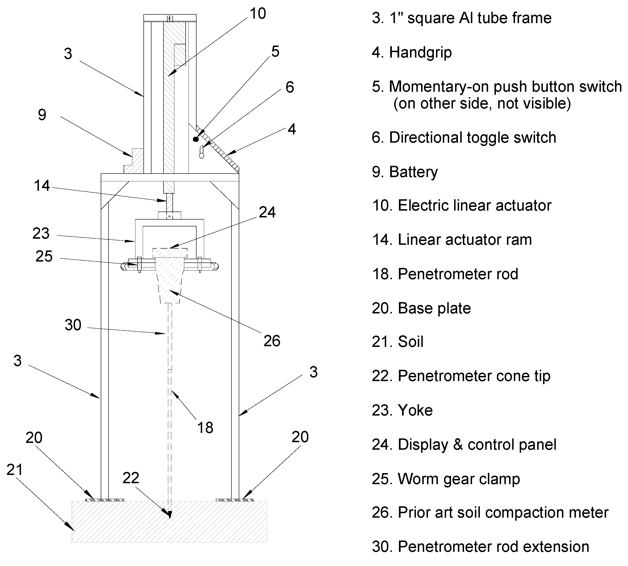
The first prototype, referred to as the bipod, consisted of two legs equipped with base plates on which the operator stood (
Figure 1, #20). These base plates were connected to a lightweight aluminum frame constructed from 2.5 cm square tubing with a 0.16 cm wall thickness (1″ OD, 0.062″ wall). This frame served as the structural platform for all three device embodiments, supporting the penetrometer, linear actuator, and associated components. A commercially available penetrometer (FieldScout™ SC 900 Soil Compaction Meter, Spectrum Technologies, Inc., Aurora, IL, USA) was mounted to a yoke (
Figure 1, #23) using worm-gear clamps (
Figure 1, #25). The yoke allowed full access to the penetrometer’s display and control panel (
Figure 1, #24) so that data collection could be initiated in the standard manner.
To operate the bipod, the user positioned their feet on the base plates (
Figure 1, #20), placed one hand on the handgrip (
Figure 1, #4), set the directional toggle switch to the downward position (
Figure 1, #6), and pressed the momentary-on pushbutton (
Figure 1, #5). The linear actuator (
Figure 1, #10; Model PA-14P, Progressive Automations, Arlington, WA, USA), powered by a 12 V lithium-ion battery (
Figure 1, #9), advanced the probe tip (
Figure 1, #22) into the soil (
Figure 1, #21) at a steady insertion rate. The operator’s static body weight stabilized the base plates, eliminating the need for physical exertion during insertion. Once the desired depth was reached, the toggle switch was moved to the upward position, and the pushbutton was pressed again to retract the probe. Throughout operation, the user remained upright, and the actuator provided insertion and retraction force.
For smaller operators, stability and anchoring force were improved when an assistant placed one foot on one base plate while the operator stood on the other. This configuration effectively doubled the available downward force, ensuring sufficient anchoring even for operators weighing as little as 55 kg. In cases where extremely compacted soil or stones caused the probe to resist penetration, the base plates could momentarily lift from the soil surface. If the operator had both feet on the plates, this could cause a brief loss of balance. To mitigate risk, the push button was intentionally designed as a momentary-contact switch, allowing the operator to instinctively release it and immediately stop probe movement. When two individuals, each placed one foot on a base plate, any upward movement of the frame was less destabilizing.
After completing a measurement, the operator grasped the frame with one hand and carried the 7 kg unit horizontally—with the probe still attached—to the next sampling location.
2.2. Tripod Design and Operation
The bipod prototype was successfully used for many measurements, but an error “!Error-Too Fast!” was often reported on the display even though the plant residue was removed, the soil surface smoothed and the target plate included with the device was placed on the soil surface. This did not occur as frequently as when pushing the probe manually, but it was still an annoyance. The operator’s manual (
https://www.specmeters.com/assets/1/22/6110FS-SC900.pdf, accessed 1 July 2026) specified that the operator’s feet should be placed at least “4 to 6” from the probe tip (10 to 15 cm), and the design of the bipod had the base plates the operator stands on at well beyond that distance. However, a diagram in the operator’s manual shows the field of view of the sensor to be 30° from the shaft. The sensor is 0.71 m (28″) from the soil surface before insertion, so a calculation would suggest that the tangent of 30° *(0.71) = 0.46 m (16″) would place the operator’s feet within the maximum field of view. It was believed at the time that this may be causing the “Too Fast” error as the rated no load speed of the actuator was less than the suggested speed of the probe insertion rate. Spreading the operator’s legs even farther apart would not be practical, so a tripod design was envisioned that would move the ultrasonic depth sensor farther from the operator to prevent any possibility of interference.
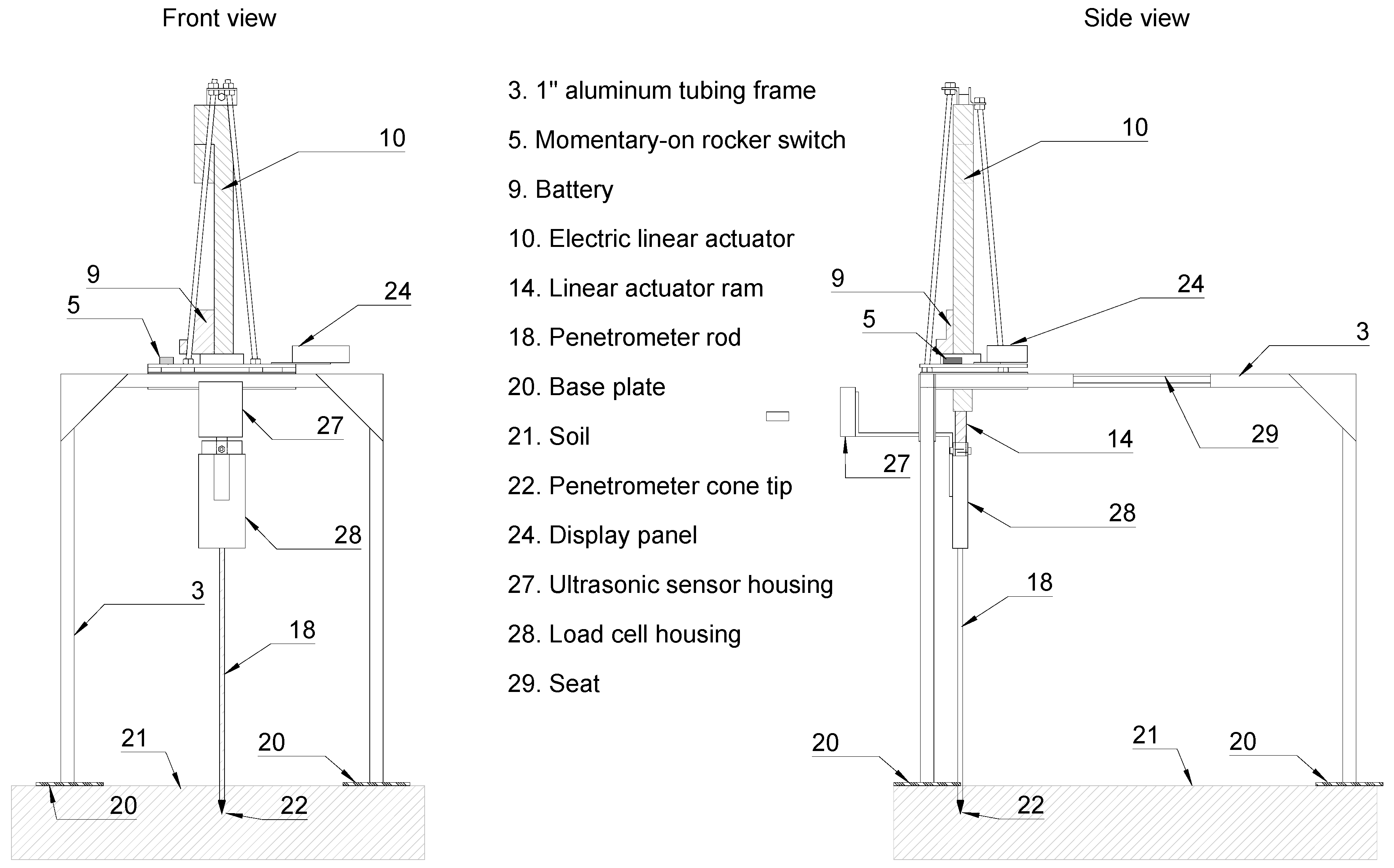
The tripod prototype (
Figure 2) still uses the ultrasonic depth sensor, load cell and control and display panel from the FieldScout™ SC 900 though they have been separated from the original instrument to achieve the desired separation between the ultrasonic depth sensor’s field of view and the operator. The penetrometer rod extension (
Figure 1, #30) has been removed and replaced with a short one, so the seat is at a comfortable height. It is assumed the original device required it so the ultrasonic sensor would not be closer to the soil surface than its minimum detection limit and to allow the operator to insert the probe tip at a more comfortable height. The ultrasonic sensor is fixed at the same height on the tripod relative to the soil surface as on the original device.
2.3. Monopod Conception and Operation
A support frame constructed to use the operator’s static body weight and the linear actuator for the insertion and retraction of the probe also presented an opportunity to replace the ultrasonic depth sensor with a different depth measurement sensor. A frame with a base plate allows the distance of the probe tip from the soil surface to be accurately determined, and then any incremental change in that position can be measured in a number of ways. Some electric linear actuators are available with Hall Effect sensors or potentiometers for determining the distance the ram is extended. A new design was conceived, and a new prototype was built incorporating the ideas of power insertion, static body weight and potentiometer depth measurement. The experience with the bipod demonstrated that most of the body’s weight is most comfortably applied through the use of just one foot on a base plate so that the other foot is on solid ground that will not shift, and the operator will not feel off balance. Experimentation showed that about 70–75% of total body weight could be transferred to one foot with no feeling of being off balance. This weight must be placed as close to the probe shaft as possible to counter the upward force from the probe tip and keep the upright frame from departing from vertical. This is not possible with the prior design in which an ultrasonic sensor is placed directly above the probe shaft. However, by using the potentiometer built into the linear actuator, the close proximity of the operator’s foot is not a problem. In fact, several people can add their weight to the footpad if desired. This is not generally required for measuring soil penetration resistance, but this device can be adapted to take small soil cores or make holes for soil moisture sensors, and those operations may require more force. This new design was called the “monopod”.
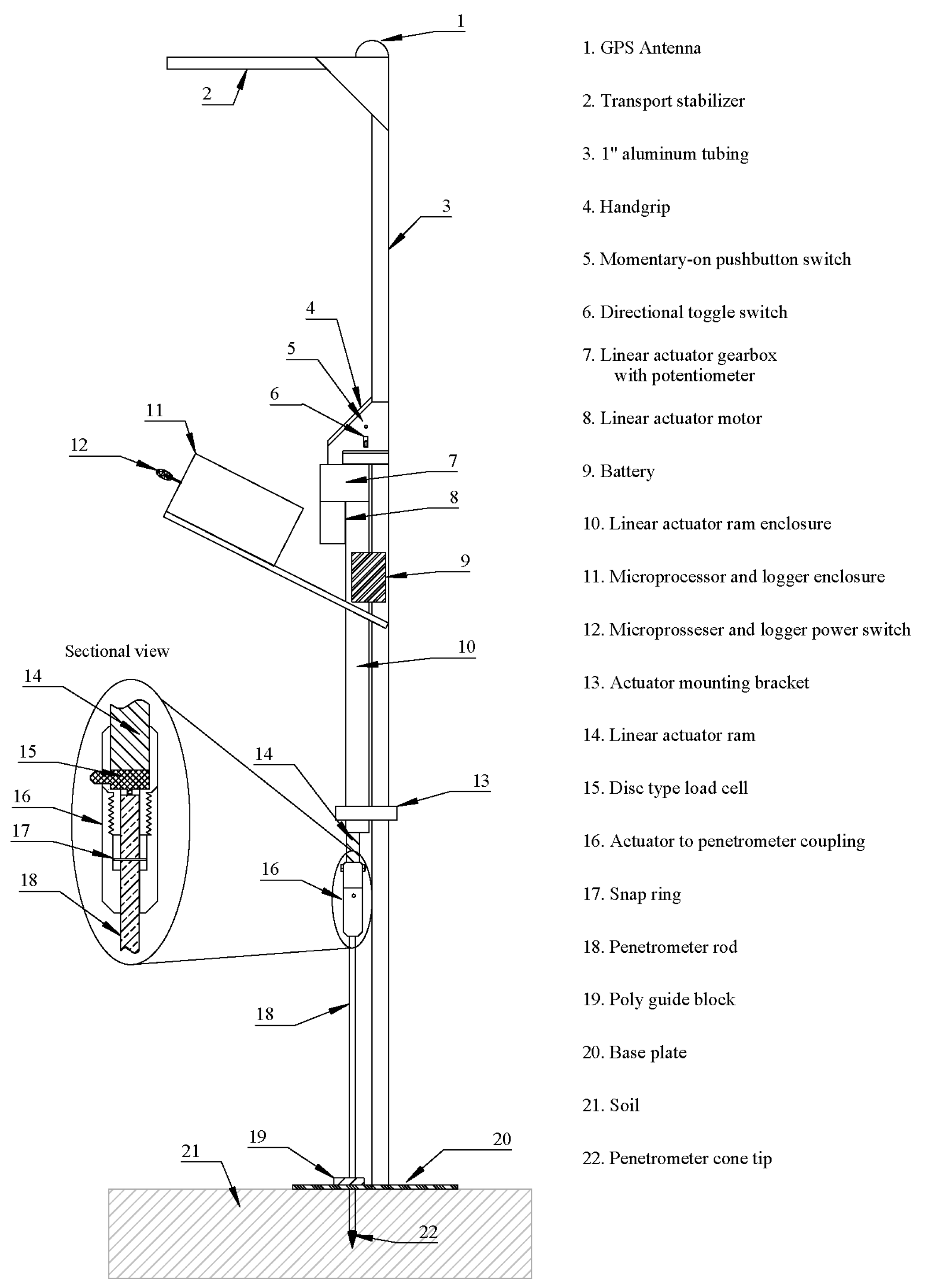
The monopod prototype design only required a single upright frame member (
Figure 3, #3) which resulted in a lighter, more compact unit. The base plate (
Figure 3, #20) was welded to the bottom of the upright frame member. To collect data, the toggle switch (
Figure 3, #12) is flipped to the “on” position. This powers up the components inside the microprocessor and logger enclosure (
Figure 3, #11). The operator places a foot on the base plate and leans toward the frame member transferring most of the body weight to the base plate. The directional control toggle switch (
Figure 3, #6 is placed in the down position and the momentary-on pushbutton switch (
Figure 3, #5) is pressed to allow power from the battery (
Figure 3, #9) to flow to the linear actuator motor (
Figure 3, #8). The linear actuator ram (
Figure 3, # 14) forces the probe into the soil. Power for the linear actuator was supplied by a 12 volt 1.5 or 6 A h lithium-ion power tool battery (
Figure 3, #9). As the penetrometer cone tip (
Figure 3, #22) moves through the soil, the depth, pressure, record count and battery voltage are displayed on the liquid crystal display mounted in the microprocessor and logger enclosure. When the desired maximum depth is obtained, the operator flips the directional control toggle switch to the “up” position and presses the momentary-on switch and the probe is retracted. When the probe begins to retract, the data for all the records collected for that sample location are written to the SD card in the data logger.
3. Engineering Details
The frames for all of these units were constructed from 25 mm square tubing with a wall thickness of 1.6 mm. All of the triangular corner braces were cut from 1.6 mm aluminum sheet. The base plates were made from 6.3 mm thick aluminum. The weights for the bipod (including the FS 900), Plainfield, IL, USA, tripod and monopod respectively were 6.98, 6.56 and 5.34 kg. These weights were with the 1.5 A h 12v battery (Milwaukee M12, Milwaukee Tool, Brookfield WI, USA). A larger 6 A h battery was used at times, and it increased these weights by 0.56 kg. The larger battery would allow over 80 samples to be taken to a 46 cm depth in a field that averaged 1.8 MPa. The frame height on the monopod is 1.8 m, so the optional GPS is unobstructed by the operator. If a GPS is not used, the frame height could be reduced to 1.2 m and still obtain a 46 cm sample depth. The transport stabilizer (
Figure 3, #2) was added to keep the monopod flat in the back of a vehicle during transport. The long axis of the base plate (
Figure 3, #20) is parallel to the transport stabilizer. Without it, the plastic microprocessor and logger enclosure (
Figure 3, # 11) would have to support the weight of the unit during transport.
The microprocessor is an Arduino® Uno, (Arduino Official Store|Boards Shields Kits Accessories—Arduino Online Shop, Lakewood, NJ, USA). The data logger is a circuit board with an SD card slot that is called a shield because it plugs into the headers on the microprocessor (Adafruit Data Logger Shield, Overview|Adafruit Data Logger Shield|Adafruit Learning System). The SD card can store several million records that are in a csv format. The liquid crystal display is a four-line by 20-character display. Power for the microprocessor is supplied by a separate nine-volt battery located in the microprocessor and logger enclosure to prevent the electrical noise generated by the linear actuator motor from affecting the microprocessor.
Pressure is measured by a disk type load cell (sometimes called a button strain gauge) (
Figure 3, # 15). A TAS606 200 kg model (SparkFun Electronics
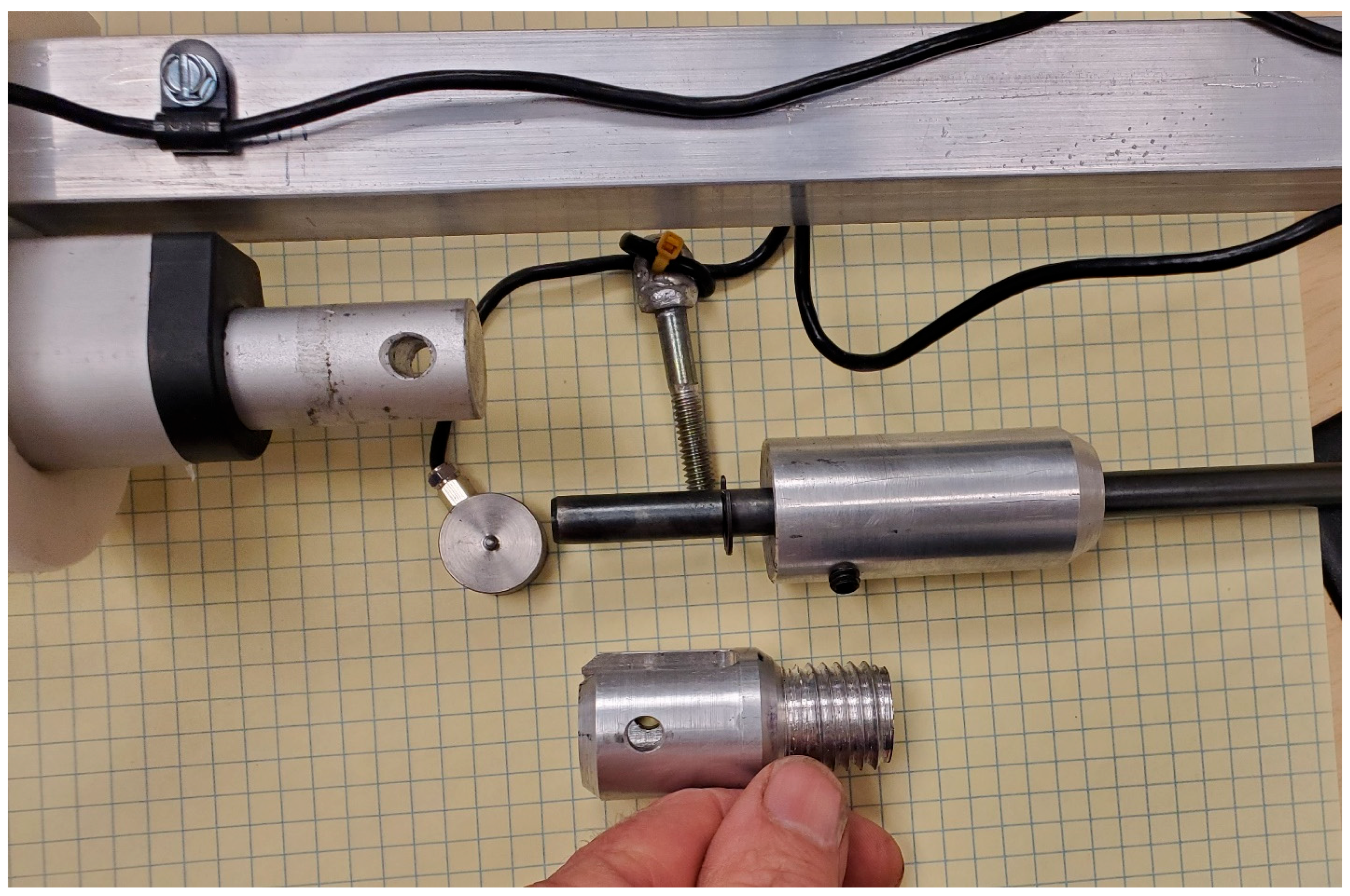
®6333 Dry Creek Parkway, Niwot, CO, USA) was used in the prototype. These units are available in nine capacities from 5 to 500 kg in the same 20 mm × 11 mm form factor, so it is a simple matter to change them out if more accuracy or greater capacity is desired. The combined error of the load cells in this series is ±0.05% of the full-scale output and a repeatability of ±0.2%, so a load cell with a smaller full-scale output will provide greater accuracy as long as the capacity is sufficient. Combined error is the term given to the combination of non-linearity and hysteresis errors. The load cell is easily changed by unscrewing the actuator to penetrometer coupling (
Figure 3, #16 and
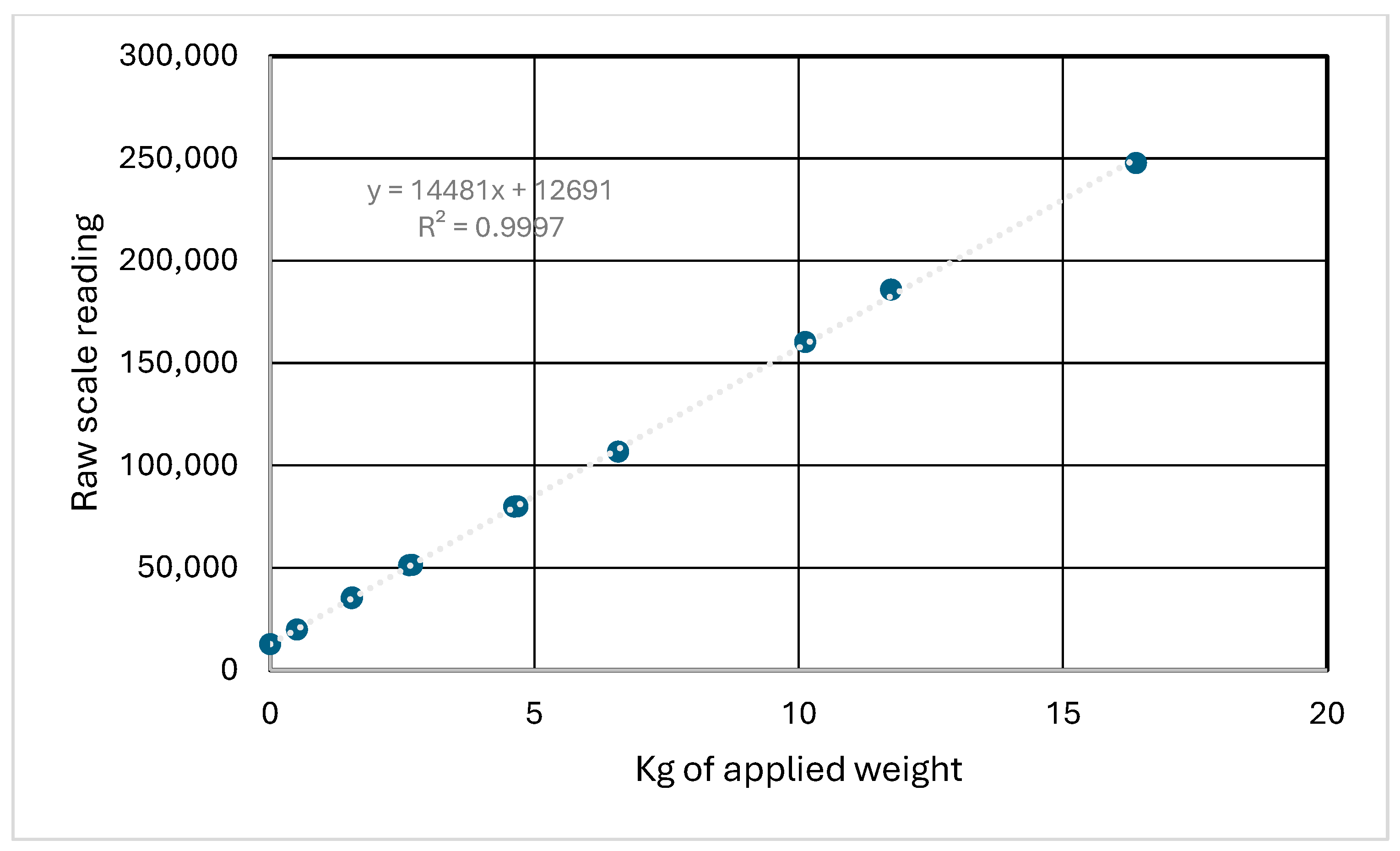
Figure 4). The load cell was calibrated by removing the cone tip and replacing it with a hex head bolt. The assembled monopod penetrometer was placed on an accurate small platform scale without the penetrometer shaft touching the scale and the raw scale output was recorded. The penetrometer shaft was then extended so the base plate was lifted off the scale platform. To achieve a starting weight of less than the weight of the monopod, a floor hoist with a rubber strap lifted up on the frame. Weights were added to the base plate (
Figure 3, #20). As each weight was added, the raw scale output displayed on the monopod LCD and the platform scale weight were recorded. The calibration equation was determined from these values and then incorporated into the microprocessor’s software program. The calibration results are shown in
Figure 5.
There are electric linear actuators that have built in force sensors, and these were considered. However, the ones available at the time of construction were more than double the weight of the linear actuator that was used for this prototype. Keeping the weight of this hand carried unit as low as possible was a priority, so the units with the integrated force sensor were ruled out for now but it is expected there may be units in the future that would be acceptable.
The small analog signals from the load cell were fed to a breakout board that has an analog to digital converter, amplifier and I2C output (SparkFun Qwiic Scale—NAU7804, SparkFun Electronics®6333 Dry Creek Parkway, Niwot, CO, USA) that processes the signal from the load cell so the microprocessor can interpret it.
The capacity of both the linear actuator and the load cell were calculated based on the recommendations set forth in ASAE S313.3 FEB1999 (R2018) [
20]. Quoting from that reference, “The measuring device of hand-operated units should have a cone index capacity of approximately 2 MPa (290 psi) for the 323 mm
2 (0.5 in
2) base area penetrometers and not exceed 5 MPa (725 psi) for the 129 mm
2 (0.2 in
2) base area penetrometers in order to be suitable for most agricultural soil conditions.” To determine the force required on the penetrometer shaft:
The calculations above are for the maximum capacity. For the average recommendation of 2 MPa, the same calculation results in a force of 259 Newtons.
The speed of insertion recommended in the ASAE EP542.1 standard is approximately 30 mm/s [
19].
The linear actuator selected based on these criteria was model PA-14P-18-50, (Progressive Automations, Arlington, WA, USA). The no-load speed of this actuator is 29 mm/s with a full-rated load speed of 20 mm/s at 222 Newtons. It will achieve a maximum static force of 445 Newtons.
4. Results and Discussion
All three of the embodiments met the objectives of eliminating stress and strain on the operator. It was much easier to obtain the desired depth of 46 cm with the mechanically assisted units than with the hand push probe. One surprising discovery was that the “Too Fast” error occurred with both the bipod and tripod units even though the rated no load speed of the actuator was less than the suggested speed of the probe insertion rate of 30 mm/s. Even with the three-phase controller on the tripod unit which held the speed of the actuator within a tighter range than the simpler straight DC actuator on the bipod the error occasionally occurred, though less frequently than when the probe was manually operated. The speed of insertion was checked with a stopwatch and reduced to about 20 mm/s but still that error would occasionally occur and require restarting the sample. It was observed that the error message was often seen when there was a sudden change in soil density or it may be related to the ultrasonic sensor reporting a value at the lower side of its accuracy range and then on the next reading it reports a value at the high side. This would calculate a larger depth interval than what was actually covered in a given amount of time and thus may have generated a speed error. The monopod never had this problem.
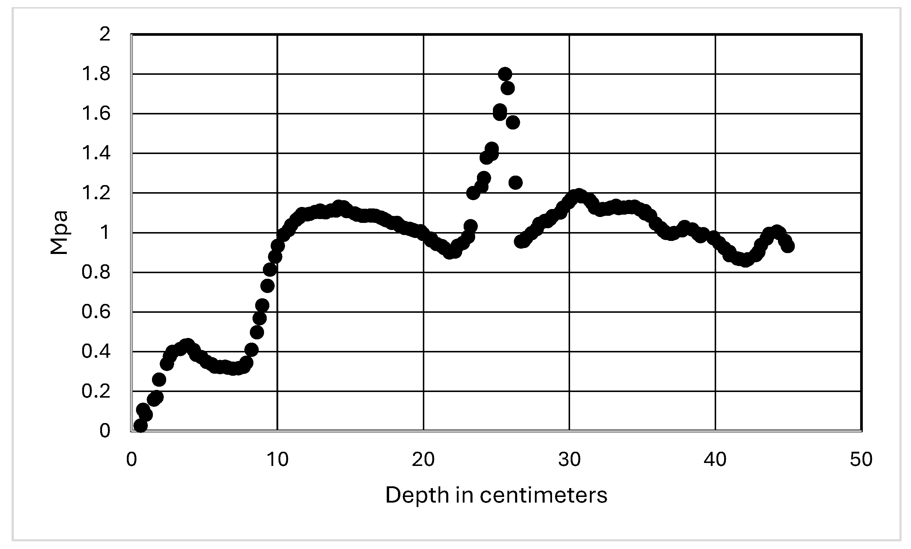
An example of recording at maximum resolution is shown in
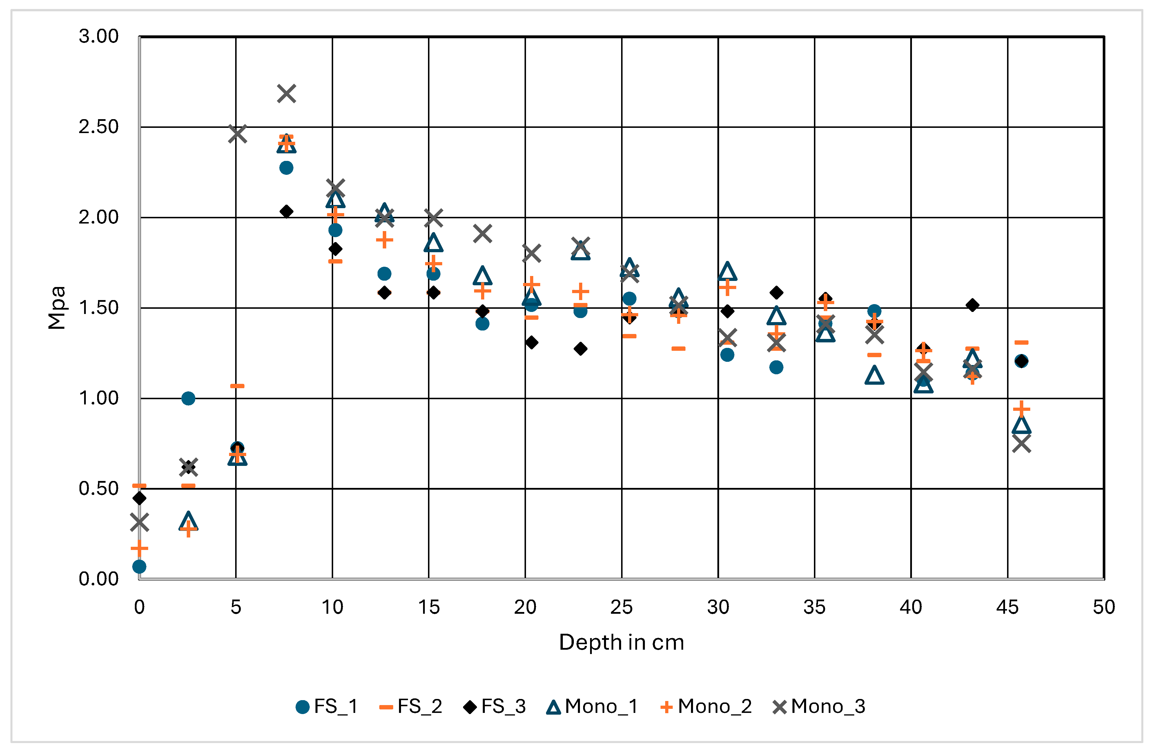
Figure 6, where a small stone is encountered at 22 cm. While the data presented for comparison of the monopod with the commercially available unit are shown at larger increments of 25 mm (
Figure 7), the monopod has the capability to capture a reading every 100 to 150 ms, or about every 3 to 5 mm. This significant increase in precision and resolution may be of great value to researchers.
Evaluating cone index data presents challenges due to the variability of the soil as well as tillage and traffic patterns [
3]. A location was selected that was a non-crop area to minimize the variability. Cone index values recorded at a given location using the monopod were compared to reference cone index values recorded 10 cm away using the manually operated FieldScout SC900, Plainfield, IL, USA. This process was repeated at randomly selected locations.
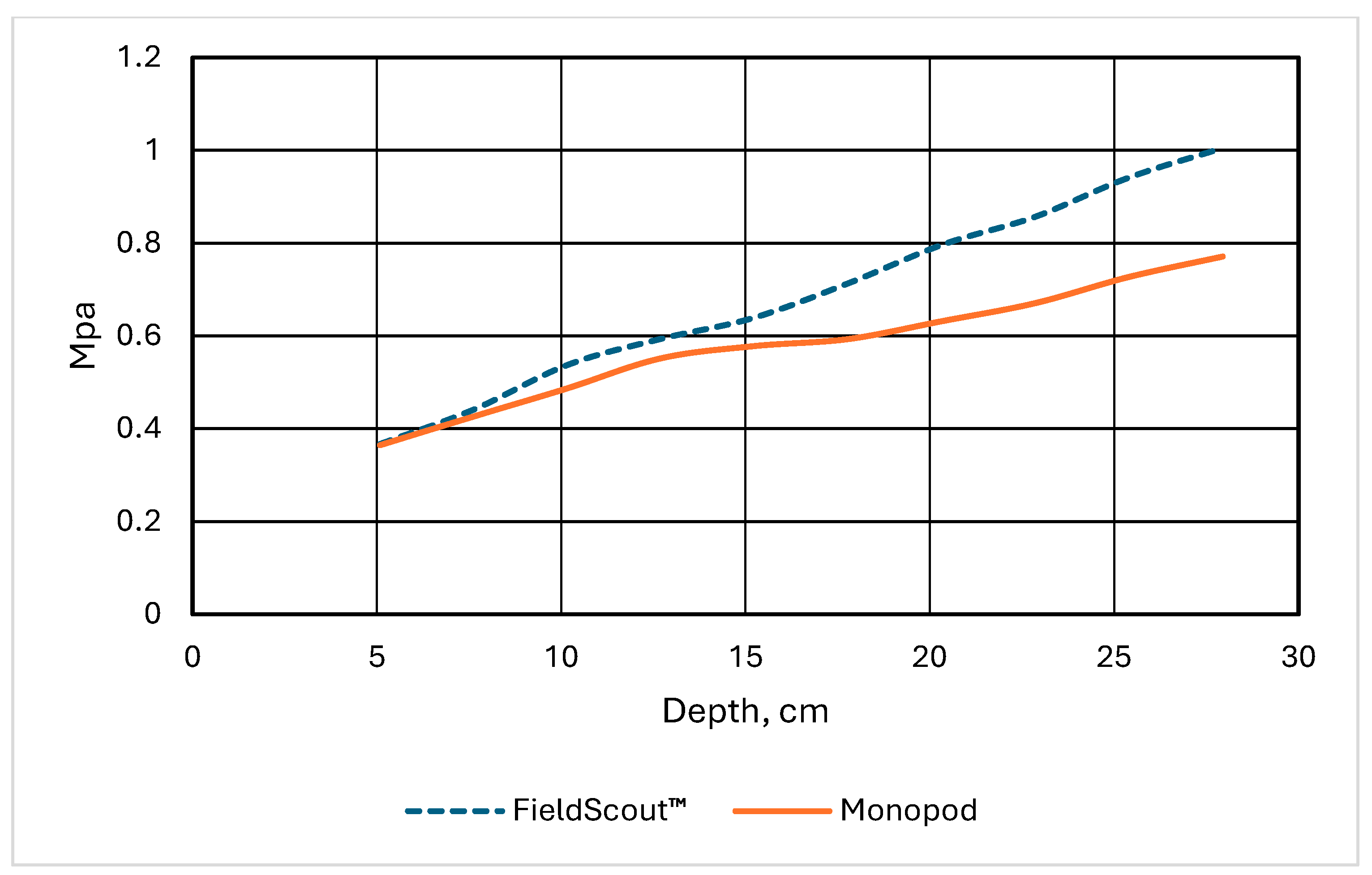
Figure 7 summarizes three pairs of adjacent samples at 19 depths. The legend entries with the “FS_” prefix are the records from the FieldScout, and the “Mono_” entries are the records from the monopod. The average of the variance for each set of readings at each depth shown in the chart from 8 to 46 cm is 0.0152 for the FieldScout and 0.0082 for the monopod, suggesting that the monopod may be more accurate than the FieldScout.
Comparing these two devices is somewhat difficult for a number of reasons. One reason of course is the inherent variability [
8,
17] of the alluvial soils in the area with many small stones present (
Figure 6). Another is that the FieldScout™ only has a pressure resolution of 0.034 MPa (5 psi) with a stated accuracy of ± 0.103 MPa (±15 psi) and a depth resolution of 2.5 cm (1 in) with a depth accuracy of ±1.25 cm (±0.5 in). The monopod has a pressure resolution of ±0.0008 MPa (0.1 psi) and a load cell accuracy of ±0.038 MPa (5.5 psi) with the 200 kg load cell. As noted above, using a 50 kg load cell would reduce the error by a factor of four. It is duly noted that this is the accuracy of the load cell and not the assembled unit. It is unknown exactly how much the friction between the penetrometer rod (
Figure 3, #18) and the actuator to penetrometer coupling (
Figure 3, #16) affects accuracy. The rod moves freely through the bored hole in the coupling and is aligned directly below the actuator ram (
Figure 3, #14) at the start of each hole by the poly guide block (
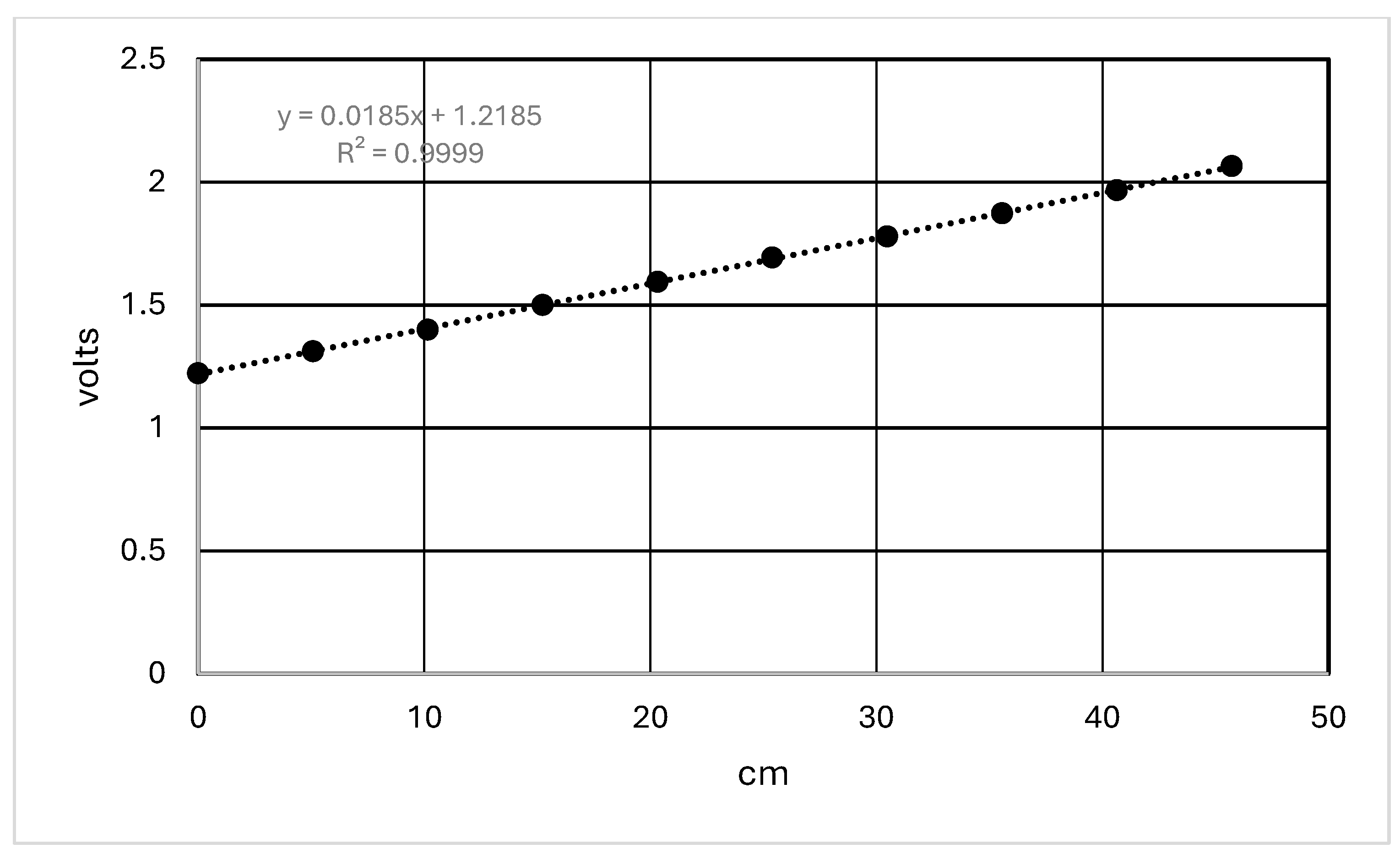
Figure 3, #19) to minimize any side thrust. When the calibration was done for the load cell it was installed in the monopod and the rod was extended as it would be in the field. The complete unit was on the scale so the friction should have been accounted for. The depth resolution of the monopod is ±1 mm (0.04 in). This was determined by attempting readings at increasingly smaller increments until the processor could not complete the operations needed to read the potentiometer, the load cell, perform the required calculations and write the data to the logger’s memory card. The linear actuator’s potentiometer accuracy is not stated in the manufacturer’s data sheet. The extension of the actuator ram was measured with a steel scale and then the voltage was recorded at each 5 cm (2-in) increment. From the results shown in
Figure 8, it was concluded that accuracy is better than the resolution used.
The FieldScout™ pressure calibration check was performed according to the instruction manual. The procedure uses the weight of the meter as a single point calibration. The meter is placed on a hard surface and after a count down the meter should read between 0.035 and 0.070 MPa (5–10 psi), which it did. Values from 57 paired measurements from the FieldScout™ and the monopod were compared with a
t-test and showed a significant difference (
p < 0.05) between the two instruments. To determine the cause of the difference a more accurate means of comparison of the pressure was desired to evaluate the validity of the monopod and make sure the calculations in the software were correct. Comparisons in the field indicated that the instruments were close but with the variability of the soils even probing 10 cm apart with the same instrument would yield different results (
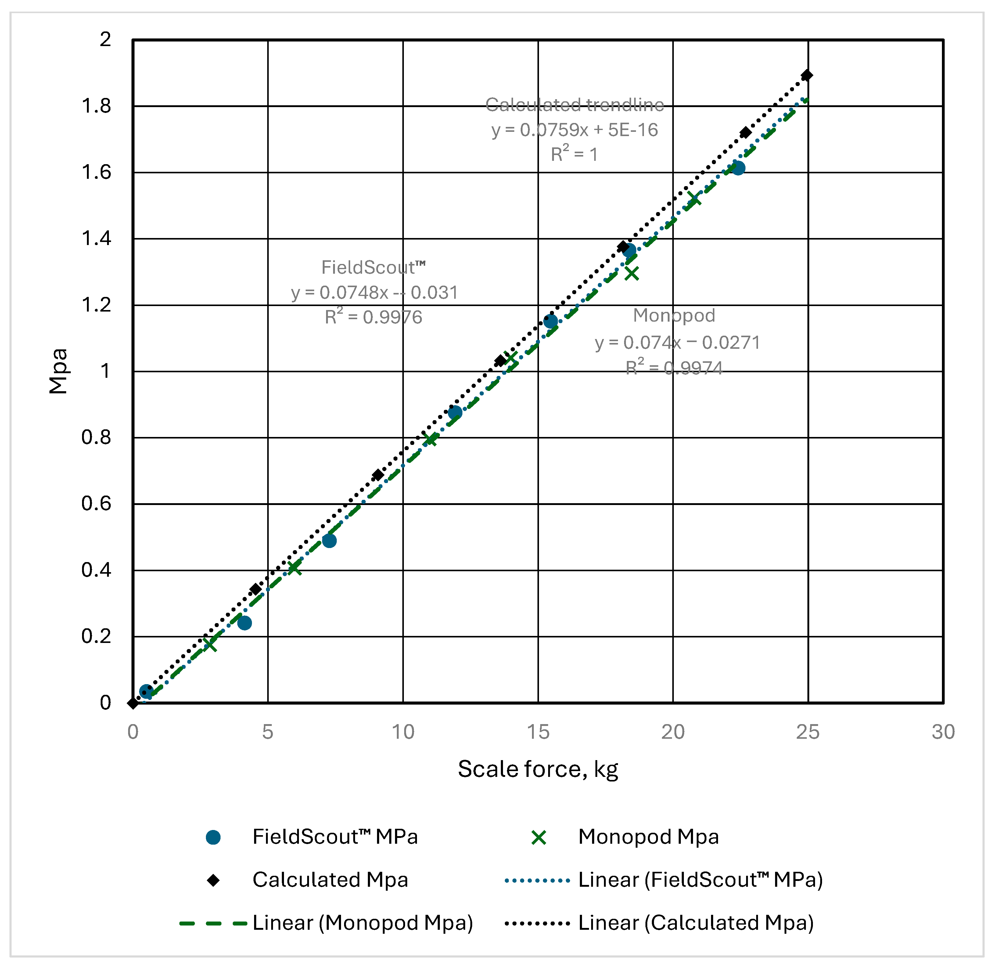
Figure 7). The FieldScout™ refreshes the pressure reading only if it is recording a change in depth so a method had to be devised that would allow it to be tested on a scale. The cone tip was replaced with a bolt about 5 cm long. The head of the bolt rested on the calibration scale platform. The purpose of the bolt was two-fold. It protected the penetrometer tip and scale platform from damage and allowed the target plate to be suspended above the scale so as to not influence the calibration weight and still be at the same relative distance from the ultrasonic sensor that it would be if the tip was on the shaft and it was placed on the soil surface as it would be for normal operation. A light pipe was fastened to a corner of the target plate that allowed the operator to raise the target plate to simulate the probe moving into the soil while being able to monitor the readings on the instrument. To add weight, one end of a piece of square tubing was clamped to the FieldScout™ handles and the other end secured to a nearby workbench. Weights were added to the horizontal piece of square tubing and the force on the scale and the cone index value were recorded for each additional weight. The process was repeated with the monopod, except the target plate was not needed. The two instruments gave virtually identical results as shown in
Figure 9, and both compared very well to the calculated cone index value trendline. The scale breakout board for the load cell used in the monopod has the capability to take measurements at up to a 400 kHz rate and the software library has a function to average readings. As tested, the monopod only took a single reading for each depth and did not take advantage of this capability, but it will be incorporated in the future and that will most likely improve the accuracy even more.
After concluding that both units returned identical results on the scale, further analysis of the 57 paired samples showed no difference using a paired sample T-test between the sample means (
p = 0.89) at depths less than 12 cm but the combined depths greater than 12 cm had a significant difference (
p = 0.044). Analysis of a larger dataset of 159 paired samples showed the same trend with no difference (
p = 0.564) at the shallowest three depths and the greatest separation between means (
p = 0.011) occurring at the deepest two depths. Barone and Faugno [
28] compared a manual push penetrometer fitted to a mechanical soil probe to the same unit pushed in by hand. They also found a significant difference at deeper depths and offered an explanation for the differences observed between deeper and shallower depths. Quoting from that reference [
28]; “In the “Manual” mode, as PR increases, it becomes difficult to maintain a constant speed and a perpendicular position to the soil during rod insertion. This raises the friction between soil and rod, since the movement is not constant and in the same direction, causing soil-rod contact on the wall of the hole formed by the insertion. When the speed is constant and the equipment is placed perpendicularly to the soil and without oscillation, the soil-rod contact is minimized, reducing variability in PR data.” Others have recognized the effect of friction on the rod [
16,
29,
30] with some incorporating the use of a sleeve on the penetrometer shaft above the cone tip to minimize the effect [
16,
30].
Figure 10 shows the comparison of the two instruments by depth from a different data set. Sixty different locations were sampled over 3 ha. The penetrometer measurements were about 15 cm apart at each location. Though the FieldScout™ was used by an experienced operator, the data seem to agree with Herrick and Jones [
21] that as the manually pushed rod is forced deeper the soil to rod friction increases.
5. Cost Considerations
The cost of the materials used in the construction of the monopod is shown in
Table 1. The prototype was built in a farm shop with common tools. The only specialized mechanical skills required were for welding the base plate to the square tubing with an aluminum welder and machining the actuator to penetrometer coupling with a metal lathe. Basic wiring and soldering skills were required to assemble the electronic components.
The open-source Arduino Software Integrated Development Environment (IDE) was used to program the Arduino so there is no material cost for that. It did take a fair amount of time to develop and could still be refined for a user’s particular needs, but like most softwares it can easily be transferred to thousands of new units with little additional cost involved. An optional GPS available from Adafruit.com with an external antenna and 10 Hz update frequency is available for $48.90 USD. It is compatible with the Arduino Uno and was tested separately but the GPS code has not yet been incorporated into the monopod data logger software. The Arduino Uno is at 75% memory capacity with the existing monopod code, so it may need to be upgraded to a more capable microprocessor such as the Arduino Mega if the GPS is used. The cost of the Mega is $34.95 USD.
The total cost of materials for the monopod was about $570 USD. The FieldScout™ SC 900 Soil Compaction Meter, Spectrum Technologies, Inc. Aurora, IL, USA costs $1950 USD. The Rimik CP4011, Rimik, Toowoomba, Australia, also a manual-push penetrometer with GPS, is $6600 USD. A GPS could be added to the monopod for about $75 USD material cost. The Eijkelkamp Penetrologger Kit, which is also a manual push-penetrometer, from Eiijkelkamp, Giesbeek, the Netherlands, is $7400.45 USD.
6. Conclusions
The mechanically assisted soil penetrometer designs that use the operator’s static body weight to anchor the device greatly reduced the chance of repetitive use injuries. All three designs allowed the collection of deep samples with much less effort and strain than the manual push probe. Errors associated with the penetrometer rod contacting the side of the hole were reduced. The portability of the penetrometer was maintained. The monopod design that incorporated the potentiometer for depth measurement eliminated the problems associated with the ultrasonic sensor in windy or high surface roughness conditions and provided greater depth measurement accuracy than the currently available hand-carried penetrometers. It can be used in strip-tilled fields without interference from the biomass in the untilled strips. The bipod and tripod designs reduced and the monopod eliminated the frustrating errors associated with an incorrect insertion rate. The monopod design would be seen as the preferred embodiment of the hand carried mechanically assisted soil penetrometer.
7. Patents
U.S. Patent No. 12,455,272 was issued on 28 October 2025.
The sole inventor, engineer and fabricator was William M. Iversen.
The Assignee is the United States of America, as represented by the Secretary of Agriculture, Washington, DC (USA).
Author Contributions
Conceptualization, visualization, software development and operational validation, W.M.I.; evaluation methodology, W.M.I. and J.D.J.; formal analysis, investigation, W.M.I., J.D.J. and W.B.S.; resources, W.B.S., W.M.I. and J.D.J.; data curation, W.M.I. and W.B.S.; manuscript preparation, W.M.I., W.B.S. and J.D.J.; manuscript review and editing, W.B.S. and J.D.J.; project administration, W.B.S. All authors have read and agreed to the published version of the manuscript.
Funding
This research received no external funding.
Institutional Review Board Statement
Not applicable.
Informed Consent Statement
Not applicable.
Data Availability Statement
A non-disclosure agreement with Spectrum Technologies, Inc., Aurora, IL, USA, was signed on 5 December 2023 and the one-year agreement was renewed a year later. No data other than those in this manuscript are publicly available.
Conflicts of Interest
The authors declare no conflicts of interest.
References
- Shah, A.N.; Tanveer, M.; Shahzad, B.; Yang, G.; Fahad, S.; Ali, S.; Bukhari, M.A.; Tung, S.A.; Hafeez, A.; Souliyanonh, B. Soil compaction effects on soil health and crop productivity: An overview. Environ. Sci. Pollut. Res. 2017, 24, 10056–10067. [Google Scholar] [CrossRef] [Scilit]
- Bengough, A.G.; McKenzie, B.M.; Hallett, P.D.; Valentine, T.A. Root-soil interactions of germinating wheat seedlings under a wide range of moisture and compaction conditions. Plant Soil 2011, 347, 327–340. [Google Scholar]
- Campbell, D.J.; O’Sullivan, M.F. The cone penetrometer in relation to trafficability, tillage, and plant growth. In Soil Analysis: Physical Methods; Smith, K.A., Mullins, C.E., Eds.; Marcel Dekker: New York, NY, USA, 1991; pp. 273–311. [Google Scholar]
- Bengough, A.G.; Mullins, C.E. Mechanical impedance to root growth: A review of experimental techniques and root growth responses. J. Soil Sci. 1990, 41, 341–358. [Google Scholar] [CrossRef] [Scilit]
- Suzuki, L.E.; Reichert, J.M.; Reinert, D.J. Degree of compactness, soil physical properties and yield of soybean in six soils under no-tillage. Soil Res. 2013, 51, 311–321. [Google Scholar]
- Nevens, F.; Reheul, D. The consequences of wheel-induced soil compaction and subsoiling for silage maize on a sandy loam soil in Belgium. Soil Tillage Res. 2003, 70, 175–184. [Google Scholar] [CrossRef] [Scilit]
- Shaheb, M.R.; Venkatesh, R.; Shearer, S.A. A review on the effect of soil compaction and its management for sustainable crop production. J. Biosyst. Eng. 2021, 46, 417–439. [Google Scholar] [CrossRef] [Scilit]
- De Cauwer, V.; Cool, S.; Willekens, A.; Temmerman, S.; Nuyttens, D.; D’ Hose, T.; Pieters, J.; Leroux, S. Development and in-field validation of an autonomous soil mechanical resistance sensor. Sensors 2025, 25, 1919. [Google Scholar] [CrossRef] [Scilit] [PubMed]
- Lowery, B.; Morrison, J.E. Soil penetrometers and penetrability. In Methods of Soil Analysis; Dane, J.H., Topp, G.C., Eds.; Soil Science Society of America: Madison, WI, USA, 2002; pp. 363–388. [Google Scholar]
- Bengough, A.G.; Campbell, D.J.; O’Sullivan, M.F. Penetrometer techniques in relation to soil compaction and root growth. In Soil and Environmental Analysis: Physical Methods, Revised, and Expanded, 2nd ed.; Smith, K.A., Ed.; CRC Press: Boca Raton, FL, USA, 2000; p. 660. [Google Scholar] [CrossRef] [Scilit]
- Wesley, L.D.; Dobie, M.J. Early development of the Dutch cone penetrometer test. Proc. Inst. Civ. Eng.-Eng. Hist. Heritage. 2022, 175, 145–152. [Google Scholar] [CrossRef] [Scilit]
- Freitag, D.R. Penetration Tests for Soil Measurements; Waterways Experiment Station: Vicksburg, MS, USA, 1968. [Google Scholar]
- Gill, W.R. Influence of compaction hardening of soil on penetration resistance. Trans. ASAE 1968, 11, 741–745. [Google Scholar] [CrossRef] [Scilit]
- Massarsch, K.R. Cone penetration testing–A historic perspective. Proc. CPT 2014, 14, 97–134. [Google Scholar]
- Hemmat, A.; Adamchuk, V.I. Sensor systems for measuring soil compaction: Review and analysis. Comput. Electron. Agric. 2008, 63, 89–103. [Google Scholar] [CrossRef] [Scilit]
- Chi, L.; Tessier, S.A. Portable micro-penetrometer for measuring seed row compaction. Soil Tillage Res. 1995, 34, 27–39. [Google Scholar] [CrossRef] [Scilit]
- Sudduth, K.; Chung, S.O.; Andrade-Sanchez, P.; Upadhyaya, S.D. Field comparison of two prototype soil strength profile sensors. Comput. Electron. Agric. 2008, 61, 20–31. [Google Scholar] [CrossRef] [Scilit]
- Scholz, C.; Moeller, K.; Ruckelshausen, A.; Hinck, S.; Göttinger, M. Automatic soil penetrometer measurements and GIS based documentation with the autonomous field robot platform bonirob. In Proceedings of the 12th International Conference of Precision Agriculture, 20–23 July 2014; International Society of Precision Agriculture (ISPA): Monticello, IL, USA, 2014. [Google Scholar]
- ASAE EP542.1; Procedures for Using and Reporting Data Obtained with the Soil Cone Penetrometer. ASAE: St. Joseph, MI, USA, 2019.
- ASABE S313.3; Soil Cone Penetrometer. American Society of Agricultural and Biological Engineers: St. Joseph, MI, USA, 2017.
- Herrick, J.E.; Jones, T.L. A dynamic cone penetrometer for measuring soil penetration resistance. Soil Sci. Soc. Am. J. 2002, 66, 1320–1324. [Google Scholar] [CrossRef] [Scilit]
- Mahore, V.; Soni, P.; Patidar, P.; Machavaram, R. An IoT-enabled penetrometer with constant-rate penetration for accurate measurement of soil cone index. Cogent Eng. 2024, 11, 2372088. [Google Scholar]
- Moacir, T.; de Moraes, M.T.; da Silva, V.R.; Zwirtes, A.L.; Carlesso, R. Use of penetrometers in agriculture: A review. Eng. Agrícola 2014, 34, 179–193. [Google Scholar] [CrossRef] [Scilit]
- Fountas, S.; Paraforos, D.; Cavalarisb, C.; Karamoutisb, C.A.; Gemtos, T.A.; Abu-Khalaf, N.; Tagarakis, A. A five-point penetrometer with GPS for measuring soil compaction variability. Comput. Electron. Agric. 2013, 96, 109–116. [Google Scholar] [CrossRef] [Scilit]
- Nisha, K.; Upadhyay, G.; Patel, B.; Choudhary, S.; Rani, V. A tractor hydraulic assisted embedded microprocessor-based penetrometer for soil compaction measurement. J. Terramech. 2023, 110, 1–12. [Google Scholar] [CrossRef] [Scilit]
- Gwiżdż, M.; Kotras, A. Influence of ultrasonic wind sensor position on measurement accuracy under full-scale conditions. Sensors 2020, 20, 5640. [Google Scholar] [CrossRef] [Scilit] [PubMed]
- Rudyk, A.; Semenov, A.; Baraban, S.; Semenova, O.; Kulakov, P.; Kustovskyj, O.; Brych, L. Influence of environmental factors on the accuracy of ultrasonic rangefinders for mobile robots. Electronics 2025, 14, 1393. [Google Scholar] [CrossRef] [Scilit]
- Barone, L.; Faugno, S. Penetration tests for measurement of soil strength: Assessment of the contribution of shaft friction. J. Agric. Eng. Res. 1996, 64, 103–108. [Google Scholar] [CrossRef] [Scilit]
- Mome Filho, E.A.; Silva, A.; Figueiredo, G.; Gimenes, F.; Vitti, A. Compared performance of penetrometers and effect of soil water content on penetration resistance measurements. Rev. Bras. Ciência Solo 2014, 38, 744–754. [Google Scholar] [CrossRef] [Scilit]
- Schmittmann, O.; Lammers, P.S. Assessing Subsoil Conditions with an ASABE Conform Vertical Penetrometer—Development and Evaluation. Sensors 2023, 23, 1306. [Google Scholar] [CrossRef] [Scilit] [PubMed]
| Disclaimer/Publisher’s Note: The statements, opinions and data contained in all publications are solely those of the individual author(s) and contributor(s) and not of MDPI and/or the editor(s). MDPI and/or the editor(s) disclaim responsibility for any injury to people or property resulting from any ideas, methods, instructions or products referred to in the content. |