Article

Service-Level Interoperability for Distributed Co-Simulation of Heterogeneous Building Performance Models


by
Abbas Raad
1,* and
Benoit Delinchant
2
1
EPF Engineering School, 94230 Cachan, France
2
G2Elab, Université Grenoble Alpes, CNRS, Grenoble INP, 38000 Grenoble, France
*
Author to whom correspondence should be addressed.
Appl. Sci. 2026, 16(13), 6755; https://doi.org/10.3390/app16136755 (registering DOI)
Submission received: 15 May 2026 / Revised: 15 June 2026 / Accepted: 1 July 2026 / Published: 6 July 2026

Featured Application

The proposed service-oriented interoperability framework enables the integration of heterogeneous building simulation services within distributed co-simulation workflows for early-stage building design. The approach is particularly suited to situations where independently developed tools must interact without direct model coupling or a unified simulation environment. The framework is also designed to facilitate future integration of optimization and decision-support processes through autonomous service interactions.

Abstract

Interoperability remains a central issue in multi-performance building simulation, where heterogeneous domain-specific tools must be combined despite differences in modeling formalisms, numerical solvers, and execution schemes. Existing approaches, including data exchange standards and component-based frameworks such as the Functional Mock-up Interface (FMI), address specific levels of interoperability but often require model-level access, component wrapping, Functional Mock-up Unit (FMU) packaging, or framework-specific integration. This paper examines service-level interoperability, where domain-specific simulation tools are exposed as autonomous web services coordinated through an external orchestration mechanism. A structured, JSON-based Pivot DataSet (PDS) organizes data exchange between services, while coupling strategies are implemented at the orchestration level to manage interactions without accessing internal model structures. The approach is evaluated using a classroom case study from the Agence Nationale de la Recherche (ANR) COSIMPHI research project, focusing on communication overhead, synchronization constraints, and coupling behavior in distributed co-simulation. Under the investigated weak-coupling conditions, the waveform relaxation method (WRM) reduces synchronization iterations by 144× over one day and by approximately 3319× over one month compared with minute-by-minute sequential chaining. These results, obtained under weak thermal–acoustic coupling conditions, highlight the relevance of service-level interoperability and orchestration-level coupling for distributed building-performance simulation workflows involving independently developed domain tools. Their generalization to stronger coupling regimes, however, remains a direction for future work.

1. Introduction

The analysis of building performance increasingly relies on simulation-based methods to address multiple, often competing performance criteria, including energy efficiency, thermal comfort, acoustic quality, lighting conditions, and environmental impact [1,2]. These criteria are typically evaluated using specialized domain-specific simulation tools developed within distinct disciplinary communities. While such tools are mature individually, their combined use remains challenging when interactions between subsystems must be represented within a coherent simulation workflow.
The emergence of Digital Twin approaches in building performance assessment [3,4] has reinforced the need for distributed and interoperable simulation architectures, where heterogeneous domain models must be coupled dynamically over the lifecycle of a building. In such contexts, simulation services are expected to operate continuously across heterogeneous computational environments while exchanging dynamic information in near real time. Service-oriented architectures are increasingly recognized as an enabling layer for Digital Twin frameworks because they support modularity, tool autonomy, distributed execution, and flexible integration of heterogeneous simulation services. However, the implications of such architectures on co-simulation coupling strategies and communication overhead remain insufficiently explored in building simulation workflows.
A central difficulty lies in the heterogeneity of simulation models and tools used in building performance simulation. Models differ in physical assumptions, mathematical formalisms, spatial and temporal resolutions, and numerical solvers [5,6,7]. These differences complicate model integration and coupling, particularly when multiple simulation tools must interact dynamically. Such limitations are especially critical during early design or exploratory analysis stages, where simulation workflows evolve iteratively while available information remains incomplete [8,9].
At the core of these difficulties is the issue of interoperability. In the context of building simulation, interoperability refers to the ability of heterogeneous tools and models to exchange data, interact dynamically, and be coordinated within a coherent computational process. Existing solutions typically address interoperability at specific levels, such as data exchange, model integration, or code-level coupling, but often struggle to support flexible and distributed co-simulation workflows involving autonomous tools and explicit control over coupling strategies.
Interoperability approaches can be broadly categorized into data-level, model-level, and code-level solutions. Data-level approaches rely on standardized representations such as Industry Foundation Classes (IFC) to support structured information exchange between tools [10,11]. Model-level approaches assume shared modeling formalisms or unified simulation environments, enabling strong coupling and consistent multi-physics representations [12,13,14]. Code-level approaches, including component-based frameworks such as the Functional Mock-up Interface (FMI), promote reuse of existing tools as black-box components [15,16]. However, these approaches typically rely on direct coupling mechanisms and may introduce significant communication and synchronization overhead when deployed in distributed execution environments.
Recent developments in building simulation have increasingly explored distributed and service-oriented architectures for cyber-physical systems and Digital Twin applications [17]. Similarly, recent developments around Spawn of EnergyPlus, an EnergyPlus-based building energy simulation environment, and Modelica-based co-simulation environments have reinforced the interest in flexible orchestration mechanisms capable of coupling heterogeneous simulation tools while preserving model autonomy [18].
In parallel, FMI 3.0 [19] extends component-level co-simulation toward distributed execution scenarios, although interoperability constraints related to direct access to Functional Mock-up Unit (FMU) interfaces and shared orchestration infrastructures remain significant, as discussed in Section 2.2.
Broker-based frameworks such as Hierarchical Engine for Large-scale Infrastructure Co-Simulation (HELICS) [20] address large-scale distributed co-simulation but target different integration contexts, as analyzed in Section 2.2.
Existing interoperability approaches provide complementary capabilities for model exchange, federation, and distributed execution, but they generally require either model-level access, component wrapping, or framework-specific integration of the participating tools. In the building-performance context considered here, the remaining challenge is to coordinate autonomous professional tools exposed as services while preserving tool independence and implementing coupling strategies at the orchestration level. This limitation defines the research gap addressed in this work.
This paper investigates interoperability at the service level, where domain-specific simulation tools are exposed as independent web services coordinated through an external orchestration mechanism. The objective is to examine how existing models and algorithms can be integrated within a distributed and loosely coupled simulation workflow.
The contribution of this work is threefold. First, it clarifies the role of service-level interoperability with respect to data-, model-, and code-level approaches. Second, it proposes a service-oriented architecture based on explicit orchestration and structured data exchange using a Pivot DataSet (PDS). Third, it evaluates the impact of coupling strategies on communication overhead in a distributed co-simulation context through a controlled case study.
The specific novelty of this work lies in a combination that, to our knowledge, has not been jointly addressed in the building-performance co-simulation literature. Service-oriented architectures have been explored for distributed simulation in cyber-physical systems [17], and waveform relaxation has been applied to building energy co-simulation [21].
The present work extends Raad et al. [21]’s work along three main dimensions. First, it formalizes service-level interoperability as a distinct integration category within a broader taxonomy, explicitly positioning it relative to data-, model-, code-, FMI-, and HELICS-based approaches. Second, it considers a multi-domain professional workflow through the COSIMPHI demonstrator, involving five domain services across energy, acoustics, lighting, environmental assessment, and cost, rather than a two-service energy-only prototype. Third, it provides quantitative evidence that synchronization frequency, rather than internal model complexity, is the dominant computational factor in distributed service-based co-simulation, including the observation of a performance-ranking reversal between local and distributed execution contexts that was not reported in [21].
Despite these advances, existing service-oriented integration studies do not analyze the coupling strategy design space or the communication overhead induced by orchestration-level synchronization. Meanwhile, waveform relaxation studies in building simulation typically operate within more tightly integrated environments that assume shared solver access rather than web-service boundaries.
These elements form a consistent contribution at the intersection of service-level interoperability and orchestration-level waveform-relaxation-based coupling strategies in multi-domain building-performance workflows. In the reported configuration, waveform relaxation reduces the number of synchronization iterations by 144× over a one-day simulation and by approximately 3319× over a one-month simulation compared with minute-by-minute sequential chaining. Taken together, these results highlight the contribution of the paper to the analysis and design of orchestration-level coupling strategies in distributed service-based simulation environments.
The proposed framework is evaluated through the COSIMPHI classroom case study, which is used to analyze interoperability mechanisms, orchestration behavior, communication overhead, and the impact of coupling strategies in distributed co-simulation workflows.
The remainder of the paper is organized as follows. Section 2 positions service-level interoperability with respect to existing data-, model-, code-, FMI-, and HELICS-based approaches. Section 3 formalizes the proposed service-oriented interoperability framework and the associated coupling strategies. Section 4 presents the COSIMPHI classroom case study and evaluates the effect of orchestration and coupling strategies on communication overhead. Section 5 discusses the implications and limitations of the approach, and Section 6 concludes the paper.
In terms of contribution type, this paper should be read as a methodology and analytical design paper rather than as a benchmarking or broad empirical performance study. Section 2 and Section 3 provide the conceptual and architectural framework required to position and formalize the proposed approach. Section 4 then provides a controlled proof-of-concept evaluation using the COSIMPHI classroom case, whose purpose is to isolate and characterize orchestration behavior, coupling strategy effects, and communication overhead rather than to establish universal performance bounds. This structure is intentional: the primary contribution of the paper lies in the formalization and analysis of service-level interoperability constraints, while the case study provides the empirical grounding for the framework’s main claims.

2. Interoperability in Multi-Performance Building Simulation

2.1. Diversity of Models and Tools in Building Simulation

Multi-performance building analysis relies on the combined use of simulation models addressing distinct physical domains, such as energy, thermal comfort, acoustics, lighting, and environmental impact [5]. These models are implemented in specialized tools developed independently to serve specific objectives, spatial scales, and design phases. As a result, building simulation environments are inherently heterogeneous due to the diversity of modeling objectives, tools, and representations.
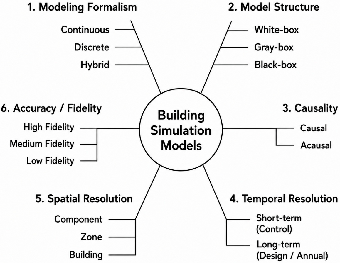
This heterogeneity spans multiple dimensions—modeling formalism, structural representation, causality, accuracy level, and spatial and temporal resolution [7,22]—as illustrated in Figure 1. No single modeling paradigm dominates across building simulation applications, which directly constrains tight model integration and motivates flexible interoperability approaches.
These differences are not only descriptive but also directly affect interoperability. In particular, mismatches in temporal resolution, causality, and model structure introduce constraints in terms of synchronization, data exchange, and solver compatibility, which become critical in distributed co-simulation contexts.

2.2. Interoperability Issues and Limits of Existing Approaches

The main characteristics of the different interoperability levels are summarized in Table 1, highlighting their respective capabilities and limitations in the context of distributed building simulation.
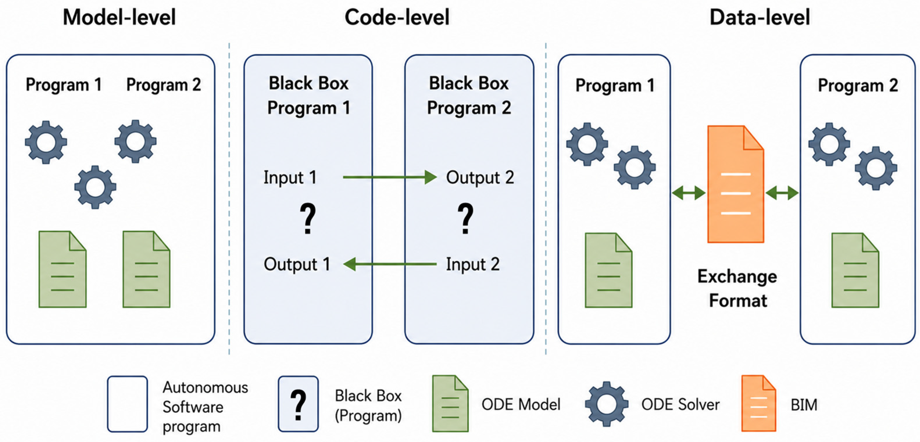
Interoperability in building simulation has traditionally been addressed at three main levels: data-level, model-level, and code-level interoperability, corresponding to increasing levels of integration and coupling between simulation tools, as illustrated in Figure 2.
Data-level approaches rely on standardized information models such as IFC to support structured data exchange between tools [10,11]. While effective for coordination and consistency of input data, these approaches do not support dynamic interaction between simulation models and therefore cannot represent coupled system behavior.
Model-level interoperability assumes shared modeling formalisms or unified simulation environments, enabling strong coupling and consistent multi-physics representations [12]. However, this approach generally requires re-implementation of models or access to internal equations, which limits reuse of existing models and reduces applicability in heterogeneous or proprietary simulation environments.
Code-level interoperability, including component-based frameworks such as FMI, promotes reuse of existing tools as black-box components [16]. This approach enables co-simulation between heterogeneous models but typically relies on direct coupling mechanisms with synchronization at discrete communication points. In distributed co-simulation contexts, frequent data exchanges and synchronization requirements may introduce communication overhead and reduce computational efficiency.
In this context, code-level approaches such as FMI focus on model coupling through component interfaces, whereas service-level approaches shift the focus toward orchestration and coordination of autonomous tools. These approaches are not mutually exclusive but address different integration contexts, with code-level coupling being more suited to tightly integrated environments and service-level approaches to distributed and loosely coupled workflows.
The recent release of FMI 3.0 [19] extends the standard with support for binary variables and clocks, partially addressing distributed execution scenarios. In particular, clock-based coordination in FMI 3.0 enables event-driven synchronization and can reduce unnecessary communication between components in asynchronous co-simulation contexts. However, FMI 3.0 retains a component-level coupling model that requires shared orchestration infrastructure and direct access to FMU interfaces. It should also be noted that the COSIMPHI demonstrator was developed before FMI 3.0 became available, using professional tools that could not be packaged as FMUs. The service-level approach investigated here was therefore motivated by these practical integration constraints rather than by a direct comparison with FMI 3.0 itself. In contrast, the service-level approach proposed here relies on service exchanges based on the Hypertext Transfer Protocol (HTTP), making it applicable to tools that cannot be packaged as FMUs, including legacy, proprietary, or remotely hosted simulation software.
Taken separately, these three levels of interoperability address distinct but complementary aspects of tool integration. Data-level approaches support consistent input representation but do not enable dynamic model interaction. Model-level approaches allow strong coupling but require re-implementation under a common formalism, which is impractical when tools are proprietary or independently developed. Code-level approaches such as FMI preserve tool encapsulation but assume co-located or tightly synchronized execution, which introduces prohibitive communication overhead in distributed contexts.
No existing approach simultaneously addresses the three constraints that arise in early-stage multi-performance building design: (i) tool autonomy—each simulation tool must remain independently developed, maintained, and executable; (ii) distributed execution—tools may run on separate machines or remote servers, making communication cost non-negligible; and (iii) flexible coupling—the coordination strategy must be adaptable at the workflow level without modifying the internal structure of any tool. This triple constraint defines the specific gap that service-level interoperability is designed to address.
Frameworks such as HELICS [20] have been developed to support large-scale distributed co-simulation in energy systems using a broker-based message-passing architecture. HELICS provides strong capabilities for coordinating federated simulators, managing time synchronization, and supporting scalable interactions between power, communication, and market models. However, its use generally requires each participating simulator to be integrated as a HELICS federate, with tool-specific adapters and configuration steps. This differs from the service-level approach investigated here, where tools are exposed through standard interfaces based on the Hypertext Transfer Protocol (HTTP) and Representational State Transfer (REST), and are coordinated externally without requiring framework-specific simulator integration.
The two approaches therefore target different interoperability contexts. HELICS is particularly well suited to large-scale cyber-physical energy systems and grid-oriented studies, where broker-mediated synchronization and federation management are central requirements. In contrast, the proposed service-oriented approach targets early-stage multi-performance building simulation workflows, where heterogeneous, independently developed tools must be coordinated with minimal assumptions on their internal implementation. From a communication perspective, HELICS relies on a dedicated co-simulation middleware and message-passing infrastructure, whereas the proposed approach relies on web-service exchanges through standard REST Application Programming Interfaces (APIs). This distinction is important because the objective of this work is not to replace dedicated co-simulation middleware, but rather to analyze how service-level interoperability affects coupling strategy design and communication overhead in distributed building simulation workflows.
To clarify the scope of the proposed contribution, Table 2 summarizes how the service-level approach differs operationally from FMI-oriented and HELICS-like co-simulation. The comparison is qualitative because the objective of this paper is to analyze the COSIMPHI orchestration strategy rather than to benchmark reimplemented versions of the same models in different frameworks.

3. Service-Oriented Approach for Interoperability

3.1. Service-Oriented Perspective on Interoperability

Service-oriented approaches have been investigated as a means to support distributed simulation and tool coupling in heterogeneous environments, particularly when direct model or code integration is impractical [16,23]. In the context of building simulation, such approaches aim to preserve tool autonomy while enabling coordinated execution through explicit interaction mechanisms rather than shared modeling formalisms [21].
From an interoperability standpoint, a service-oriented perspective shifts the focus from internal model representations to interaction capabilities between autonomous tools. Domain-specific simulation capabilities are exposed as services through standardized interfaces, providing a limited set of operations for execution control and data exchange. This abstraction avoids assumptions regarding internal model structure, numerical solvers, or time discretization schemes, which are often incompatible across domain-specific tools.
In this work, service-level interoperability is defined as the ability to coordinate autonomous simulation services through an external orchestration mechanism, without requiring direct access to internal model structures. Throughout this paper, the term “service-level” refers to the interoperability paradigm and architectural level, whereas “service-based” is used to describe the concrete implementation of co-simulation workflows through web-service exchanges. Each service encapsulates its own model and solver and interacts with other services exclusively through defined input and output interfaces.
Operationally, the proposed service-level approach differs from FMI- or HELICS-based integration by placing the coupling logic at the orchestration layer rather than inside exchanged model units or framework-specific federates. Each domain tool remains accessible as an autonomous service, while the orchestrator manages data mapping, synchronization windows, and coupling strategy selection. This makes the approach particularly suitable for legacy or professional building-performance tools that cannot easily be exported as FMUs or rewritten as dedicated co-simulation federates.
This orchestration-level positioning also distinguishes the proposed approach from code-level interoperability, where coupling is achieved through direct interactions between model components. Instead, coordination is managed at the orchestration level, where execution order, data exchange, and coupling iterations are explicitly controlled. This separation allows coupling strategies to be adapted independently of the simulation services while preserving tool autonomy.
From a practical standpoint, the service-level approach offers four main advantages for distributed building-performance workflows. First, it enables low-intrusion integration of existing tools, since each tool only needs to expose service interfaces while preserving its internal model and solver structure. Second, it supports geographically distributed execution, as services can run on separate machines or remote servers and communicate through web-service exchanges. Third, it allows coupling strategies to be modified at the orchestration level without changing the internal implementation of the coupled tools. These advantages are particularly relevant for professional, proprietary, or legacy simulation tools. Fourth, HTTP/HTTPS-based services communicate through standard ports (80 and 443) that are open by default on institutional networks and behind firewalls, significantly reducing the network configuration overhead associated with tools such as HELICS, which rely on non-standard Transmission Control Protocol (TCP) ports and require explicit network configuration. This facilitates deployment in multi-machine laboratory or university environments.
The approach also has limitations. Because services are accessed externally, communication overhead may become significant when high-frequency coupling is required. In addition, the absence of direct access to internal solver states limits the possibility of tight numerical coupling compared with model- or code-level approaches. The robustness of the workflow also depends on the quality of service contracts, data mapping, and network availability. These limitations motivate the use of orchestration-level coupling strategies, such as waveform relaxation, and are further evaluated in Section 4.
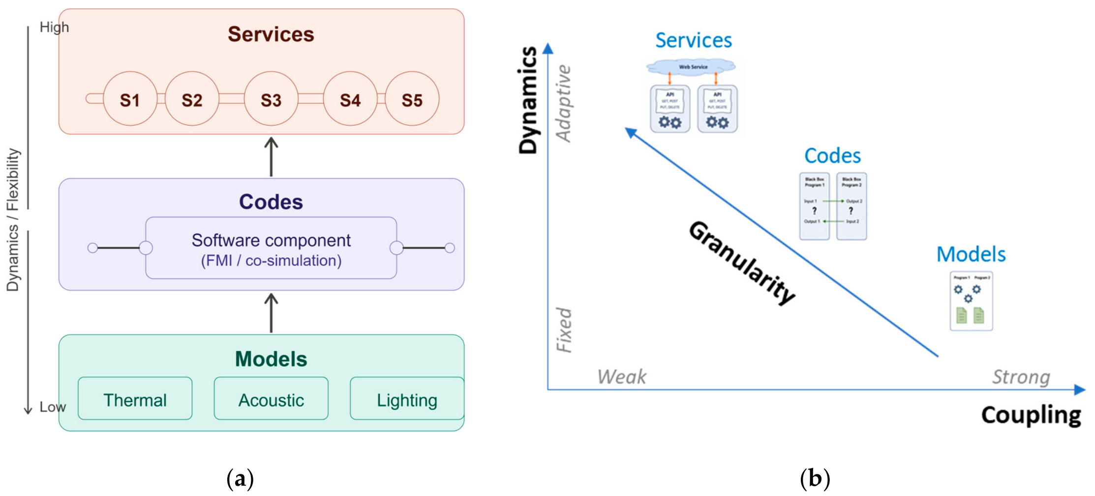
This perspective is further illustrated in Figure 3, which positions service-level interoperability with respect to model-level and code-level integration, while highlighting the trade-offs between coupling strength, execution flexibility, and interaction granularity.
The following subsections detail the data and model interoperability mechanisms required to support this service-oriented approach.

3.2. Data Interoperability

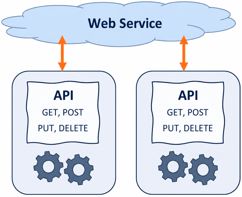
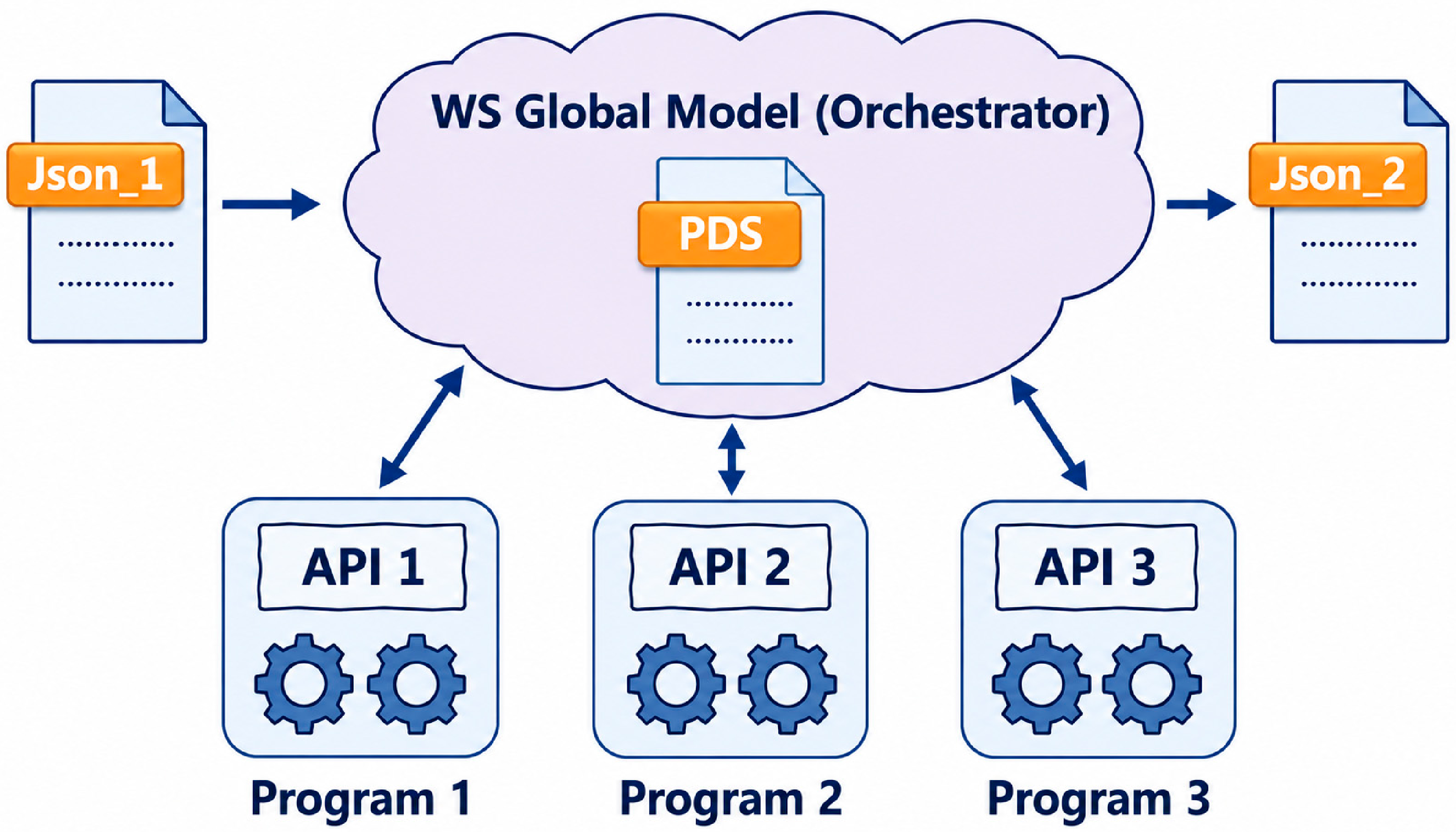
The implementation of this approach is illustrated in Figure 4, which shows how autonomous simulation programs interact through web-service interfaces while remaining internally independent.
Data interoperability relies on the identification and alignment of the information required by heterogeneous domain-specific simulation tools. In multi-performance building simulation, input data describing the same project must remain consistent across disciplines despite differences in modeling assumptions, spatial and temporal resolutions, and computational requirements.
Standard building information models such as IFC provide a shared structure for representing building data [10,11,25]. However, these models are not sufficient to ensure consistent data exchange between simulation services with different input requirements and internal representations.
To address the data alignment challenge across heterogeneous services, a Pivot DataSet (PDS) is defined as a structured intermediate dataset serving as the common reference for static input data in a service-oriented framework. The PDS does not aim to define a universal building simulation standard. Instead, it provides an extensible hierarchical JavaScript Object Notation (JSON) structure used to centralize the input data required by the different simulation services.
Formally, the PDS is organized around three complementary categories of parameters. Geometric parameters describe the physical topology of the building, including thermal zones, bounding surfaces, openings, and their spatial relationships. Intrinsic parameters characterize the physical properties of building components independently of their installation context, such as thermal conductivity, acoustic sound reduction indices, absorption coefficients, material density, and specific heat. Implementation parameters define the deployment conditions of components in the building, such as orientation, inclination, geographic location, system configuration, and usage schedules.
In a complete implementation, the hierarchy may contain nested objects describing buildings, thermal zones, boundaries, openings, walls, layers, ventilation systems, photovoltaic systems, usage zones, and outdoor conditions. Each simulation service extracts from the PDS only the subset of parameters relevant to its domain, using a service-specific data conversion layer at its interface. This design separates data consistency, managed at the PDS level, from data representation, which remains managed independently by each service.
The PDS contains only static parameters used for service initialization. Dynamic variables produced during co-simulation execution, such as indoor temperature trajectories, acoustic comfort indices, airflow values, or control signals, are not stored in the PDS but are exchanged directly between services through the orchestration mechanism at runtime.
It should be noted that the PDS was designed as a lightweight and extensible JSON structure for the specific needs of the COSIMPHI co-simulation workflow. Formal alignment with the IFC schema or with other standardized building data models was not pursued within the scope of the present work and therefore remains a direction for future standardization and interoperability refinement. In the present implementation, compatibility between PDS versions is not managed through a centralized schema-enforcement mechanism, but rather through controlled extensions of the data structure and service-specific parsers. A simplified structural excerpt and a formal tabular description of representative PDS fields are provided in Appendix A.1.

3.3. Model Interoperability via Service-Based Co-Simulation

3.3.1. Coupling Constraints Induced by Service-Based Integration

When simulation models are coupled through services, interoperability is achieved under specific constraints that differ from those of tightly integrated simulation environments. Each service encapsulates its own numerical solver and advances independently in time. As a result, direct access to internal states is not available, and synchronization between models relies exclusively on exchanged variables at discrete interaction points.
Service-based integration introduces communication delays and synchronization constraints, which depend on the frequency of data exchange and the distribution of simulation services. These constraints tend to weaken coupling strength and may negatively impact computational performance, particularly when frequent data exchanges are required. Consequently, coupling strategies must be designed explicitly to account for these limitations rather than attempting to replicate tightly coupled simulation schemes.
These constraints are explicitly managed at the orchestration level, where interaction frequency and data exchange between services are controlled.
Weak coupling strategies may introduce numerical stability and convergence limitations, particularly when coupled subsystems exhibit strong dynamic interactions or when synchronization intervals become large. As discussed in the co-simulation literature [24,26], the stability of weakly coupled co-simulation schemes depends on factors such as coupling strength, exchanged variables, synchronization frequency, and time-step selection.
In the present work, the objective is not to provide a formal numerical stability analysis of the waveform relaxation scheme, but rather to evaluate its computational behavior in a service-oriented interoperability context. The considered application corresponds to a relatively weak interaction scenario, where the exchanged variables evolve smoothly and remain compatible with iterative orchestration over time windows. Under these conditions, stable convergence behavior was observed for the selected synchronization configuration. These considerations motivate the use of waveform relaxation as a coupling strategy adapted to distributed service-oriented co-simulation contexts.

3.3.2. Performance-Oriented Coupling Strategy: Waveform Relaxation

Service-based co-simulation imposes specific coupling constraints related to distributed execution, limited access to internal solver states, and non-negligible communication overhead. Under these conditions, coupling strategies that rely on frequent synchronization or tight step-by-step coordination tend to become inefficient. A performance-oriented approach is therefore required to manage interaction frequency while maintaining consistent coupling behavior.
The waveform relaxation method (WRM), originally introduced by [27] for time-domain analysis of large-scale circuits, provides such an approach by iteratively coupling subsystems through exchanged interaction waveforms rather than isolated scalar values.
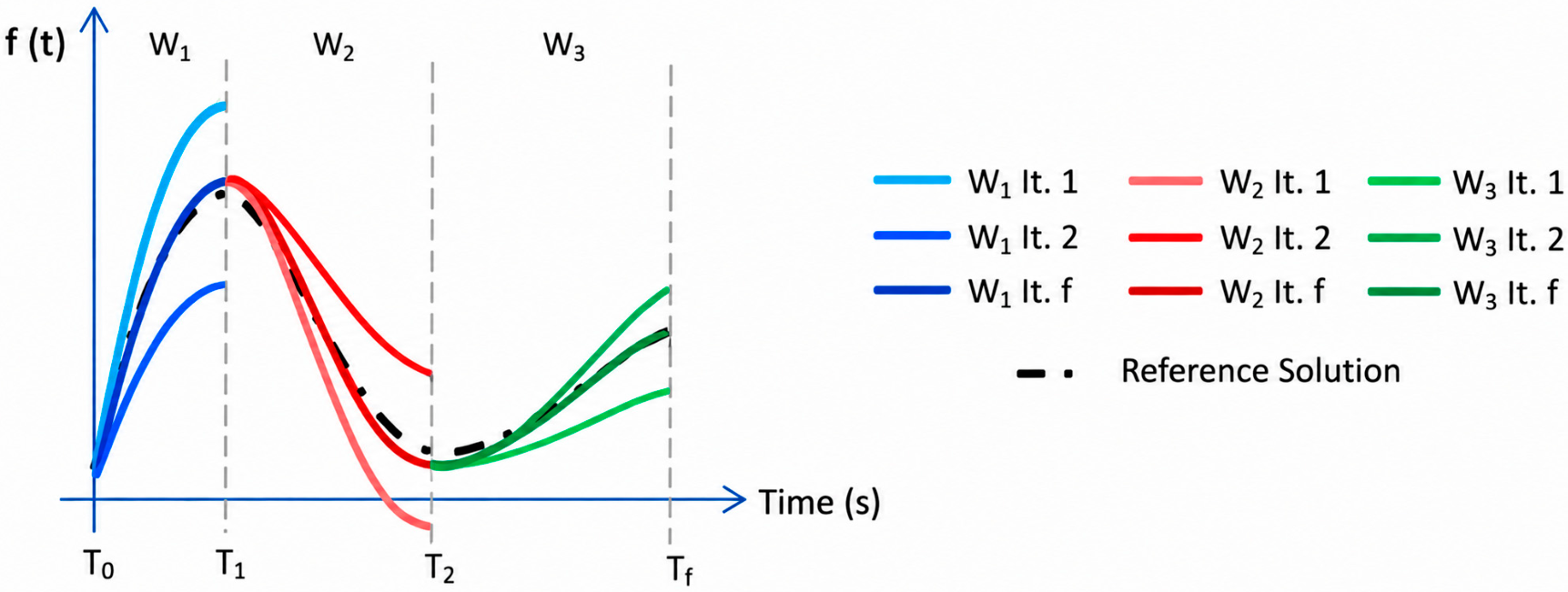
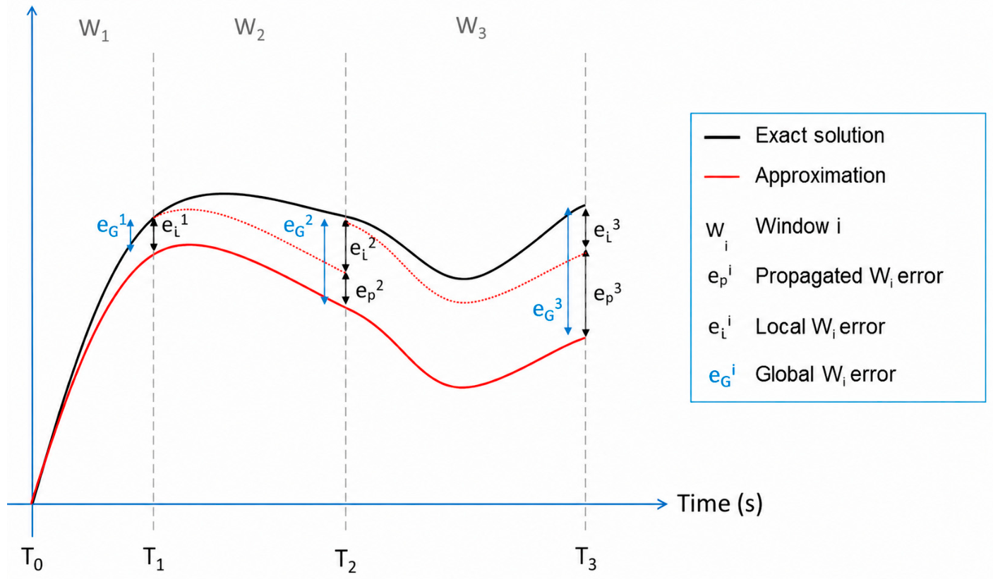
Within this framework, waveform relaxation is used as a coupling strategy adapted to the constraints of service-based integration. The method decomposes the simulation horizon into time windows over which each model is simulated independently using approximated interaction signals provided by the coupled models. These signals are iteratively updated until convergence criteria are satisfied for the considered window.
In waveform relaxation, convergence is assessed by monitoring the stabilization of the exchanged interaction waveforms across successive iterations. In this work, this stabilization is evaluated using the following relative residual criterion:
y k y k 1 1 + y k < ε
where y k denotes the interaction waveform at iteration k, and ε is a convergence tolerance. This criterion is used here as a practical stopping rule for the waveform relaxation process, consistently with the iterative convergence principles of waveform relaxation [27] and with convergence/error considerations commonly discussed in the co-simulation literature [24]. In the experiments presented in this work, a tolerance ε = 10−3 was selected as a practical engineering threshold balancing convergence stability and computational cost. This value was chosen to remain well below the level of physical precision expected from the simplified classroom models: in building energy and acoustic simulation contexts of this type, model simplifications and input-data uncertainties are commonly of order 10−1 to 10−2, so a convergence tolerance of 10−3 is sufficient to ensure that WRM iteration error is unlikely to be the limiting factor in the overall interpretation of the coupled results. In this sense, the objective of the tolerance is to stabilize the exchanged interaction waveforms rather than to enforce high-precision numerical integration of each individual domain model.
Under weak coupling conditions, waveform relaxation is expected to converge within a limited number of iterations, since the exchanged interaction signals progressively stabilize across successive iterations. The observed iteration counts reported in Section 4.3 are consistent with this objective: the WRM strategy converges in 10 iterations for the one-day simulation and 13 iterations for the one-month simulation, while strongly reducing the number of synchronization operations compared with minute-by-minute chaining.
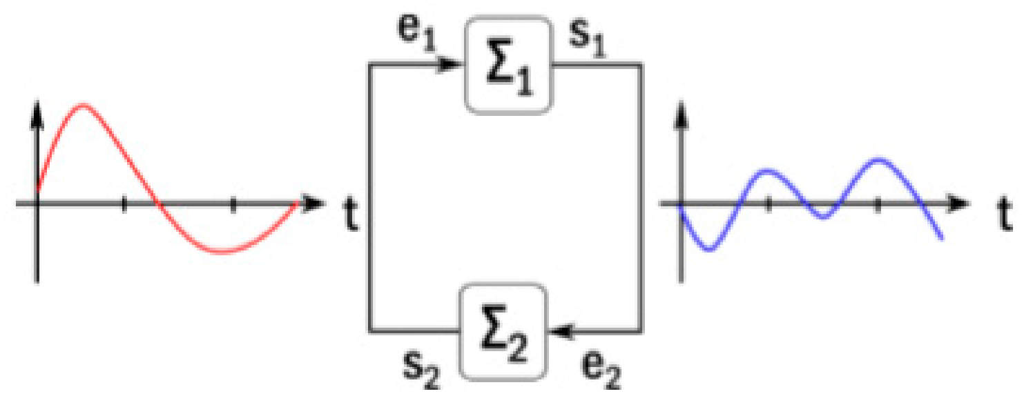
The principle of waveform relaxation is illustrated in Figure 5, which shows the iterative exchange of interaction waveforms between coupled subsystems over a given time interval [21]. Additional illustrative materials on the window-based behavior of waveform relaxation and the associated error-propagation mechanisms are provided in Appendix A.4.
From an interoperability perspective, the interest of waveform relaxation lies in its ability to decouple numerical integration from synchronization requirements. By limiting synchronization to window boundaries, the method reduces the number of inter-service exchanges compared to sequential chaining approaches. This property is particularly relevant in distributed co-simulation contexts, where communication latency and data transfer costs dominate execution time.
In the proposed framework, waveform relaxation is implemented at the orchestration level and remains independent of the simulation services themselves. Simulation services are treated as black-box components and are not required to expose internal states or modify their numerical solvers. This separation preserves tool autonomy while allowing coupling strategies to be adapted to execution constraints.
From an implementation perspective, the orchestration mechanism follows an iterative execution process over each time window. At each iteration, simulation services are executed, their outputs are exchanged, and interaction signals are updated until a convergence condition is satisfied.
Waveform relaxation does not eliminate the fundamental trade-offs associated with weak coupling and distributed execution. Instead, it provides a practical means to control synchronization frequency and communication overhead under service-level interoperability constraints. Its relevance is therefore assessed in terms of computational behavior rather than numerical optimality.
Additional illustrations of waveform relaxation behavior are provided in Appendix A.4.

4. Implementation and Evaluation of a Classroom Case Study

4.1. Case Study Description and Objectives

The proposed service-level interoperability approach is demonstrated using a classroom building case developed within the Agence Nationale de la Recherche (ANR) COSIMPHI project (ANR-13-VBDU-0002), coordinated by the Centre Scientifique et Technique du Bâtiment (CSTB). COSIMPHI was not conceived as a synthetic benchmark, but rather as a real multi-domain research demonstrator involving professional building-performance tools. In the present paper, a simplified single-classroom configuration is used to isolate and analyze the effects of service-based integration, orchestration, synchronization, and coupling strategies. The objective is to evaluate how heterogeneous professional tools can be coordinated within a distributed co-simulation workflow, using a controlled classroom configuration.
The main domain tools involved in the COSIMPHI implementation are summarized in Table 3.
The table reports the tools at the level required to describe the multi-domain co-simulation workflow. Specific software release numbers from the original experimental campaign were not preserved.
Within this multi-tool context, the reported classroom configuration was selected as a controlled case in which the exchanged variables, coupling effects, and orchestration behavior could be clearly observed.
The reported classroom configuration corresponds to a single classroom zone with a floor area of approximately 54 m2 and a ceiling height of 2.9 m. The building description includes walls, openings, ventilation systems, and occupancy-related parameters represented through the PDS structure described in Section 3.2 and Appendix A.1. Weather conditions and occupancy schedules are introduced as external boundary conditions during simulation.
The co-simulation workflow combines simplified thermal, ventilation, and acoustic models interacting through the service-oriented architecture described in Section 3. The thermal and ventilation services exchange information related to indoor temperature, outdoor conditions, occupancy, and window-opening commands. The acoustic service evaluates the impact of window-opening decisions on indoor acoustic conditions. These interactions are coordinated by the orchestration layer, which manages service calls, data exchange, and coupling decisions.
The regulation logic used to coordinate thermal and acoustic criteria can be summarized by the following orchestration-level pseudocode (Box 1).
Box 1. Orchestration-level pseudocode for the thermal–acoustic window-opening regulation logic in the COSIMPHI classroom case. Source: authors’ own formulation.
Input at time step t:
       T_in(t)                              — indoor air temperature (°C)
       T_out(t)                            — outdoor air temperature (°C)
       thermal_setpoint            — comfort temperature threshold (°C), fixed per scenario
       acoustic_indicator(t)  — indoor acoustic comfort index
                                                     (positive value = noise below regulation threshold;
                                                      negative value = noise exceeds regulation threshold)
       occupancy(t)                      — binary flag: 0 = unoccupied, 1 = occupied
       previous_window_state(t − 1) — initialized to CLOSED at t = 0
 
IF occupancy(t) == 0 THEN
       window_command(t) = CLOSED
ELSE IF T_in(t) > thermal_setpoint AND T_out(t) < T_in(t) THEN
       IF acoustic_indicator(t) > 0 THEN
              window_command(t) = OPEN
       ELSE
              window_command(t) = CLOSED
       END IF
ELSE
       window_command(t) = previous_window_state(t − 1)
END IF
This rule-based formulation is specific to the COSIMPHI classroom case. It makes explicit the orchestration-level decision logic: window opening requires a thermal condition (indoor temperature exceeds the setpoint and outdoor temperature is lower), an acoustic condition (indoor noise remains below the regulation threshold), and an occupancy condition. The evaluation time step corresponds to the coupling resolution used by the thermal and acoustic services in the COSIMPHI implementation.
The indoor comfort index is a simplified qualitative indicator used for regulation purposes within the COSIMPHI orchestration workflow. It takes values in a bounded range, where negative values indicate acoustically unfavorable conditions relative to the regulation threshold and positive values indicate acoustically acceptable conditions. The mapping from acoustic simulation outputs to index values is internal to the ACOUBAT-based acoustic service; in the present study, the index is therefore used as a control-oriented scalar within the orchestration logic rather than as a standardized or generally applicable acoustic comfort metric.
This configuration is therefore used as a representative test case for evaluating the impact of orchestration and coupling strategies on service-level interoperability, while keeping the physical configuration sufficiently controlled for analysis.
Additional illustrations of the coupling architecture and interaction structure used in the case are provided in Appendix A.2.
The following section describes how this case-study configuration is implemented within the service-based co-simulation workflow.

4.2. Service-Based Co-Simulation and Orchestration Setup

The classroom case is implemented using a set of autonomous simulation services exposed through web-service interfaces. These services are combined to support co-simulation within a service-oriented interoperability framework.
The organization of simulation services, data exchanges, and orchestration is illustrated in Figure 6. The exchanged JSON structures distinguish between configuration-oriented inputs used to initialize the simulation workflow (Json_1) and aggregated performance indicators returned by the orchestration process (Json_2).
In the broader COSIMPHI workflow, such aggregated indicators can be used by decision-support or optimization services to evaluate alternative design configurations through repeated service-based evaluations. However, in the present paper, these capabilities are considered as architectural extensions of the framework. The experimental evaluation reported here focuses on co-simulation behavior, orchestration logic, communication overhead, and coupling strategy selection, rather than on optimization convergence, objective-function performance, or Pareto-front generation.
Each service encapsulates a domain-specific model and its associated numerical solver and is accessed exclusively through a service interface. Services do not share internal states and are executed independently.
Service interactions are coordinated by an external orchestration mechanism responsible for managing execution order, data exchanges, and coupling iterations. Coupling strategies are implemented at the orchestration level and can be modified without altering the internal structure of the services.
Input data are provided through the PDS, which serves as a common reference for initializing services. During execution, dynamic variables are exchanged through the orchestrator according to the selected coupling strategy.
The orchestration layer therefore plays two complementary roles. First, it coordinates the execution of heterogeneous domain services during co-simulation. Second, it provides the computational structure required for repeated evaluations, which may later be exploited by optimization or decision-support workflows. In this article, only the first role is evaluated quantitatively through the co-simulation results reported in Section 4.3.
Optimization is therefore not treated as an experimental result in the present study. It is mentioned only as a capability supported by the broader service-oriented architecture, since optimization workflows require repeated calls to the same heterogeneous simulation services. The analysis of optimization quality, convergence behavior, objective-function performance, and Pareto-front generation is outside the scope of the reported results.
This setup enables the coordinated execution of heterogeneous simulation services in a distributed co-simulation context, while maintaining service independence and allowing flexible adaptation of coupling strategies.
Additional illustrations of service interactions across multiple domains are provided in Appendix A.3.

4.3. Performance Evaluation and Results

The objective of this section is to evaluate the computational behavior induced by the service-based co-simulation workflow. The analysis focuses on how orchestration and coupling strategies affect execution behavior in a distributed service-oriented context, using execution time, web-service exchange counts, and synchronization iteration counts as performance indicators.
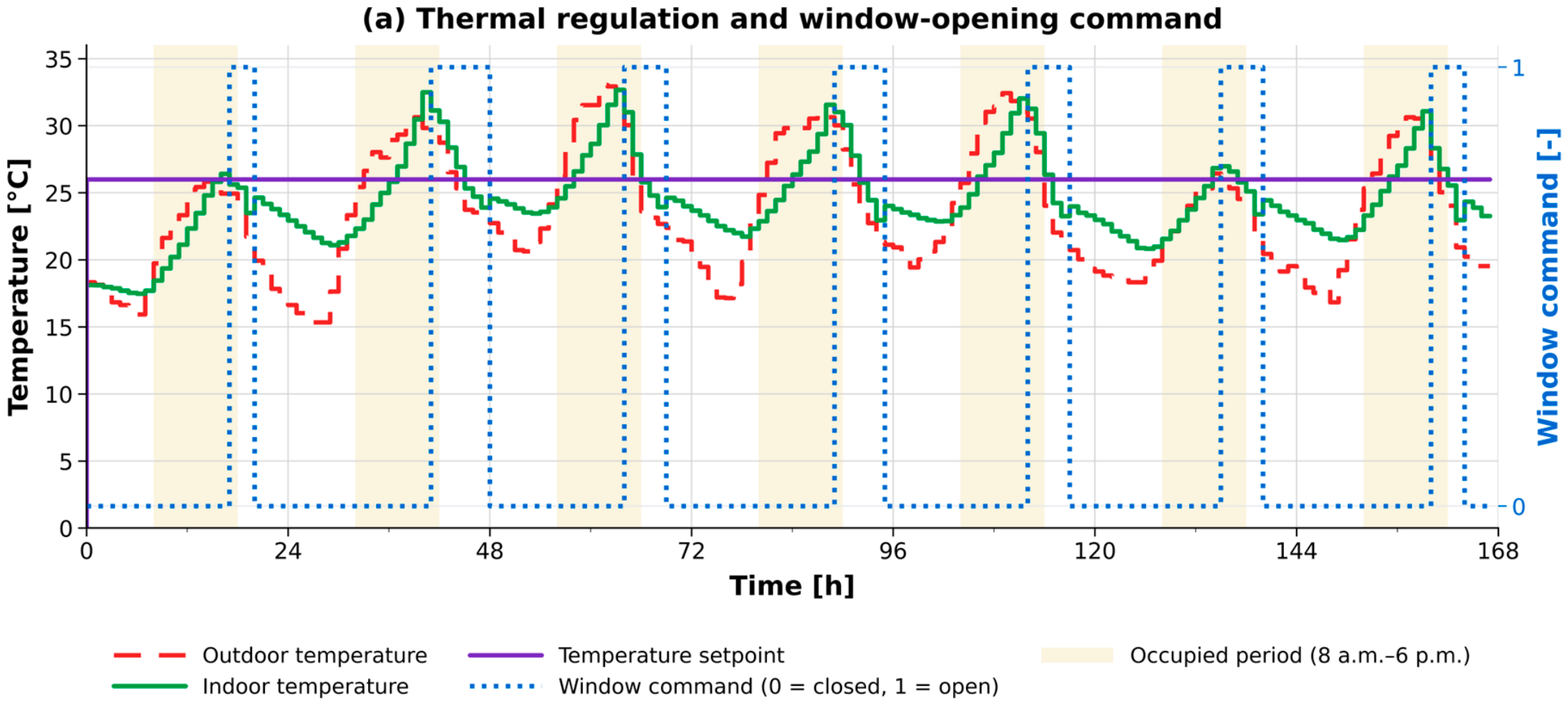
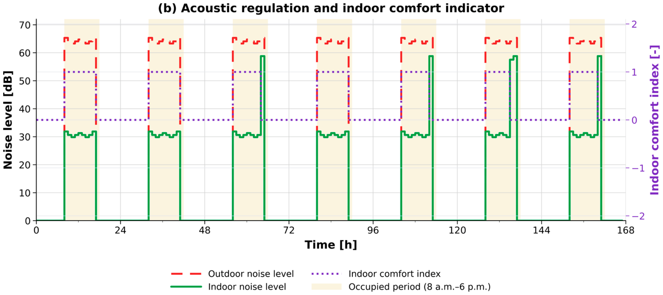
Figure 7 illustrates the interaction between thermal regulation, acoustic regulation, and opening-management strategies during a representative summer week. The upper graph shows the evolution of indoor and outdoor temperatures together with window-opening commands, while the lower graph presents the interaction between indoor acoustic conditions and the associated indoor comfort index. The indoor comfort index corresponds to a simplified qualitative comfort indicator used for regulation purposes, where negative and positive values represent under- and over-comfort conditions relative to the target comfort range.
Several coupled behaviors can be observed from Figure 7. First, indoor temperature variations remain bounded despite changing outdoor conditions and repeated opening actions. Window-opening commands occur mainly during occupied periods and are associated with reductions in indoor temperature peaks following high outdoor thermal conditions. Second, window-opening commands evolve dynamically in response to the coupled regulation strategy, illustrating the interaction between thermal and acoustic service exchanges coordinated at the orchestration level. Third, indoor acoustic levels remain significantly lower than outdoor noise levels during occupied periods, while the indoor comfort index remains within the targeted regulation range.
These observations illustrate the ability of the proposed service-oriented co-simulation framework to coordinate heterogeneous simulation services while maintaining stable interaction behavior under distributed coupling conditions. They also provide a qualitative interpretation of the orchestration logic introduced in Section 4.1, where thermal and acoustic criteria are combined to generate the window-opening command.
The execution times reported in the following tables correspond to observed values obtained during the COSIMPHI experimental campaign. The experiments were run on a Dell workstation (Dell Inc., Round Rock, TX, USA) equipped with an Intel Core i5 processor (Intel Corporation, Santa Clara, CA, USA) and connected to the Grenoble Electrical Engineering Laboratory (G2Elab) local area network (LAN). Since the original individual timing logs from the COSIMPHI experimental campaign are no longer available, exact standard deviations and confidence intervals cannot be recomputed. The values reported should therefore be understood as session-average or campaign-period observations rather than statistically characterized means. For this reason, comparisons between coupling strategies rely primarily on structural coupling metrics, such as the number of synchronization iterations and web-service exchanges, which are determined by the coupling strategy configuration and are more reproducible than wall-clock timing measurements, which depend on hardware and network conditions.
The computational cost associated with service-based co-simulation is quantified in Table 4, which reports execution times and the number of web-service exchanges for different coupling configurations.
The results indicate that execution time is strongly influenced by the synchronization frequency imposed by the coupling strategy. In the service-oriented configuration, the dominant computational overhead is associated with repeated inter-service exchanges rather than with the internal execution cost of the simplified simulation models themselves.
This behavior is particularly visible in the sequential chaining configuration, where each synchronization step requires a complete service interaction cycle. As the simulation horizon increases, the number of exchanges grows proportionally to the number of coupling steps, leading to a rapid increase in execution time under distributed conditions.
By contrast, waveform relaxation reduces the synchronization frequency by exchanging complete interaction waveforms over larger time windows. Consequently, the number of inter-service communication events remains limited compared to sequential chaining, which explains the significantly lower execution times observed for long simulation horizons.
It should also be noted that the relative contribution of communication overhead depends on model complexity. In the present study, simplified thermal and acoustic models are used, which makes communication costs comparatively dominant. For more computationally intensive simulation models, the proportion of time associated with numerical computation would increase relative to communication overhead, although synchronization costs would remain a critical factor in distributed co-simulation workflows.
The impact of coupling strategy selection is further analyzed in Table 5, which compares waveform relaxation and sequential chaining for different simulation horizons and execution contexts. The comparison shows that waveform relaxation significantly reduces the number of coupling iterations required for service-based co-simulation, particularly for longer simulation periods. In contrast, sequential chaining leads to a rapid increase in synchronization steps, resulting in a substantial increase in inter-service communication.
For the one-day simulation, sequential chaining requires 1440 synchronization iterations, corresponding to one synchronization per minute. In contrast, the waveform relaxation strategy converges in 10 iterations. This corresponds to a reduction factor of 144× in the number of synchronization iterations. For the one-month simulation, sequential chaining requires 43,145 synchronization iterations, whereas waveform relaxation converges in 13 iterations, corresponding to an approximately 3319× reduction.
These reductions are not primarily hardware-dependent timing effects. They result from the structure of the coupling strategy itself: sequential chaining synchronizes the services at every time step, while waveform relaxation reduces the number of synchronization operations by exchanging and updating interaction waveforms over larger time windows. The iteration counts, therefore, provide a more robust indicator of the benefit of waveform relaxation in a service-based orchestration context than absolute execution time alone.
The near-constant number of WRM iterations across simulation horizons (10 for one day, 13 for one month) reflects the physical characteristics of the thermal-acoustic coupling in the studied configuration. In this case, the interaction between the two subsystems is mediated through building openings and ventilation flows—a weak coupling in the sense that each subsystem’s dynamics are largely independent. Under such conditions, WRM waveforms converge within a small number of iterations, regardless of the simulation horizon, as the interaction signals quickly reach a stable approximation. This property is fundamental to the efficiency of WRM in service-based contexts: since the number of inter-service exchanges equals the number of WRM iterations, not the number of time steps, the total communication cost scales sublinearly with simulation duration.
This low iteration count should therefore be interpreted in relation to the weak-coupling nature of the classroom configuration. Under stronger bidirectional coupling, multi-zone configurations, or discontinuous regulation mechanisms, the convergence behavior of WRM may differ, and additional iterations may be required to stabilize the exchanged waveforms. These configurations are discussed further in Section 5, where they are presented as limitations and perspectives for future work.
In the local execution context, sequential chaining outperforms WRM for the one-day horizon because network transfer costs are absent and each chaining iteration exchanges only a scalar value at a single time step. WRM, by contrast, exchanges complete waveforms—vectors covering the full simulation horizon—at each iteration, which introduces a higher per-iteration cost even locally. This reversal of performance ranking between local and distributed contexts highlights a key implication for coupling strategy selection: WRM is not universally faster but becomes advantageous specifically when communication latency is non-negligible, which is the defining condition of service-level interoperability. In this context, the reported WRM iteration time includes the manipulation and exchange of complete interaction waveforms over each synchronization window.
The speedup ratio of WRM over sequential chaining decreases slightly as the simulation horizon increases in the distributed setting. This is consistent with the marginal increase in WRM iteration count, from 10 to 13, which reflects the progressive accumulation of interaction complexity over longer horizons. Sequential chaining, by contrast, scales strictly linearly with the number of time steps.
It should be noted that the number of chaining iterations is directly proportional to the ratio of simulation horizon to coupling time step, while WRM iteration count is largely independent of this ratio. Reducing the coupling time step from one hour to fifteen minutes would multiply chaining iterations by four, while leaving the WRM iteration count approximately unchanged. This asymmetry becomes increasingly relevant as model accuracy requirements impose finer time resolutions.
This behavior is consistent with the convergence discussion in Section 3.3.2, where the tolerance ε = 10−3 was selected as a practical compromise between convergence stability and computational cost. The observed iteration counts confirm that this tolerance is sufficient for the considered weak-coupling regime.
These results should be interpreted as a case-study-based evaluation of the service-level coupling strategy. They demonstrate how orchestration choices affect communication overhead and synchronization requirements in the COSIMPHI classroom case. They are not intended to define universal hardware-independent performance benchmarks for all distributed building co-simulation configurations.

5. Discussion

The COSIMPHI classroom evaluation demonstrates that service-level interoperability is technically feasible for coordinating heterogeneous building-performance tools without requiring unified modeling formalisms, and that coupling strategy selection—rather than internal model complexity—is the dominant determinant of execution cost in distributed service-oriented co-simulation workflows. This positioning differs from tightly integrated co-simulation frameworks, where interoperability often depends on shared numerical infrastructures or framework-specific integration mechanisms. In the proposed approach, interoperability is achieved through autonomous services interacting via standard HTTP/REST exchanges coordinated externally at the orchestration level.
A central outcome of the evaluation is that computational performance in service-based co-simulation is strongly influenced by the choice of coupling strategy rather than by the internal efficiency of individual simulation services. The results indicate that frequent synchronization and data exchange can rapidly dominate execution time in service-oriented execution environments. In this context, waveform relaxation provides an effective approach to limit the number of coupling interactions and reduce communication overhead, although its role here is primarily to manage synchronization cost rather than to improve the numerical accuracy of the individual solvers.
The comparison between waveform relaxation and sequential chaining highlights an important trade-off. While sequential chaining may remain efficient for tightly coupled or locally executed simulations, its scalability is limited in service-oriented settings due to the large number of required synchronization steps. Waveform relaxation, by contrast, reduces synchronization frequency through iterative exchanges over time windows, which improves feasibility for longer simulation horizons. These observations suggest that coupling strategies must be selected with explicit consideration of execution context, synchronization frequency, and interoperability constraints.
From a practical standpoint, these results also help position service-level orchestration with respect to FMI- and HELICS-based workflows. The reported comparison should not be interpreted as a direct benchmark against these frameworks, since the COSIMPHI tools were not reimplemented as FMUs or HELICS federates. However, the results show that, in a service-level setting, the dominant performance factor is the number of synchronization and communication events imposed by the coupling strategy. This observation is relevant beyond the specific implementation: any distributed workflow requiring frequent tool-to-tool synchronization may be affected by similar communication overhead, whereas orchestration-level strategies such as WRM can reduce this overhead by exchanging interaction waveforms over larger synchronization windows.
An additional practical advantage of HTTP/HTTPS-based service communication is its simplicity of network deployment: standard web ports (80 and 443) are open by default on institutional and corporate networks, whereas tools relying on non-standard Transmission Control Protocol (TCP) ports require explicit firewall and network configuration, which may represent a significant barrier in distributed or multi-organizational co-simulation contexts.
These findings are consistent with observations reported in the broader co-simulation literature. Gomes et al. [24] identify synchronization frequency as a major source of computational overhead in weakly coupled distributed co-simulation configurations, particularly when communication latency becomes non-negligible. Similarly, previous investigations conducted within the same research framework [21] showed that waveform relaxation can substantially reduce the number of required synchronization exchanges in building energy co-simulation contexts compared to step-by-step coupling approaches. The near-constant WRM iteration count observed in the present study for increasing simulation horizons is also consistent with the expected behavior of weakly coupled interaction signals under waveform relaxation–based synchronization.
The presented results should nevertheless be interpreted primarily as an analysis of interoperability behavior rather than as a benchmark of numerical simulation performance. The study focuses on evaluating how distributed service interactions influence coupling behavior and execution cost in a multi-domain simulation workflow, rather than on solver accuracy or hardware-independent performance benchmarking. In the investigated configuration, communication overhead becomes a dominant factor because simplified thermal and acoustic models are used, making synchronization costs proportionally more significant than the internal computation cost of the models themselves.
From a practical perspective, the proposed service-oriented approach appears particularly relevant during exploratory and early-stage design phases, where heterogeneous tools, independently developed simulation models, and evolving workflows must coexist without requiring deep software integration. The orchestration-level implementation of coupling strategies also allows simulation services to remain autonomous while preserving flexibility in workflow organization. Such characteristics may facilitate the integration of legacy simulation tools, distributed computational resources, and domain-specific services within broader decision-support environments.
The proposed architecture also has implications for future simulation-based optimization workflows, since such workflows typically require repeated evaluations of heterogeneous domain services. In that context, reducing synchronization frequency and communication overhead is a prerequisite for practical feasibility. However, the present study does not evaluate optimization quality, convergence properties, objective-function performance, or Pareto-front generation. Optimization is therefore considered here only as a possible extension of the service-level orchestration framework.
Several limitations of the present study must nevertheless be emphasized. The classroom case should first be interpreted as a controlled weak-coupling test case rather than as a general proof of scalability for all building co-simulation configurations. The evaluation is based on a single classroom case and a restricted set of coupled services. The investigated configuration corresponds to a relatively weak-coupling scenario involving simplified thermal and acoustic interactions. This controlled setting is useful for isolating the effect of service orchestration and coupling strategy selection, but it does not cover multi-zone configurations, complex geometries, or strongly bidirectional interactions. Stronger nonlinear interactions or tightly coupled systems may exhibit significantly different convergence and stability behavior, particularly when fast bidirectional feedback mechanisms are present.
An additional limitation concerns the behavior of waveform relaxation under nonlinear or discontinuous coupling conditions. Previous investigations conducted within the same research framework [21] showed that regulation mechanisms involving hysteresis may significantly degrade WRM convergence behavior. In such cases, discontinuities introduced by switching events destabilize the exchanged interaction waveforms and may lead to a substantial increase in the number of required iterations. Earlier experiments involving hysteresis-based heating regulation models showed that WRM convergence could become progressively sequential across the simulation horizon, requiring significantly more iterations than in the weakly coupled thermal-acoustic configuration investigated in the present study. These observations suggest that the efficiency of waveform relaxation strongly depends on the smoothness and dynamic characteristics of the exchanged interaction variables.
This point is particularly important for extending the approach beyond the present weakly coupled classroom configuration, since stronger couplings or discontinuous control laws may reduce the advantage observed in the reported case study.
Furthermore, the present work does not provide a rigorous numerical stability analysis of the co-simulation algorithms, nor a hardware-independent benchmarking evaluation. The reported execution times should therefore be interpreted as average observed values within the considered COSIMPHI case study rather than as universal performance indicators. Real-time constraints, large-scale distributed deployments, and industrial-scale multi-domain workflows also remain outside the scope of the current evaluation.
Overall, the results indicate that service-oriented interoperability provides a flexible framework for coordinating heterogeneous simulation services in distributed building-performance workflows. In such contexts, explicit management of synchronization constraints, communication overhead, and coupling strategies becomes a central requirement for maintaining feasible execution behavior as simulation workflows increase in complexity and distribution scale. Future work should therefore evaluate the proposed orchestration strategy on multi-zone building configurations, stronger bidirectional coupling regimes, and control laws involving discontinuities or switching events, in order to assess the robustness of WRM-based service coupling under more demanding conditions.

6. Conclusions and Perspectives

This paper shows that service-level interoperability—implemented through web-service orchestration without access to internal model structures—provides a viable coordination strategy for heterogeneous building-performance tools, and that coupling strategy selection at the orchestration level has a decisive impact on execution feasibility in distributed co-simulation workflows. This was demonstrated through the COSIMPHI classroom case study, which provided a controlled evaluation of the framework’s architectural design, orchestration behavior, and communication-overhead characteristics. The proposed architecture exposes heterogeneous building-performance tools as autonomous web services, coordinates them through an external orchestration layer, and structures data exchange through a Pivot DataSet. This positioning is particularly relevant when professional tools must preserve autonomy, intellectual property, and heterogeneous execution environments.
The case study shows that the coupling strategy has a direct impact on communication overhead. In the reported weak-coupling configuration, waveform relaxation reduces the number of synchronization iterations by 144× over a one-day simulation and by approximately 3319× over a one-month simulation compared with minute-by-minute sequential chaining. These reductions are primarily due to the structure of the coupling strategy: WRM exchanges interaction waveforms over larger synchronization windows, whereas sequential chaining requires service synchronization at every time step.
The results therefore support two main conclusions. First, service-level interoperability can provide a flexible integration layer for coordinating heterogeneous building-performance tools without requiring a common modeling formalism or framework-specific simulator integration. Second, orchestration-level coupling strategies are essential in distributed co-simulation workflows because communication overhead and synchronization frequency can dominate execution behavior when services are executed remotely or through web-service interfaces.
The study remains limited to a controlled classroom configuration and to a weak thermal–acoustic coupling regime. The reported iteration reductions should therefore not be interpreted as universal performance gains for all building co-simulation configurations. Three directions are identified for future work. First, the approach should be extended to multi-zone building configurations with stronger bidirectional coupling between thermal, acoustic, and other performance domains, where the weak-coupling assumption adopted in the present classroom case no longer holds and WRM convergence behavior may differ substantially. Second, the robustness of the WRM strategy under discontinuous or hysteresis-based regulation mechanisms should be evaluated, since switching events may degrade convergence and reduce the communication-efficiency advantage observed in the present study. Third, a benchmark configuration based on an open reference building model and a shared coupling scenario should be designed to enable more systematic comparison between service-level, FMI-based, and HELICS-based orchestration strategies under equivalent coupling conditions.

Author Contributions

Conceptualization, A.R. and B.D.; methodology, A.R.; software, A.R.; validation, A.R. and B.D.; formal analysis, A.R.; investigation, A.R.; writing—original draft preparation, A.R.; writing—review and editing, B.D.; supervision, B.D. All authors have read and agreed to the published version of the manuscript.

Funding

This research was funded by the French National Research Agency (ANR), grant number ANR-13-VBDU-0002.

Institutional Review Board Statement

Not applicable.

Informed Consent Statement

Not applicable.

Data Availability Statement

Two categories of results are reported in this study. First, the structural coupling metrics—specifically the numbers of synchronization iterations required by sequential chaining and waveform relaxation for each simulation horizon—are fully reproducible from the coupling strategy formulations and parameter values described in Section 3.3 and Section 4.3, independently of any simulation software. Second, the execution-time values reported in Table 4 and Table 5 are case-specific and depend on the hardware and network conditions described in Section 4.3. The original detailed execution logs are no longer available; the reported values correspond to representative averages observed during the COSIMPHI experiments and are provided for indicative comparison of coupling strategies rather than as hardware-independent benchmarks. Requests for additional information may be addressed to the corresponding author.

Acknowledgments

The authors acknowledge the contributions of the project consortium involved in the development of the case study.

Conflicts of Interest

The authors declare no conflicts of interest.

Abbreviations

The following abbreviations are used in this manuscript:
ANRAgence Nationale de la Recherche
APIApplication Programming Interface
BIMBuilding Information Modeling
CSTBCentre Scientifique et Technique du Bâtiment
FMIFunctional Mock-up Interface
FMUFunctional Mock-up Unit
G2ElabGrenoble Electrical Engineering Laboratory
HELICSHierarchical Engine for Large-scale Infrastructure Co-Simulation
HTTPHypertext Transfer Protocol
HTTPSHypertext Transfer Protocol Secure
IFCIndustry Foundation Classes
JSONJavaScript Object Notation
LANLocal Area Network
ODEOrdinary Differential Equation
PDSPivot DataSet
RESTRepresentational State Transfer
TCPTransmission Control Protocol
WRMWaveform Relaxation Method
WSWeb services

Appendix A. Supplementary Illustrative Material

Appendix A.1. Simplified PDS Structure and Representative Fields

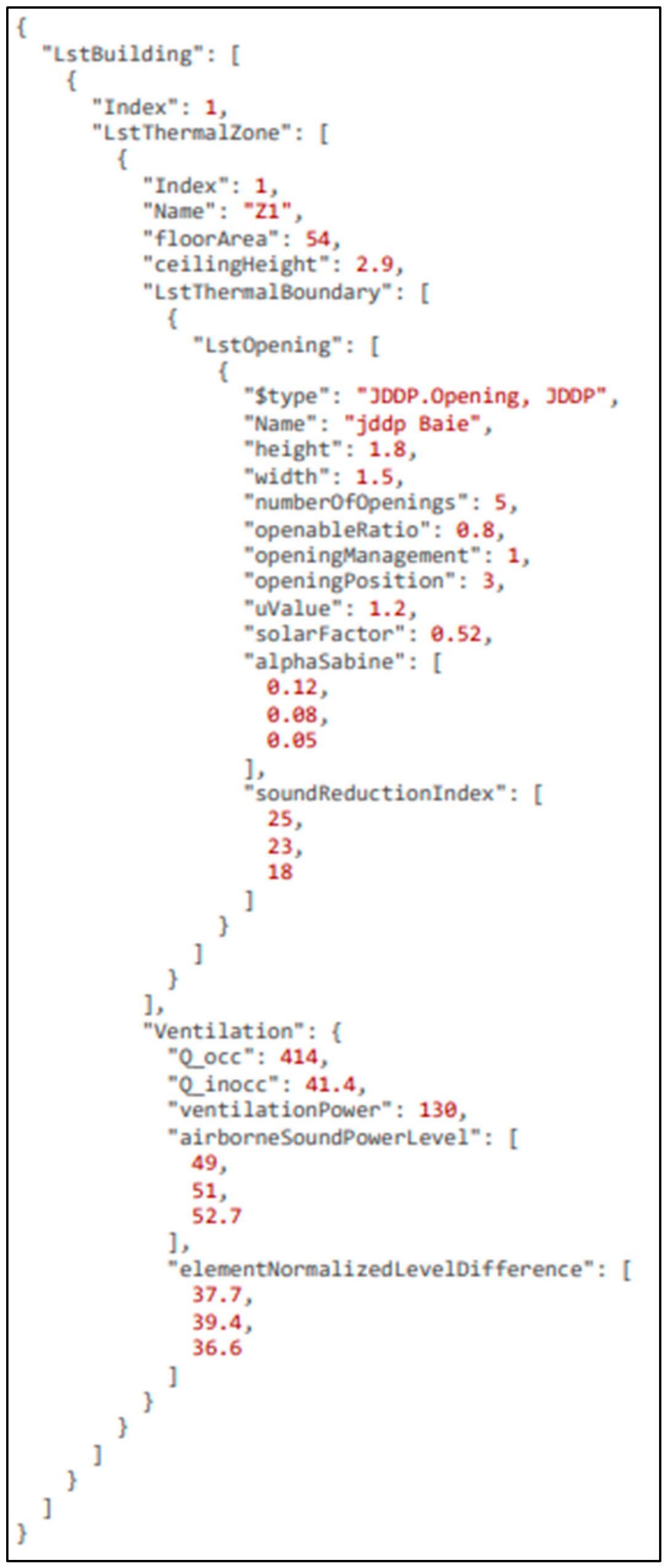
The following appendix provides both a simplified JSON excerpt (Figure A1) and a formal tabular description of representative PDS fields (Table A1) used for data exchange between simulation services. It focuses on a subset of variables associated with thermal and acoustic interactions through building openings and ventilation.
Table A1. Simplified formal structure of the PDS hierarchy.
LevelMain Object/FieldTypeRequiredDescription
RootDescriptionstring/nullOptionalGeneral description of the dataset
RootIndexintegerRequiredIdentifier of the dataset instance
RootVersionstring/nullOptionalVersion identifier of the dataset structure
RootLstBuildingarrayRequiredList of building objects
BuildingNamestringOptionalBuilding name
BuildingaddressobjectOptionalLocation-related information such as altitude and department
BuildingLstThermalZonearrayRequiredList of thermal zones contained in the building
BuildingLstPVarrayOptionalPhotovoltaic system descriptions
BuildingLstUsageZonearrayOptionalUsage and occupancy-related parameters
BuildingOutdoorConditionsobjectOptionalMeteorological data source and path
Thermal zoneNamestringOptionalName of the thermal zone
Thermal zonefloorAreanumberRequiredFloor area of the zone
Thermal zoneceilingHeightnumberRequiredCeiling height of the zone
Thermal zoneLstThermalBoundaryarrayRequiredList of thermal boundaries associated with the zone
Thermal zoneVentilationobjectOptionalVentilation flow rates, acoustic levels, and ventilation power
Thermal zoneLightingobjectOptionalLighting system parameters
Thermal boundaryazimuthnumberOptionalOrientation of the boundary
Thermal boundaryinclinationnumberOptionalInclination angle of the boundary
Thermal boundaryLstWallarrayOptionalWall, roof, or floor components
Thermal boundaryLstOpeningarrayOptionalWindows, doors, and other openings
Thermal boundaryLstAirIntakearrayOptionalAir intake components
Openingheight, widthnumberRequiredGeometric dimensions of the opening
OpeninguValuenumberOptionalThermal transmittance
OpeningsolarFactornumberOptionalSolar factor of the opening
OpeningsoundReductionIndexarray[number]OptionalAcoustic sound reduction values by frequency band
Wall/layerLstLayerarrayOptionalLayered wall description
Layer componentconductivitynumberOptionalThermal conductivity
Layer componentdensitynumberOptionalMaterial density
Layer componentspecificHeatnumberOptionalSpecific heat capacity
Layer componentthicknessnumberOptionalLayer thickness
VentilationQ_occ, Q_inoccnumberOptionalOccupied and unoccupied airflow rates
VentilationventilationPowernumberOptionalVentilation system power
VentilationairborneSoundPowerLevelarray[number]OptionalAirborne sound power levels by frequency band
VentilationelementNormalizedLevelDifferencearray[number]OptionalAcoustic level difference values by frequency band
Figure A1. Simplified example of the PDS structure used for service-based co-simulation.
Applsci 16 06755 g0a1
The complete dataset includes additional parameters related to geometry, materials, energy systems, acoustic properties, and other simulation domains. For clarity, the example is limited to a single thermal zone, one opening element, and a reduced number of acoustic frequency-band values.
For instance, acoustic parameters such as sound reduction indices and absorption coefficients are used by acoustic simulation services, while airflow rates and ventilation power are used by thermal and airflow models.
Unless otherwise specified, lengths are expressed in m, areas in m2, thermal transmittance in W·m−2·K−1, airflow rates in m3·h−1, ventilation power in W, and acoustic quantities are expressed as frequency-band values.
Figure A1 illustrates the hierarchical organization of the PDS through a simplified JSON representation. Table A1 summarizes representative structural fields, associated data types, and their role within the framework.
This table provides a simplified formal view of the PDS hierarchy based on the complete dataset used in the case study. Only representative fields are shown. Required fields indicate structural elements needed to identify the building, zones, and main components; domain-specific parameters remain optional and are extracted only by the services that require them.

Appendix A.2. Illustrative REST-Based Service Interaction

This appendix provides an illustrative example of a co-simulation web service interface used within the proposed service-oriented framework. The example corresponds to an energy simulation service and is summarized in Table A2, which lists the main operations exposed through a REST-based API.
Table A2. Example of an energy co-simulation web service interface: Energy calculation engine controller.
URL Address Operation Method Input Output
…/EnergyWS/InitializationPUTPDSSession key {Id}
…/EnergyWS/{Id}ComputeStepPOSTn/a{Output.Energy} for one step
…/EnergyWS/{Id}GetAllResultsGETn/aCumulative {Output.Energy}
…/EnergyWS/{Id}DeleteDELETEn/an/a
n/a: not applicable.

Appendix A.3. Illustrative Service Interaction and Orchestration Architecture

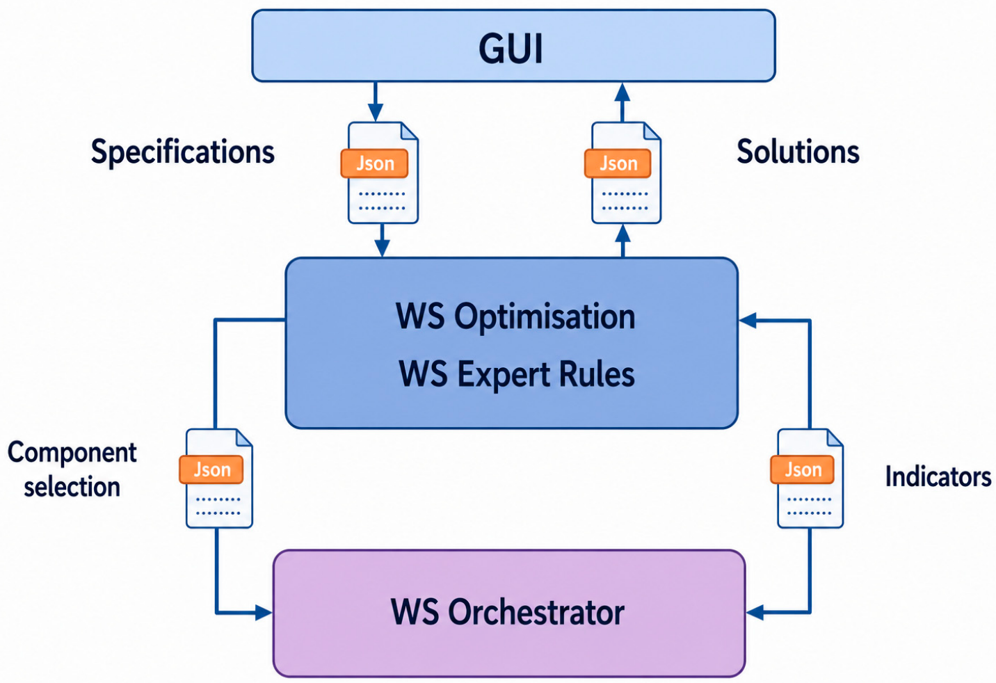
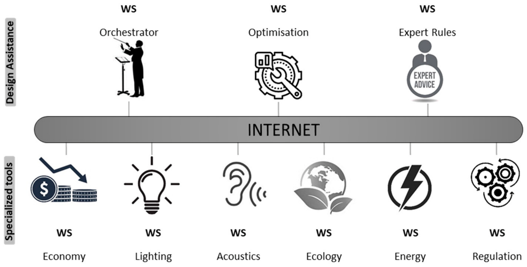
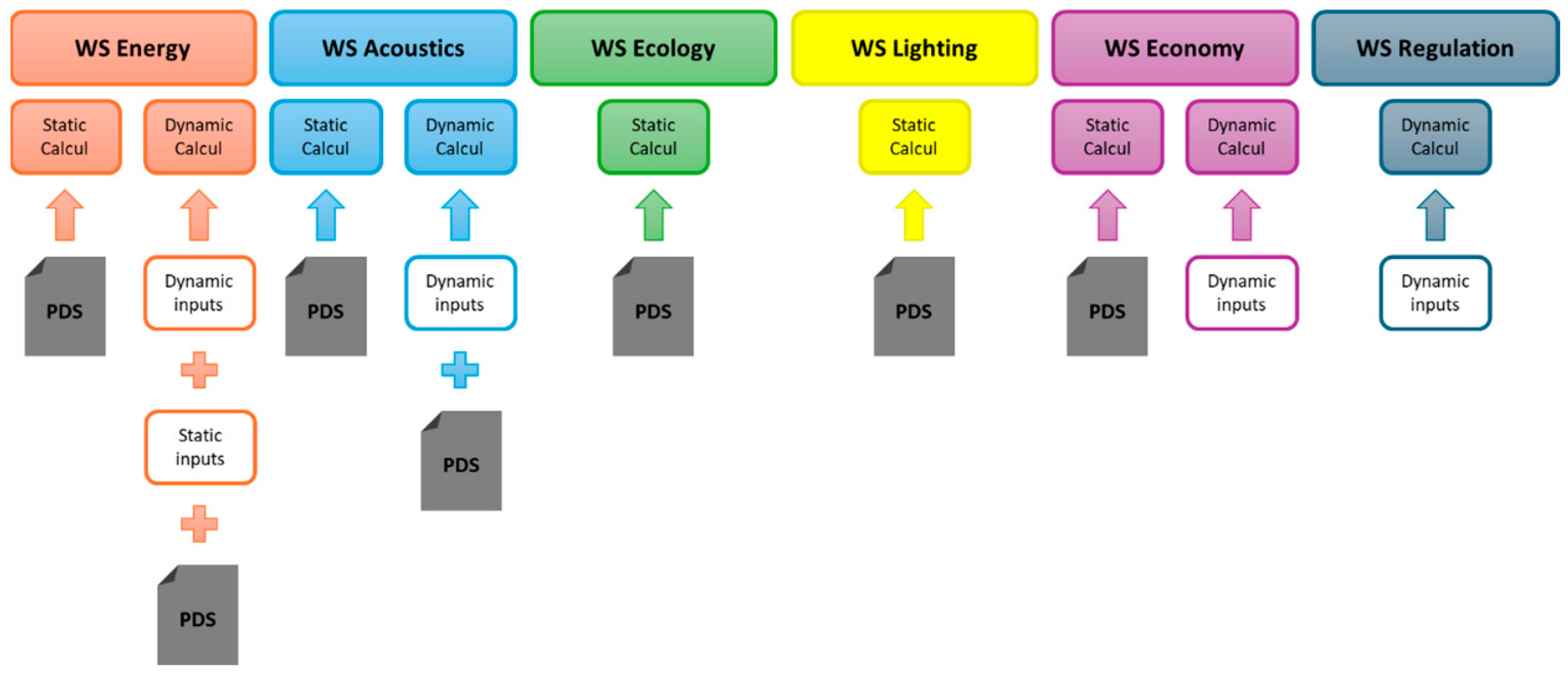
The appendix provides illustrative material describing how simulation, optimization, and decision-support services interact within the proposed service-oriented framework. The figures included in this appendix aim to clarify service roles and interaction patterns without introducing additional methodological elements.
Figure A2 illustrates the coupling architecture of the overall model and decision-support tools. Simulation services are coordinated through an orchestration layer, while optimization and expert-rule services operate as independent components interacting through structured data exchanges. The orchestration mechanism manages execution sequencing and data circulation without embedding domain-specific logic.
Figure A2. The coupling architecture of the overall model and decision support tools.
Applsci 16 06755 g0a2
Figure A3 presents an interaction bus organizing service exchanges across different design assistance tasks and specialized simulation tools. Domain-specific services, such as energy, acoustics, lighting, ecology, economics, and regulation, are accessed through web-service interfaces over a distributed environment. Higher-level services, including orchestration, optimization, and expert rules, operate independently from the underlying simulation tools.
Figure A3. Interaction bus of tasks and design phases used in the case study.
Applsci 16 06755 g0a3
Figure A4 focuses on the interaction pattern between optimization processes and domain-specific simulation services. It highlights the use of the Pivot DataSet (PDS) to coordinate static and dynamic inputs exchanged between services. The figure illustrates how multiple performance domains are evaluated within a unified workflow while preserving the autonomy of individual simulation services.
Figure A4. Trades Web Services Architecture.
Applsci 16 06755 g0a4
These figures are provided for illustration purposes only. They are not required to understand the methodological contributions or the evaluation results presented in the main paper, but they serve to clarify the architectural context of the proposed approach.

Appendix A.4. Illustrative Behavior of Waveform Relaxation in Service-Based Co-Simulation

This appendix provides pedagogical illustrations of the waveform relaxation method (WRM) to support the qualitative interpretation of the coupling behavior discussed in the main paper. The figures included here are schematic constructions based on the theoretical principles of waveform relaxation [27]; they are not generated from the COSIMPHI experimental data and do not represent measured residuals, measured convergence profiles, or measured error curves from the classroom case study. The actual iteration counts obtained in the COSIMPHI experiments (10 iterations for the one-day simulation and 13 iterations for the one-month simulation) are reported quantitatively in Table 5 of the main paper. The appendix material is therefore provided solely to support the conceptual understanding of the WRM process for readers unfamiliar with waveform-based coupling strategies.
Figure A5 illustrates the window-based waveform relaxation process over three successive time windows. The figure shows the evolution of waveform approximations across iterations and their convergence toward a reference solution. It highlights how interaction signals are progressively updated within each time window while preserving temporal continuity across windows.
Figure A5. Pedagogical illustration—not generated from COSIMPHI experimental data. Schematic illustration of the window-based waveform relaxation process over three successive time windows. The curves show the evolution of waveform approximations at iterations 1 and 2 and at convergence, together with a reference solution. The figure is provided for conceptual clarity and is based on the standard principles of waveform relaxation [27]; it does not represent convergence or residual measurements from the classroom case study.
Applsci 16 06755 g0a5
Figure A6 complements this illustration by distinguishing local, propagated, and global errors associated with the waveform relaxation process. The figure emphasizes how errors introduced within a given time window may propagate to subsequent windows and how successive iterations reduce the overall approximation error relative to the exact solution.
Figure A6. Pedagogical illustration—not generated from COSIMPHI experimental data. Schematic illustration of local, propagated, and global errors in a window-based waveform relaxation process. The exact solution is represented in black, while the WRM approximation is shown in red. Dashed lines indicate propagated errors across successive time windows, while arrows indicate error propagation between windows. The figure is provided for conceptual clarity and is based on the standard principles of waveform relaxation [27]; it does not represent measured error data from the classroom case study.
Applsci 16 06755 g0a6
These figures are included to clarify the qualitative behavior of waveform relaxation and to support the discussion on coupling performance presented in the main paper. They are not required to understand the implementation details or the quantitative evaluation results.

References

  1. International Energy Agency (IEA). Tracking Buildings 2023; IEA: Paris, France, 2023; Available online: https://www.iea.org/reports/tracking-buildings-2023 (accessed on 14 May 2026).
  2. Nejat, P.; Jomehzadeh, F.; Taheri, M.M.; Gohari, M.; Abd Majid, M.Z. A Global Review of Energy Consumption, CO2 Emissions and Policy in the Building Sector. Renew. Sustain. Energy Rev. 2015, 43, 843–862. [Google Scholar]
  3. Boje, C.; Guerriero, A.; Kubicki, S.; Rezgui, Y. Towards a Semantic Construction Digital Twin: Directions for Future Research. Autom. Constr. 2020, 114, 103179. [Google Scholar] [CrossRef]
  4. Khajavi, S.H.; Motlagh, N.H.; Jaribion, A.; Werner, L.C.; Holmstrom, J. Digital Twin: Vision, Benefits, Boundaries, and Creation for Buildings. IEEE Access 2019, 7, 147406–147419. [Google Scholar] [CrossRef]
  5. Hensen, J.L.M.; Lamberts, R. (Eds.) Building Performance Simulation for Design and Operation; Spon Press: London, UK, 2011. [Google Scholar]
  6. Crawley, D.B.; Hand, J.W.; Kummert, M.; Griffith, B.T. Contrasting the Capabilities of Building Energy Performance Simulation Programs. Build. Environ. 2008, 43, 661–673. [Google Scholar] [CrossRef]
  7. Wetter, M.; Zuo, W.; Nouidui, T.S.; Pang, X. Modelica Buildings Library. J. Build. Perform. Simul. 2014, 7, 253–270. [Google Scholar] [CrossRef]
  8. Lu, Q.; Parlikad, A.K.; Woodall, P.; Don Ranasinghe, G.; Xie, X.; Liang, Z.; Konstantinou, E.; Heaton, J.; Schooling, J. Developing a Digital Twin at Building and City Levels: Case Study of West Cambridge Campus. J. Manag. Eng. 2020, 36, 05020004. [Google Scholar] [CrossRef]
  9. Evins, R. A Review of Computational Optimisation Methods Applied to Sustainable Building Design. Renew. Sustain. Energy Rev. 2013, 22, 230–245. [Google Scholar] [CrossRef]
  10. ISO 16739-1:2024; Industry Foundation Classes (IFC) for Data Sharing in the Construction and Facility Management Industries—Part 1: Data Schema. ISO: Geneva, Switzerland, 2024.
  11. Pauwels, P.; Zhang, S.; Lee, Y.-C. Semantic Web Technologies in the AEC Industry: A Literature Overview. Autom. Constr. 2017, 73, 145–165. [Google Scholar] [CrossRef]
  12. Modelica Association. Modelica Language Specification; Version 3.6; Modelica Association: Linköping, Sweden, 2023; Available online: https://specification.modelica.org/maint/3.6/MLS.html (accessed on 12 June 2026).
  13. Fritzson, P. Principles of Object-Oriented Modeling and Simulation with Modelica 3.3: A Cyber-Physical Approach; Wiley-IEEE Press: Hoboken, NJ, USA, 2014; ISBN 978-1-118-85912-4. [Google Scholar]
  14. Wetter, M.; Benne, K.; Tummescheit, H.; Winther, C. Spawn: Coupling Modelica Buildings Library and EnergyPlus to Enable New Energy System and Control Applications. J. Build. Perform. Simul. 2024, 17, 274–292. [Google Scholar] [CrossRef]
  15. Blochwitz, T.; Otter, M.; Akesson, J.; Arnold, M.; Clauss, C.; Elmqvist, H.; Friedrich, M.; Junghanns, A.; Mauss, J.; Neumerkel, D.; et al. Functional Mockup Interface 2.0: The Standard for Tool Independent Exchange of Simulation Models; The Modelica Association: Linköping, Sweden, 2012; pp. 173–184. [Google Scholar] [CrossRef]
  16. Nouidui, T.S.; Wetter, M.; Zuo, W. Functional Mock-up Unit for Co-Simulation Import in EnergyPlus. J. Build. Perform. Simul. 2014, 7, 192–202. [Google Scholar] [CrossRef]
  17. Chamari, L.; Petrova, E.; Pauwels, P. An End-to-End Implementation of a Service-Oriented Architecture for Data-Driven Smart Buildings. IEEE Access 2023, 11, 117261–117281. [Google Scholar] [CrossRef]
  18. Zhang, K.; Blum, D.; Cheng, H.; Paliaga, G.; Wetter, M.; Granderson, J. Estimating ASHRAE Guideline 36 Energy Savings for Multi-Zone Variable Air Volume Systems Using Spawn of EnergyPlus. J. Build. Perform. Simul. 2022, 15, 215–236. [Google Scholar] [CrossRef]
  19. Modelica Association. Functional Mock-Up Interface for Model Exchange and Co-Simulation; Version 3.0; Modelica Association Project FMI: Linköping, Sweden, 2022. [Google Scholar]
  20. Palmintier, B.; Krishnamurthy, D.; Top, P.; Smith, S.; Daily, J.; Fuller, J. Design of the HELICS High-Performance Transmission-Distribution-Communication-Market Co-Simulation Framework. In Proceedings of the 2017 Workshop on Modeling and Simulation of Cyber-Physical Energy Systems (MSCPES); IEEE: Pittsburgh, PA, USA, 2017; pp. 1–6. [Google Scholar] [CrossRef]
  21. Raad, A.; Reinbold, V.; Delinchant, B.; Wurtz, F. Energy Building Co-Simulation Based on the WRM Algorithm for Efficient Simulation over FMU Components of Web Services. In Proceedings of the Building Simulation Conference, Hyderabad, India, 7–9 December 2015; Available online: https://hal.science/hal-01245073 (accessed on 14 May 2026).
  22. Cellier, F.E.; Greifeneder, J. Continuous System Modeling; Springer: New York, NY, USA, 1991. [Google Scholar]
  23. Raad, A.; Reinbold, V.; Delinchant, B.; Wurtz, F. FMU Software Component Orchestration Strategies for Co-Simulation of Building Energy Systems. In Proceedings of the 2015 Third International Conference on Technological Advances in Electrical, Electronics and Computer Engineering (TAEECE); IEEE: Beirut, Lebanon, 2015; pp. 7–11. [Google Scholar] [CrossRef]
  24. Gomes, C.; Thule, C.; Broman, D.; Larsen, P.G.; Vangheluwe, H. Co-Simulation: A Survey. ACM Comput. Surv. 2019, 51, 1–33. [Google Scholar] [CrossRef]
  25. Sacks, R.; Eastman, C.M.; Lee, G.; Teicholz, P.M. BIM Handbook: A Guide to Building Information Modeling for Owners, Managers, Designers, Engineers and Contractors, 3rd ed.; Wiley: Hoboken, NJ, USA, 2018; ISBN 978-1-119-28753-7. [Google Scholar]
  26. Kübler, R.; Schiehlen, W. Two Methods of Simulator Coupling. Math. Comput. Model. Dyn. Syst. 2000, 6, 93–113. [Google Scholar] [CrossRef]
  27. Lelarasmee, E.; Ruehli, A.E.; Sangiovanni-Vincentelli, A.L. The Waveform Relaxation Method for Time-Domain Analysis of Large Scale Integrated Circuits. IEEE Trans. Comput.-Aided Des. Integr. Circuits Syst. 1982, 1, 131–145. [Google Scholar] [CrossRef]
Figure 1. Taxonomy of building simulation models based on key modeling dimensions.
Applsci 16 06755 g001
Figure 2. Illustration of the three levels of interoperability in the building sector. BIM: Building Information Modeling; ODE: Ordinary Differential Equation.
Applsci 16 06755 g002
Figure 3. Evolution from model-level and code-level integration toward service-level interoperability. (a) Hierarchical integration levels, consistent with the abstraction hierarchy discussed in [24]. Colors distinguish interoperability levels, and arrows indicate the conceptual transition toward service-level coordination; (b) Conceptual positioning of interoperability levels with respect to coupling strength, execution flexibility, and interaction granularity.
Applsci 16 06755 g003
Figure 4. Service-based data exchange between autonomous simulation programs through web-service interfaces.
Applsci 16 06755 g004
Figure 5. Principle of waveform relaxation for service-based co-simulation, adapted from [21]. Arrows indicate the iterative exchange of interaction waveforms between coupled services; colors distinguish successive WRM iterations.
Applsci 16 06755 g005
Figure 6. Service-oriented co-simulation architecture illustrating the interaction between simulation services, orchestration, and data exchange through the PDS. Arrows indicate data exchanges between services and the orchestration layer.
Applsci 16 06755 g006
Figure 7. Coupled thermal–acoustic co-simulation over a representative summer week. Shaded areas indicate occupied periods from 8 a.m. to 6 p.m. (a) Outdoor and indoor temperatures, temperature setpoint, and window-opening command. (b) Outdoor and indoor noise levels and indoor comfort index used in the orchestration-level regulation logic.
Applsci 16 06755 g007aApplsci 16 06755 g007b
Table 1. Comparison of data-, code-, and service-level interoperability approaches in building simulation.
CriterionData-Level (IFC)Code-Level (FMI)Service-Level (Proposed)
Tool autonomy
Dynamic coupling
Distributed execution∼ overhead
No internal access required
Flexible coupling strategy∼ limited
No tool modification required∼ FMU export
✓: supported; ✗: not supported; ∼: partially supported depending on implementation constraints.
Table 2. Qualitative positioning of FMI, HELICS, and the proposed service-level approach for distributed building-performance co-simulation.
CriterionFMI-Oriented
Integration
HELICS-Like
Federation
Service-Level
Approach Proposed Here
Integration unitFMU or model component exposed through standardized FMI interfaces.Federate connected to a broker-mediated co-simulation federation.Autonomous simulation service exposed through HTTP/web-service interfaces.
Required adaptation of existing toolsRequires FMU export, wrapping, or access to model interfaces.Requires implementation of a HELICS federate and integration with the broker infrastructure.Requires only service endpoints and orchestration-level data mapping; internal model code can remain unchanged.
Coupling controlHandled through master algorithms and communication points at the component level (FMI 2.x); FMI 3.0 extends this with clock-based event coordination for asynchronous scenarios.Handled through broker-mediated time coordination and message exchange.Handled explicitly by the orchestrator, which can switch between chaining and the waveform relaxation method (WRM) strategies.
Typical application contextComponent-based model exchange or co-simulation when FMUs are available.Large-scale cyber-physical energy-system federation with many communicating federates.Early-stage multi-performance building workflows involving autonomous, heterogeneous, or proprietary tools.
Main strengthStandardized interface for model exchange and co-simulation; broad support in simulation environments.Scalable coordination of distributed federates; suitable for large cyber-physical energy-system studies.Low-intrusion integration of existing domain tools preserves tool autonomy and enables orchestration-level coupling.
Main limitation in the COSIMPHI contextNot all professional tools can be exported or exposed as FMUs.Requires deeper framework-specific integration than is available for some legacy building tools.Less standardized than FMI/HELICS and requires careful design of service contracts and orchestration logic.
Network deploymentDepends on the implementation; standard ports can be used in server-based configurations.Non-standard Transmission Control Protocol (TCP) ports; requires explicit firewall and network configuration.HTTP/HTTPS communication through standard web ports (80/443), which are typically open by default on institutional networks, facilitates deployment in distributed environments.
Table 3. Domain tools involved in the COSIMPHI demonstrator.
DomainToolDeveloper/OwnerRole in COSIMPHI Workflow
Energy/thermal comfortCOMEThCSTB/DEEDynamic energy simulation, summer comfort assessment, air transfers, HVAC behavior, occupancy-related loads
Lighting/visual comfortPHANIECSTBDaylighting simulation, artificial lighting control, solar protection management, and visual comfort assessment
AcousticsACOUBATCSTBPrediction of indoor acoustic performance, airborne noise, impact noise, equipment noise, and façade-opening effects
Environmental assessmentELODIECSTBBuilding lifecycle assessment based on components, energy, water, construction site, and transport contributors
Global costCost toolUniversity of La RochelleGlobal-cost assessment according to life-cycle-costing principles
Table 4. Co-simulation time of the Energy and Acoustics web-service (step of one hour). WS: web services.
Thermal
Regulation
Thermal + Acoustic Regulation Acoustic
(Occupied Hours)
One weekCo-simulation time4 min4 min 12 s2 min 54 s
Nb. of exchanges via WS504672308
One dayCo-simulation time34 s36 s25 s
Nb. of exchanges via WS729644
Note: Values represent session-average observations from the COSIMPHI experimental campaign (Dell workstation, Intel Core i5, G2Elab LAN). Individual run logs are no longer available; exact repeatability quantification was therefore not performed. Comparisons are indicative and should not be interpreted as hardware-independent benchmarks.
Table 5. Comparison of co-simulation times for 1 day and 1 month, conducted both locally and over the Internet. WS: web services.
Simulation Period1 Day1 Month
Coupling MethodWRMChainingWRMChaining
Number of Iterations1014401343,145
Local Co-simulationCo-simulation time6 s0.5 s240 s15 s
Iteration time0.6 s0.35 ms18.4 s0.35 ms
WS Co-simulationCo-simulation time11.2 s720 s525 s21,600 s
Iteration time
(computation + transfer)
1.12 s0.5 s19.4 s0.5 s
Note: Values represent session-average observations from the COSIMPHI experimental campaign; individual run logs are no longer available. The primary comparison basis is the synchronization iteration count and the number of web-service exchanges, which are structurally determined by the coupling strategy configuration, whereas wall-clock times are indicative only.
Disclaimer/Publisher’s Note: The statements, opinions and data contained in all publications are solely those of the individual author(s) and contributor(s) and not of MDPI and/or the editor(s). MDPI and/or the editor(s) disclaim responsibility for any injury to people or property resulting from any ideas, methods, instructions or products referred to in the content.