1. Introduction
With the development of the sharing economy, shared bicycles have been incorporated into the urban green transportation system. However, due to the above reasons, the company is losing money. Disordered parking occupies urban public areas; regional supply–demand imbalance results in inefficient use of resources, and manual operation and maintenance are relatively high in cost. These reasons prevent the normal operation of the company. Therefore, in recent years, both in academia and industry, many people have started to explore ways to improve the management efficiency of shared bicycles using technology [
1].
At present, the collection and transportation of shared bicycles still mainly depend on manual work. Shared bicycles are widely scattered and frequently relocated, making the traditional manual collection method inefficient and incapable of adapting to the spatial distribution across various regions and time-varying demand patterns [
2]. Most existing intelligent grabbing systems for urban traffic vehicles adopt a single target-detection model for bicycle recognition, with their decision-making layers controlled by conventional PID scheduling logic, which delivers poor robustness when dealing with complex sidewalk occlusions and stacked bicycles in diverse postures. Hybrid neural network–Transformer architectures integrate multi-scale image features and environmental time-series data to realize multi-objective classification and scene-adaptive decision-making. Chechkin et al. [
3] proposed a hybrid neural network–Transformer framework that achieves accurate target classification in complex scenes through hierarchical feature extraction. Its multi-modal feature fusion concept can be transferred to the recognition of shared bicycles from multiple viewing angles and stacked poses, effectively improving the stability of bicycle grabbing and identification on complicated urban roadways [
3]. This hybrid AI architecture boasts prominent advantages in dynamic visual inspection and target classification under multi-interference environments, and can provide theoretical support for the integrated design of the YOLOv8 vision module and autonomous scheduling decision module in this system. In addition, long-term outdoor exposure increases the risk of bicycle failures, which further raises operation and maintenance costs. To solve the above problems, this paper proposes an intelligent collection and transportation system for shared bicycles equipped with a supporting multi-modal intelligent visual decision system, filling the application gap of existing research in scenarios with coordinated operation of multiple devices. The technical objectives are set as follows:
- i.
Accurate Positioning and Fast Dispatch: Based on vision recognition and positioning technology, quickly locate bicycles and flexibly redistribute them to relieve regional supply–demand imbalances.
- ii.
Cost Reduction and Efficiency Improvement by Automation: Replace manual operations with multi-agent collaborative tasks [
3]. Working with the above two measures, reduce maintenance costs and extend the life cycle of the bicycles.
- iii.
Improve User Experience (UX) by adding features such as car cleaning and fault detection, increasing the convenience and leisure factor of the shared-bike service for users.
In summary, the construction of the system framework is the starting point of this research. At present, the collection and transportation of shared bicycles rely heavily on manual labor. The scattered and mobile distribution of vehicles and harsh outdoor working conditions increase operation and maintenance costs. Moreover, existing hybrid AI multi-modal visual detection schemes can hardly realize linkage and coordination with grabbing, horizontal shifting and transporting mechanisms, resulting in defects such as separation between perception and execution information and delayed decision-making in dynamic scenarios, as shown in
Table 1.
To address the core problems arising during the operation of shared bicycles, including low manual collection efficiency, high failure rates of vehicles exposed outdoors, and poor compatibility between traditional visual inspection and automated equipment, this paper develops a prototype-integrated intelligent collection and distribution system for shared bicycles. The system consists of a vehicle collection system made up of clamping devices, adaptive devices, all-directional transverse moving devices and mobile base devices, as well as a transfer system integrating fixed storage devices, cleaning and detection devices and a mobile base. A supporting multi-modal intelligent visual decision module is developed, which combines depth vision and multi-modal algorithms to realize bicycle identification, positioning and fault detection, and realizes linked scheduling with all executive mechanisms of the equipment. Subsequently, simulation analysis and physical prototype experiments will be carried out to fully verify the operational feasibility of the complete equipment and the visual decision-making system, providing comprehensive theoretical support and engineering technical references for the full-process intelligent operation and maintenance of shared bicycles. This integrated automatic collection and transportation scheme can drastically cut manual maintenance costs and effectively tackle the difficulties in bicycle recycling and sorting under outdoor environments, contributing to the overall improvement of digital organization and refined management of the urban slow-traffic system. The remainder of this paper is structured as follows.
Section 2 presents the overall design of the shared bicycle collection and transfer system. Starting from the actual operation demands of urban shared bicycle maintenance, the overall mechanical layout, multi-posture grabbing mechanism, automatic transfer unit and fixed-point placement module of the robot are elaborated on in detail. The system workflow, drive scheme and control logic are also illustrated to lay a complete hardware design foundation for subsequent structural verification and prototype development.
Section 3 conducts finite-element analysis on the key load-bearing and grabbing components of the collection and transfer system. Static mechanical simulation is carried out to obtain the stress, strain and deformation distribution of core parts under typical working conditions. Structural weak points are identified, and corresponding structural optimization suggestions are proposed to guarantee the mechanical safety and structural stability of the robot during long-term continuous operation.
Section 4 describes the prototype fabrication, assembly and comprehensive experimental tests of the collection and transfer robot. A physical prototype and a simulated urban road test platform are constructed. Multiple groups of functional tests, efficiency comparison tests and extreme working condition verification experiments are implemented. Test data are quantitatively analyzed to verify the actual operation efficiency, grabbing adaptability and environmental adaptability of the integrated robot system.
Section 5 summarizes the full research work. The core innovations and engineering advantages of the intelligent shared bicycle collection robot are concluded. The inherent technical limitations of the current prototype are objectively discussed, and targeted improvement strategies and future research directions for engineering promotion and multi-scenario application are put forward.
2. Overall Design of the Collection and Redistribution System
The complete collection and redistribution workflow is defined as follows: visual perception, bicycle localization and posture recognition, adaptive gripper-spacing adjustment, wheel clamping, lifting and 90° posture correction, transfer-robot positioning, fixing and storage, cleaning and inspection, and redistribution to a designated parking area. This workflow links the perception output directly to the mechanical gripping, lifting, transfer, and maintenance modules, so that the system can be reproduced as an integrated collection–transfer process rather than as isolated mechanisms.
The originality of this design is not the independent use of YOLOv8, Mecanum wheels, or a conventional gripper. The contribution is the integrated mechanical layout for multi-posture shared bicycles: an adaptive wheel-clamping mechanism, a coordinated lifting and posture-adjustment mechanism, a transfer fixing-storage mechanism, a cleaning-inspection module, and a vision-guided localization flow that provides the geometric inputs required by these mechanisms.
Robots need to move in an urban area, randomly find a parked shared bicycle, pick it up, and deliver it to an area with a higher demand for bicycles. The above system can increase the use of bicycles, support enterprise operations, and promote low-carbon travel. However, in practice, shared bicycles are often parked in an irregular manner and may be mixed with bicycles from different brands. The above conditions have relatively high demands for the collection and redistribution mechanism [
4]. Based on the above, the shared bicycle collection and redistribution system in this paper should have the following features:
- i.
Grasping Ability: The system needs to be able to stably hold bicycles in all directions and even when they are overturned.
- ii.
Mobility: The system should have all-wheel drive to be able to drive on uneven ground and irregular bicycle locations.
- iii.
Perception and recognition: Locate and identify the shared bicycles in the system, and be able to recognize various kinds of bicycles.
- iv.
Autonomous Operation: In difficult conditions, the system is to operate alone for both collection and transfer.
- v.
Transport capacity: The system should be able to transport bicycles collected from various places and in different numbers.
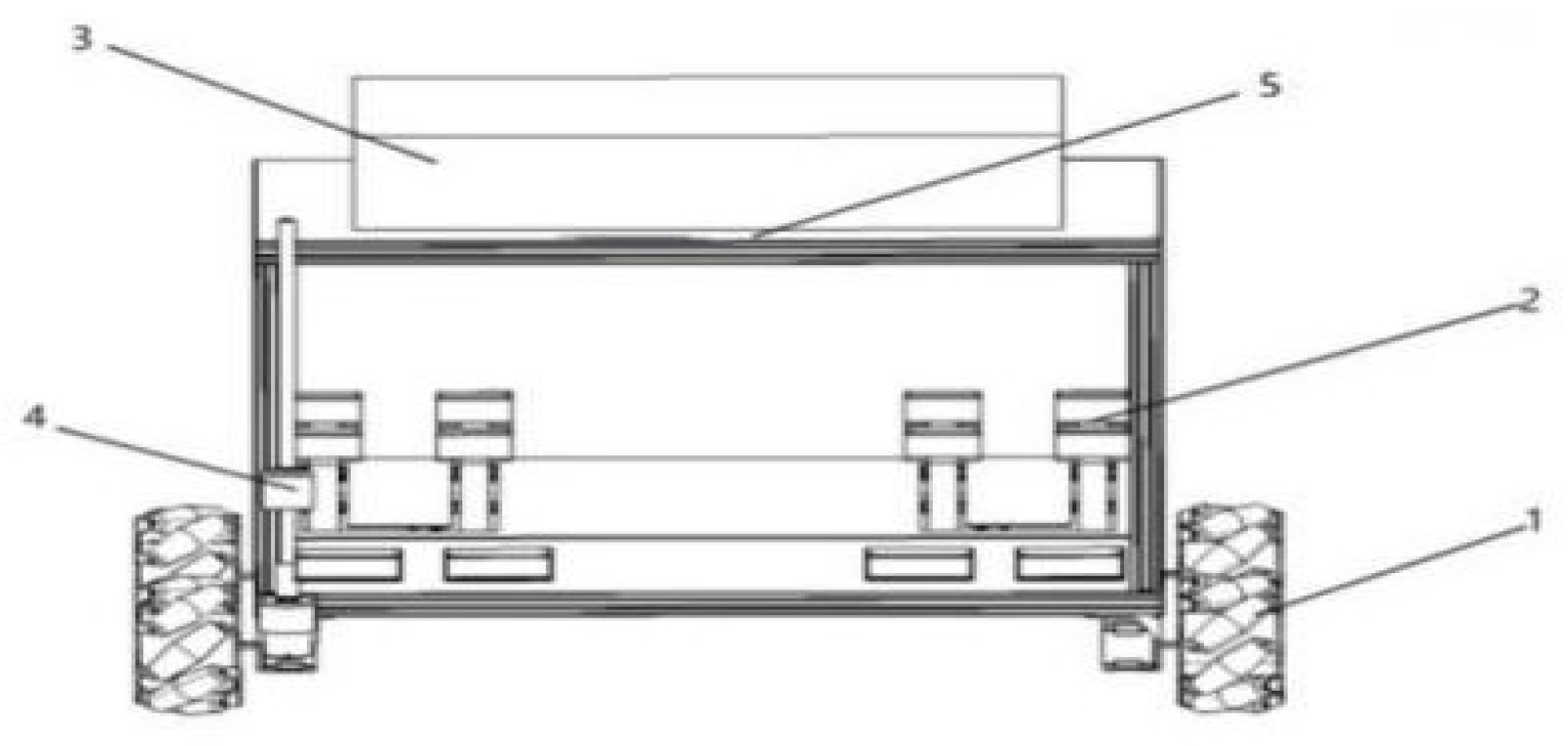
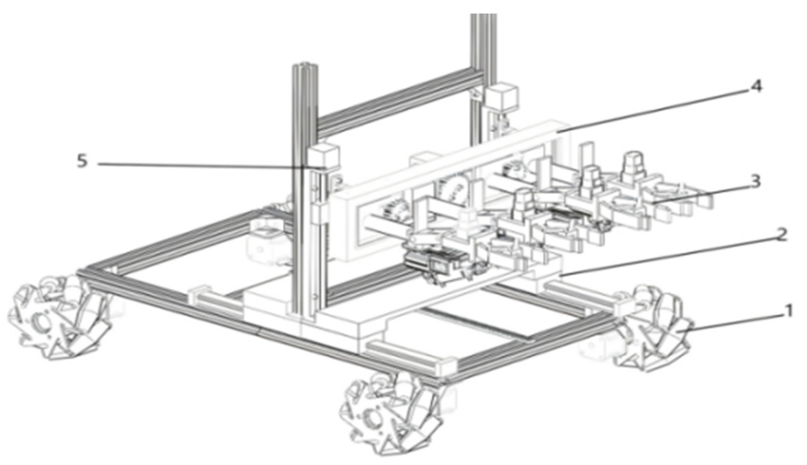
This paper proposes a design scheme for a shared bicycle collection and transportation system, as shown in
Figure 1 and
Figure 2. A mechanical gripper can be used to perform a 90-degree vertical bend and maintain the position of a bicycle by means of thrust from an air pump and a rack mechanism. The four mechanical grippers in the adaptive device are for four sizes of bicycle wheels. Research has been carried out on the impact of the grasping process on the mechanical structure and the strength of relevant mechanisms to assess whether the robot can be built. The main parameters of the robot are as shown in
Table 2.
The two types of robots in the system are a cluster robot and a mobile platform. The two mechanical grippers are arranged symmetrically on the left and right sides (two on each side) and the robot utilizes an adjustment device that can adapt to the size of the bicycle to be held, a multi-mechanism coordinated motion device for omnidirectional movement adjustment, and a mobile base that uses Mecanum wheels. The four units of the transfer robot are a common bicycle-fixing device, a cleaning device, an inspection device and a mobile base. The Robot system is able to collect, transport, organize and clean shared bicycles.
The two parts of the shared bicycle collection and transfer system are a collection robot and a transfer robot. The particular structure is as follows:
The collection robot is a Mecanum-wheel mobile platform. It is a fully adjustable structure that has longitudinal, vertical and horizontal movement mechanisms [
5]. In addition, a counter-traversal mechanism for the gripping device, rotary joints, and mechanical grippers can all be used by the robot for different collection tasks.
The transfer robot is also a Mecanum-wheel-driven base. Add a gripper and a translational device to hold and move bicycles inwards. It is a four-spray-hole cleaning device that also has an infrared-detector damage-detection function.
2.1. Gripping Device
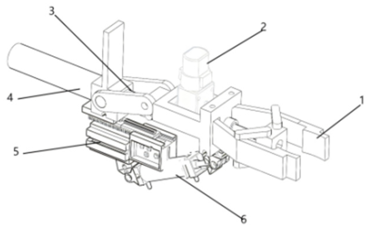
The structure of the gripping device on the collection robot is shown in
Figure 3. A motor drives a mechanical gripper to clamp and release.
A rotary joint structure is used in the grip device to adjust the position of the collection robot for different orientations of shared bicycles. A steering gear that drives the joint is employed here. A telescopic motion of the geared rod is used to achieve a 90-degree joint rotation in the mechanism.
A dropped shared bicycle is detected, and then a rotary joint rotates the gripper by 90 degrees to grasp the bicycle in a suitable position. A vertical-lifting device will raise the bicycle. After raising it, a 90-degree rotation occurs again, and at the same time, the collection device rotates to secure the bicycle stably.
To avoid slipping of the bicycle during lifting, the friction force provided by the gripper must be larger than the weight of the bicycle (plus acceleration).
where F_grip is the minimum clamping force supplied by each gripper (N), m is the bicycle mass (kg), g is gravitational acceleration (9.81 m/s
2), a is the vertical lifting acceleration (m/s
2), SF is the safety factor (-), and μ is the friction coefficient between the rubber pad and the wheel/frame contact surface (-).
2.2. Adaptive Device
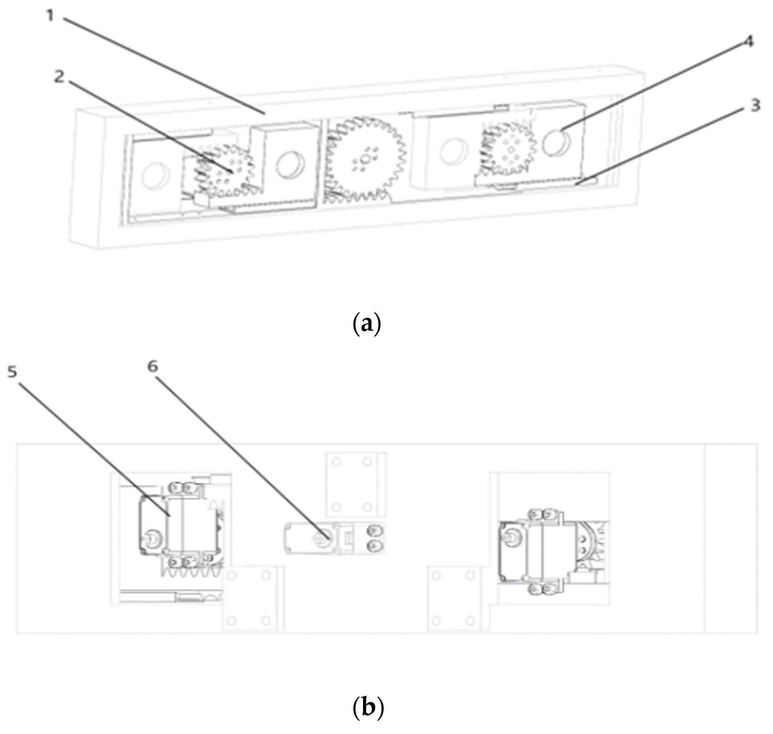
The adaptive mode of the robot collector is shown in
Figure 4. It consists of two sets of different reverse transverse mechanisms, and each set has two rack blocks and one gear; it is driven by a servo motor to move the rack blocks and thus adjust the distance between the grippers. A servo is used to adjust the distance of the two grippers according to the different sizes of the bicycles and thus fit many different bicycle sizes. The robot can hold various bicycles; for example, it will move other bicycles that are obstructing the path to put the target bicycle in a good place and organize them neatly. It can also pick up and move the target bicycle autonomously, and there will be no harm to any other bicycles during this process.
The torque supplied by the motor needs to overcome the resistance of the rack and move it:
where T_motor is the required motor torque (N·m), F_total is the total rack resistance including sliding friction and bicycle-contact resistance (N), D_gear is the pitch diameter of the drive gear (m), and η is the transmission efficiency (-).
2.3. Omnidirectional Transverse Mechanism
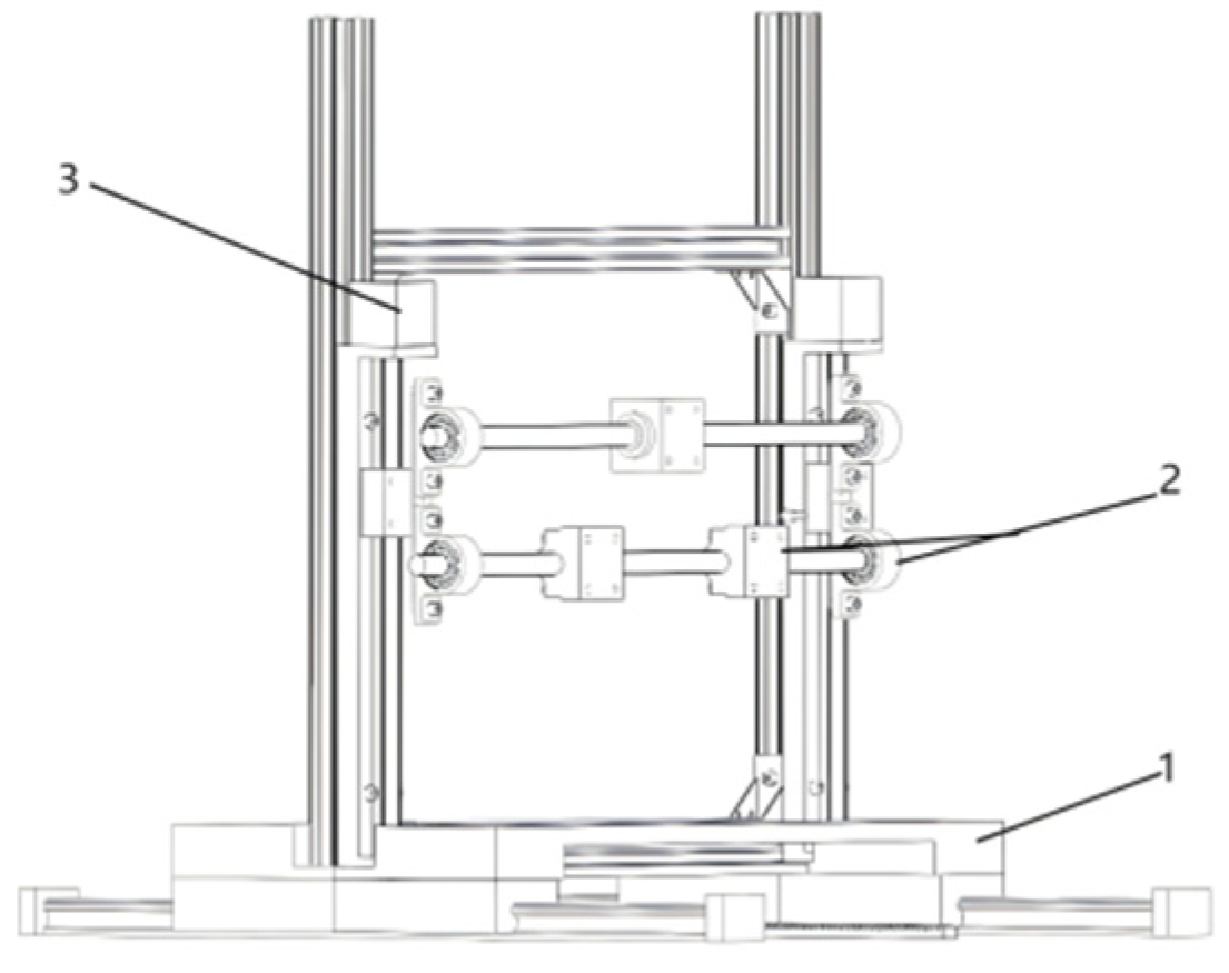
The structure of the omnidirectional transverse mechanism for the collection robot is shown in
Figure 5. The left–right transverse mechanism consists of a lead screw and a slide rod, and forward and reverse rotation of the motor can be used to achieve left–right transverse movement. A lead screw and a slide rail are used to construct the up–down transverse mechanism [
6], and it can be driven by a motor to move vertically. The rack and pinion mechanism of the forward–backward drive consists of a rack, a sliding rail and a slider [
7]. Together, these three ways form the all-directional transverse structure of a mechanical gripper and can move in any direction for the collection robot.
Primarily to counteract gravity, the required lifting torque for the lead screw should be determined.
where T_lift is the required lifting motor torque (N·m), F is the total vertical load applied to the lead screw (N), p is the screw lead (m/rev), and η is the screw-drive efficiency (-).
2.4. Mobile Base
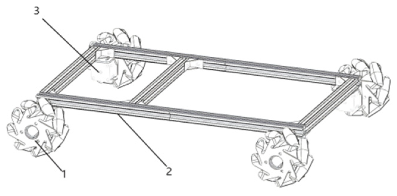
The mobile bases of the collection robot and the transfer robot are shown in
Figure 6, and Mecanum wheels are used to achieve omnidirectional movement; both robots are thus more maneuverable [
8].
After obtaining the wheel linear velocity Vi, it needs to be converted into the motor rotational speed ni:
where n_i is the rotational speed of the i-th drive motor (r/min), V_i is the linear velocity command of the corresponding wheel (m/s), and R is the wheel radius (m).
2.5. Fixed Storage Device
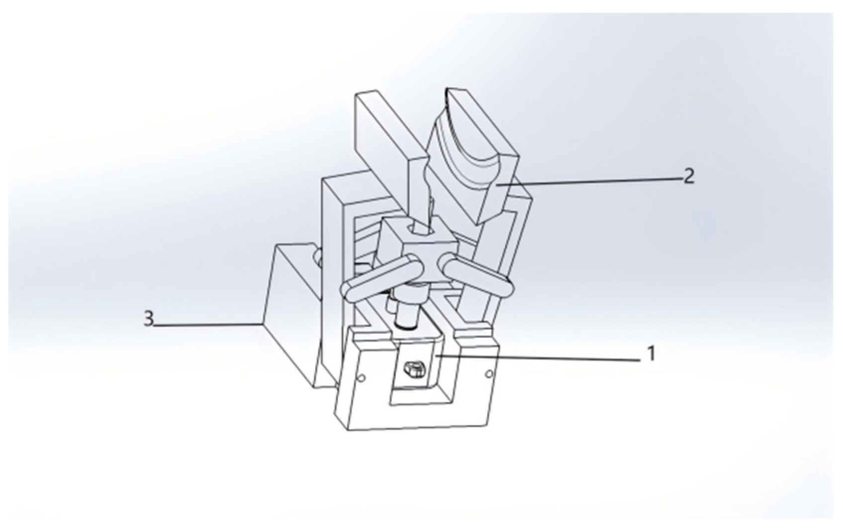
The structure of the fixed storage device in the transfer robot is shown in
Figure 7. This device has a mechanical gripper and several sets of translation devices.
When the collection robot places the bicycle above the fixed device, photoelectric sensors [
9] inside the transfer robot sense that there is a bicycle. When the bicycle reaches a certain position, a signal is emitted by the sensor to stop the collection robots. Then, the robotic arm lowers the bicycle to the preset height of the wheels, and at that moment, the photoelectric sensor also sends out a signal.
This signal stops the lower part of the collection robot. At the same time, the motor of the mechanical gripper in the fixing device of the transfer robot is turned on to clamp and fix the bicycle. Each fixing device is attached to a translation device. After the first gripper takes a bicycle, the corresponding translation unit moves into the storage position. Then the next fixing device will move to the working position for the following collection cycle. Thus, the storage space for the transfer robot will be more space-efficiently used.
The sensor response speed needs to be in line with the motion. The time condition is as follows:
where T_response is the sensor response time (s), S_safe is the reserved safety margin distance along the descending direction (mm), and V_down is the end-effector descent speed (mm/s). The units are converted consistently when the response time is specified in milliseconds.
2.6. Cleaning and Inspection Device
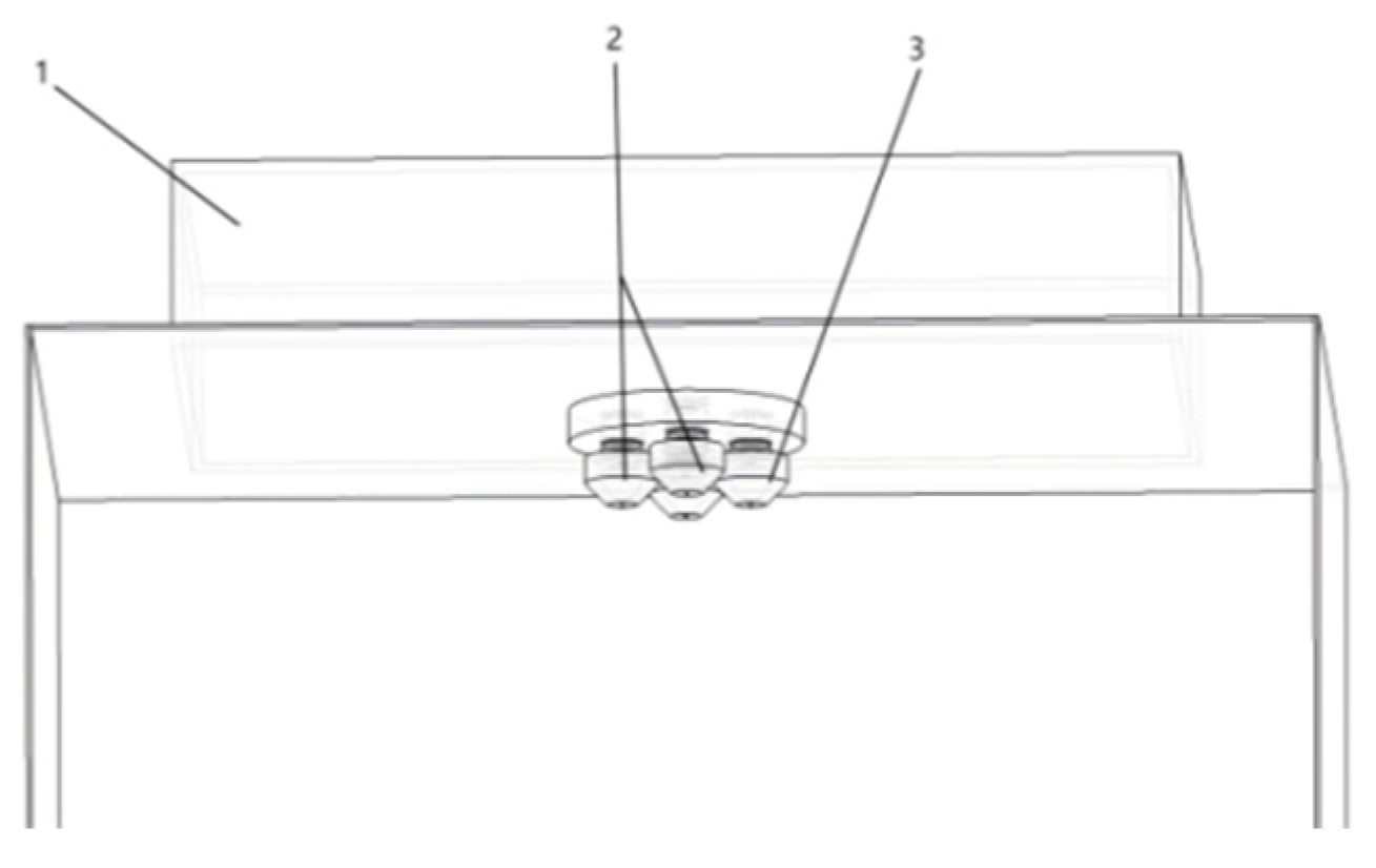
The cleaning device is shown in
Figure 8. It contains four micro high-pressure water jets and two servo motors [
10]. The two motors adjust the nozzle pitch and yaw so that the water jet can cover the frame, wheels, saddle, and handlebar regions during the transfer process.
The inspection device is also shown in
Figure 8. Infrared scanners are installed on both sides to conduct preliminary inspection of key components, including the chain, handlebars, and saddle. When an abnormal component is detected, a signal is sent to the collection robot and the damaged bicycle is placed in the designated fault-storage cart for later maintenance [
11].
This integrated cleaning and inspection arrangement improves maintenance convenience, reduces the frequency of manual preliminary checks, and helps extend the service life of shared bicycles.
The two servo motors are used for pitch and yaw adjustment of the nozzle so that the water jet scans the target surface around the bicycle.
where x, y, and z are the coordinates of the nozzle target point (mm), l is the distance from the nozzle outlet to the rotation center (mm), θ is the pitch servo angle (°), φ is the yaw servo angle (°), and H_b is the mounting height of the nozzle base (mm).
Control Logic: Through the coordinated interpolation of θ and ϕ, the water jet achieves a “scanning” rinse of the bicycle frame and wheels, effectively eliminating blind spots.
where F_j is the water-jet impact force (N), ρ is water density (kg/m
3), Q is the volumetric flow rate (m
3/s), and V is the jet velocity at the nozzle outlet (m/s).
where Q is the required cleaning flow rate (m
3/s), A_b is the estimated washable bicycle surface area (m
2), h is the target average water-film thickness (m), t_c is the effective cleaning time (s), and η_c is the cleaning coverage efficiency (-).
2.7. Visual Perception and Real-Time Computing
2.7.1. Dataset Construction and Annotation
To support bicycle localization in the prototype collection workflow, an implementation dataset of 6200 images was constructed from campus roadsides, parking areas, laboratory scale-model tests, and extracted video frames. The scenes include upright, side-fallen, inclined, partially occluded, mixed-brand, overlapping, and low-light parking conditions. The training, validation, and test sets were divided at 70%, 20%, and 10%, respectively. The annotated categories were bicycle body, front wheel, rear wheel, handlebar, saddle, and damaged or abnormal component. The dataset was used to provide reproducible perception input for the mechanical system rather than to claim a new detection theory. The basic dataset parameters are summarized in
Table 3.
2.7.2. YOLOv8 Training and Deployment Settings
The detector adopted a YOLOv8s configuration with 640 × 640 input resolution, batch size of 16, 150 training epochs, AdamW optimizer, an initial learning rate of 0.001, cosine learning-rate decay, and early stopping when validation mAP did not improve for 25 epochs. Data augmentation included random scaling, HSV perturbation, horizontal flipping, Mosaic augmentation in the early training stage, and random local occlusion. Training was performed on a workstation equipped with an RTX 3060-class GPU, while deployment tests used an edge computer with a GPU computing capability comparable to Jetson Orin NX or an x86 industrial computer with a compact CUDA GPU. The training and deployment settings are listed in
Table 4.
2.7.3. Detection Accuracy and Scope Boundary
On the 620-image held-out test set, the trained detector achieved a precision of 96.3%, recall of 94.7%, mAP@0.5 of 97.1%, and mAP@0.5:0.95 of 82.3%. Under approximately 30% partial occlusion, the bicycle-body AP@0.5 decreased to about 92%, but the wheel-region output still provided sufficient position input for adaptive gripper-spacing selection. Detailed YOLOv8 improvement, self-built dataset optimization, ablation tests, sensor-fusion experiments, and multi-model horizontal comparison have been completed as a separate visual-algorithm study; they are not repeated here to avoid departing from the mechanical-structure and mechanics-verification focus of this article. A compact engineering comparison is provided in
Table 5 to show why YOLOv8s was used in the prototype.
2.7.4. Real-Time Computing Cycle
The real-time processing sequence includes image acquisition, preprocessing, model inference, post-processing, coordinate transformation, control decision, and actuator command transmission. In the prototype test environment, image acquisition required 25–35 ms, preprocessing 5–8 ms, inference 28–35 ms, post-processing and coordinate transformation 8–12 ms, control decision 6–10 ms, and command transmission less than 5 ms. The end-to-end perception-control cycle was therefore approximately 80–105 ms, which is shorter than the 0.3 s recognition-response requirement and much shorter than the mechanical gripping and lifting cycle. The visual module outputs bicycle center, wheel centers, posture category, and abnormal-part flags to the collection controller.
2.8. Autonomous Operation Framework and Implementation Boundary
The autonomous operation framework is defined at the system-integration level. Outdoor localization can be implemented by GNSS/RTK, wheel odometry, and IMU fusion in open areas, while short-range visual markers or local SLAM can assist positioning in dense parking zones [
12,
13,
14]. Global routing is generated from bicycle-demand regions and service-road constraints, and local motion is executed at low speed by the Mecanum-wheel base using obstacle distance and camera perception as safety inputs.
Obstacle avoidance follows a conservative stop-yield strategy. Static obstacles are bypassed only when the local free space is sufficient; for pedestrians, vehicles, and other dynamic objects, the robot slows down or stops and waits for clearance. Multi-robot scheduling is treated as a task-assignment boundary condition: a central platform can allocate collection robots and transfer robots according to distance, bicycle density, battery level, and remaining storage capacity, but detailed fleet-optimization algorithms are outside the present mechanical-design study.
Therefore, the current work verifies the integrated mechanism and prototype-level collection–transfer process. Full outdoor autonomous driving, dense mixed-traffic interaction, and long-duration fleet scheduling require subsequent full-scale field tests and are regarded as future work.
3. Finite-Element Analysis of the Collection and Transfer System
Under automatic clamping, lifting and continuous transfer, the shared bicycle collection and transfer system are subjected to many types of coupled loads in various directions. Therefore, the structural strength and rigidity of the components need to ensure high precision and stability during use. If there is a stress concentration or large-scale deformation, then clamping failure, mechanism jamming, or position error will occur in the system, and it will not be reliable. Therefore, finite-element static analysis will be used to determine if the stiffness and load-bearing capacity of the structure meet the design requirements under the actual load. The analysis can also identify weak links in the prototype earlier.
Therefore, a baseline static finite-element simulation and a preliminary quasi-dynamic load-case assessment were carried out for the overall system. A three-dimensional model was built, the material properties and boundary conditions were defined, and stress and deformation responses were obtained under representative operating loads. The von Mises equivalent stress criterion and total displacement results were used to evaluate whether the structural feasibility of the proposed design was satisfied at the prototype engineering stage.
The analysis in this section should be understood as a prototype-level engineering assessment. It retains the original static finite-element result as the baseline and adds acceleration, braking, lateral eccentric-load, and equivalent vibration load cases for preliminary strength screening. Full-size transient dynamic simulation and long-term fatigue testing remain necessary before outdoor deployment.
3.1. Stress Analysis
3.1.1. Stress Calculation Theory
The fourth strength theory, also known as the von Mises yield criterion, will be used in this section for stress analysis of the structure. The above standards can be employed to assess all kinds of stress at different times in a ductile material, for instance, 45 steel. Determine the equivalent stress using the components of normal and shear stress:
where
—Normal Stress Components in 3D;
Shear Stress Components in 3D;
von Mises equivalent stress, for evaluating plastic yielding.
3.1.2. Deformation Calculation Theory
A total displacement contour plot can be drawn to show the whole shape of displacement at different locations. The total displacement of a node is obtained by adding up the linear displacement components in the three directions:
wherein
the linear displacement components of the node in the X, Y, and Z directions;
the total displacement of the node reflects the local and overall deformation degree of the structure.
3.2. System Overall Model Parameter Settings
3.2.1. Material Properties
The overall structure of the transfer system will be No. 45 high-quality carbon structural steel, and the mechanical property parameters of this material will be uniformly set as follows: Young’s modulus E = 206 GPa, Poisson’s ratio μ = 0.3, and density ρ = 7.85 × 10³ kg/m3 to ensure consistency between the simulation analysis and the actual material properties.
3.2.2. Boundary Conditions and Load Application
Boundary Conditions: A full fixed constraint is applied to the bottom supporting surface of the transfer system, and the translational and rotational degrees of freedom (DOFs) in the X, Y, and Z directions are restricted to simulate the actual base support conditions during operation.
Loading Conditions: Based on the actual working load of the system, the model evenly distributes all the loads across the load-bearing areas and clamping components, such as the self-weight of the shared bicycle (20 kg), clamping force of the gripping mechanism, dynamic impact loads during transfer, and lateral overturning forces.
To ensure repeatability, the CAD model was simplified before meshing, as shown in
Table 6 suppressing bolt threads, cosmetic chamfers smaller than 2 mm, small holes not located in load-transfer paths, and non-load-bearing covers. The load-bearing frame, gripper arms, rack-slider components, screw-lifting parts, and transfer fixtures were retained. Welded and bolted frame interfaces were treated as bonded contacts, while the gripper-pad contact was represented by frictional contact with μ = 0.30 in the preliminary model.
3.3. Finite-Element Solution and Result Analysis
The finite element model is constructed and boundary conditions are set out in
Table 7, the global stiffness equilibrium equation K u = F was solved to obtain the nodal displacement field. Element stresses were then calculated from the geometric equations and linear-elastic constitutive relationship. Finally, nodal extrapolation and smoothing were used to generate the whole-field stress and deformation contour plots.
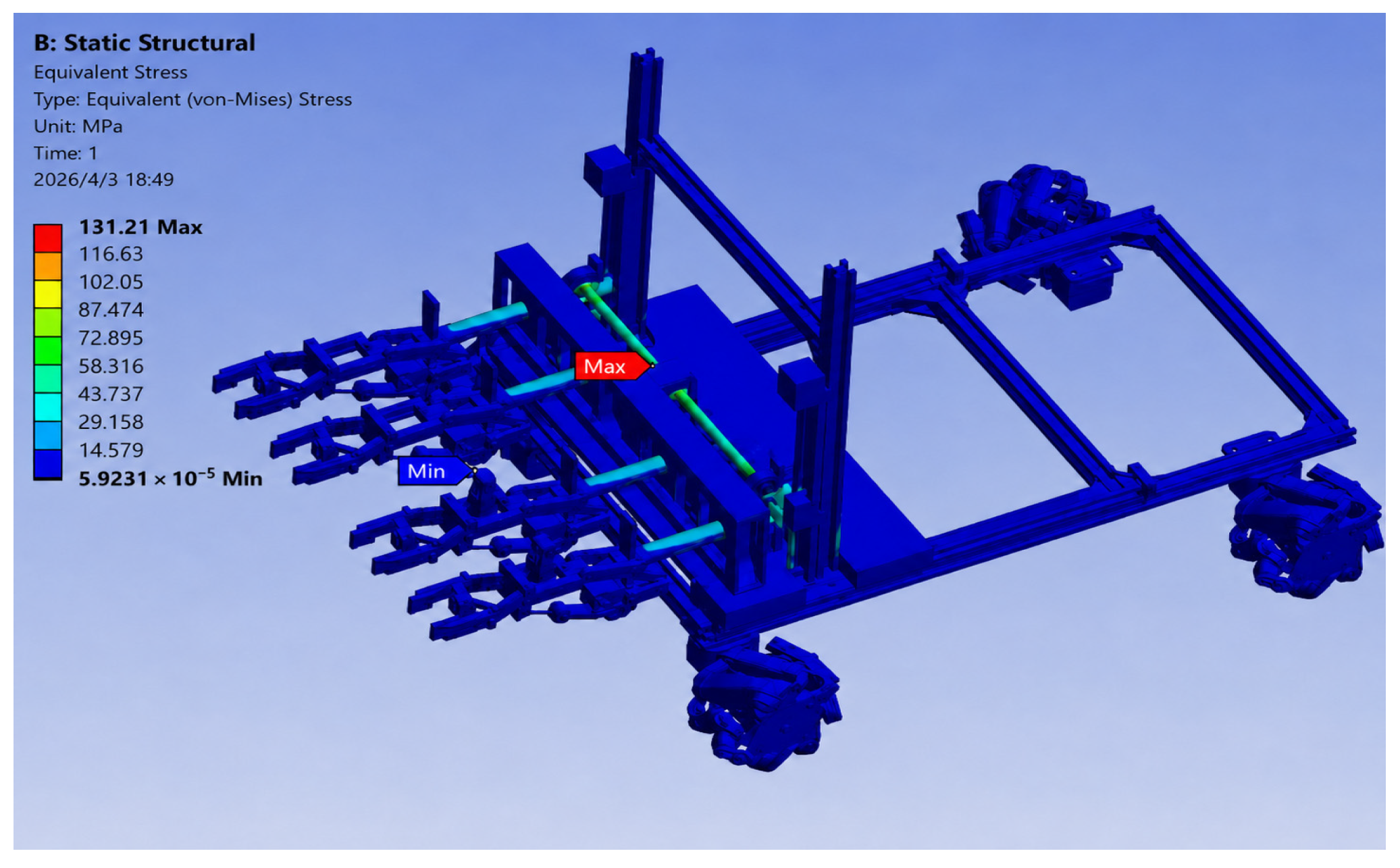
The equivalent stress contour of the whole system structure under LC1 static lifting is shown in
Figure 9. The maximum von Mises stress is retained as 131.21 MPa, and it occurs at the loaded connection between the clamping device and the frame. The remaining frame regions show lower and more uniform stress. Because the yield strength of No. 45 steel is 355 MPa, the calculated static safety factor is 2.71, indicating that the structure satisfies the baseline strength requirement.
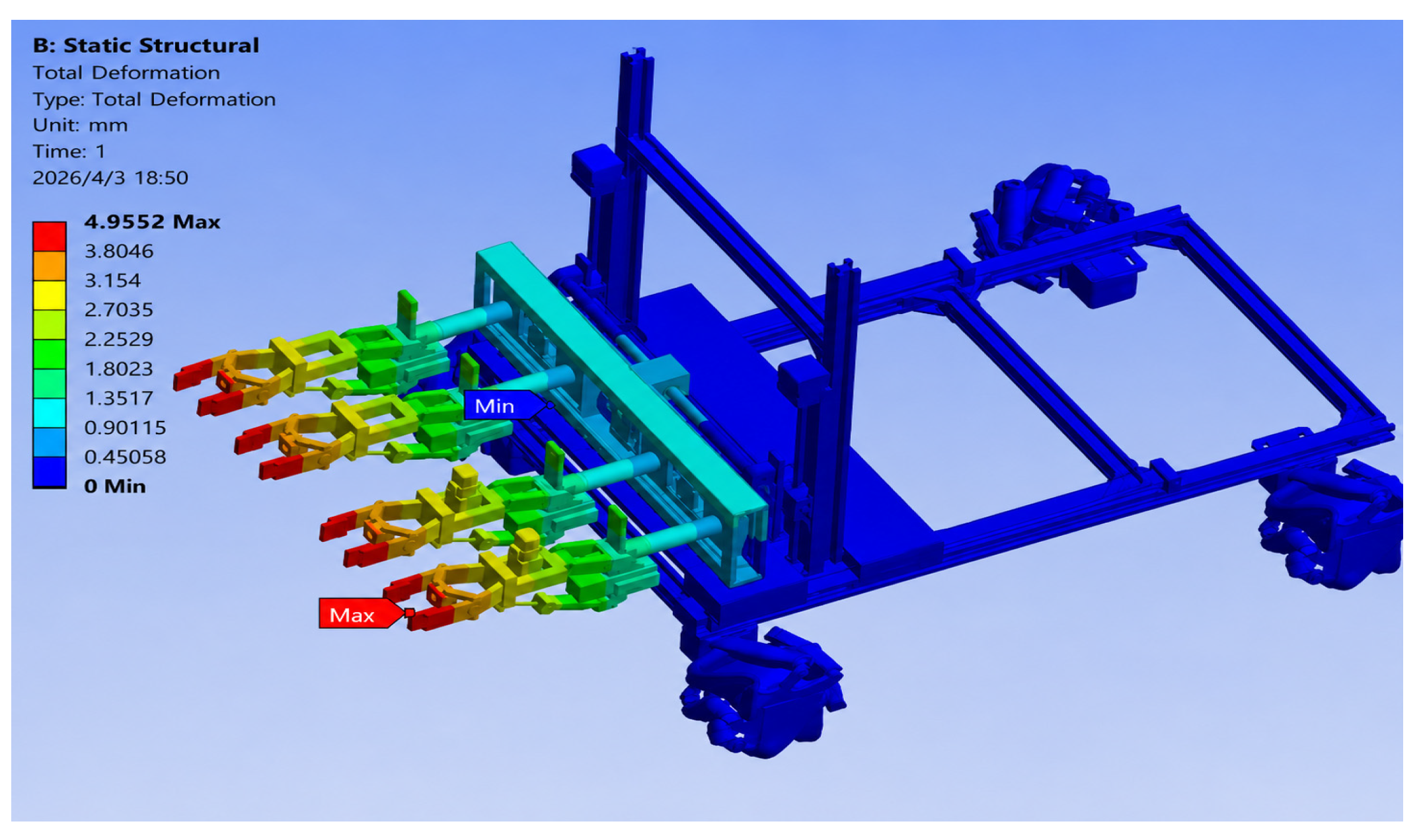
The total deformation contour of the whole system under LC1 static lifting is shown in
Figure 10. The maximum deformation is retained as 4.0552 mm and occurs near the front-end clamping actuator, while the upper frame and base show relatively small displacement. This deformation level is acceptable for prototype-level transfer positioning and is unlikely to affect the adaptive clamping process under the baseline load. The local stress concentration at the clamping-device joint should still be considered in the next structural reinforcement stage.
3.4. Preliminary Dynamic, Vibration, and Fatigue Assessment
The quasi-dynamic cases were estimated by converting acceleration and braking effects into equivalent inertial loads. LC2 corresponds to a vertical dynamic amplification of 1.5 times the bicycle weight during lifting, LC3 applies a 0.4 g longitudinal inertial component during emergency braking, and LC4 represents lateral eccentric loading caused by an off-center bicycle posture. LC5 uses a 2 Hz equivalent vertical excitation to represent low-speed transfer vibration and actuator-induced fluctuation.
Among the preliminary cases, LC3 gives the highest stress of 176.3 MPa and the largest deformation of 5.12 mm. This maximum stress remains below the 355 MPa yield strength of No. 45 steel, with a yield safety factor of approximately 2.01. Therefore, no immediate yielding risk is predicted under the selected quasi-dynamic load screening cases, although the clamping–frame connection remains the critical location for reinforcement.
For the initial vibration check, the 2 Hz equivalent vertical load did not produce a stress level higher than the emergency-braking case. A beam-stiffness estimate of the main frame indicates that the first global bending mode is expected to be much higher than the 2 Hz low-speed transfer excitation, so resonance is not expected in the prototype operating range. This conclusion should be verified by a full modal test or transient dynamic simulation before field deployment.
A simplified fatigue screening was also conducted using the mean stress from the lifting condition and an estimated alternating stress caused by repeated lifting, braking, and transfer vibration. With a conservative corrected endurance limit of approximately 160 MPa for the structural steel assembly, a Goodman-type estimate gives a preliminary fatigue safety factor of about 1.6 at the critical clamping–frame joint. This result is suitable only for early engineering screening; welded details, bolt preload, surface treatment, impact events, and long-term corrosion should be included in future full-scale fatigue tests.
Overall, the original static result of 131.21 MPa maximum stress and 4.0552 mm maximum deformation is retained, and the additional quasi-dynamic screening indicates that the prototype structure has an acceptable preliminary safety margin. Complete full-scale transient dynamics, road-vibration testing, and long-duration fatigue validation remain future work.
4. Experimental Testing and Analysis of the Collection and Transfer System Prototype
To complement the static finite-element analysis, prototype experiments were conducted to evaluate the adaptive spacing accuracy, multi-posture grasping reliability, transfer positioning accuracy, vibration stability, motor load response, and scale-model limitations of the proposed collection–transfer mechanism. All tests were performed under controlled 1:7 scale-model laboratory conditions. Therefore, the experiments were used for prototype-level feasibility and statistical repeatability assessment rather than as full-scale engineering validation.
4.1. Experimental Platform and Scale-Model Design
The experimental platform was constructed according to a 1:7 geometric scale ratio and consisted of scaled bicycle models, an adaptive gripping mechanism, a transfer base, a conveyor chain group, a photoelectric positioning array, and a data-acquisition system. The scaled wheel diameters were 73 mm, 80 mm, 86 mm, and 94 mm, corresponding to common shared-bicycle wheel sizes after geometric reduction. The adjustable-angle base provided tilt angles from 0° to 45° for fallen or leaning bicycle conditions, and the rectangular transfer base was 600 mm long and 400 mm wide. Force sensing, motor-current acquisition, photoelectric positioning, and optical displacement measurement were used to record the collection and transfer process; the vibration and displacement signals were sampled at 100 Hz.
The 1:7 scale model was used to verify the feasibility and relative performance trends of the collection–transfer mechanism, including adaptive gripping, positioning repeatability, and transfer stability. It was not intended to fully reproduce the dynamic similarity of a full-scale system, because mass, inertia, contact force, tire-ground friction, and vibration response do not scale linearly with geometric size.
4.2. Test Protocol, Evaluation Metrics, and Data Processing
Four groups of experiments were carried out. First, in the adaptive spacing test, each wheel-diameter group was tested 10 times. The target gripper spacing was set according to the corresponding scaled wheel diameter, and the measured spacing was recorded after the rack-and-pinion mechanism stopped. A trial was regarded as valid when the absolute spacing error was within ±1.5 mm and the adjustment cycle was completed within 3 s.
Second, in the multi-posture grasping test, upright, side-fallen, and obstacle-leaning postures were evaluated at 0°, 30°, and 45°, respectively. The gripper closing speed and lifting speed were kept constant at 15 mm/s and 20 mm/s in the scale-model test. The minimum acceptable clamping force was set to 7.5 N. A successful grasp required the wheel to be clamped, lifted, and lowered without visible slip, detachment, or interference with the transfer fixture.
Third, in the transfer stability test, a 94 mm wheel-diameter model was lowered until the photoelectric array detected the tire position. The conveyor chain then transported the model horizontally at 0.1 m/s. Vertical sinusoidal excitation with an amplitude of ±5 mm, a frequency of 2 Hz, and a duration of 10 s was applied to the transfer base. Positioning error, maximum vibration displacement, motor current, clamping-force fluctuation, and pose displacement were recorded.
Fourth, in the dynamic grasping stability test, tilt-angle groups of 0°, 15°, 30°, 45°, and 60° were evaluated to quantify the degradation of grasping performance as posture deviation increased. Each tilt-angle group was treated as a binomial success-rate test, and the positioning error, gripper response time, and maximum vibration displacement were summarized for comparison.
The main indicators are calculated as follows: spacing error es = |dm−dt|, where dm is the measured spacing and dt is the target spacing; success rate Ps = Ns/N × 100%, where Ns is the number of successful trials and N is the total number of trials; coefficient of variation CV = s/mean × 100%; and the 95% confidence interval for a mean value was calculated as CI95% = xbar ± t0.975, n − 1 × s/sqrt (n). For success rates, Wilson binomial confidence intervals were used because the outcomes were pass/fail trials.
4.3. Experimental Results and Statistical Analysis
The adaptive spacing results are summarized in
Table 8. The first numerical column in the original statistics represented spacing error rather than spacing time; therefore, the column heading was corrected to mean spacing error. For the 73–94 mm wheel groups, the mean spacing error increased from 0.42 mm to 0.68 mm, and all 95% confidence intervals remained below the ±1.5 mm tolerance. The mean adjustment time increased from 2.25 s to 2.56 s but remained below the 3 s design threshold. The gradual increase is mechanically consistent with the larger travel distance and friction accumulation in the rack-and-pinion transmission.
The multi-posture grasping results are shown in
Table 9. The success rates were corrected to integer success counts so that each percentage corresponds to a physically possible number of trials. The upright posture achieved 98.0% success, while the side-fallen and obstacle-leaning postures achieved 96.0% and 95.0%, respectively. The clamping-force CV increased from 2.5% to 4.7% as tilt angle increased, indicating that posture compensation increased force fluctuation. Nevertheless, the mean clamping force remained within the scaled acceptance range, and the Wilson confidence intervals stayed above the preliminary 90% reliability threshold.
The transfer stability results are given in
Table 10. Across five transfer groups, the average group mean of the photoelectric positioning error was 1.38 mm, and the maximum positioning error was 1.98 mm. The maximum vibration displacement did not exceed 1.96 mm under the 2 Hz excitation, while the motor current remained around 2.45 ± 0.15 A. The motor-current CV was 6.1%, indicating that the transfer load did not produce a sudden current increase under the laboratory test condition. The clamping-force fluctuation standard deviation was 0.16–0.19 N, which suggests that the self-locking gripper limited vibration transmission during transfer.
Table 11 summarizes the dynamic grasping results for different tilt angles. When the bicycle tilt angle was 30° or lower, the success rate remained at or above 94.0%, the mean positioning error was no more than 2.5 mm, and the maximum vibration displacement was no more than 2.3 mm. At 45° and 60°, the success rate decreased to 90.0% and 83.0%, while the positioning error and response time increased. This result indicates that large posture deviation increases the vision-guided approach error and the required gripper compensation, so the current mechanism is more reliable for upright, side-fallen, and moderate-leaning bicycles than for severe tilting conditions.
4.4. Scalability, Comparative Discussion, and Limitations
The scale-model tests validated the basic mechanical sequence of adaptive spacing, wheel clamping, photoelectric positioning, transfer, and vibration resistance under controlled laboratory conditions. However, scalability remains a key limitation. Full-scale dynamic loads will be affected by mass and inertia scaling, contact stiffness, tire–ground friction, impact during lifting, and vibration transmitted through the mobile chassis. These effects cannot be fully inferred from a 1:7 geometric model. Therefore, dynamic finite-element analysis, fatigue analysis, full-scale vibration tests, and outdoor field trials are required before engineering deployment.
A qualitative comparison with common collection and transfer approaches is provided in
Table 12. The proposed system integrates bicycle identification, adaptive grasping, transfer fixation, cleaning, and preliminary inspection in one robotic platform. The comparison is qualitative because the available experiments do not provide directly comparable full-scale operating time, cost, or failure-rate data for all alternative approaches.
Operational autonomy is also not fully validated in this study. The current experiments focus on mechanism-level collection and transfer rather than complete operation in dense urban environments. Localization, route planning, obstacle avoidance, interaction with pedestrians and vehicles, multi-robot coordination, dispatch scheduling, and decision-making under dynamic demand must be further developed and tested. The visual recognition module reported in
Section 2.7 provides preliminary perception support, but hardware requirements, image-processing latency, control decision time, actuator response time, and end-to-end cycle time should be measured with the final embedded computing platform. The cleaning and damage-inspection modules should also be regarded as prototype-level functional integrations until their detection accuracy and maintenance effect are validated independently.
5. Conclusions
This study proposes an integrated robotic system for shared bicycle collection, transfer, fixation, cleaning, and preliminary inspection. A laboratory-scale prototype was developed to evaluate the feasibility of the adaptive spacing mechanism, multi-posture gripping process, photoelectric positioning, and transfer-stability sequence. The results provide prototype-level evidence for the proposed collection–transfer concept, while full urban autonomous operation remains outside the direct validation scope of this study.
Static finite-element analysis of the collection and transfer structure showed that the maximum von Mises stress was 131.21 MPa under the simulated loading condition, which is lower than the 355 MPa yield strength of 45 steel. The maximum deformation was 4.0552 mm and occurred near the end of the clamping actuator. These results indicate that the static strength and stiffness satisfy the preliminary design requirements under the specified simulation assumptions, but they do not verify fatigue strength, impact behavior, or vibration response during mobile operation.
Under controlled 1:7 scale-model laboratory conditions, the adaptive spacing error ranged from 0.42 ± 0.18 mm to 0.68 ± 0.24 mm, and the adjustment time ranged from 2.25 ± 0.28 s to 2.56 ± 0.33 s. Multi-posture grasping success rates were 95.0–98.0%, and the clamping-force CV remained below 5%. In the transfer test, the average photoelectric positioning error was about 1.38 mm, the maximum vibration displacement was 1.96 mm, and the motor current remained around 2.45 ± 0.15 A. In the dynamic grasping test, the success rate decreased from 98.0% at 0° to 83.0% at 60°, indicating that large tilt angles significantly increase positioning error, response time, and vibration displacement.
The main limitations are that the current validation is based on a 1:7 scale prototype and does not fully verify full-scale dynamic loads, fatigue strength, vibration during mobile operation, long-term reliability, outdoor adaptability, or operation in different regional deployment conditions. Autonomous navigation, path planning, obstacle avoidance, multi-robot coordination, and real-time computational performance also require further verification. Future work will include full-scale prototype testing, dynamic finite-element analysis, fatigue and vibration tests, outdoor road tests, embedded-system timing tests, and multi-region deployment assessment.
Author Contributions
Conceptualization, J.W. and S.L.; methodology and software, J.W.; validation, J.W., S.L., X.J., Y.Y., B.S., N.Z. and D.Z.; formal analysis, X.J. and B.S.; investigation, S.L. and J.W.; resources, J.W. and D.Z.; data curation, Y.Y. and N.Z.; writing—original draft preparation, Y.Y. and N.Z.; writing—review and editing, X.J. and J.W.; visualization, J.W.; supervision, D.Z.; project administration, J.W. and D.Z.; funding acquisition, J.W. and D.Z. All authors have read and agreed to the published version of the manuscript.
Funding
This work was supported by the Natural Science Foundation of Ningxia (No. 2023AAC03309); National College Student Innovation and Entrepreneurship Training Program (No. 202511407012).
Institutional Review Board Statement
Not applicable.
Informed Consent Statement
Not applicable.
Data Availability Statement
All data generated or analyzed during this study are included in this published article.
Conflicts of Interest
The authors declare no conflicts of interest.
References
- Caggiani, L.; Ottomanelli, M. A Modular Soft Computing based Method for Vehicles Repositioning in Bike-sharing Systems. Procedia-Soc. Behav. Sci. 2012, 54, 675–684. [Google Scholar] [CrossRef]
- Shui, C.; Szeto, W. Dynamic green bike repositioning problem—A hybrid rolling horizon artificial bee colony algorithm approach. Transp. Res. Part D Transp. Environ. 2018, 60, 119–136. [Google Scholar] [CrossRef]
- Chechkin, A.; Pleshakova, E.; Gataullin, S. Hybrid Neural Network Transformer for Detecting and Classifying Destructive Content in Digital Spaces. Algorithms 2025, 18, 735. [Google Scholar] [CrossRef]
- Zhu, Y.; Ma, Z.; Wang, S.; Wen, Z. Optimization Scheduling Problem of Shared Bicycles Based on BP Neural Network. Netw. Secur. Technol. Appl. 2018, 11, 44–45. [Google Scholar] [CrossRef]
- Zhao, B.; Xie, R. Zoning Dynamic Scheduling Optimization of Shared Bicycles. Hubei Univ. Technol. 2023, 38, 116–120. [Google Scholar] [CrossRef]
- Shen, R.; He, W.; Xu, Y. Crowdsourcing Scheduling System of Campus Shared Bicycles Based on Dynamic Perception of Spatiotemporal Distribution. J. Data Acquis. Process. 2025, 40, 972–985. [Google Scholar]
- Tal, R.; Michal, T.; Forma, I.A. Static repositioning in a bike-sharing system: Models and solution approaches. EURO J. Transp. Logist. 2013, 2, 187–229. [Google Scholar] [CrossRef]
- Liu, S. Research on Motion Control of Manipulator Based on Visual Perception. Master’s Thesis, Lanzhou University of Technology, Lanzhou, China, 2018. [Google Scholar]
- Kang, H.; Han, D.; Son, K.; Kang, M.-S. Design of a reconfigurable three-finger gripper for versatile grasping tasks. Robot. Auton. Syst. 2026, 196, 105264. [Google Scholar] [CrossRef]
- Cai, F.; Guo, Q. Research on Robot Sorting Based on Dynamic Grasping Algorithm. Autom. Instrum. 2018, 10–13. [Google Scholar] [CrossRef]
- Lei, X.Y.; Yang, J.Q. Dispatching strategy of shared bicycles for morning peak tidal travel based on spatial distribution. Sustain. Futures 2025, 10, 101090. [Google Scholar] [CrossRef]
- Wang, X.; Zheng, S.; Wang, L.; Han, S.; Liu, L. Multi-objective optimal scheduling model for shared bikes based on spatiotemporal big data. J. Clean. Prod. 2023, 421, 138362. [Google Scholar] [CrossRef]
- Chen, J.G.; Li, K.L.; Li, K.Q.; Yu, P.S.; Zeng, Z. Dynamic Bicycle Dispatching of Dockless Public Bicycle-sharing Systems Using Multi-objective Reinforcement Learning. ACM Trans. Cyber-Phys. Syst. 2021, 5, 3447623. [Google Scholar]
- Qiu, Y.T.; Ji, W.X.; Zhang, C.Y. Multi-objective Job Shop Scheduling Combined with Hybrid Evolutionary Algorithm and Knowledge. China Mech. Eng. 2020, 31, 2979–2987. [Google Scholar] [CrossRef]
Figure 1.
Overall structure of the collection robot, including the Mecanum-wheel base, adaptive gripping mechanism, and transverse adjustment modules for multi-posture shared-bicycle pickup. 1. Mecanum wheel. 2. Gripping mechanism. 3. Adaptive device. 4. Omni-directional traversal mechanism. 5. Vertical and horizontal shifting device.
Figure 1.
Overall structure of the collection robot, including the Mecanum-wheel base, adaptive gripping mechanism, and transverse adjustment modules for multi-posture shared-bicycle pickup. 1. Mecanum wheel. 2. Gripping mechanism. 3. Adaptive device. 4. Omni-directional traversal mechanism. 5. Vertical and horizontal shifting device.
Figure 2.
Transfer robot architecture with fixing-storage, cleaning, infrared inspection, water tank, and Mecanum-wheel mobility modules. 1. Mecanum wheel. 2. Fixing and storage device. 3. Water tank. 4. Rotary gate valve. 5. Cleaning and inspection device.
Figure 2.
Transfer robot architecture with fixing-storage, cleaning, infrared inspection, water tank, and Mecanum-wheel mobility modules. 1. Mecanum wheel. 2. Fixing and storage device. 3. Water tank. 4. Rotary gate valve. 5. Cleaning and inspection device.
Figure 3.
Motor-driven gripping device with telescopic rod, rack slider, and pneumatic rack-slider mechanism for wheel/frame clamping and posture adjustment. 1. Gripper. 2. Gripper opening/closing motor. 3. Telescopic rod. 4. Adaptive-device connecting rod. 5. Rack slider. 6. Pneumatic rack-slider mechanism.
Figure 3.
Motor-driven gripping device with telescopic rod, rack slider, and pneumatic rack-slider mechanism for wheel/frame clamping and posture adjustment. 1. Gripper. 2. Gripper opening/closing motor. 3. Telescopic rod. 4. Adaptive-device connecting rod. 5. Rack slider. 6. Pneumatic rack-slider mechanism.
Figure 4.
Adaptive wheel-spacing device: (a) initial spacing state and (b) adjusted rack-slider state driven by the gear mechanism. 1. Outer frame. 2. Gear. 3. Rack slider. 4. Gripper fixing device. 5. Pinion drive motor. 6. Gear drive motor.
Figure 4.
Adaptive wheel-spacing device: (a) initial spacing state and (b) adjusted rack-slider state driven by the gear mechanism. 1. Outer frame. 2. Gear. 3. Rack slider. 4. Gripper fixing device. 5. Pinion drive motor. 6. Gear drive motor.
Figure 5.
Omnidirectional transverse mechanism combining front–back, left–right, and up–down translation units for gripper positioning. 1. Front–back translation device. 2. Left–right translation device. 3. Up–down translation device.
Figure 5.
Omnidirectional transverse mechanism combining front–back, left–right, and up–down translation units for gripper positioning. 1. Front–back translation device. 2. Left–right translation device. 3. Up–down translation device.
Figure 6.
Mecanum-wheel mobile base used by both collection and transfer robots to support low-speed omnidirectional positioning. 1. Mecanum wheel. 2. Mobile base. 3. Drive motor.
Figure 6.
Mecanum-wheel mobile base used by both collection and transfer robots to support low-speed omnidirectional positioning. 1. Mecanum wheel. 2. Mobile base. 3. Drive motor.
Figure 7.
Fixed storage device with a motor-driven gripper and slider base for receiving and securing collected bicycles on the transfer robot. 1. Drive motor. 2. Gripper. 3. Slider base.
Figure 7.
Fixed storage device with a motor-driven gripper and slider base for receiving and securing collected bicycles on the transfer robot. 1. Drive motor. 2. Gripper. 3. Slider base.
Figure 8.
Cleaning and inspection device with four water-jet nozzles and infrared sensors for preliminary washing and fault screening. 1. Water tank. 2. Nozzle. 3. Infrared detection device.
Figure 8.
Cleaning and inspection device with four water-jet nozzles and infrared sensors for preliminary washing and fault screening. 1. Water tank. 2. Nozzle. 3. Infrared detection device.
Figure 9.
Von Mises stress contour for LC1 static lifting of a 20 kg bicycle; the maximum stress of 131.21 MPa occurs at the clamping–frame connection and remains below the 355 MPa yield strength.
Figure 9.
Von Mises stress contour for LC1 static lifting of a 20 kg bicycle; the maximum stress of 131.21 MPa occurs at the clamping–frame connection and remains below the 355 MPa yield strength.
Figure 10.
Total deformation contour for LC1 static lifting; the maximum displacement of 4.0552 mm appears near the front-end clamping actuator and indicates acceptable prototype-level stiffness for transfer positioning.
Figure 10.
Total deformation contour for LC1 static lifting; the maximum displacement of 4.0552 mm appears near the front-end clamping actuator and indicates acceptable prototype-level stiffness for transfer positioning.
Table 1.
Qualitative comparison between common bicycle redistribution approaches and the proposed integrated collection–transfer system.
Table 1.
Qualitative comparison between common bicycle redistribution approaches and the proposed integrated collection–transfer system.
| Approach | Bicycle Recognition Method | Grasping and Transfer Capability | Cleaning/Inspection Capability | Automation Degree | Main Limitation | Contribution Boundary in This Paper |
|---|
| Manual collection | Human visual judgment | Flexible but labor-intensive loading | Manual inspection only | Low | High labor cost and unstable response time | Reference baseline for workflow demand |
| Conventional dispatch vehicle | Operator search or platform order | Batch transport after manual loading | Usually unavailable | Low to medium | Cannot solve irregular parking without workers | Shows why a collection mechanism is required |
| Generic mobile manipulator | General object detection or teleoperation | Limited by arm payload and bicycle posture variation | Usually separate module | Medium | Difficult wheel adaptation and low storage density | Comparison object for integrated mechanism design |
| Proposed system | Camera-based bicycle, wheel, and posture detection | Adaptive wheel clamp, lifting, 90° correction, and transfer fixing | Integrated water–jet cleaning and infrared preliminary inspection | Prototype-level autonomy | Outdoor full-scale driving and long-term reliability still require field validation | Integrated mechanical collection–transfer–cleaning system for multi-posture shared bicycles |
Table 2.
Main technical specifications of the prototype collection robot.
Table 2.
Main technical specifications of the prototype collection robot.
| Technical Parameters of the Robot | Technical Specifications |
|---|
| Degrees of Freedom | 6 |
| Supply Voltage (V) | 50 |
| Payload Capacity (kg) | 10 |
| Gripper Rotation Angle (°) | 90 |
| Longitudinal Travel Distance (cm) | 90 |
| Lateral Travel Distance (cm) | 20 |
| Maximum Lateral Travel Speed (r/min) | 200 |
Table 3.
Basic parameters of the self-built multi-posture shared-bicycle dataset.
Table 3.
Basic parameters of the self-built multi-posture shared-bicycle dataset.
| Item | Setting or Description |
|---|
| Total images | 6200 images, including on-site photographs, laboratory scale-model images, and extracted video frames. |
| Data split | Training/validation/test = 70%/20%/10%, corresponding to 4340/1240/620 images. |
| Typical scenes | Upright, side-fallen, inclined, partially occluded, mixed-brand, overlapping, and low-light parking conditions. |
| Annotated objects | Bicycle body, front wheel, rear wheel, handlebar, saddle, and damaged or abnormal component. |
| Annotation format | Manual bounding-box annotation converted to YOLO format after label consistency checking. |
| Use in this paper | Provides reproducible perception input for localization, posture recognition, and gripper-spacing selection; it is not presented as a new public benchmark. |
Table 4.
YOLOv8 model training and deployment hyperparameters.
Table 4.
YOLOv8 model training and deployment hyperparameters.
| Parameter | Value Used for the Engineering Prototype |
|---|
| Detector | YOLOv8s, selected as the accuracy-speed balance model for the collection robot. |
| Input size | 640 × 640 pixels. |
| Batch size and epochs | Batch size 16; 150 epochs; early stopping patience of 25 epochs. |
| Optimizer and learning rate | AdamW optimizer; initial learning rate 0.001; cosine learning-rate decay. |
| Data augmentation | Random scaling, HSV perturbation, horizontal flipping, Mosaic in the early stage, and random local occlusion. |
| Training hardware | RTX 3060-class GPU workstation. |
| Deployment hardware | Edge computer comparable to Jetson Orin NX or compact x86 CUDA industrial computer. |
| Output to controller | Bicycle center, wheel centers, posture category, and abnormal-part flag. |
Table 5.
Compact engineering comparison of detection accuracy and inference speed.
Table 5.
Compact engineering comparison of detection accuracy and inference speed.
| Model | Precision (%) | Recall (%) | mAP@0.5 (%) | mAP@0.5:0.95 (%) | FPS | Latency (ms) | Engineering Note |
|---|
| YOLOv8n | 94.1 | 92.8 | 95.4 | 78.6 | 42.7 | 23.4 | Fastest option but lower small-part robustness. |
| YOLOv8s | 96.3 | 94.7 | 97.1 | 82.3 | 31.2 | 32.1 | Selected balance for real-time collection control. |
| SSD-MobileNetV2 | 91.6 | 89.5 | 92.8 | 72.4 | 25.8 | 38.8 | Lower robustness under occlusion and mixed parking. |
| Faster R-CNN | 97.0 | 95.2 | 97.8 | 84.1 | 7.4 | 135.0 | Accurate but too slow for the prototype control cycle. |
Table 6.
Finite-element model settings and load definitions.
Table 6.
Finite-element model settings and load definitions.
| Item | Setting Used in the Prototype-Level Finite-Element Model |
|---|
| Material model | Linear elastic isotropic No. 45 steel; E = 206 GPa, ν = 0.30, ρ = 7850 kg/m3, yield strength σ_y = 355 MPa. |
| Element and mesh | Ten-node tetrahedral solid elements; 4 mm global mesh size and 2 mm local refinement at gripper-frame joints and rack-slider transitions. |
| Model size | Approximately 218,000 nodes and 126,000 elements after local refinement. |
| Contact definition | Bonded contact for welded/bolted structural joints; frictional contact with μ = 0.30 at rubber gripper-pad contact; sliding guides simplified as bonded supports for strength screening. |
| Constraints | Full fixed constraint applied to the bottom supporting surfaces and base mounting pads; no symmetry constraint was used because the bicycle load can be eccentric. |
| Load application | Gravity, 20 kg bicycle weight, clamping reaction, vertical acceleration, longitudinal braking inertia, lateral eccentric load, and equivalent 2 Hz vertical vibration were applied to corresponding load-bearing surfaces. |
| Mesh convergence | Refining the local mesh from 3 mm to 2 mm changed maximum von Mises stress by less than 4.8% and maximum displacement by less than 2.5%. |
Table 7.
Preliminary finite-element results under static and quasi-dynamic load cases.
Table 7.
Preliminary finite-element results under static and quasi-dynamic load cases.
| Load Case | Equivalent Operating Condition | Maximum von Mises Stress (MPa) | Maximum Deformation (mm) | Yield Safety Factor |
|---|
| LC1 | Static lifting of a 20 kg bicycle | 131.21 | 4.0552 | 2.71 |
| LC2 | 0.5 g vertical lifting acceleration | 165.8 | 4.84 | 2.14 |
| LC3 | 0.4 g emergency braking during transfer | 176.3 | 5.12 | 2.01 |
| LC4 | Lateral eccentric bicycle load | 152.6 | 4.47 | 2.33 |
| LC5 | Equivalent 2 Hz vertical vibration load | 158.9 | 4.61 | 2.23 |
Table 8.
Adaptive spacing accuracy and adjustment time for four scaled wheel-diameter groups (n = 10 per group).
Table 8.
Adaptive spacing accuracy and adjustment time for four scaled wheel-diameter groups (n = 10 per group).
| Wheel Diameter (mm) | n | Mean Spacing Error (mm) | 95% CI of Error (mm) | Mean Adjustment Time (s) | 95% CI of Time (s) |
|---|
| 73 | 10 | 0.42 ± 0.18 | 0.29–0.55 | 2.25 ± 0.28 | 2.05–2.45 |
| 80 | 10 | 0.51 ± 0.22 | 0.35–0.67 | 2.38 ± 0.31 | 2.16–2.60 |
| 86 | 10 | 0.59 ± 0.19 | 0.45–0.73 | 2.47 ± 0.29 | 2.26–2.68 |
| 94 | 10 | 0.68 ± 0.24 | 0.51–0.85 | 2.56 ± 0.33 | 2.32–2.80 |
Table 9.
Multi-posture grasping reliability with Wilson 95% confidence intervals for success rate (n = 100 per posture).
Table 9.
Multi-posture grasping reliability with Wilson 95% confidence intervals for success rate (n = 100 per posture).
| Posture Type | Tilt Angle (°) | Successes/N | Success Rate (%) | Wilson 95% CI (%) | Force Range (N) | Mean Clamping Force (N) | CV (%) |
|---|
| Upright | 0 | 98/100 | 98.0 | 93.0–99.4 | 7.6–8.4 | 8.0 ± 0.2 | 2.5 |
| Side-fallen | 30 | 96/100 | 96.0 | 90.2–98.4 | 7.8–8.7 | 8.3 ± 0.3 | 3.6 |
| Obstacle-leaning | 45 | 95/100 | 95.0 | 88.8–97.8 | 8.1–9.0 | 8.5 ± 0.4 | 4.7 |
Table 10.
Transfer positioning, vibration, motor-current, and clamping-force stability under 2 Hz vertical excitation.
Table 10.
Transfer positioning, vibration, motor-current, and clamping-force stability under 2 Hz vertical excitation.
| Group | Positioning Error (mm), Mean ± SD | Max. Positioning Error (mm) | Max. Vibration Displacement (mm) | Motor Current (A), Mean ± SD | Force Range (N) | SD of Clamping Force (N) | Max. Pose Displacement (mm) |
|---|
| 1 | 1.38 ± 0.51 | 1.96 | 1.74 | 2.44 ± 0.15 | 11.7–12.2 | 0.17 | 1.72 |
| 2 | 1.42 ± 0.49 | 1.91 | 1.82 | 2.47 ± 0.14 | 11.8–12.3 | 0.18 | 1.80 |
| 3 | 1.35 ± 0.53 | 1.98 | 1.96 | 2.45 ± 0.16 | 11.7–12.3 | 0.19 | 1.68 |
| 4 | 1.40 ± 0.47 | 1.89 | 1.77 | 2.43 ± 0.13 | 11.9–12.3 | 0.16 | 1.75 |
| 5 | 1.33 ± 0.50 | 1.94 | 1.71 | 2.46 ± 0.15 | 11.8–12.2 | 0.18 | 1.70 |
Table 11.
Dynamic grasping stability by tilt angle (n = 100; Wilson 95% CI for success rate).
Table 11.
Dynamic grasping stability by tilt angle (n = 100; Wilson 95% CI for success rate).
| Tilt Angle (°) | Successes/N | Success Rate (%) | Wilson 95% CI (%) | Mean Pos. Error (mm) | Response Time (s) | Max. Vib. Displacement (mm) |
|---|
| 0 | 98/100 | 98.0 | 93.0–99.4 | 1.2 | 0.35 | 0.8 |
| 15 | 96/100 | 96.0 | 90.2–98.4 | 1.8 | 0.42 | 1.5 |
| 30 | 94/100 | 94.0 | 87.5–97.2 | 2.5 | 0.51 | 2.3 |
| 45 | 90/100 | 90.0 | 82.6–94.5 | 3.7 | 0.68 | 3.9 |
| 60 | 83/100 | 83.0 | 74.5–89.1 | 5.2 | 0.95 | 5.6 |
Table 12.
Qualitative comparison between the proposed system and existing bicycle collection and transfer approaches.
Table 12.
Qualitative comparison between the proposed system and existing bicycle collection and transfer approaches.
| Approach | Bicycle Identification | Grasping and Transfer Capability | Cleaning/Inspection Function | Automation Level | Main Limitation |
|---|
| Manual collection | Human visual judgment | Flexible but labor-intensive | Manual inspection only | Low | High labor cost and low repeatability |
| Conventional dispatch vehicle | Manual or dispatch-list-based | Bulk loading and unloading | Usually separated from collection | Low to medium | Limited response to scattered and fallen bicycles |
| Generic mobile manipulator | Camera or LiDAR perception may be added | General grasping, not optimized for bicycle wheels | Usually not integrated | Medium | Requires task-specific gripper and transfer fixture |
| Proposed collection–transfer system | YOLOv8-based bicycle recognition and photoelectric positioning | Adaptive wheel spacing, multi-posture grasping, and conveyor transfer | Prototype-level cleaning and infrared inspection integrated | Medium to high under laboratory conditions | Full-scale dynamics and outdoor autonomy require further validation |
| Disclaimer/Publisher’s Note: The statements, opinions and data contained in all publications are solely those of the individual author(s) and contributor(s) and not of MDPI and/or the editor(s). MDPI and/or the editor(s) disclaim responsibility for any injury to people or property resulting from any ideas, methods, instructions or products referred to in the content. |