Article

Vortex Airflow Coupled with Flexible Collision: An Optimized Low-Damage Threshing Approach for High-Moisture Maize

College of Agricultural Equipment Engineering, Henan University of Science and Technology, Luoyang 471000, China
*
Author to whom correspondence should be addressed.
Appl. Sci. 2026, 16(13), 6542; https://doi.org/10.3390/app16136542
Submission received: 1 June 2026 / Revised: 25 June 2026 / Accepted: 25 June 2026 / Published: 1 July 2026
(This article belongs to the Section Agricultural Science and Technology)

Abstract

To solve the problems of high kernel breakage and low threshing efficiency in the threshing operation of high-moisture maize, this study designs an adaptive threshing device based on the coupled working principle of vortex airflow driving and flexible collision. The adaptive threshing mode enables maize ears to move spirally upward under vortex airflow and make compliant contact with flexible components. By adopting repeated mild collisions instead of the rigid violent impact used in traditional devices, low-damage maize threshing is achieved. Preliminary experiments verify that the layout density of flexible threshing units, tangential airflow velocity, and feeding speed are the key factors affecting threshing performance. A regression orthogonal rotational combination test is conducted to systematically explore the single-factor and interactive effects on threshing efficiency, and the optimal parameter configuration is obtained. The test results show that, under the conditions of circumferential angular spacing of 21.5°, tangential velocity of 45.9 m/s and feed rate of 0.65 kg/s, the maize threshing rate reaches 96.1% while the grain breakage rate is controlled below 0.1%, which is significantly superior to conventional rigid threshing methods. This research provides a new technical scheme and experimental data reference for the low-damage threshing study of high-moisture maize.

1. Introduction

Maize is one of the most important crops in the world and also a source of high-quality feed, as well as pharmaceutical and chemical raw materials [1,2,3]. At present, mechanical grain harvesting represents the development direction of maize harvesting technology in China and is crucial for realizing whole-process mechanization and transforming production modes of maize. Maize harvested in the Huang-Huai-Hai region of China generally has a high moisture content, resulting in a high breakage rate of maize grains during mechanical harvesting. At high moisture levels, the maize endosperm maintains high toughness, whereas the seed coat becomes swollen and fragile. The intense rigid impact generated by traditional threshing machines can easily cause surface cracking and internal fracture of moist kernels [4]. A high grain breakage rate may trigger potential problems during storage [5]. In current research on low-damage threshing of maize grains, studies mainly focus on the improvement of threshing elements. Although some representative achievements have been obtained, they still cannot overcome the limitation of threshing methods dominated by collisions with rigid elements.
To date, many researchers have carried out extensive experimental studies on maize threshing theory and technical improvement. Most early research focused on optimizing the structural dimensions and operating parameters of traditional rigid axial-flow threshing drums to balance threshing efficiency and grain loss. Pachanawan et al. [6] developed an axial-flow drum for maize threshing devices. The drum type and concave clearance have significant effects on threshing efficiency and total loss, while their influence on grain breakage is insignificant. Astanakulov et al. [7] achieved husking of maize ears with a low grain breakage rate. Li Mingrui et al. [8] designed a high-feed-rate double-longitudinal-axial-flow maize threshing device. Its optimal operating parameters are as follows: feed rate of 16 kg/s; drum speed of 400 r/min; and deflector angle of 26°. Under these conditions, the grain breakage rate is 5.02% and the unthreshed rate is 0.171%. Fan Chenlong et al. [9] designed a longitudinal-axial-flow threshing device. It was determined that the threshing performance is optimal when the feed rate is 10 kg/s, the spiral blade angle is 30°, the propeller angle is 45°, and the drum speed is 350 r/min. Dong Yue et al. [10] determined the distribution law of threshed mixture in a double longitudinal axial-flow threshing device via single-factor experiments. The optimal operating conditions are: drum speed of 400 r/min; concave clearance of 50 mm; and feed rate of 16 kg/s. Xing et al. [11] proposed a longitudinal-flow maize ear threshing device and its measurement control system. The optimal operating parameters of the threshing equipment are as follows: threshing cylinder speed of 392.40 r/min; threshing clearance of 40.70 mm; and guide vane angle of 33.16°. Li Xiaoyu et al. [12] conducted experiments on their designed threshing device. The results showed that the influence order on the grain breakage rate and unthreshed rate is drum rotational speed > concave clearance > feed rate. Abdeen et al. [13] found that the drum thresher increased the threshing throughput from 2304 kg/h to 2448 kg/h, and improved the efficiency from 98.6% to 99.07% at a rotational speed of 1500 r/min and a feed rate of 1.8 kg/s.
To reduce grain breakage during high-moisture maize threshing, scholars turned to flexible buffer structures and material mechanical property tests. Lin Niu et al. [14] designed a flexible threshing device with threshing file bars and variable stiffness springs as buffer carriers. When the spring compression stiffness is 20.83 N/mm, the rotor speed is 375 r/min, the concave clearance is 45 mm, and the grain breakage rate of maize ears is 4.7%. Shahbazi et al. [15] found that the interaction between impact energy and moisture content has a significant effect on the percentage of physical damage to maize grains. Zhu Xiaolong et al. [16] investigated the effects of maize varieties and moisture content on the mechanical properties of high-moisture maize during threshing. When the moisture content ranges from 26.0% to 36.4%, the maximum breaking force of maize grains is 401.62 N and the minimum is 35.47 N. Gu Riliang et al. [17] evaluated the effects of mechanical threshing on the quality of maize grains threshed under different moisture contents. Zheng Yiqiang et al. [18] found that threshing parameters significantly affect grain damage rate and damage type composition, with threshing clearance being the dominant determining factor. When the threshing clearance matches the ear diameter, friction threshing dominates and damage is minimized.
Some studies focused on internal force variation and numerical simulation to reveal underlying threshing mechanisms. Kiniulis et al. [19] found that the force variation exerted on the rear part of the concave by combine harvesters is linearly correlated with the total torque resistance and threshing cylinder speed under different feed rates. Safonov et al. [20] found that the fluctuations of force and torque at the rear part of the rotating cylinder concave of the vortex tube were reduced, and increasing the feeding rate of maize ears made the threshing process more uniform. Li Xiaoyu et al. [21] proposed a novel construction method for the discrete element model of maize ears. The particle-filled model can better explain the threshing mechanism of maize ears and obtain the impact force on each maize grain during the threshing process. Dai Fei et al. [22] designed a maize grain threshing test bench with a variable diameter and variable spacing, which enables dynamic adjustment of parameters such as feed rate, rotational speed of the threshing device, and threshing spacing of threshing elements. Li Xiaoyu et al. [23] established and analyzed the contact model between crops based on the discrete element method, and derived mathematical expressions for the kinematic responses of maize grains under external forces.
In addition to structural optimization, intelligent control systems were developed to stabilize threshing performance under variable feeding conditions. Yangyu et al. [24] developed an electric automatic control system based on real-time monitoring of entrainment loss. After the control system was activated, the entrainment loss rate decreased by 43.75%. Pastukhov et al. [25] developed an automatic control system capable of regulating the large compressive forces exerted on maize ears at different positions of the threshing chamber. Wang et al. [26] constructed an online throughput monitoring system driven by multi-sensor data. Experimental results show that the mean absolute error of the throughput monitoring system is 1.07 kg/s and the mean relative error is 7.00%, demonstrating high monitoring accuracy. Fozilov et al. [27] studied a device that can cut off unnecessary parts of maize ears planted as seeds, and thresh and separate seeds with precise sizes.
Although plenty of studies have focused on general maize threshing performance and flexible rotor structures, few works concentrate on vortex-circulating-airflow-coupled flexible-collision threshing targeting high-moisture maize for near non-destructive grain separation. Traditional threshing devices of conventional maize combine harvesters mostly adopt rigid structures such as spike-tooth elements. These components achieve threshing through high-speed impact and rubbing effects [28]. Although a high unthreshed rate can be obtained under certain conditions, they have poor adaptability to high-moisture maize ears and are prone to mechanical damage such as grain breakage and microcracks, which cannot meet the promotion requirements of direct maize grain harvesting technology [29,30].
To address the above challenges, the primary purpose of this study is to develop a novel low-damage threshing approach driven by vortex airflow coupled with flexible collision for high-moisture maize. The motion characteristics and force state of maize ears and kernels inside the threshing chamber are analyzed via dynamic theory and high-speed photography. Bench tests are carried out to explore the effects of flexible threshing unit layout density, tangential airflow velocity, and feeding speed on threshing performance. A mathematical optimization model is further established to obtain the optimal operating parameters. This study aims to solve the problems of high kernel breakage rate and unstable threshing performance of high-moisture maize, and provide a new technical reference for the design of low-damage maize threshing equipment.

2. Methods and Materials

2.1. Experimental Material

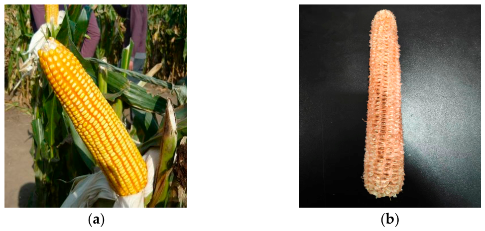
In this experiment, the maize variety used was Zhengdan 958, and its morphological structure is shown in Figure 1. All test maize samples were at the physiological maturity stage. The moisture content of maize kernels was measured before the test, and relevant morphological and physical parameters, including standard deviation, are summarized in Table 1.

2.2. Threshing Device

2.2.1. Overall Design Scheme

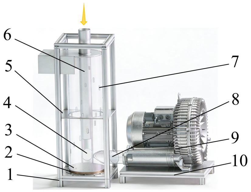
Based on the application of existing pneumatic conveying technology in maize transportation [31], airflow can realize non-destructive directional delivery of corn ears. This study further extends the principle of pneumatic conveying from simple material transportation to the driving stage of threshing process. Combined with the drag force model and collision theory in fluid mechanics, the force characteristics and motion rules of corn ears in vortex flow field are systematically analyzed. The vortex airflow-driven adaptive threshing device for high-moisture maize is shown in Figure 2, which mainly consists of the frame, vortex airflow threshing unit, high-pressure vortex fan, and feeding device. The overall frame is assembled with 40 × 40 aluminum profiles. The vortex threshing cylinder is fabricated from transparent acrylic material to facilitate internal motion observation and high-speed photographic recording. The air inlet pipe diameter is 105 mm. The matched vortex fan delivers a rated air flow of 1050 m3/h with a maximum vacuum of −340 mbar and maximum positive static pressure of 460 mbar, and the flexible collision protrusions inside the cylinder are made of wear-resistant elastic rubber.
(1)
Silicone protrusions are evenly arranged on the inner wall of the threshing cylinder to stabilize airflow. The silicone protrusions are arranged in two patterns. From the air inlet to the gas-solid separation outlet, the protrusions are helically distributed on the inner wall to guide the spiral upward movement of corn ears under vortex airflow and boost threshing performance. Six protrusions are uniformly mounted on the circular surface 500 mm above the bottom to increase collision frequency.
(2)
The highest point of the curved flow guide base at the bottom of the threshing chamber is level with the center of the air inlet. This structure enables corn ears to enter the chamber at varying heights and avoids material jamming. The central through hole of the base accommodates the vortex-core feeding pipe, functioning to facilitate material transition and supporting fixation.
(3)
The high-pressure vortex fan supplies high-pressure and large-flow airflow to form a stable vortex field, acting as the power source of the system.

2.2.2. Equipment Operation Process

During equipment operation, the vortex fan is activated first to produce continuous high-pressure airflow. This airflow flows into the cylindrical threshing cavity and forms a circulating vortex flow field inside the chamber. Maize ears are loaded into the unit via the top feed inlet. Guided by gravity and incoming airflow, ears descend to the bottom of the cylinder and slide onto the inclined guiding pedestal before entering the main vortex threshing zone. Spiral silicone protrusions are fixed on the inner cylinder wall, aligned along the travel path of maize ears. Inside the chamber, vortex airflow pushes maize ears to move upward in a spiral path against the wall, where repeated contact occurs between ears and silicone protrusions. Ears shift toward the central feed pipe after trajectory disturbance, strike the protrusions on the central pipe surface, and drift back to the outer cylinder wall to create cyclic reciprocating contact. All maize ears spin continuously as they circulate within the chamber. As airflow energy weakens with rising height, upward supporting force acting on maize ears gradually reduces. Once gravitational force dominates, incompletely threshed ears sink back to the chamber bottom and circulate through the contact cycle again. After sufficient repeated circulation, fully stripped maize cobs are carried upward by residual airflow to the upper outlet and discharged out of the device to finish the whole operating cycle.

2.2.3. Determination of Vortex Threshing Chamber Parameters

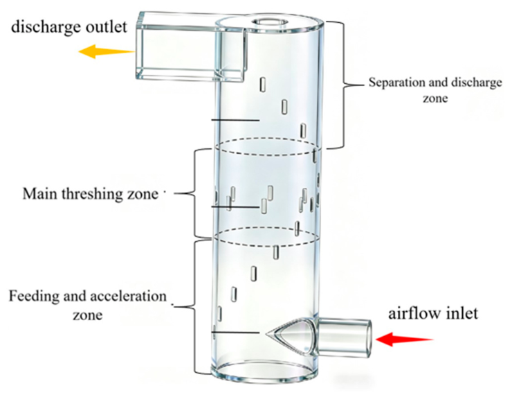
The structure of the vortex threshing chamber is shown in Figure 3. From bottom to top, the chamber can be divided into three functional zones: the feeding and acceleration zone, the primary threshing zone, and the separation and discharge zone.
In the design of the vortex threshing chamber, its diameter needs to balance two factors. First, a sufficiently large centrifugal acceleration is required to ensure that maize ears can closely attach to the chamber wall. The required diameter of the vortex threshing chamber can be calculated according to Formula (1).
a c = v θ 2 ( D C / 2 )
In the formula,  a c is the centrifugal acceleration of maize ear (m/s2); V θ represents the tangential airflow velocity (m/s); and D c stands for the inner diameter of the vortex threshing chamber (m).
The motion energy of maize ears in the vortex airflow field is mainly derived from the work performed by the airflow drag force. The airflow drag force F d acting on maize ears can be expressed as:
F d = 1 2 C d ρ A p ( v g v e ) 2
In the formula,  C d is the drag coefficient;  ρ  is the air density (kg/m3);  A p represents the projected area of the unthreshed maize ear on the plane perpendicular to the relative velocity vector between airflow and maize ear (m2); V g is the airflow velocity (m/s); and V e is the maize velocity (m/s). The formula describes the drag force generated by the relative motion between fluid and solid materials, which is independent of the overall airflow direction. By calculating the projected area perpendicular to the instantaneous relative velocity vector, the error caused by spiral airflow can be effectively reduced. The stable airflow environment in the threshing chamber also meets the application conditions of this formula.
The instantaneous power obtained by the maize from the airflow is given by:
P = F d · v e = 1 2 C d ρ A p ( v g v e ) 2 · v e
When the airflow velocity V g is much larger than the moving velocity V e of the maize ears, the maize ears are accelerated by the airflow. As V e approaches V g , the drag force decreases and the energy transfer tends to equilibrium. In the vortex flow field, the tangential component of the airflow continuously provides angular momentum to maize ears and maintains their spiral upward motion along the cylinder wall.
Airflow enters the vortex threshing chamber in the tangential direction and forms a vortex flow field. Maize ears acquire a tangential velocity V t under the action of airflow drag force. The centrifugal force F c borne by the ears determines whether they can move closely against the cylinder wall, which depends on whether the centrifugal force is sufficient to overcome the radial pulsation of the airflow and the component of gravity. According to the vortex flow field theory, the tangential velocity V t is correlated with the airflow inlet velocity V i n and the cylinder diameter D c .
v t = v i n D i n D c ϕ
In the formula,  D i n is the equivalent diameter of the air inlet (m), and  φ is the vortex flow field retention coefficient (typically ranging from 0.6 to 0.8).
To ensure maize ears achieve stable wall-attached rotational motion, the condition F c F m i n must be satisfied, where F m i n is the minimum centrifugal force required to maintain wall attachment. Secondly, excessive diameter should be avoided to prevent severe attenuation of airflow velocity. The Stokes number must be greater than a critical value to ensure that maize ears can reach the wall surface. By calculating the equivalent diameter D e of maize ears and the wind velocity inside the vortex threshing chamber, the determined diameter of the vortex threshing chamber is D c = 320 mm. In the length design, sufficient residence time must be guaranteed for maize ears to undergo multiple collisions. The axial motion of maize ears inside the vortex threshing chamber is determined by the combined effect of the airflow axial velocity V a and the self-gravity of maize ears. The axial motion equation of maize ears in the airflow can be simplified as:
m e d v a d t = F d , a m e g
In the formula, m e is the mass of a single maize ear (kg); v a is the axial velocity of maize ear (m/s); t denotes time (s); F d , a is the axial component of airflow drag force (N); g is the gravitational acceleration (9.81 m/s2). V g , a is the axial component of airflow velocity. When F d , a > m e g , the ear is transported upward by the airflow; when F d , a < m e g , the maize descends. In Equation (6), the effective travel distance of the maize ear in a single upward cycle refers to the axial moving distance within the effective threshing zone of the vortex chamber. It excludes the idle travel in the feeding zone and discharge zone, and only counts the running distance of maize ears in the core working area where flexible collision and grain shedding occur. The effective threshing time T s of an maize within the cylinder depends on the number of reciprocating cycles in the suspension zone:
T s = i = 1 n ( 2 L i v a , i )
In the formula, L i is the effective travel distance of the maize during a single upward cycle (m); V a , i is the average axial velocity during that cycle (m/s). The cylinder length L must be designed to ensure that, under the specified airflow parameters, the cumulative residence time T s of the maize is sufficient to achieve complete threshing. In this design, L is set to 1200 mm. The geometric parameter is determined based on the average dimension of test maize ears, ensuring enough space for single-ear spiral circulation and sufficient vertical height to realize repeated cyclic threshing. Combined with preliminary flow field simulations, the average residence time of ears ranges from 3.5 to 5.0 s, which meets the requirements for threshing efficiency.

2.2.4. Dynamic Analysis of the Maize Ear Threshing Process

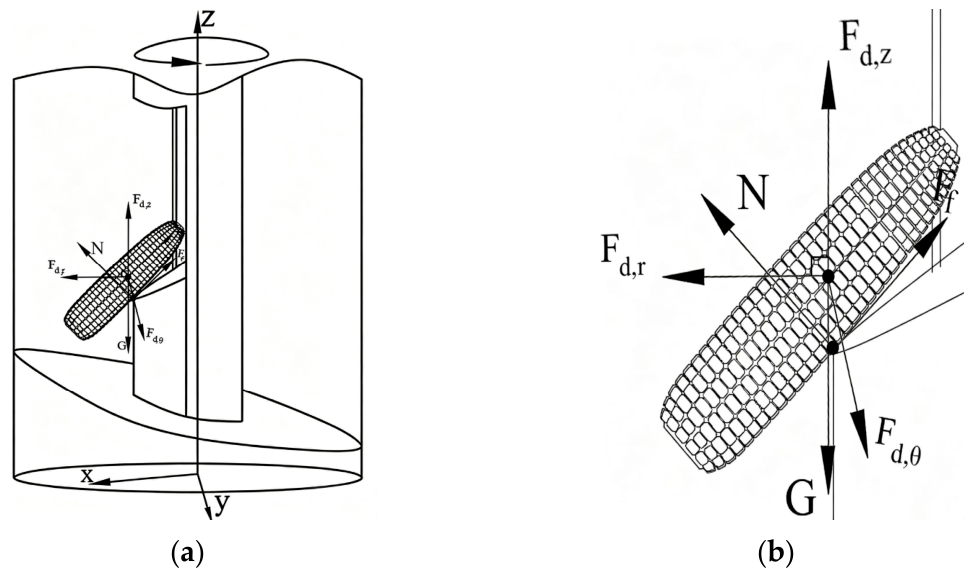
At the instant when maize ears separate from the inclined feeding base and enter the annular region at the bottom of the threshing cylinder, their velocity approaches zero and stable wall-attached motion has not yet been formed. The forces acting at this stage can be simplified to be dominated by gravity and airflow drag force, as shown in Figure 4.
At the initial moment, the tangential velocity and centrifugal force of maize ears are negligible; the radial velocity is extremely small, and the magnitude of the Coriolis force is far lower than the drag force, thus it is neglected. An arc-shaped flow guiding base is arranged at the bottom of the threshing chamber, and its highest point is flush with the center of the tangential air inlet pipe. Maize ears fall onto this highest point from the feeding chute. At this moment, the high-speed airflow generated by tangential air intake is guided by the arc surface, producing local flow acceleration and wall attachment effect on the base surface, which enhances the airflow drag force in the near-wall region. When the airflow passes over the highest point of the arc surface, it exerts a slant downward thrust on the maize ears, making them roll down along the arc surface naturally and gradually gain tangential and axial velocities. As the maize ears leave the highest point and enter the concave area of the arc surface, the acting area of the airflow on the ears increases, further enhancing the drag force. In a very short time, the maize ears achieve synchronous startup from static state to rotation, ascending and wall attachment, providing initial conditions for the subsequent spiral motion.
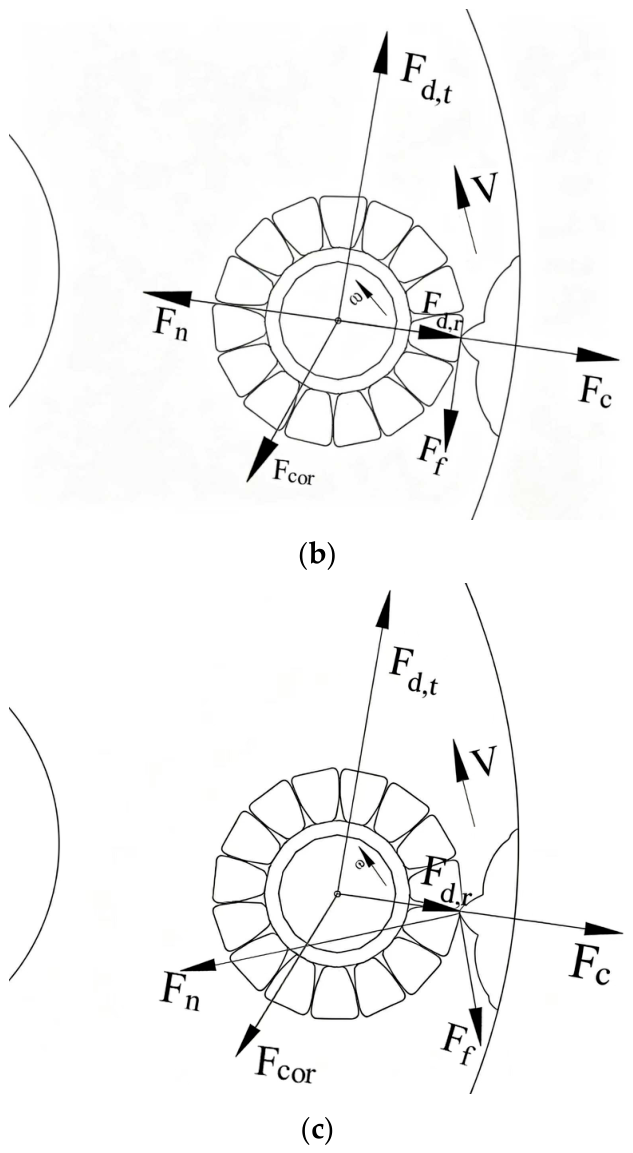
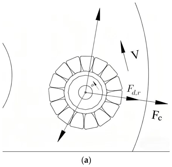
Inside the vortex threshing chamber, the motion of maize ears is dominated by tangential rotation and radial wall attachment. The force state is divided into three scenarios: the non-collision stage, the collision stage, and the state of being embedded in grain gaps. The corresponding force analysis is shown in Figure 5.
In the non-collision stage, maize ears are subjected to centrifugal force, the tangential and radial components of airflow drag force, and the Coriolis force. F d , t provides tangential driving force, while F d , r regulates the radial position of maize ears. The Coriolis force F c o r deflects maize ears and changes the force direction acting on grains, avoiding sustained unidirectional force loading. During the collision stage, the normal supporting force F n from the wall dominates instantaneously, and the friction force F f decelerates the maize ear in the tangential direction. Under radial displacement, the Coriolis force Fcor induces tangential deflection and adjusts the contact angle. This enables the impact force to act effectively on the grain gaps and applies alternating loads to promote fatigue fracture of grain attachment pedicels. The apex of the silica gel protrusion embeds into the grain gaps and generates concentrated stress. When the stress exceeds the connection strength between grains and ear pedicels, the grains are shed off [32]. The Coriolis force introduces multi-directional loading to accelerate fatigue damage of grain pedicels. The flexible protrusions reduce the peak value of normal supporting force F n and extend the force acting duration, which guarantees sufficient threshing energy while avoiding macroscopic grain breakage.
After threshing is completed, corn cobs and grains rise to the gas-solid separation outlet at the top of the threshing cylinder along with the airflow. The mass and density of corn cobs decrease after threshing, while grains feature a small equivalent diameter and low suspension velocity. The axial drag force acting on both corn cobs and grains is much greater than their self-gravity. Consequently, they accelerate upward and depart from the vortex threshing chamber. Due to the difference in aerodynamic characteristics between corn cobs and grains, natural separation can be achieved under the airflow velocity at the outlet, and both are discharged orderly through the gas-solid separation outlet.

2.2.5. Design of the Vortex-Core Feed Tube

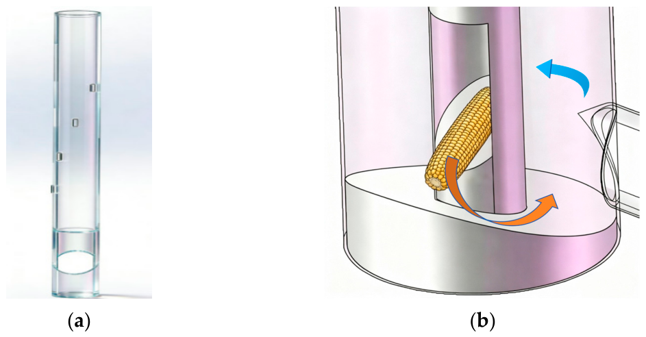
In the overall design of the threshing device, a vortex-center feeding pipe runs through the center of the vortex threshing chamber. Its structure is shown in Figure 6, in which Figure 6a presents the overall structural drawing of the vortex-center feeding pipe, and Figure 6b is a schematic diagram illustrating the entry process of maize ears into the vortex threshing chamber from the bottom of the vortex-center feeding pipe.
This design serves two main functions. The first function is to act as a structural mandrel, which reduces the actual annular working volume of the vortex threshing chamber. With a smaller cross-sectional area of the annular space, under the same air intake flow rate, it can effectively increase the air velocity and rotation intensity, making it easier to form a stable and strong vortex flow field, thereby providing more efficient initial driving energy for the corn ears. The second function is to act as a functional feeding channel. Corn ears are fed axially through the hollow par and exit through the opening at the bottom of the vortex-center feeding pipe. A slope is provided in the hollow area at the opening, allowing the corn to directly reach the starting end of the threshing zone. The width of the annular gap between the vortex threshing chamber and the vortex-center feeding pipe must be larger than the diameter of the large end of the corn ear, with a safety margin left to prevent jamming.
δ = D C D t 2 > k · d m a x
In the formula, δ is the width of the annular gap (m); D c is the inner diameter of the vortex threshing chamber (m); D t is the outer diameter of the vortex-core feed tube (m); d m a x is the diameter of the large end of the corn ear; and k is the safety factor, taken as 1.5, which is used to compensate for the inclination of the corn ear’s posture, dimensional variation, and dynamic jump during movement. Through calculation, the diameter of the vortex-center feeding pipe is designed to be 100 mm.

2.2.6. Design and Arrangement of Threshing Elements

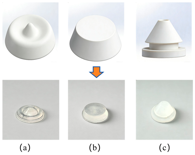
To achieve low-damage threshing, this device adopts silica gel as the base material of the threshing elements. The inherent high elasticity and damping characteristics of silica gel enable it to effectively buffer the impact through its own deformation and extend the contact time when colliding with corn ears, thereby reducing the peak value of instantaneous impact stress. This design conforms to the mechanical design principle of flexible collision, and its impact force, kneading force, and blocking rate are significantly lower than those of traditional rigid elements [33]. Three types of silica gel threshing elements are designed, namely, the pointed-ring composite type, the frustum type, and the pointed-top cylindrical type, whose structures are shown in Figure 7. The specific dimensions of each threshing element are as follows: (a) pointed-ring composite protrusion: total height 8 mm, base outer diameter 16 mm, tip cone height 5 mm; (b) truncated cone protrusion: top diameter 10 mm, bottom diameter 16 mm, overall height 14 mm; and (c) pointed cylindrical protrusion: cylinder diameter 14 mm, total height 12 mm, tip cone height 6 mm. Through preliminary experiments, the pointed-ring composite structure is optimized and selected. Its pointed top can be embedded into the gaps between grains to concentrate the acting force and promote grain shedding; the annular base disperses the contact stress to avoid local breakage.
The protrusions are arranged along the inner wall of the threshing cylinder in a helical array with a constant lead. Denoting the helix lead as S and the cylinder diameter as D c = 320 mm, the helix angle α satisfies the following relationship:
The protrusions are arranged in an array along the inner wall of the threshing cylinder according to an equi-lead helix. Let the helix lead be S and the cylinder diameter D c = 320 mm, then the helix angle α satisfies:
tan α = S π D c
The number of uniformly distributed protrusions in a single circle is N , and the circumferential angular spacing Δ θ = 360 ° N . The axial spacing between adjacent protrusions Δ h = S N . The corn ears move at a tangential velocity v t and an axial velocity v a under the action of airflow drag force. According to the spiral angle of the corn ear movement β = arctan ( v a v t ) , let α β to maximize momentum exchange, and take Δ h < 186   m m . Setting S = 600   m m , we get α 30.5 ° .

2.3. Experimental Design and Evaluation Indices

2.3.1. Experimental Objective

This study selects three key influencing factors, namely, the circumferential angular spacing of flexible threshing elements, tangential airflow velocity, and feed rate, to explore their combined effects on maize threshing performance. The circumferential angular spacing is adopted to quantitatively characterize the layout density of threshing elements. The range of each factor is determined through preliminary tests: feed rate from 0.18 to 0.90 kg/s; circumferential angular spacing of threshing elements from 10° to 30°; and tangential velocity from 36 to 52 m/s. A quadratic orthogonal rotational combination design is adopted to systematically analyze the individual effects and interaction effects of the three factors on threshing efficiency. The threshing elements are uniformly distributed on the same cross-section of the vortex threshing chamber. To clearly characterize the density of threshing elements, the circumferential angular spacing is adopted to represent the element density. The circumferential angular spacing of uniformly arranged threshing elements is determined by the number of elements per circular layout, and the calculation rule has been described in the previous section. The optimal range for each factor was determined as follows: feed rate ranging from 0.18 to 0.90 kg/s; circumferential angular spacing of threshing elements from 10°to 30°; and tangential velocity from 36 to 52 m/s. To further elucidate the combined effects of key threshing parameters on threshing performance, a quadratic orthogonal rotation combination design was employed to systematically investigate the influence of individual factors and their interactions on threshing efficiency.

2.3.2. Experimental Methods

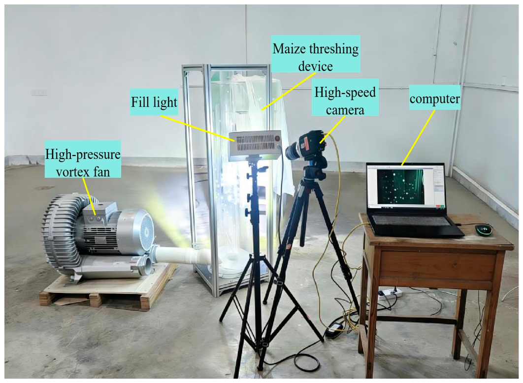
This study adopted the regression orthogonal rotational composite design method to systematically carry out performance experiments on maize threshing. The experiments were carried out on a self-developed threshing test bench (as shown in Figure 8), with circumferential angular spacing A, tangential velocity B, and feeding rate C selected as the core experimental factors. Since the maize breakage rate of the test device is nearly zero, the breakage rate was not taken as an experimental observation index, and only the maize threshing rate was selected as the performance evaluation index of the threshing device.
Before the test, unified pretreatment was performed on maize ears. Severely mildewed and deformed ears were eliminated, and their initial moisture content was measured by a halogen moisture analyzer. Maize ears were manually fed into the threshing device at a constant feeding speed for each test. To maintain uniform feeding conditions, we pre-grouped maize ears with consistent single-ear mass. One maize ear was fed into the chamber at fixed equal time intervals by a single trained operator throughout each trial group. The feeding interval was strictly controlled with a stopwatch, ensuring a stable and constant mass feed rate for every test condition. The density and arrangement of threshing elements were adjusted to the target values before each experiment.
During the test, the high-pressure vortex fan was first turned on and run until stable operation was achieved. Maize ears were then fed into the device through the central circular pipe. After the threshing process was completely finished, the threshed materials and residual materials were collected in sequence. After cleaning the threshed materials, a combination of standard sieve screening and manual sorting was adopted to separately measure the mass of fully threshed grains, damaged grains, and incompletely threshed cobs, and then each evaluation index was calculated accordingly. Each group of experiments was repeated three times, and the arithmetic mean value was adopted for the results to reduce random errors. All experimental operations were strictly implemented in accordance with GB/T 5982-2017 Test Methods for Threshers, and the environmental conditions were kept consistent throughout the tests. The experimental design consisted of 17 treatment groups. The levels of each factor were determined based on the results of the previous single-factor preliminary test, and the specific coding scheme is shown in Table 2. Through this design, this study aims to systematically analyze the quantitative effects of various factors and their interactions on maize threshing effect and to provide a theoretical basis for parameter optimization.

2.3.3. Performance Evaluation Indicators

It was found in the preliminary test that within the parameter range set in this experiment, the breakage rate of maize grains was nearly zero, which lacked discrimination as an evaluation index. Therefore, in the formal experiment, the grain breakage rate was only recorded as an auxiliary observation index. However, to further verify the impact of the threshing process on grains, this study introduced a dyeing detection method for microcracks on the grain surface to evaluate threshing damage at the microscale. In accordance with the national standard GB/T 21962-2020 Maize Threshers and relevant research methods, the threshing rate is selected as the sole core index for evaluating operational performance. Its definition and calculation method are given as follows.
(1)
Microcrack detection on kernels
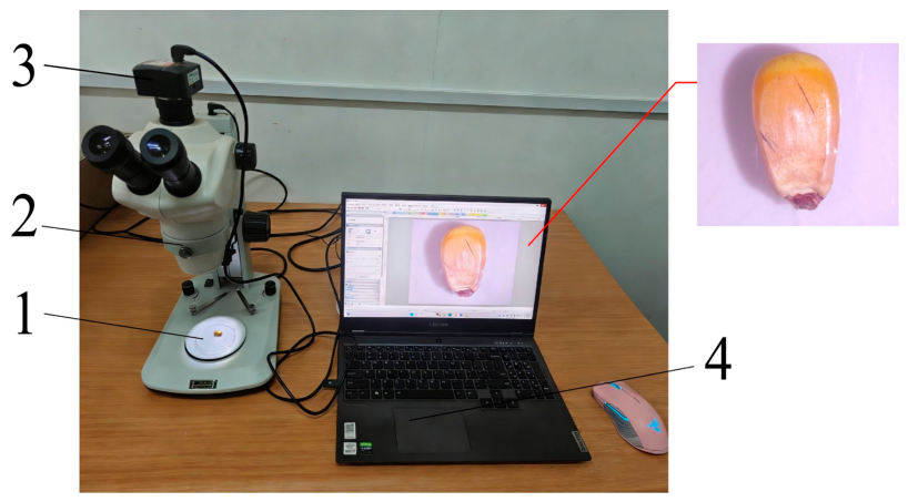
To evaluate the micro-damage caused to grains during the threshing process, a dyeing detection method was used to detect microcracks on the grain surface. Specifically, the black ink dyeing method was adopted to detect surface microcracks on the intact grains after threshing. Thirty intact grains with no macroscopic damage were randomly selected from the threshed grains obtained in each test. The samples were immersed in a 0.5% mass-to-volume black ink solution and kept stationary at room temperature for 15 min, allowing the dye to penetrate into potential surface microcracks under capillary action. The grains were taken out and rinsed slowly with running distilled water for 30 s to remove the dye attached to the surface. After blotting the surface moisture with filter paper, the grains were placed on a white background plate and observed and photographed using a Stemi-508 stereomicroscope, as shown in Figure 9. If open microcracks exist, distinct black traces will remain within the cracks.
The number of kernels exhibiting black cracks was recorded, and the microcrack incidence rate was calculated using the following formula:
y 1 = W s W i × 100 %
In the formula, y 1 is the microcrack incidence rate (%); W s is the number of kernels with microcracks; and W i is the total number of kernels examined.
Meanwhile, two control groups were set up: negative control Group A: intact maize grains carefully shelled manually; positive control Group B: intact grains processed by a traditional spike-tooth drum thresher.
(2)
Threshing efficiency
The maize threshing rate is defined as the percentage of the mass of grains separated from the corn cob relative to the theoretical total grain mass contained in the maize ears used in the test. This index is mainly used to evaluate the threshing sufficiency and separation capacity of the threshing device. After each test, the total mass of all threshed grains collected from the gas-solid separation outlet was weighed and recorded. Meanwhile, all unseparated grains remaining on the cobs at the discharge outlet and inside the device were carefully collected and manually threshed, and their mass was weighed. The maize threshing rate was calculated by the following formula:
y 2 = W b W z × 100 %
In the formula, y 2 is the threshing efficiency (%); W b is the mass of threshed kernels (kg); and W z is the mass of kernels remaining on the cobs (kg).
All indices were determined based on the average values of repeated tests to ensure the reliability of experimental results. Each group of parameters was repeated three times, and the mean value and standard deviation of each index were calculated for subsequent comparative analysis.

3. Results and Discussion

3.1. Experimental Design and Results

The experimental scheme and corresponding results are presented in Table 3. Among them, x1, x2, and x3 correspond to the coded values of factors A, B, and C, respectively.

3.2. Variance Analysis of the Regression Model

An analysis of variance (ANOVA) was performed on the threshing rate, and the results are listed in Table 4. It can be seen from Table 4 that the model p < 0.0001 , indicating that the experimental model is highly significant. The lack-of-fit term yields p > 0.05 , indicating it is insignificant. The coefficient of determination R 2  of the model is 0.9928, reflecting a high fitting precision. This demonstrates that the model can accurately predict the experimental index. The adjusted R 2  reaches 0.9837 and the predicted R 2 is 0.9559; the standard deviation of the regression model equals 0.79. Residual analysis shows that residual points follow a random distribution without obvious systematic deviation or clustering trend, which verifies the validity and stability of the established quadratic regression model.
Multiple regression analysis was carried out on the experimental data using Design-Expert 10.0.7. The p values of the linear terms x 1 , x 2 , x 3 , interaction terms x 1 x 2 , x 1 x 3 , x 2 x 3 , and quadratic terms  x 1 2 , x 2 2 , x 3 2 were all less than 0.05, indicating that all these terms had significant effects on the threshing rate. Based on these significant terms, the regression equation of the threshing rate was established as follows:
y 2 = 95.64 + 2.16 x 1 + 1.38 x 2 + 2.36 x 3 + 3.05 x 1 x 2 + 1.83 x 1 x 3 + 3.60 x 2 x 3 4.76   x 1 2 4.73 x 2 2 6.51 x 3 2
The test results of partial regression coefficients of the regression equation [34] showed that the primary and secondary order of the influences of various factors on the maize threshing rate y 2 was feeding rate, circumferential angular spacing, and tangential velocity.

3.3. Force Analysis of Maize Threshing Using High-Speed Photography

3.3.1. Maize Ear Movement Trajectory and Dynamic Characteristics

To reveal the internal mechanism of flexible collision threshing driven by swirling airflow, a high-speed photography system was adopted in this study to visually record the threshing process, with a frame rate of 1000 fps and a resolution of 1280 × 720 [35]. By tracking and analyzing the motion trajectory, posture variation of ears in the threshing cylinder, as well as the dynamic behavior of grains at the moment of detachment, direct evidence is provided for the airflow-driven ear movement and low-damage threshing mechanism via flexible collision proposed in this study. High-speed photography captures the complete spiral circulation and reciprocating collision trajectory of maize ears inside the vortex chamber, providing intuitive visual evidence for analyzing material movement patterns.
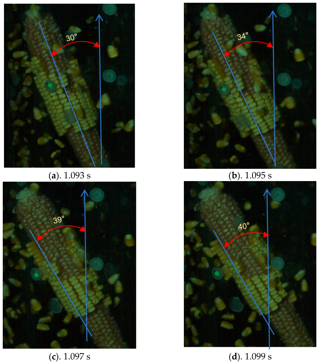
In the flow field, maize ears are mainly subjected to the combined effects of airflow drag force, centrifugal force, and wall collision reaction force, and their motion presents complex composite characteristics of revolution, rotation, and axial movement. As shown in Figure 10a–d, the edge line of the central cylinder was selected as the fixed reference line in the images, and a specific row on the maize ear was chosen as the observation object. Two-dimensional image analysis based on high-speed photography shows that the ear posture changes sharply at the moment of collision. The included angle between the observed axis and the reference line of the central cylinder wall changes by θ 10 ° within T = 0.006   s , accompanied by an instantaneous increase in the rotational angular velocity. The included angle was quantified using built-in angle measurement tools in high-speed camera post-processing software, with the vertical central axis of the vortex cylinder set as the fixed reference baseline. This representative case is adopted to qualitatively interpret the posture change mechanism of maize ears upon collision. The posture adjustment and rotation of maize ears subject the connection between grains and pedicels to complex alternating stress, thereby promoting fatigue fracture at the grain stalk junction. In the collision-free section, the maize ear moves at a constant or accelerated speed under the axial component force of airflow. At the moment of colliding with the spirally arranged flexible protrusions, the axial velocity decreases sharply or even reverses, producing a retardation and rebound effect. This effectively prolongs the residence time of maize ears within the effective threshing zone.

3.3.2. Movement Trajectory and Dynamic Characteristics of Maize Grains During Threshing

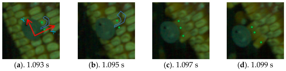
Figure 11 presents representative time nodes during the threshing process, illustrating the whole motion process from initial stress deformation to final grain detachment. The time is calibrated by taking the trigger moment of the high-speed camera as the zero point.
The core of threshing lies in inducing drastic overall posture changes of the ear, which generates concentrated stress at the grain–pedicel interface and facilitates fatigue or brittle fracture. The tip protrusions of threshing elements act on the intra-row gaps of maize grains. As the maize ear continues to move, the force exerted by the tip protrusions causes grain displacement. This force can be decomposed into two component forces in the X and Y directions. The acted grains include the two marked grains in Figure 11a and the three detached marked grains in Figure 11d. By observing the gaps between the marked grains and adjacent grains in Figure 11a,b, it is found that the gaps gradually expand while the grains do not detach immediately. The force exerted by the threshing elements acts continuously on the grains and promotes their fatigue fracture. Grain detachment in Figure 11c occurs when the force exerted by the threshing element on the grain exceeds the resultant force of the pedicel binding force, as well as the extrusion and friction forces among adjacent grains. Thereafter, the maize ear keeps moving and continuously collides with the threshing elements, achieving the final threshing effect.

3.3.3. Movement Characteristics of Typical Corn Grains During Threshing

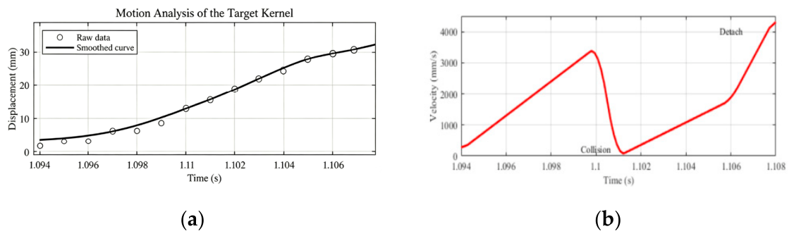
The following description details the data processing workflow used to construct the velocity distribution cloud diagram shown in Figure 12. As shown in Figure 11d, the lowest marked maize grain serves as the reference grain. Its motion coordinates were continuously recorded for 15 frames starting from 1,092,792 μs. Based on the coordinate data, the motion trajectory was fitted using MATLAB R2021b software, yielding the fitting curve shown in Figure 12. Figure 12a displays the complete displacement trajectory of one representative single maize ear covering its full cycle of motion and collision inside the threshing chamber. This ear was selected as a typical sample with intact and fully captured movement footage to intuitively demonstrate the whole threshing procedure.
As shown in Figure 12a, the displacement of the grain increases monotonically with time and presents a continuous variation, which fully reflects the entire detachment process of the grain from the maize ear. Before the grain detaches from the ear, it accelerates slowly along with the ear, and its velocity rises steadily. Upon collision with the flexible threshing unit, the grain velocity drops sharply to nearly zero while still remaining connected to the pedicel without immediate detachment. Subsequently, the maize ear continues to accelerate and drives the grain to increase its velocity synchronously. When the grain separates from the pedicel, it accelerates rapidly under the action of airflow drag force due to its small mass. The displacement contour distribution of maize ears in Figure 12a was differentiated with respect to time to calculate instantaneous velocity data, which was used to generate the velocity cloud map in Figure 12b. The variation of grain velocity throughout the whole process is illustrated in Figure 12b. This process fully presents the motion variation of grains in the adaptive threshing behavior.

3.4. Analysis of the Influence of Factors on Performance Indicators

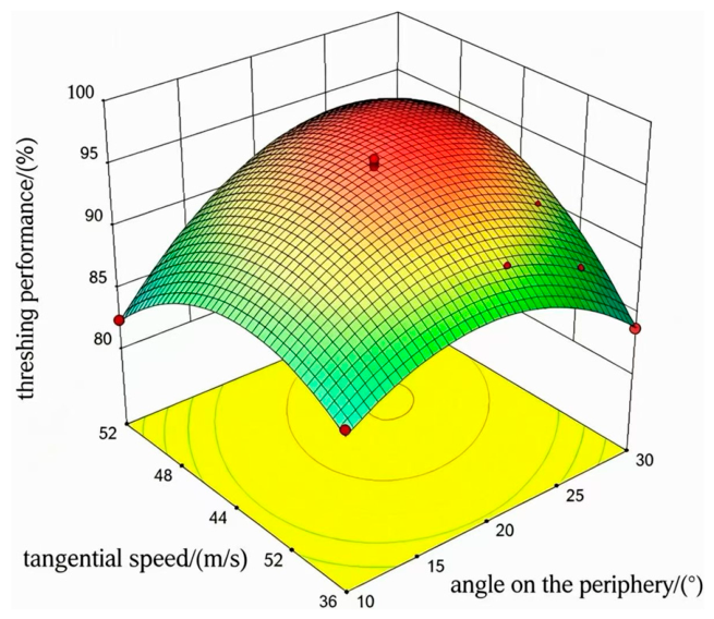
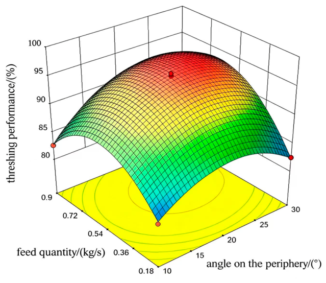
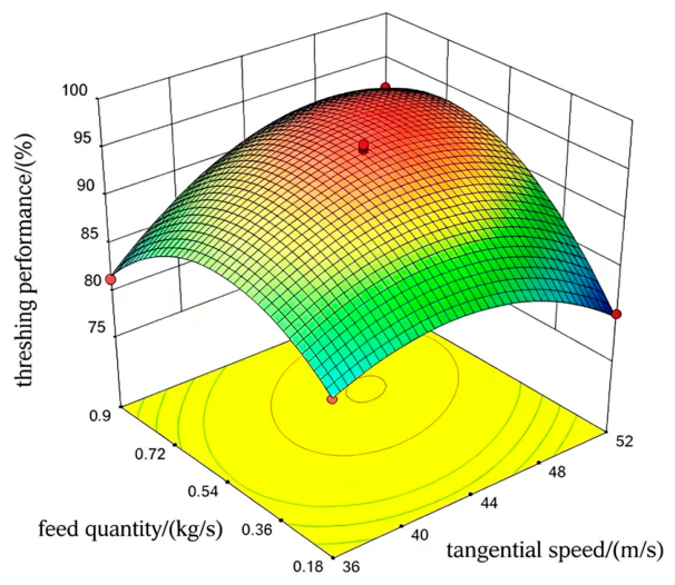
The influence effects of various factors on the threshing rate can be intuitively presented via 3D response surface plots. All response surfaces exhibit a downward-opening paraboloid shape, indicating that within the test range, the threshing rate first increases and then decreases with the variation of each factor level. There exists an optimal parameter combination to maximize the threshing rate. The spatial arrangement of maize grains on the ear follows a specific block masonry law, and complex force chain networks are formed through contact among adjacent grains [36]. In the axial direction, when the action lines of contact forces between maize grains lie within the friction angle range, the grains in the force chain are in a self-locking state and form strong force chains. Such force chains can withstand large tangential external forces and are not easy to break. Due to the large friction coefficient and strong compressive deformation capacity of the grain ventral surface, the force chain maintains high stability. In the transverse direction, the orientation of the force chain is consistent with the transmission direction of the grain masonry arrangement, presenting multi-directional force transfer. There is no self-locking effect among grains, and such force chains belong to weak force chains. The side surface of maize grains is smooth with a low friction coefficient and weak capacity to bear axial force; hence, a small axial force is sufficient to break the force chain. The above force chain characteristics determine that the optimal threshing strategy should prioritize applying force in the transverse direction. Taking advantage of the easy fracture of weak force chains enables low-energy-consumption threshing. Meanwhile, excessive axial force should be avoided to prevent triggering the self-locking effect of axial strong force chains, which would otherwise increase the difficulty of threshing.
Figure 13 shows the response surface of the interaction between circumferential angular spacing and tangential velocity on threshing efficiency at a feed rate of 0.54 kg/s. The transverse force chains of maize ears belong to weak force chains. The grain side surface is smooth, with a low friction coefficient and poor capacity to bear axial force. Applying force in the circumferential direction is the most efficient way to break the force chains. When the circumferential angular spacing is large, the density of threshing elements is low, and the number of collisions between the rotating ear and threshing elements per revolution is reduced. Since the transverse weak force chains transfer forces in multiple directions, repeated force application from multiple angles is required for complete failure. When the number of effective collisions per rotation is insufficient, the weak force chains in some orientations cannot be fully acted upon, making the grains in these rows difficult to detach and resulting in the reduction of the threshing rate. When the circumferential angular spacing is small, the layout density of threshing elements increases, and the collision frequency between corn ears and threshing elements per revolution rises significantly. High-frequency multi-directional collisions can comprehensively disrupt the transverse weak force chain network, which is conducive to improving the threshing rate. However, if the tangential velocity is excessively low, the collision energy is insufficient to overcome the initial contact force between grains in the weak force chains. A large number of low-energy collisions become ineffective, leading to a reduction in the threshing rate as well. Therefore, the circumferential angular spacing and tangential velocity need to be coordinately matched. A sufficiently high tangential velocity provides the energy required to break the weak force chains, while moderate circumferential angular spacing ensures comprehensive multi-directional collisions. The combined effect of the two can effectively disrupt the transverse force chain network and achieve a high threshing rate.
Figure 14 presents the response surface of the interaction between circumferential angular spacing and feed rate on threshing efficiency at a tangential velocity of 44 m/s. The force chains of maize ears form a three-dimensional spatial network, in which each grain in the radial direction intersects perpendicularly with the transverse and longitudinal force chains. Destruction of this three-dimensional network requires a sufficient and uniform impact on the ear surface exerted by threshing elements. When the feed rate is excessively low, maize ears are sparsely distributed in the threshing chamber, with a fast axial moving speed and a short residence time. When the circumferential angular spacing is large, maize ears collide with threshing elements only a few times within a limited time. The three-dimensional force chain network is impacted at merely a few points without overall collapse, leaving a large number of grains undetached. When the feed rate is excessively high, maize ears shield and collide with one another frequently, forming a contact state dominated by ear-to-ear interaction. When the feed rate is excessively high, maize ears shield and collide with one another frequently, forming a contact state dominated by ear-to-ear interaction. Random collisions between maize ears are non-directional and low-efficiency impacts, which can hardly cause systematic damage to the force chain network of target ears. Meanwhile, the dense ear group occupies the flow channel space, reducing the effective contact between individual ears and threshing elements. This leads to an incomplete breakdown of the three-dimensional force chain network and a decline in the threshing rate. An appropriate feed rate can not only ensure a sufficient residence time of maize ears, but also avoid mutual interference among ears, enabling threshing elements to exert a sufficient and ordered impact on the force chain network of each ear.
Figure 15 shows the response surface of the interaction between feed rate and tangential velocity on threshing efficiency when the circumferential angular spacing of threshing elements is 20°. The axial force chains of maize ears possess a self-locking characteristic: when the line of action of the contact force between grains falls within the friction angle range, the grains in the force chain enter a self-locking state and form strong force chains, which can withstand large tangential external forces without fracture. Excess axial force acting on maize ears will instead trigger the self-locking effect, causing tighter extrusion between grains and further increasing the difficulty of threshing. When the tangential velocity is too low, the centrifugal force acquired by maize ears is insufficient to form stable wall-attached rotation. The ears remain in a floating state inside the cylinder, and their collision with threshing elements is dominated by axial sliding. This axial-dominated collision mode tends to trigger the self-locking effect of axial force chains, resulting in tighter extrusion between grains and thus being unfavorable to threshing. When the tangential velocity is excessively high, maize ears are rapidly pushed toward the outlet with an extremely short residence time. An excessively high tangential velocity also increases the axial velocity component, causing maize ears to rise rapidly while rotating at high speed. This likewise generates a considerable axial force, which may partially trigger the self-locking effect. Meanwhile, the effective threshing time becomes insufficient, resulting in a decreased threshing rate. Therefore, there exists an optimal tangential velocity range. Within this range, maize ears can acquire sufficient circumferential kinetic energy to break the transverse weak force chains, while excessive axial force that triggers self-locking of axial strong force chains is avoided, thereby realizing high-efficiency and low-damage threshing.

3.5. Parameter Optimization

Based on the response surface methodology analysis, taking the maximum threshing rate as the optimization objective, Design-Expert 10.0.7 software was adopted for numerical optimization of the quadratic regression model to determine the optimal level combination of each experimental factor. The optimization constraint conditions were set as follows:
{ max   y 2 s . t . { 10 < x 1 < 30 36 < x 2 < 52 0.18 < x 3 < 0.9
The software optimization results show that when the circumferential angle is 21.5°, the tangential velocity is 45.9 m/s, and the feed rate is 0.65 kg/s, the model predicts the maximum threshing rate with a predicted value of 96.5%. This parameter combination is regarded as the optimal working parameter of the maize threshing.

3.6. Validation Experiments

To verify the reliability and accuracy of the response surface optimization results, three groups of parallel validation experiments were carried out under the above optimal parameter combination. The experimental results are shown in Table 5. The average value was 96.1%, with a standard deviation of 1.21 and an average relative error of 0.90% between replicates. Minor experimental variability originates from slight differences in initial maize ear posture, confirming good test repeatability. The threshing rate was measured and averaged, and then compared with the model predicted value. The experimental results show that the measured average threshing rate under the optimal parameters is 96.1%. Compared with the model predicted value of 96.5%, the relative error is only 0.41%. The error is small, indicating that the established response surface model possesses high prediction accuracy and a good fitting effect. The optimized process parameters are authentic and reliable and can be adopted as the actual operating parameters of the threshing device.

3.7. Microcrack Analysis of Maize Kernels

The macroscopic crushing rate index indicates that under the optimal parameter combination, the grain crushing rate of the device is lower than 0.1%. To further explore whether the threshing process causes imperceptible microstructural damage to grains, the black ink staining method was adopted for detection, and the typical comparison results are shown in Figure 16.
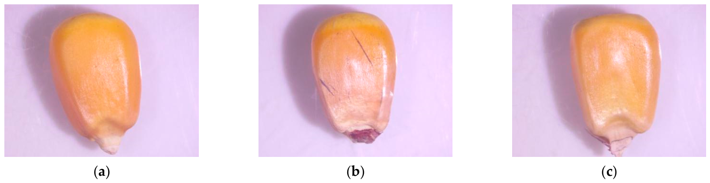
The results show that the grains in negative control Group A present almost no black traces on the surface, indicating that intact grains have no open cracks on their surface. In Group B (positive control), black reticular cracks appeared on the grain surface, especially in the endosperm region. This indicates that traditional rigid impact threshing causes obvious surface micro-damage, with the detection rate of microcracks exceeding 42%. For Group C grains threshed by the proposed device, most grain surfaces showed no difference from those in the negative control group; only a few grains presented scattered and short linear black marks near the stalk attachment site. Statistically, under the optimal process parameters, the microcrack detection rate is only 3.3%, with an extremely small crack size.
This result verifies the low-damage advantage of the airflow-driven and flexible impact threshing method from a microscopic perspective. Although the collision from the protrusions of flexible threshing elements can provide sufficient momentum to detach grains, it features a low peak contact stress and long action time, which effectively avoids the fracture of grain epidermis and internal structure caused by stress concentration. The integrity of grain microstructure is of great significance for ensuring the storage stability, germination rate, and subsequent processing quality of maize.

3.8. Discussion

The essential distinction between the proposed adaptive threshing mechanism and conventional forced threshing lies in the adaptive contact between the corn ear and the stationary adaptive element under airflow drive: when the contact force exceeds a threshold, the ear automatically deviates from its trajectory, avoiding rigid confrontation. High-speed photography confirmed the observability of this behavior. The anisotropy theory of the force chain network in corn ears provides a mechanical basis for optimizing threshing parameters. The transverse weak force chains are readily disrupted by circumferential collisions, whereas the axial strong force chains exhibit self-locking characteristics that should not be excessively excited.
The core advantage of the proposed device lies in nearly damage-free threshing, and the grain separation rate is adopted as the primary optimization indicator. Compared with existing threshing equipment, the vortex flexible collision structure achieves a high grain separation rate while greatly lowering kernel breakage. Compared with existing low-damage threshing technologies, the proposed device exhibits advantages in kernel breakage rate and microcrack detection rate. The key lies in the transition from forced impact to adaptive contact. Regarding structural design, the annular gap formed by the vortex threshing chamber and the central core tube enhances tangential velocity, the arc-shaped guiding base enables smooth startup of the ear, and the helical array ensures uniform collisions.
The limitations of this study lie in the fact that the working process can be applied to threshing theoretical research concerning other maize varieties after proper modification. This study lacks a detailed 3D flow field measurement and quantitative threshold of adaptive behavior. Future research will cover multi-variety tests, particle image velocimetry (PIV) measurement, and engineering prototype development.


4. Conclusions

This paper addresses the problems of high grain breakage rate and low threshing cleanliness during the threshing of high-moisture maize. Based on the coupling principle of vortex airflow driving and adaptive threshing, a novel maize ear threshing device is designed. Through theoretical analysis and experimental research, the influence laws of the circumferential angular spacing of threshing units, tangential velocity, and feed rate on threshing rate were revealed, and the optimal combination of operating parameters was obtained, realizing low-damage threshing of high-moisture-content maize ears.
(1)
Different from the traditional active impact threshing mode with rigid components, the proposed method realizes adaptive contact threshing. Driven by vortex airflow, maize ears move actively and collide with stationary flexible units gently. This working mode fundamentally avoids rigid violent impact, which is the key to achieving low-damage threshing for high-moisture maize.
(2)
The structural parameters of the vortex threshing chamber and flexible threshing elements were rationally determined. The designed chamber and central feed tube form an annular flow field that strengthens vortex airflow stability and airflow velocity. The spiral arrangement of silicone flexible protrusions ensures uniform multi-angle collision, which well matches the motion characteristics of maize ears and further improves threshing stability.
(3)
Feed rate, circumferential angular spacing, and tangential velocity all exert significant interactive effects on threshing performance. Among the three factors, feed rate shows the most prominent influence, followed by circumferential angular spacing and tangential velocity. The threshing rate presents a parabolic variation trend with each factor, indicating that a matched combination of parameters is essential to balance threshing efficiency and working stability.
(4)
The optimal operating parameters were obtained and verified experimentally. For Zhengdan 958 maize ears with a moisture content of 24.4~28.6%, the optimal parameter combination is as follows: circumferential angular spacing of 21.5°, tangential velocity of 45.9 m/s, and feed rate of 0.65 kg/s. The average threshing cleanliness measured by verification experiments was 96.1%, with a relative error of only 0.41% compared with the model predicted value of 96.5%. The microcrack detection rate is merely 3.3%, which is significantly superior to the traditional rigid threshing method.
Author Contributions

Conceptualization, X.L. and B.P.; methodology, X.L.; software, B.P.; validation, X.L., B.P. and R.S.; formal analysis, Y.L.; investigation, R.S.; resources, X.L.; data curation, B.P.; writing—original draft preparation, X.L. and B.P.; writing—review and editing, X.L. and B.P.; visualization, F.M.; supervision, J.P., H.Z. and H.W.; project administration, L.G., H.Z. and J.Z. funding acquisition, X.L. All authors have read and agreed to the published version of the manuscript.

Funding

This research was funded by the National Natural Science Foundation of China (52275245). It would not have been possible without the assistance of the postgraduate students on the research team. We are grateful for the support of the fund project and the research team members.

Institutional Review Board Statement

Not applicable.

Informed Consent Statement

Not applicable.

Data Availability Statement

The original contributions presented in the study are included in the article.

Acknowledgments

We thank all the editors and reviewers for their suggestions and comments.

Conflicts of Interest

The authors declare no conflicts of interest.

References

  1. Kailashkumar, E.B. Study of Different Kinds of Threshers & Factors Influencing Threshing of Crops: A Review. Int. J. Sci. Res. Dev. 2019, 6, 65–73. [Google Scholar]
  2. Looh, G.A.; Xie, F.; Wang, X.; Looh, A.N.; Hind, H. Grain kernel damage during threshing: A comprehensive review of theories and models. J. Agric. Eng. 2025, 56, 1674. [Google Scholar]
  3. Cui, C.; Yao, Y.; Lin, J.; Wang, F.; Jiang, W.; Li, X.; Zhao, B. Design of a Detection and Sorting System for Broken Corn Kernels with an Online Identification Method. Appl. Eng. Agric. 2025, 41, 83–95. [Google Scholar] [CrossRef]
  4. Gao, L.X.; Li, F.; Zhang, X.W.; Liu, X.; Jiao, W.P. Mechanism of Moisture Content Affect on Corn Seed Threshing. Trans. Chin. Soc. Agric. Mach. 2011, 42, 92–96. [Google Scholar]
  5. Ren, X.; Dai, F.; Zhao, W.; Shi, R.; Chen, J.; Chang, L. Progress in mechanized harvesting technologies and equipment for minor cereals: A review. Agriculture 2025, 15, 1576. [Google Scholar] [CrossRef]
  6. Pachanawan, A.; Chuan-Udom, S.; Doungpueng, K. Development of drums for an axial flow maize shelling unit. Eng. J. 2021, 25, 59–70. [Google Scholar] [CrossRef]
  7. Astanakulov, K.D.; Fozilov, G.; Kodirov, B.K.; Khudaev, I.; Shermukhamedov, K.; Umarova, F. Theoretical and experimental results of determination of the peeler-bar parameters of corn-thresher. IOP Conf. Ser. Earth Environ. Sci. 2020, 614, 012130. [Google Scholar] [CrossRef]
  8. Mingrui, L.; Yanchun, Y.; Yongkang, Z.; Xibin, L.; Dong, Y.; Duanyang, G. Design and Experiment of a Double Longitudinal Axial-Flow Corn Threshing Device for Large Feeding Capacity. INMATEH-Agric. Eng. 2025, 75, 527–538. [Google Scholar] [CrossRef]
  9. Fan, C.; Cui, T.; Zhang, D.; Qu, Z. Design of feeding head spiral angle longitudinal axis corn threshing separation device based on EDEM. In Proceedings of the 2019 ASABE Annual International Meeting, Boston, MA, USA, 7–10 July 2019; p. 1. [Google Scholar]
  10. Yue, D.; Wang, Q.; He, Q.; Li, D.; Yu, Q.; Geng, D.; Li, M. A Study of the Distribution of the Threshed Mixture by a Double Longitudinal Axial Flow Corn Threshing Device. Agriculture 2024, 14, 166. [Google Scholar] [CrossRef]
  11. Xing, S.; Cui, T.; Zhang, D.; Yang, L.; He, X.; Li, C.; Dong, J.; Jiang, Y.; Wu, W.; Zhang, C.; et al. Design and optimization for a longitudinal-flow corn ear threshing device of low loss and low energy consumption. Comput. Electron. Agric. 2024, 226, 109328. [Google Scholar] [CrossRef]
  12. Li, X.; Du, Y.; Guo, J.; Mao, E. Design, Simulation, and Test of a New Threshing Cylinder for High Moisture Content Corn. Appl. Sci. 2020, 10, 4925. [Google Scholar] [CrossRef]
  13. Abdeen, M.A.; Wu, W.; Salem, A.E.; Elbeltagi, A.; Salem, A.; Metwally, K.A.; Zhang, G.; Elwakeel, A.E. The impact of threshing unit structure and parameters on enhancing rice threshing performance. Sci. Rep. 2025, 15, 6250. [Google Scholar] [CrossRef] [PubMed]
  14. Niu, L.; Zha, Z.; Yang, H.; Ma, J.; He, Q.; Wang, Y.; Cui, Y.; Li, X.; Geng, D. Design and Experiment of Flexible Threshing Device with Variable Stiffness for Corn. Agriculture 2024, 14, 836. [Google Scholar] [CrossRef]
  15. Shahbazi, F.; Shahbazi, R. Mechanical Damage to Corn Seeds. Cercet. Agron. Mold. 2018, 51, 1–12. [Google Scholar] [CrossRef]
  16. Zhu, X.; Chi, R.; Ma, Y. Effects of Corn Varieties and Moisture Content on Mechanical Properties of Corn. Agronomy 2023, 13, 545. [Google Scholar] [CrossRef]
  17. Gu, R.-L.; Huang, R.; Jia, G.-Y.; Yuan, Z.-P.; Ren, L.-S.; Li, L.; Wang, J.-H. Effect of mechanical threshing on damage and vigor of maize seed threshed at different moisture contents. J. Integr. Agric. 2019, 18, 1571–1578. [Google Scholar] [CrossRef]
  18. Zheng, Y.; Fu, J.; Hu, J.; Liu, J.; Xue, Z.; Wang, X. Distribution and formation mechanisms of maize kernel damage types during threshing based on discrete element modelling. Results Eng. 2025, 28, 108447. [Google Scholar] [CrossRef]
  19. Kiniulis, V.; Steponavičius, D.; Kemzūraitė, A.; Andriušis, A.; Juknevičius, D. Dynamic indicators of a corn ear threshing process influenced by the threshing-separation unit load. Mechanics 2018, 24, 412–421. [Google Scholar] [CrossRef]
  20. Safonov, V.; Zhalnin, E.; Lapa, M.; Bordan, D. Use of vortex flows for aerodynamic threshing of agricultural crops. E3S Web Conf. 2019, 126, 00004. [Google Scholar] [CrossRef]
  21. Li, X.; Du, Y.; Liu, L.; Mao, E.; Yang, F.; Wu, J.; Wang, L. Research on the constitutive model of low-damage corn threshing based on DEM. Comput. Electron. Agric. 2022, 194, 106722. [Google Scholar] [CrossRef]
  22. Dai, F.; Zhao, Y.; Liu, Y.; Shi, R.; Xin, S.; Fu, Q.; Zhao, W. Analysis and performance test on dynamic seed corn threshing and conveying process with variable diameter and spacing. Int. J. Agric. Biol. Eng. 2023, 16, 259–266. [Google Scholar] [CrossRef]
  23. Li, X.; Du, Y.; Mao, E.; Zhang, Y.; Liu, L.; Guo, D. Design and experiment of corn low damage threshing device based on DEM. Int. J. Agric. Biol. Eng. 2023, 16, 55–63. [Google Scholar] [CrossRef]
  24. Yu, Y.; Cheng, Y.; Fan, C.; Chen, L.; Wu, Q.; Qiao, M.; Zhou, X. Automatic Control System for Maize Threshing Concave Clearance Based on Entrainment Loss Monitoring. Processes 2024, 13, 58. [Google Scholar] [CrossRef]
  25. Pastukhov, A.G.; Bakharev, D.N.; Volvak, S.F.; Chernikov, R.V. Pneumatic System of Variable-Force Corn Threshing. Agric. Mach. Technol. 2019, 13, 42–47. [Google Scholar] [CrossRef]
  26. Wang, F.; Guo, S.; Tian, W.; Wang, L.; Zhou, J.; Chen, D. Design and experiment of online throughput monitoring system for corn combine harvester driven by multi-sensor data. Measurement 2026, 268, 120634. [Google Scholar] [CrossRef]
  27. Fozilov, G.; Akhmedov, A.; Yuldashev, S.; Akilova, U.; Juraev, K. Theoretical study of the threshing process of corn cob under the influence of the rasp bars. IOP Conf. Ser. Earth Environ. Sci. 2024, 1420, 012031. [Google Scholar] [CrossRef]
  28. Wang, G.; Jin, C.; Zhang, M.; Wu, C.; Tang, Q.; Yang, Y. Reducing Grain Damage in Moist Corn Threshing via Corncob Division. Agriculture 2024, 14, 1648. [Google Scholar] [CrossRef]
  29. Li, X.; Zhang, W.; Xu, S.; Du, Z.; Ma, Y.; Ma, F.; Liu, J. Low-Damage Corn Threshing Technology and Corn Threshing Devices: A Review of Recent Developments. Agriculture 2023, 13, 1006. [Google Scholar] [CrossRef]
  30. Wang, D.Z.; Chen, X.S. Development status and trend of axial-flow threshing device for grain with large feed rate. Agric. Technol. Equip. 2017, 81–84. [Google Scholar]
  31. Kang, Y.; Song, X.; Luo, R.; Huang, T.; Xiao, F.; Deng, Z.; Chen, H. CFD-DEM simulation and parameter optimization of pneumatic conveying of threshed corn residual products in a vertical elbow. Ind. Crops Prod. 2026, 243, 123012. [Google Scholar] [CrossRef]
  32. Wang, Z.B.; Wang, Z.W.; Zhang, Y.P.; Yan, W.X.; Chi, Y.J.; Liu, C.Q. Design and Experiment of Longitudinal Axial Flow Flexible Hammer Claw Corn Threshing Device. Trans. Chin. Soc. Agric. Mach. 2020, 51, 109–117. [Google Scholar]
  33. Qian, Z.; Jin, C.; Zhang, D. Multiple frictional impact dynamics of threshing process between flexible tooth and grain kernel. Comput. Electron. Agric. 2017, 141, 276–285. [Google Scholar] [CrossRef]
  34. Xiao, H.Q.; Liu, H.B.; Li, Y.Z. Experimental Data Processing and Experimental Design Methods, 2nd ed.; Chemical Industry Press: Beijing, China, 2015; p. 242. [Google Scholar]
  35. Chen, S.; Ding, H.; Tang, Z.; Zhao, Y.; Ding, Z.; Su, Z. Fluid Movement Law and Influencing Factors of Shredding on Rice Straw Briquetting Machines. Agronomy 2022, 12, 1439. [Google Scholar] [CrossRef]
  36. Li, X.P.; Liu, Y.; Du, Z.; Ma, Y.D.; Geng, L.X.; Ma, F.L. Influence of kernel arrangement law of corn ears on discrete effect. J. Agric. Mech. Res. 2014, 36, 186–191. [Google Scholar] [CrossRef]
Figure 1. Zhengdan 958 maize. (a) The figure shows the maize plant; (b) The figure shows the maize ears after threshing.
Applsci 16 06542 g001
Figure 2. Schematic diagram of the vortex airflow-driven adaptive threshing device for maize ears. 1. The threshing module frame; 2. Air duct flange; 3. Arc-shaped base; 4. Inclined guide base; 5. Fixing plate of the vortex threshing chamber; 6. Vortex-core feed tube; 7. Silicone protrusions; 8. Airflow control valve; 9. High-pressure vortex blower; 10. Blower support bracket.
Applsci 16 06542 g002
Figure 3. Schematic diagram of the vortex threshing chamber structure.
Applsci 16 06542 g003
Figure 4. Schematic diagram of the dynamic analysis of a maize ear entering the threshing chamber. (a) Force analysis diagram of maize ear; (b) Partial enlarged force analysis diagram of maize ear.
Applsci 16 06542 g004
Figure 5. Schematic diagram of the dynamic analysis of maize ear threshing. (a) Force analysis of maize ear in non-collision stage; (b) Force analysis of maize ear in collision stage; (c) Force analysis of maize ear in state of being embedded in grain gaps.
Applsci 16 06542 g005aApplsci 16 06542 g005b
Figure 6. Schematic diagram of the vortex-core feed tube structure. (a) The overall structural drawing of the vortex-center feeding pipe; (b) The entry process of maize ears into the vortex threshing chamber from the bottom of the vortex-center feeding pipe.
Applsci 16 06542 g006
Figure 7. Silicone flexible threshing elements. (a) Spike-ring composite protrusion; (b) truncated cone protrusion; (c) pointed cylindrical protrusion.
Applsci 16 06542 g007
Figure 8. Experimental setup of the vortex airflow-driven adaptive threshing device for maize ears.
Applsci 16 06542 g008
Figure 9. Microcrack detection on kernel surfaces. 1. test sample; 2. stereomicroscope; 3. image acquisition unit; 4. computer.
Applsci 16 06542 g009
Figure 10. High-speed photographic image sequence of the movement of maize ears in the flow field.
Applsci 16 06542 g010
Figure 11. High-speed photographic image sequence of the corn threshing process.
Applsci 16 06542 g011
Figure 12. Grain motion fitting curves. (a) Time-displacement curve of the target grain; (b) time-velocity curve of the target grain.
Applsci 16 06542 g012
Figure 13. Response surface for the interaction effect of circumferential angular spacing and tangential velocity on threshing efficiency.
Applsci 16 06542 g013
Figure 14. Response surface for the interaction effect of circumferential angular spacing and feed quantity on the threshing efficiency.
Applsci 16 06542 g014
Figure 15. Response surface for the interaction effect of feed quantity and tangential velocity on the threshing efficiency.
Applsci 16 06542 g015
Figure 16. Comparison of microcrack staining on maize kernels under different threshing methods. (a) Hand-peeled kernels; (b) kernels threshed by conventional mechanical thresher; (c) kernels threshed by the proposed device.
Applsci 16 06542 g016
Table 1. Basic parameters of maize ears used in the experiment.
ParameterValue
Average ear length (mm)186 ± 4.2
Average diameter at large end of ear (mm)52 ± 1.8
Average kernel thickness (mm)4.4 ± 0.3
Average mass per ear (g)176 ± 6.5
1000-kernel weight (g)322 ± 5.1
Moisture content of ear (%)24.4–28.6
Table 2. Factor coding scheme.
LevelFactor
A/(°)B/(m/s)C/(kg/s)
−110360.18
020440.54
+130520.90
A represents circumferential angular spacing, B represents tangential velocity, and C represents feed rate.
Table 3. Experimental design and results.
No.Experimental FactorsResponse
Circumferential Angular Spacing/ x 1 (°)Tangential Velocity/ x 2 (m/s)Feed Rate/ x 3 (kg/s)Threshing Efficiency y 2 (%)
110360.5486.2
230360.5483.8
310520.5482.4
430520.5492.2
510440.1881.2
630440.1882.5
710440.9082.6
830440.9091.2
920360.1884.2
1020520.1880.2
1120360.9081.4
1220520.9091.8
1320440.5495.8
1420440.5496.2
1520440.5496.4
1620440.5494.2
1720440.5495.6
x 1 , x 2 , and x 3 are dimensionless coded variables converted from the corresponding non-coded factors A, B, and C in Table 2 for regression analysis.
Table 4. Variance analysis of threshing efficiency.
SourceSum of SquaresdfMean SquareFp
Model609.29967.70107.96<0.0001
x 1 37.41137.4159.660.0001
x 2 15.13115.1324.120.0017
x 3 44.65144.6571.21<0.0001
x 1 x 2 37.21137.2159.340.0001
x 1 x 3 13.32113.3221.250.0025
x 2 x 3 51.84151.8482.67<0.0001
x 1 2 95.30195.30151.98<0.0001
x 2 2 94.30194.30150.38<0.0001
x 3 2 178.311178.31284.35<0.0001
Lack of Fit1.4030.470.620.6367
Pure Error2.9940.75
Cor Total613.6816
Table 5. Validation experiment results.
Test No.Threshing Efficiency
197.2
294.8
396.3
Average value96.1 ± 1.21
Disclaimer/Publisher’s Note: The statements, opinions and data contained in all publications are solely those of the individual author(s) and contributor(s) and not of MDPI and/or the editor(s). MDPI and/or the editor(s) disclaim responsibility for any injury to people or property resulting from any ideas, methods, instructions or products referred to in the content.