Article

Time-Dependent Wellbore Stability Window of Clay-Rich Shales Exposed to Water-Based Drilling Fluid: A Tunisian Drilling Case Study


1
Higher Institute of Water Sciences and Techniques of Gabes, University of Gabes, Zrig, Gabès 6072, Tunisia
2
Laboratory of Composite Materials and Clay Minerals, National Center for Research in Materials Science Borj Cedria (CNRSM), Soliman 8020, Tunisia
3
Laboratory Water, Energy and Environment, National Engineering School of Sfax, Sfax 3038, Tunisia
*
Authors to whom correspondence should be addressed.
Appl. Sci. 2026, 16(13), 6381; https://doi.org/10.3390/app16136381
Submission received: 20 May 2026 / Revised: 16 June 2026 / Accepted: 20 June 2026 / Published: 25 June 2026

Abstract

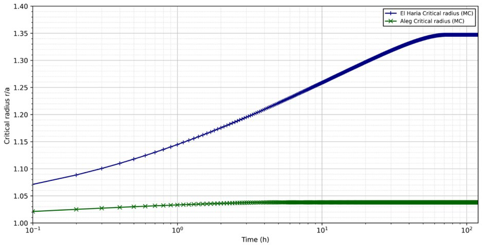
Wellbore instability in clay-rich intervals remains a major drilling challenge, even when the selected fluid density satisfies the conventional pressure window. This study evaluates delayed instability during exposure to a low-salinity water-based drilling fluid using outcrop-derived Aleg and El Haria materials as analogs for clay-rich Tunisian drilling intervals. Mineralogical, chemical, geotechnical, and shear strength data were integrated with a coupled stability analysis to link fluid exposure, pore pressure redistribution, effective stress modification, and hydration-induced strength degradation. The two materials exhibited contrasting hydro-mechanical behavior. El Haria is clay-rich, with 80% total clay mineral content, including 41% smectite and 47% illite/smectite mixed layers, and has a swelling pressure of 2112 kPa. Aleg is more carbonate-influenced, with 66% total clay mineral content, 28% calcite, and a lower swelling pressure of 576 kPa. Freshwater hydration strongly reduced the shear strength envelope; between approximately 15% and 45% water content, cohesion decreased by approximately 91% in Aleg and 70% in El Haria. The stability profiles show that El Haria reached rc/a = 1.10 after 0.3 h and the critical threshold of rc/a = 1.30 after 21.7 h, whereas Aleg remained close to rc/a = 1.03. This defines a practical temporal stability window for planning open-hole exposure during logging, casing, and cementing operations.

1. Introduction

Clay- and marl-rich intervals remain difficult to drill using water-based muds (WBMs). Their instability may start at the borehole wall and evolve into caving, washout, tight hole, hole fill, and stuck pipe [1]. Active shales are particularly problematic because water-based muds can trigger swelling, bit balling, wellbore closure, and strength loss [2]. These problems are not controlled by mud weight alone. They involve coupled mechanical and physicochemical processes, including hydraulic flow, osmosis, ion diffusion, pore pressure transmission, water content changes, and swelling pressure [3]. This coupling makes clay-rich formations sensitive to both fluid exposure and stress redistribution.
Fluid exposure alters the stability of clay-rich formations through coupled transport and weakening mechanisms. Water movement is driven not only by hydraulic overbalance but also by chemical potential gradients between the drilling fluid and shale pore fluid [4]. Salinity controls moisture adsorption or desorption and can modify shale pore pressure during fluid exposure [5]. In coupled models, chemical and thermal effects can also alter cohesion, stress redistribution, and critical mud weight with exposure time [6]. At the material scale, higher external water activity promotes swelling, microfracture development, and strength loss [7]. Therefore, WBM exposure must be treated as a time-dependent hydro-chemo-mechanical process rather than a simple mud weight condition.
El Haria and Aleg are relevant to this study because they represent clay- and marl-rich intervals, respectively, within a structurally complex Tunisian setting. In the El Kef–Tajerouine area, the Albian record marks the drowning of earlier carbonate platforms and a shift toward more open-marine marl and shale deposition [8]. This stratigraphic transition was non-uniform. Triassic salt bodies and Albian halokinetic movements locally controlled accommodation, thickness changes, and facies distribution [9]. Near-surface clayey materials associated with Aleg and El Haria have also been characterized using mineralogical, physicochemical, and geotechnical testing [10]. These points justify treating the studied materials as geological analogs for the clay-rich intervals encountered during drilling.
Current models can predict shale instability with increasing physical realism, ranging from elastic stress analysis to coupled chemo-thermo-poroelastic formulations. This progression is important because the predicted mud weight window becomes narrower when hydraulic, chemical, and thermal transport are included [11]. Coupled models also show that instability is time-dependent and may be initiated either at the borehole wall or inside the formation [12]. However, these modeling advances are rarely connected to the local laboratory characterization of clay-rich formations in Tunisia. Therefore, the gap is not only numerical. Although clay–fluid interactions have been widely investigated at the laboratory scale, their measured effects on hydration, swelling, and mechanical weakening are not always translated into drilling-oriented indicators that can support operational decisions, such as instability radius, time-dependent strength degradation, and drilling-fluid selection.
This gap requires a workflow that converts measured clay behavior into drilling stability indicators. Recent coupled models have shown that pore pressure, stress redistribution, collapse area, and mud weight limits are strongly affected by poroelastic, thermal, and chemical processes [13]. Sequential coupling also provides a practical route for linking the temperature, chemical activity, pore pressure evolution, and geomechanical response without losing the primary physical dependencies of the system [14]. In this study, the Stability Simulator was used within this logic to estimate the mud weight window, radial failure extent, and temporal stability window of the El Haria and Aleg clay-rich materials.
This study investigates near-surface clayey materials associated with the El Haria and Aleg formations and assesses their value as geological analogs for clay-rich intervals drilled using water-based muds. These materials were not treated as intact deep-core material. Instead, they represent surface-derived clayey formations whose behavior can provide first-order constraints on mineralogical sensitivity, water–clay interactions, and mechanical weakening. This study first characterizes the mineralogical, physicochemical, and geotechnical properties of these materials. These measured properties were then integrated into stability modeling using a custom-built stability simulator. The objective was to convert the material-scale behavior into drilling-oriented indicators, including the mud weight window, radial failure extent, and temporal stability window.

2. Geological and Drilling Context

2.1. Geological Context

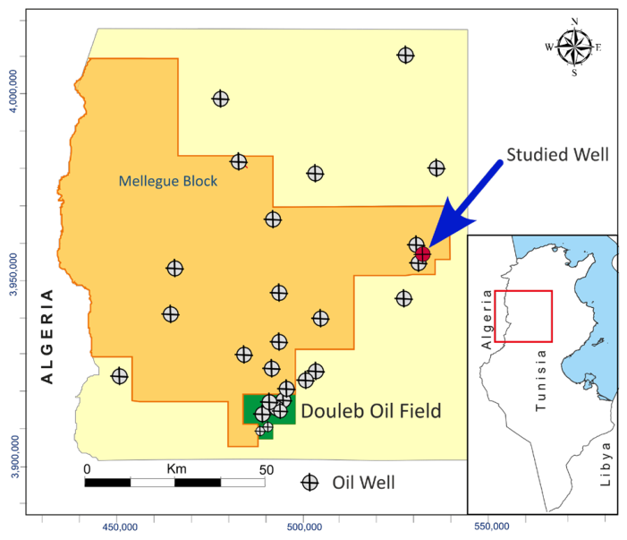
The study area is located in the Mellegue Block in northwestern Tunisia within an explored hydrocarbon province, where several wells have been reported. Figure 1 shows the geographic location of the study area and the positions of the investigated wells used in this study. In the Oued Bahloul Basin, the Aptian–Albian system is a documented exploration target, combining Aptian dolomitic reservoirs, Albian organic-rich shales, and structural traps [15]. The Serdj carbonate platform has direct petroleum significance because dolomitized platform units are associated with productive reservoir intervals in Tunisia [16]. At the Atlas scale, this prospectivity is controlled by strike-slip fault corridors, Triassic evaporites, and mixed structural–stratigraphic traps [17]. This setting justifies the consideration of overlying clay-rich formations as part of the drilling context.
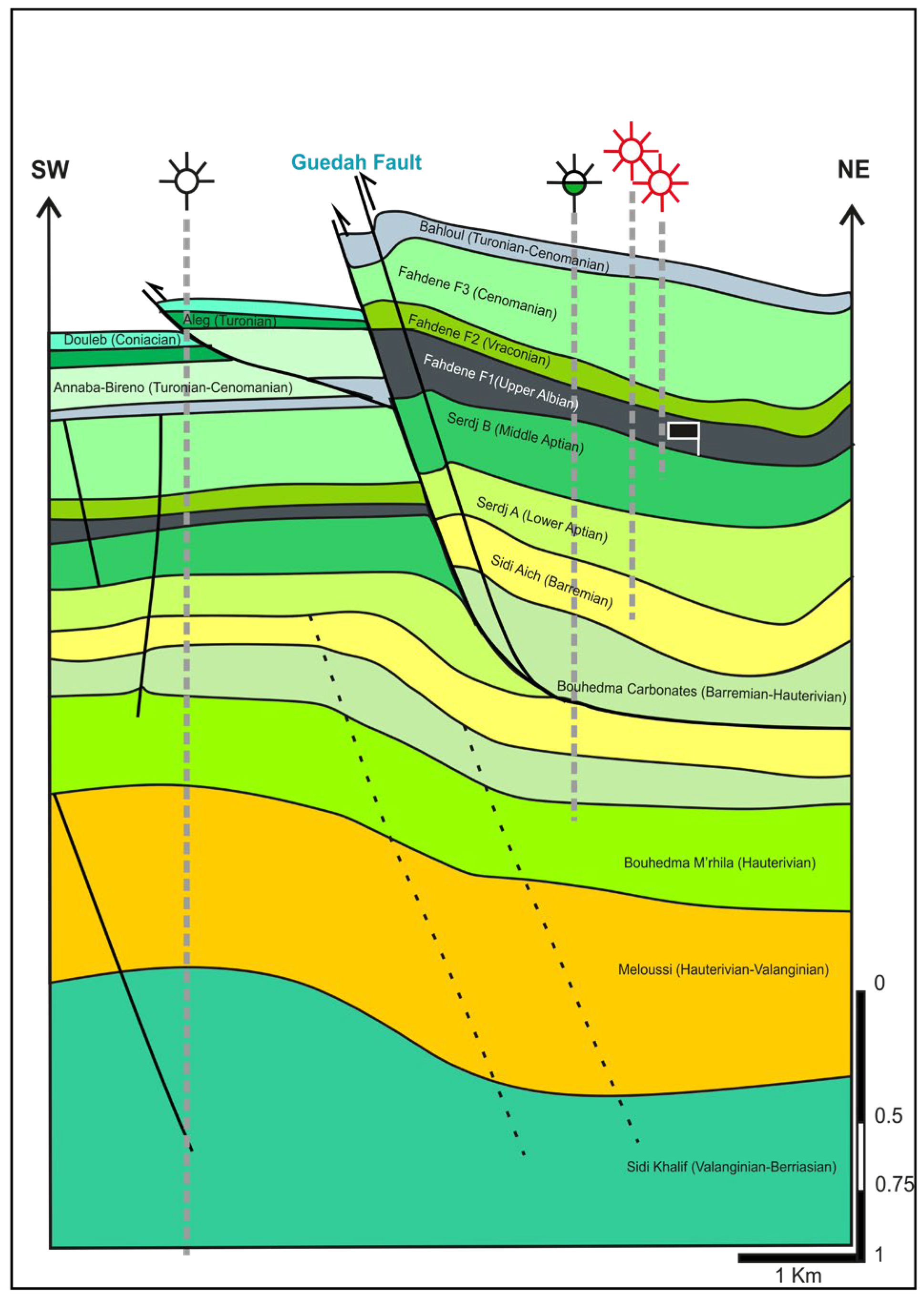
The Oued Bahloul (OBL) structure defines the structural frame of the drilled target rather than serving as a simple stratigraphic reference (Figure 2). The section places the Serdj interval beneath the Fahdene, Bahloul, Aleg, Abiod, and El Haria covers within a fault-bounded geometry. This architecture is consistent with the Early Cretaceous extensional pattern recognized near El Kef, where tilted blocks and half-grabens developed during the Pre-Aptian and Late Aptian–Albian stages [18]. In Oued Bahloul, seismic and well-log interpretation document fault-controlled Aptian–Albian depocenters, highs, and grabens [15]. Surface–subsurface correlations further connect the Serdj platform with the OBL wells and show synsedimentary control on the Lower Cretaceous thickness [16]. Regionally, Triassic bodies and halokinetic activity modified Albian accommodation and facies distribution in the El Kef–Tajerouine area [9]. This structural segmentation was followed by early Albian marly ramp deposition and the development of major discontinuities in the Tajerouine Sector [19].
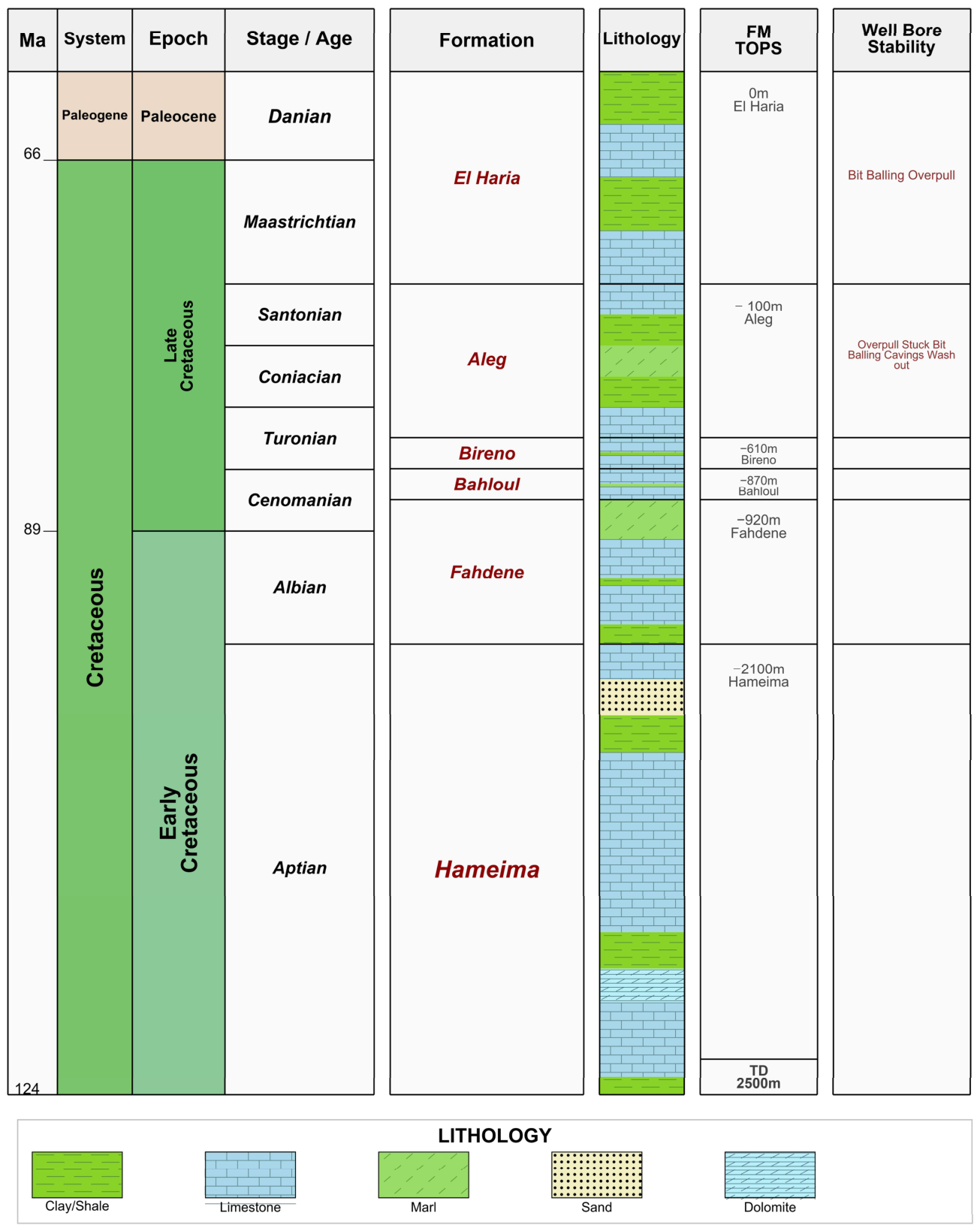
The stratigraphic log places the Serdj play as the main reservoir objective beneath a thick Cretaceous–Paleogene cover (Figure 3). In the Oued Bahloul area, the Aptian–Albian system includes dolomitized Serdj reservoir units and overlying organic-rich Albian intervals that contribute to source and sealing conditions [15]. Regional surface–subsurface correlations further connect the Serdj platform with productive subsurface units in the Oued Bahloul–Kasserine domain, where dolomitization improves reservoir quality [16]. Above the reservoir interval, the Hameima–Fahdene transition records the early Albian transgression in the Tajerouine area, from mixed carbonate–clastic shelf deposition to a thick marl- and shale-dominated succession [19,20]. Higher in the cover, the El Kef reference section records Abiod limestones overlain by the marly and clayey El Haria Formation [21]. In this framework, the Serdj interval defines the reservoir objective, whereas the overlying marl- and clay-rich units define part of the drilling envelope that must be managed through trajectory, pressure, mud weight, and fluid design decisions.
This study used outcrop-derived clayey samples associated with the Aleg and El Haria intervals rather than intact deep-core material [10]. This distinction is central to the geological setting. The stratigraphic log defines the position of these units within the cover above the Serdj reservoir objective (Figure 3), whereas the samples provide accessible analogs for evaluating mineralogical sensitivity and mechanical responses. At El Kef, the El Haria Formation belongs to the Upper Maastrichtian–Thanetian succession and consists mainly of marls and clays above the Abiod Limestone unit [21]. Earlier work on the Paleocene El Haria Formation at El Kef also described black shaly and marly deposits with thin limestone intercalations [22]. The sampled Aleg and El Haria materials were characterized using mineralogical, physicochemical, and geotechnical tests, including XRD, XRF, Atterberg limits, shear strength, triaxial, compressibility, and permeability measurements [10]. Therefore, they are used as formation analogs to constrain clay–water sensitivity and strength behavior before drilling-scale assessments.

2.2. Drilling Context

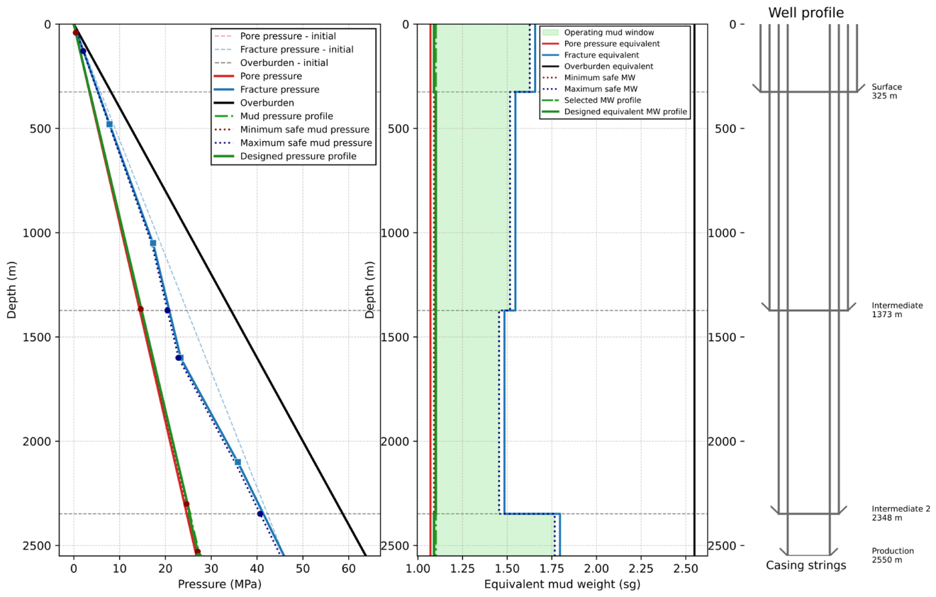
The conventional pressure window analysis showed that the selected mud weight profile remained within the safe operating window along the drilled sections (Figure 4). The equivalent mud weight was above the pore pressure limit and below the fracture pressure limit, whereas the casing program preserved the main pressure margin. This indicates that the well was not governed by an immediate static weight mud imbalance. However, this pressure-based assessment does not consider the time-dependent degradation of clay- and marl-rich intervals. Under water-based fluid exposure, water uptake, pore pressure redistribution, and strength loss may progressively reduce the stability margin, even when the initial mud weight remains within the conventional window.

3. Materials, Laboratory Testing and Modeling Workflow

3.1. Sampling Strategy and Studied Materials

Two clay-rich materials from the Aleg and El Haria intervals were selected as representative reactive formations for this study. Their selection was based on their stratigraphic position in the studied well and on the operational problems reported along the clay- and marl-rich drilled sections. The materials were collected from outcrop exposures rather than from deep cores. Therefore, they were treated as surface-derived formation analogs rather than direct equivalents of intact in situ core material.
The use of these analogs was supported by comparison with drill cuttings recovered from the corresponding subsurface intervals. X-ray diffraction analyses showed comparable mineralogical assemblages between the outcrop materials and the drilled cuttings. Methylene blue testing also indicated similar clay reactivity. Minor differences were observed in plasticity behavior, and a slight shift in the smectite reflection was noted in the cuttings. This shift was attributed to drilling mud contamination and sample disturbance during recovery. Therefore, the outcrop materials were preferred for the controlled hydration and mechanical testing program, whereas the cuttings were used mainly to verify formation consistency.
Fresh outcrop specimens were selected when the measured properties required preservation of natural fabric and mechanical continuity. These specimens were mainly used for shear-related and mechanical parameter tests. Representative prepared materials were used for index, physicochemical, and interaction-related tests when an intact structure was not required. This strategy allowed each parameter to be measured using the most suitable specimen type while keeping the interpretation linked to the same geological intervals. The resulting dataset therefore constrains the behavior of outcrop-derived analogs of the drilled formations, while acknowledging that fabric, stress history, and diagenetic state may differ from those of the deep subsurface interval.
All characterization data presented in this section were newly obtained from laboratory tests performed on the clay samples collected for this study and are therefore site-specific.

3.2. X-Ray Diffraction (XRD)

X-ray diffraction (XRD) analyses were performed to determine the mineralogical composition of the clays. The samples were first dried, ground, and homogenized and then analyzed as bulk powders and oriented clay mounts. The oriented preparations were examined under three conditions: air-dried, ethylene glycol-solvated, and heated at 550 °C to improve clay mineral identification. The measurements were conducted using a PANalytical powder diffractometer (Malvern Panalytical Ltd., Malvern, UK) with a Cu anode and Cu Kα radiation, operated at 40 kV and 40 mA. Phase identification and semi-quantitative assessment were carried out using HighScore Plus 2.0 software, following standard XRD interpretation procedures for clay minerals [23,24].

3.3. X-Ray Fluorescence Spectroscopy

X-ray fluorescence spectroscopy (XRF) was used to quantify the bulk chemical composition of the clay materials. This technique provides elemental data that complement the XRD results, particularly when mixed mineral phases make mineralogical interpretation less straightforward [25,26]. The analysis focused on the main oxides associated with Si, Al, Mg, Ca, Fe, Na, and K, and the results were reported as oxide weight percentages. Measurements were conducted under vacuum using a Bruker S8 Tiger wavelength-dispersive XRF spectrometer equipped with a 3 kW Rh anode tube (Bruker, Karlsruhe, Germany).

3.4. Geotechnical Tests

The geotechnical testing program was structured to connect the initial physical state of the clay materials with their identification properties and mechanical behaviors. The objective was to establish the baseline characteristics of the samples and assess their responses to compression, swelling, loading, and shear deformation. Therefore, the experimental program combined index tests, density-related measurements, and strength tests to interpret the behavior of the investigated clay-rich formations. Water content and bulk density were measured to define the initial conditions of the specimens and to follow the sample preparation and conditioning. The water content was determined according to ASTM D2216 [27], whereas the density and unit weight were evaluated following ASTM D7263 [28]. When required for phase relationship calculations, the specific gravity of the solids was obtained according to the ASTM D854 [29].
Atterberg limits were measured using the Casagrande cup method to determine the liquid limit, plastic limit, and plasticity index of each material, following ASTM D4318 [30]. One-dimensional oedometer tests were then used to quantify the compressibility and swelling behavior of the samples under controlled vertical loading. The consolidation parameters were interpreted according to ASTM D2435/D2435M [31], whereas the swelling response was evaluated following ASTM D4546 [32]. Direct shear tests were performed to define the shear failure envelope and derive the corresponding strength parameters according to ASTM D3080/D3080M [33]. Triaxial tests were used as complementary mechanical tests to determine the strength and deformation parameters under various drainage conditions. The testing framework followed ASTM D2850 [34] for unconsolidated undrained conditions, ASTM D4767 [35] for consolidated undrained testing with pore pressure measurement, and ASTM D7181 [36] for consolidated drained testing. Permeability was evaluated using an oedometer cell and filter-press tests, following the procedure adopted by Hamdi [37,38].

3.5. Stability Modeling Workflow

The stability analysis followed the coupled chemo-poro-thermoelastic framework of Ghassemi et al. for swelling shale around a wellbore. This formulation extends linear chemo-poroelastic shale theory by coupling pore pressure diffusion, solute transport, chemical osmosis, thermal diffusion, thermal-osmotic effects, and stress redistribution [39,40]. In this study, the framework was implemented as the numerical basis for the stability simulator. The model was used to compute the time-dependent evolution of pore pressure, solute concentration, temperature, and effective stresses around the borehole before converting these fields into drilling-oriented stability indicators.

3.5.1. Chemo-Poro-Thermoelastic Stability Model

The numerical simulator was formulated using the coupled chemo-poro-thermoelastic wellbore model proposed by Ghassemi et al. (2009) [40]. This framework describes the time-dependent redistribution of temperature, pore pressure, solute mass fraction, and stress around a borehole drilled through swelling shales. It extends the linear chemo-poroelastic theory of Ghassemi and Diek (2003) [39], in which solute transfer, chemical osmosis, pore pressure diffusion, and deformation are coupled within the poroelastic description of shale–fluid interactions. The formulation also follows the thermodynamic basis of Heidug and Wong (1996) [41], in which chemical potential gradients are linked to fluid transport and stress evolution in chemically active, porous media. The model starts from the infinitesimal strain tensor, defined as
ε i j = 1 2 u i x j + u j x i
where εij denotes the strain tensor, ui the displacement component, and xi the spatial coordinate. The constitutive formulation then expresses the total stress as a function of elastic deformation, pore pressure, solute mass fraction, and temperature. In the framework of Ghassemi et al. (2009) [40], two coupled relations are retained: the stress–strain relation (2), which governs the mechanical response of the shale, and the pore volume or fluid content relation (3), which describes the storage response of the porous medium under hydraulic, chemical, and thermal perturbations.
σ ˙ i j = 2 G   ε ˙ i j + K 2 G 3 ε ˙ k k δ i j α   p ˙   δ i j + χ   C ˙ s   δ i j γ 1   T ˙   δ i j
ζ ˙ = α   ε ˙ k k + β   p ˙ + χ   C ˙ s γ 2   T ˙
where σij denotes the total stress tensor, G the shear modulus, K the bulk modulus, and δij the Kronecker delta. The coupled variables are pore pressure p, solute mass fraction Cs, and temperature T. The coefficients α′, χ, and γ1 represent the poroelastic, chemo-mechanical, and thermal contributions to the stress response in the formulation of Ghassemi et al. (2009) [40], respectively. In the fluid content relation, ζ represents the variation in fluid content or pore volume fraction. The parameters α, β′, χ′, and γ2 define the coupling with volumetric strain, hydraulic, chemical, and thermal storage, respectively.
The governing equations of the model were obtained by combining the constitutive relations in Equations (2) and (3), the transport laws in Equations (4)–(6), and the balance equations for momentum, fluid mass, solute mass, and energy. This procedure leads to four coupled field equations: mechanical equilibrium, pore pressure diffusion, solute diffusion, and thermal diffusion equations. These equations describe the time-dependent evolution of the displacement, pore pressure, solute mass fraction, and temperature around the wellbore.
J f = ρ f k p R   ρ f R T 0 M s C s C d C s + ρ f K T T
J s = ρ f D s C s ρ f D T T
J q = k T T
The coupled field equations were obtained by substituting the constitutive relations in Equations (2) and (3) and the transport laws in Equations (4)–(6) into the balance equations of momentum, fluid mass, solute mass, and energy, following the formulation of Ghassemi et al. (2009) [40]. They were implemented in the Stability Simulator to compute the time-dependent distributions of pore pressure, solute mass fraction, temperature, and stress around the borehole.

3.5.2. Mohr–Coulomb-Based Stability Index

The transient pore pressure and stress fields obtained from the coupled chemo-poro-thermoelastic model were converted into stability indicators using the Mohr–Coulomb shear failure criterion. This criterion was selected because it directly uses the cohesion and friction angles measured from laboratory shear testing and provides a conservative estimate of shear failure in the effective-stress domain. At each radial position and exposure time, the computed effective principal stresses were projected onto the Mohr–Coulomb envelope. Failure is approached when the Mohr circle becomes tangent to the envelope, whereas stress states that remain below the envelope are considered stable [42]. Only the Mohr–Coulomb criterion was retained in this study to maintain consistency between the experimental strength parameters and the numerical stability assessment.
The failure index is defined as
F I M C = c + σ n t a n φ τ
This can be equivalently written as
F I M C = L M C τ
where LMC is the Mohr–Coulomb shear limit, and τ′ is the mobilized shear stress.
L M C = σ m s i n φ + c c o s φ
where σ′m is the mean effective stress, cis the cohesion, and φ′ is the friction angle.
τ = σ θ θ σ r r 2
Thus, FIMC > 0 indicates stable conditions, FIMC < 0 indicates instability, and FIMC = 0 corresponds to the failure limit of the system.

3.5.3. Simulator Method

The two-dimensional finite element formulation was executed within a conforming annular domain extending from the borehole radius to the external formation boundary. Spatial discretization was achieved using linear triangular P1 elements derived from a polar-type annular mesh, which maintained the circular geometry of the wellbore and offered a more accurate representation than a truncated Cartesian grid. This approach is particularly crucial for resolving steep gradients and stress concentrations near the borehole wall. Python version 3.14.0. was chosen because of its flexibility, scientific libraries, and rapid integration with a custom graphical user interface.

4. Results

The results are organized from outcrop-derived material properties to drilling-oriented stability responses. Mineralogical and chemical contrasts were first used to define the clay sensitivity of the Aleg and El Haria analogs. The geotechnical and strength parameters were then linked to the coupled pore pressure and effective stress evolution before deriving the Mohr–Coulomb stability index.

4.1. Mineralogical and Chemical Properties

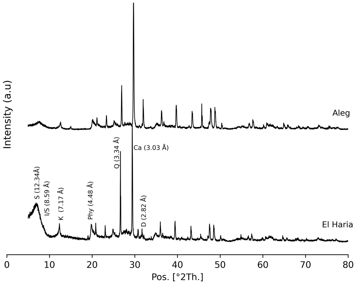
The XRD patterns show a clear mineralogical contrast between El Haria and Aleg (Figure 5). El Haria is characterized by a clay-rich assemblage with smectitic and mixed-layer components associated with kaolinite and minor carbonate. Aleg shows a more carbonate-influenced signature, with a marked calcite contribution and clay minerals represented mainly by smectite and kaolinite. This distinction suggests two different material behaviors: a more clay-sensitive El Haria facies and a clay–carbonate Aleg facies, with potential implications for water affinity, plasticity, and mechanical weakening.
The semi-quantitative XRD results confirmed a clear compositional contrast between Aleg and El Haria (Table 1). El Haria had a higher total clay mineral content, with a TCCM of 80%, compared to 66% for Aleg. Therefore, the non-clay fraction was larger in Aleg, mainly because of its higher calcite content (28%) relative to that of El Haria (17%), whereas dolomite remained low and similar in both materials (2%). Quartz was also a minor component but slightly higher in Aleg (4%) than in El Haria (1%). The clay fraction exhibited a second level of contrast. Aleg contained 48% smectite, 45% kaolinite, and 7% illite/smectite mixed layers, indicating a smectite–kaolinite clay assemblage diluted by carbonates. El Haria contained 41% smectite, only 12% kaolinite, and a much higher proportion of illite/smectite mixed layers (47%). These data show that El Haria is more clay-rich, whereas Aleg is more carbonate-rich. Therefore, the difference is not limited to the total clay content; it also reflects distinct clay assemblages that may lead to different water affinities, plasticities, and mechanical-weakening pathways.
The XRF data reinforce the mineralogical contrast between Aleg and El Haria (Table 2). El Haria was enriched in SiO2 and Al2O3, reaching 48.66% and 14.69%, respectively, compared to 32.57% and 13.23% in Aleg, respectively. This composition indicates a stronger contribution from silicate and aluminosilicate minerals. Its higher K2O content, 1.32% against 0.50% in Aleg, also agrees with the presence of illitic and mixed-layer clay components identified by X-ray diffraction (XRD) analysis. In contrast, Aleg is marked by a higher CaO content (18.33% compared with 9.55% in El Haria), reflecting a stronger carbonate contribution, mainly from calcite. Fe2O3 remained nearly identical in both materials, with 5.19% in Aleg and 5.12% in El Haria, while the LOI was also comparable at 15.93% and 15.40%, respectively. These geochemical data separate the silicate-rich, clay-dominated El Haria material from the carbonate-influenced Aleg clay assemblage.

4.2. Geotechnical and Mechanical Properties

4.2.1. Geotechnical Index and Swelling Properties

The geotechnical properties of El Haria and Aleg showed a clear contrast (Table 3). El Haria displayed higher plasticity, with a liquid limit of 96.4%, a plastic limit of 36.9%, and a plasticity index of 59.51%, compared with 52%, 26%, and 26.05% for Aleg, respectively. The methylene blue capacity was also slightly higher in El Haria (30 meq/100 g) than in Aleg (26 meq/100 g), indicating greater clay activity. This difference was more pronounced in the swelling response. El Haria reached a swelling index of 0.13 and a swelling pressure of 2112 kPa, whereas Aleg recorded lower values of 0.083 and 576 kPa, respectively. These results indicate that El Haria is a more plastic and swelling-sensitive material, whereas Aleg exhibits a more moderate hydro-mechanical response.

4.2.2. Water-Induced Degradation of Mohr–Coulomb Strength Parameters

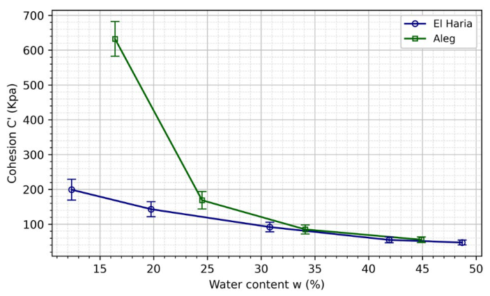
The Mohr–Coulomb parameters were derived from consolidated-drained direct shear tests performed after conditioning the specimens at different water contents under freshwater hydration (Figure 6). This protocol was used to reproduce the mechanical effect of water uptake during exposure to water-based fluids, where hydraulic invasion, chemical imbalance, and diffusive transport increase the water content of clay-rich formations. Both materials exhibited a significant loss of shear strength as hydration progressed; however, their degradation paths differed. In Aleg, the cohesion dropped sharply from approximately 630 kPa at 16% water content to 170 kPa at 25%, then decreased to nearly 85 kPa at 34% and 55 kPa at 45%. El Haria showed a more progressive reduction, from approximately 200 kPa at 13% to 145 kPa at 20%, 95 kPa at 31%, and nearly 50–60 kPa above 42%.
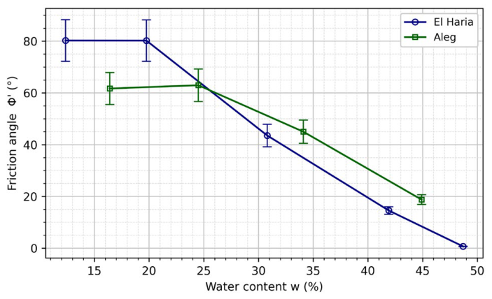
The friction angle followed the same trend during freshwater-induced weakening (Figure 7). El Haria decreased from approximately 80° at low water content to 44° at 31%, 15° at 42%, and almost 0° at approximately 49%. Aleg decreased from about 62–63° at 16–25% to 45° at 34% and 18° at 45%. These results show that freshwater hydration contracts the Mohr–Coulomb envelope by reducing both cohesion and frictional resistance, providing a direct mechanical pathway from clay–water interactions to borehole instability.
The high cohesion and friction angle measured at low water content were interpreted as peak apparent shear-strength parameters, mainly controlled by the structured and cemented fabric of the clay-rich formations. The XRD and XRF results indicate a carbonate contribution, particularly in Aleg, with 28% calcite, and also in El Haria, with 17% calcite. Such carbonate cementation and preserved interparticle bonding can increase the initial peak shear resistance and produce a steep apparent Mohr–Coulomb envelope at low water content, especially before hydration-induced bond degradation.
As the water content increases, the clay–carbonate contacts and cemented bonds progressively weaken, causing the apparent strength envelope to contract. This mechanism explains the sharp decrease in apparent cohesion and the strong reduction in apparent friction angle observed during hydration. Because full saturation was not explicitly confirmed prior to testing, a minor contribution from unsaturated effects, such as matric suction and capillary bonding, cannot be completely excluded; however, these effects are considered a possible secondary contribution for the high initial strength.

4.3. Time-Dependent Stability Evolution of El Haria

This section examines the time-dependent stability response of El Haria during exposure to the low-salinity water-based mud used in the 26-inch hole section. The simulated El Haria depth of 100 m corresponds to the 26-inch surface hole section, which extends from the surface to the surface casing shoe at 325 m. The analysis followed the causal sequence from pore pressure perturbation to effective stress redistribution and Mohr–Coulomb stability loss to quantify the progressive reduction in the near-wellbore stability margin.

4.3.1. Initial Mohr–Coulomb Stability State

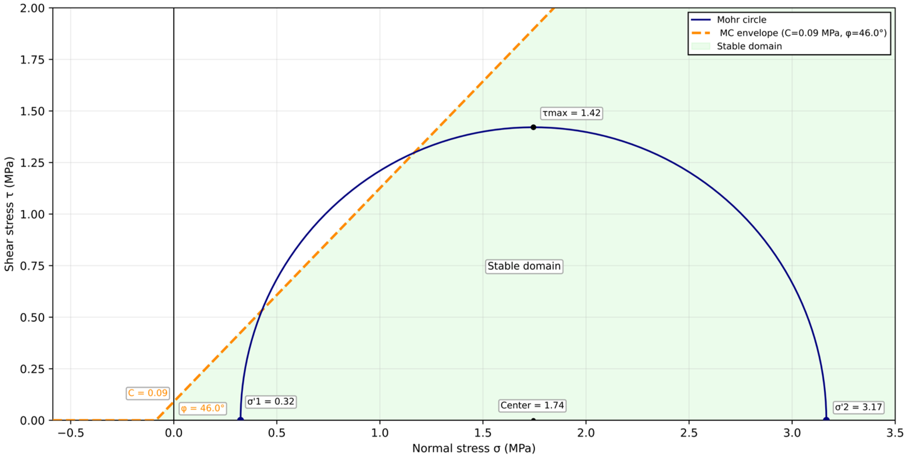
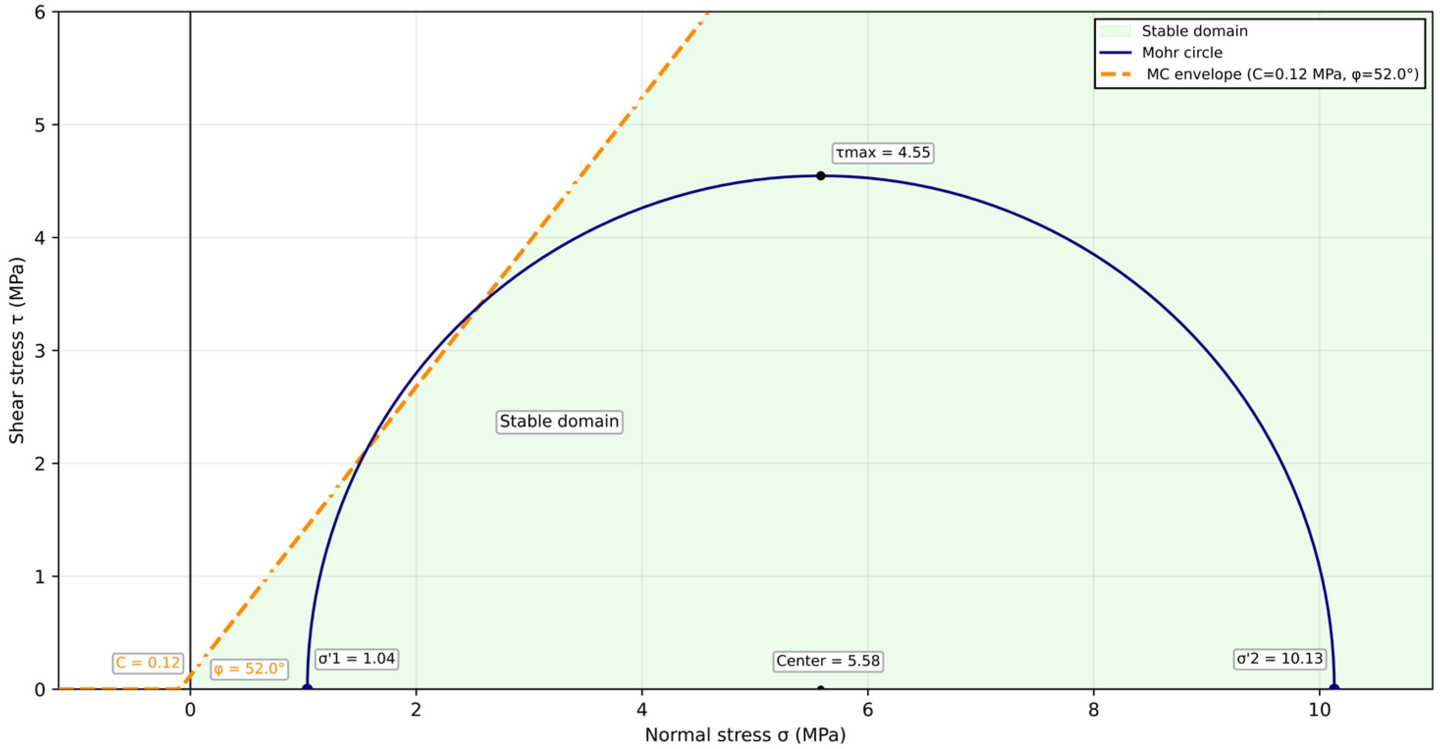
The Mohr–Coulomb stability profiles (Figure 8) were evaluated using the pressure and stress inputs listed in Appendix A, Table A1. The mud pressure and pore pressure were estimated from the mud weight and pore pressure gradients defined in the pre-drill geomechanical assessment, whereas the far-field stresses were assigned from the adopted depth-dependent stress conditions at the studied intervals. These inputs defined the initial effective stress state before low-salinity WBM exposure. The shear strength envelope was defined using cohesion values of 0.09 MPa for El Haria and 0.12 MPa for Aleg, with friction angles of 46° and 52°, respectively. At each radial position and exposure time, the mobilized shear stress was compared with the Mohr–Coulomb resistance. Stable zones correspond to stress states below the failure envelope, whereas unstable zones correspond to intervals in which the mobilized shear stress exceeds the available resistance.

4.3.2. Coupled Pore Pressure, Effective-Stress and Stability Response

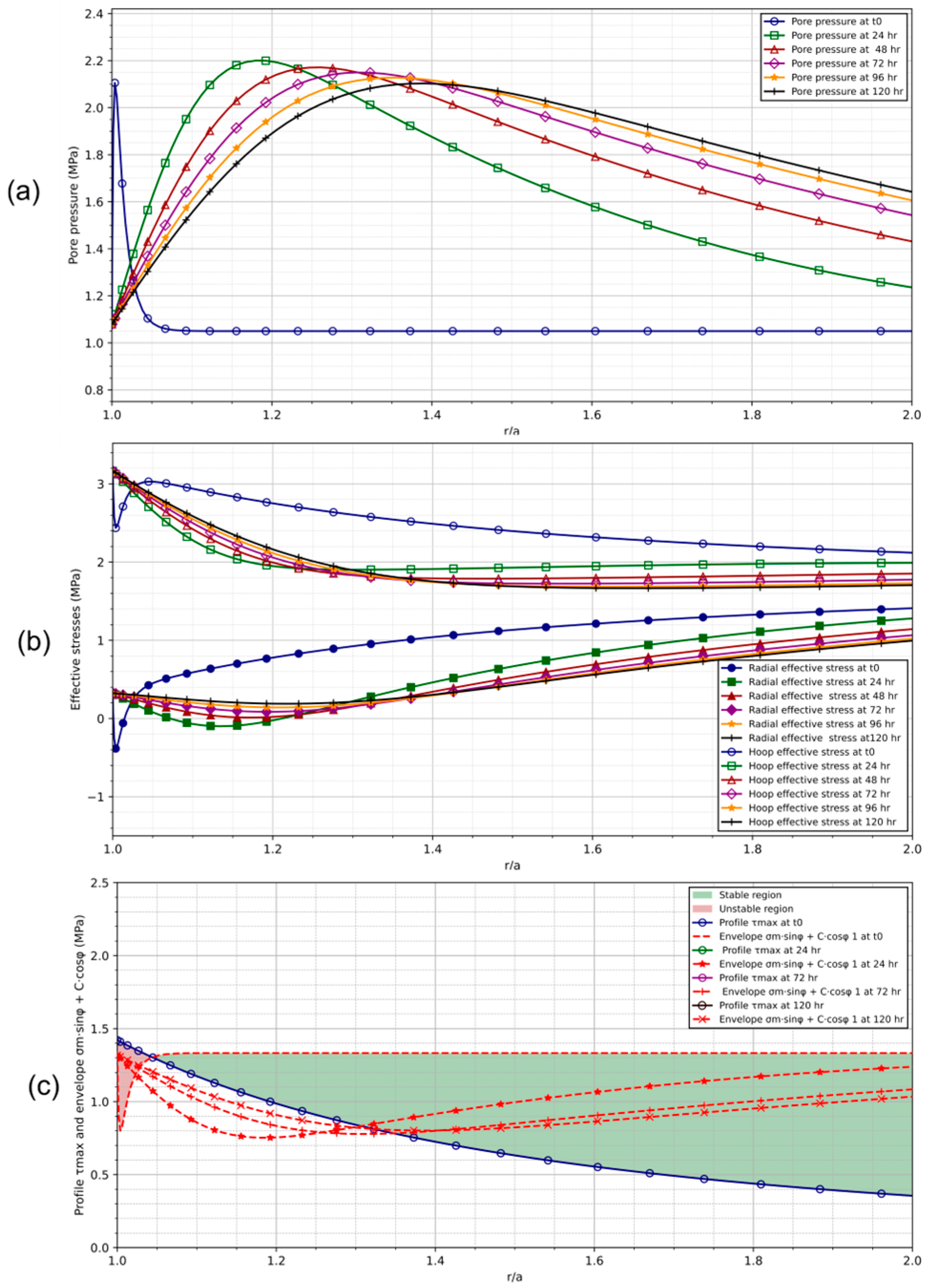
Under low-salinity WBM exposure in the 26-inch section, El Haria exhibited a clear time-dependent stability response (Figure 9). The input parameters used for the coupled stability analysis are listed in Table A1 in Appendix A. Mud pressure and pore pressure were estimated from the pressure gradient framework of the pre-drill geomechanical assessment, whereas far-field stresses and strength parameters were assigned to the studied depth interval.
The pore pressure profile rapidly deviated from the initial condition near the borehole wall (Figure 9a). With increasing exposure time, the perturbation migrated outward and developed a pressure peak within the near-wellbore zone. This indicates that fluid–formation interaction is not a wall-bound process but progressively modifies the pressure field over a finite radial distance.
This pressure redistribution directly affected the effective stress state (Figure 9b). The radial and hoop effective stresses changed mainly within the disturbed zone, where the pore pressure gradient was highest. Consequently, the local shear margin decreased, and the stress state moved closer to the Mohr–Coulomb limit than before.
The stability profile captured this transition (Figure 9c). The initially stable condition evolved into an unstable interval that was adjacent to the borehole wall. This interval expanded outward over time, whereas the external part of the formation remained stable. Thus, El Haria instability cannot be explained by the initial mud pressure alone. It develops through a time-dependent sequence controlled by low-salinity WBM exposure, pore pressure redistribution, effective stress modification, and progressive loss of Mohr–Coulomb stability.

4.4. Time-Dependent Stability Evolution of Aleg

The simulated Aleg depth of 320 m corresponds to the 26-inch surface hole section, which extends from the surface to the surface casing shoe at 325 m. The initial Mohr–Coulomb state was computed using the field stress, pore pressure, and mud-pressure inputs reported in Appendix A, Table A1. The reference condition corresponds to the hydrostatic pressure state adopted for the low-salinity WBM interval. The calculated Mohr circle remained below the Mohr–Coulomb failure envelope (Figure 10). This indicates that Aleg was mechanically stable under the initial conditions and was not critically stressed before exposure to the fluid. Therefore, the following analysis focuses on the time-dependent response induced by WBM interaction, including pore pressure redistribution, effective stress modification, and progressive reduction in the stability margin.
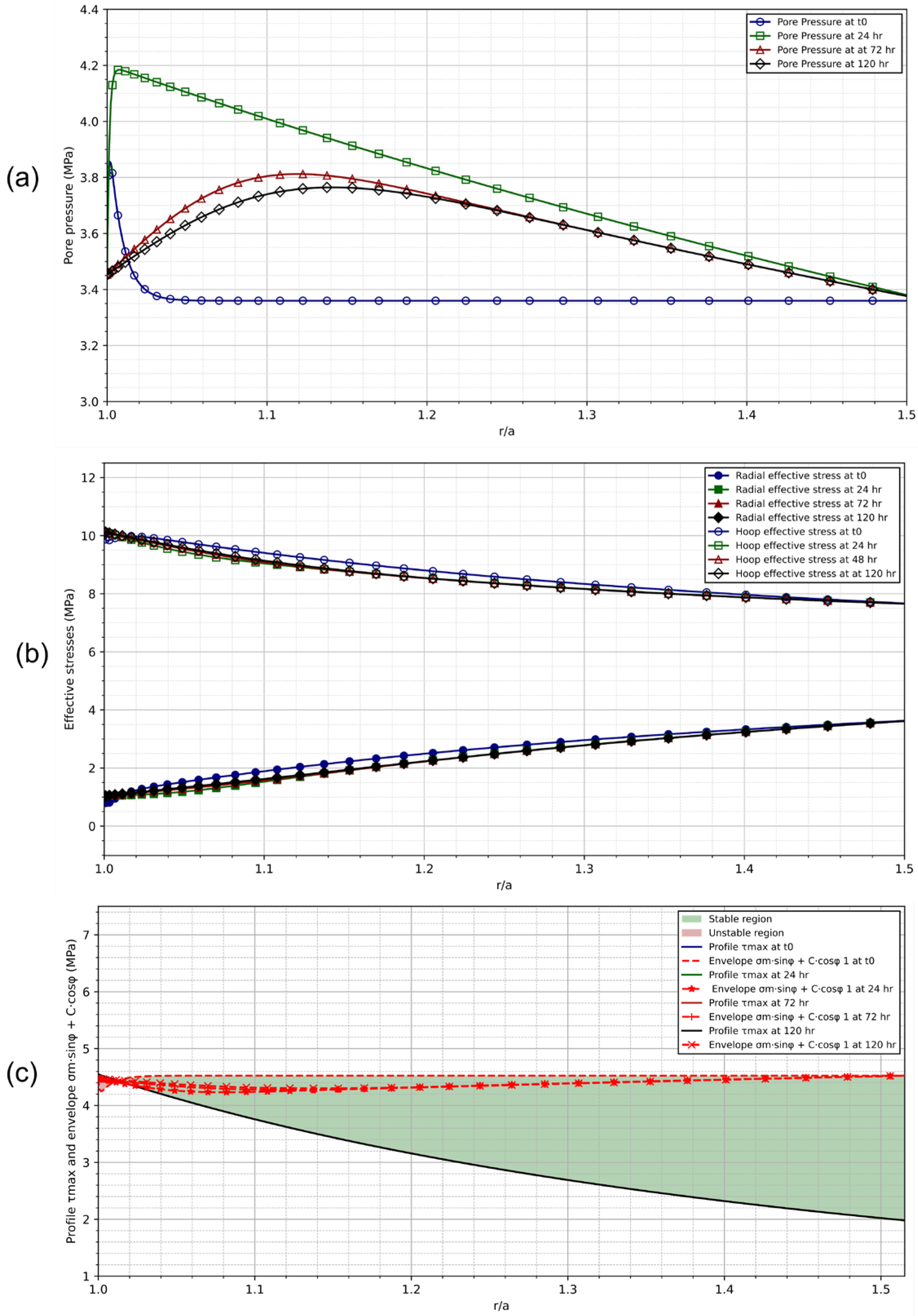
Aleg started from a stable mechanical state; however, the opening of the borehole and exposure to low-salinity WBM disturbed the near-wellbore pressure field (Figure 11a–c). The pore pressure response was time-dependent (Figure 11a). The strongest perturbation occurred after 24 h, with a near-wellbore pressure peak of approximately 4.2 MPa. Subsequently, the peak decreased to approximately 3.7–3.8 MPa and shifted slightly from the borehole wall. This indicates that the mud–formation interaction modified the pressure field, but the perturbation remained radially limited.
The effective stress profiles showed moderate redistribution (Figure 11b). The radial effective stress increased gradually with distance from the borehole, whereas the hoop effective stress decreased. The curves at different exposure times remained close to each other, indicating that the pressure perturbation did not generate strong mechanical destabilization in Aleg.
The Mohr–Coulomb stability profile confirmed this behavior (Figure 11c). The stress profile remained below the failure envelope over the analyzed radial intervals. Therefore, Aleg remained within a stable domain despite low-salinity WBM exposures. This result suggests that under the adopted conditions, the coupled pressure and stress changes were insufficient to trigger significant radial instability. Therefore, the formation response was controlled by a limited pressure perturbation and a weak reduction in the stability margin rather than by progressive borehole failure.

4.5. Critical Radius and Temporal Window

The critical radius profile separates the two formations into two distinct stability behaviors (Figure 12). For El Haria, rc/a reached 1.10 after 0.3 h, marking the limit of acceptable near-wellbore degradation. The unstable zone continued to propagate outward, reaching 1.20 after 3.4 h. The critical threshold of 1.30 was reached after 21.7 h, indicating a transition from limited wall damage to an operationally significant instability. Therefore, El Haria exhibited a clear time-dependent loss of stability under low-salinity WBM exposure.
Aleg showed a significantly weaker response. Its critical radius remained close to 1.03 during the analyzed exposure time. This radial extension was negligible and could be considered within the stable near-wall range. Unlike El Haria, Aleg did not exhibit significant time-dependent propagation of instability. Therefore, the comparison identified El Haria as a time-sensitive formation, whereas Aleg remained mechanically stable under the same low-salinity WBM exposure conditions.

5. Discussion

A conventional mud weight window is necessary but insufficient for evaluating clay-rich formations exposed to water-based mud. It defines the initial pressure balance between the pore and fracture pressures. However, it does not describe how the near-wellbore material evolves after fluid contact. This distinction is critical because instability in clay-rich formations is not only a mechanical stress problem. Zhang emphasized that mechanical analysis alone is inadequate when drilling fluid chemistry, water activity, membrane efficiency, and clay content control the near-wellbore response [43]. Ghassemi also showed that mud chemistry, hydraulic gradients, and thermal effects can modify pore pressure and stress distributions around the borehole. In the present study, both El Haria and Aleg were initially stable in the Mohr–Coulomb domain. Therefore, their later divergence reflects exposure-driven evolution rather than an immediate mud weight imbalance.
Therefore, the operational question is not whether the mud weight is initially safe. Rather, it indicates the duration for which the open hole can remain exposed before the pressure–stress–strength system becomes critical. This is the main added value of the present study. Under the same low-salinity WBM exposure, El Haria evolved toward delayed instability, whereas Aleg remained close to its initial stable condition. This contrast must be explained by formation sensitivity and not by the pressure window alone.
The mineralogical contrast provides the first explanation. The present mineralogical data identify El Haria as the clay-richest material, with TCCM = 80%, including 41% smectite and 47% illite/smectite mixed layers. This agrees with Benaoun et al., who reported a comparable clay-dominated signature for El Haria and a more carbonate-influenced character for Aleg than for El Haria [10]. Aleg has a lower total clay mineral content, with TCCM = 66%, and a stronger carbonate contribution, with 28% calcite. This difference indicates that water sensitivity cannot be ranked solely based on the smectite content. It depends on the full clay assemblage, carbonate fraction, and continuity of the clay network.
The geotechnical response confirmed this separation effect. El Haria had a PI of 59.5% and a swelling pressure of 2112 kPa, whereas Aleg had a PI of 26% and 576 kPa. This trend is consistent with that of Benaoun et al., who reported more plastic and swelling-sensitive behavior for El Haria than for Aleg [10]. These values indicate that El Haria has a higher capacity to absorb water, deform, and generate internal swelling stresses under constrained hydration. Zhang et al. supported this mechanism by showing that clay-rich and montmorillonite-bearing shales have stronger water affinity, higher swelling tendency, more microfracture development, and lower strength during water exposure [7].
The near-surface expression of El Haria may further amplify this effect. Shallow clay-rich materials can preserve surface overprints expressed by weathering, superficial reworking, fabric opening, and repeated wetting–drying effects. These processes do not replace primary mineralogical controls. However, they can increase hydraulic accessibility and reduce mechanical continuity. Zorgati et al. showed that, in northwestern Tunisia, weathered clay-rich materials lose cohesion when the clay fraction and water content increase [44]. Hadji et al. also showed that shrink–swell susceptibility in clay and marl formations is controlled by lithology, swelling minerals, plasticity, methylene blue value, and moisture variation [45]. These regional studies support the interpretation that the El Haria response is not only mineralogical but may also be reinforced by its shallow and water-accessible fabric.
Aleg behaves differently because its carbonate-influenced framework buffers hydration damage. Carbonate does not suppress clay reactivity. However, it can interrupt the clay network continuity and reduce the transfer of mineral sensitivity to borehole-scale instability. This explains why Aleg remains less time-sensitive under the same low-salinity WBM exposure. El Haria combines high clay content, mixed-layer clays, high plasticity, high swelling pressure, and a more water-accessible fabric. Aleg remains reactive, but its carbonate-bearing structure limits the radial expression of this instability.
Freshwater hydration provides a mechanical link between fluid exposure and strength loss. In the present study, increasing water content strongly reduced the Mohr–Coulomb resistance of both materials through different degradation pathways. Aleg exhibited the sharpest collapse in its cohesion. Between approximately 15% and 45% water content, cohesion decreased by nearly 91%, indicating a rapid loss of bonding and cementation effects during hydration. El Haria also weakened significantly, with an estimated cohesion loss of approximately 70% over the same hydration range. Its degradation was less abrupt but more critical because it occurs in a material already characterized by high plasticity, high swelling pressure, and stronger clay continuity. The friction angle followed a similar weakening direction. Therefore, hydration not only reduces apparent cohesion. It also degrades particle contacts, fabric resistance, and shear transfer. The Mohr–Coulomb envelope contracts as water content increases over time. This mechanism explains why an initially stable stress state can become vulnerable during low-salinity WBM exposure. Zhang et al. support this interpretation by linking water exposure to swelling, microfracture development, and strength reduction [7]. Tian et al. further confirmed that hydration markedly reduces shale strength, while inhibition can preserve mechanical integrity [46].
The stability profiles show the stress-side expression for the same process. In El Haria, low-salinity WBM exposure generated a clear pore pressure perturbation in the near-wellbore zone. Ghassemi and Diek established the chemo-poroelastic basis for this behavior by linking solute transfer, chemical osmosis, pore pressure diffusion, and stress redistribution in swelling shales [39]. In the present case, the pressure perturbation changed the radial and hoop effective stresses and progressively reduced the local shear margin. Therefore, instability appears to be a delayed phenomenon. It starts from a stable Mohr–Coulomb state and evolves as exposure modifies the pressure field and effective stress distribution.
Aleg showed the same physical coupling but with a weaker expression. The pore pressure disturbance remained limited, and the effective stress redistribution did not generate significant outward propagation of the instability. This agrees with Ghassemi et al. (2009) [40], where the magnitude of the pore pressure and stress response depends on the material and fluid parameters. In Aleg, the carbonate-influenced framework appears to buffer the transfer from fluid exposure to radial instability. Therefore, the critical radius remains below the acceptable rc/a = 1.10 limit.
The practical implication is that mud weight should be treated as a necessary pressure parameter rather than as a complete stability solution for the wellbore. In El Haria, the main operational risk is the exposure time. The critical radius evolution defines a temporal stability window, which is one of the main contributions of this study. The response remained within the acceptable near-wall degradation limit until rc/a = 1.10, which was reached after 0.3 h. Instability then propagated progressively and became operationally critical when rc/a = 1.30, reached after 21.7 h. This time window identifies the interval during which drilling, logging, or casing operations should be completed before the predicted washout becomes critical. Aleg does not exhibit the same behavior because its critical radius remains below rc/a = 1.10.
Van Oort (2003) framed this operational problem by showing that shale stabilization depends on controlling transport processes and the physical and chemical changes induced by water-based muds [3]. The present results also support selective inhibition. El Haria-type materials require stronger inhibition because their response is governed by clay continuity, swelling pressure, and water-accessible fabric. Zhang et al. showed that low-water-activity working fluids can reduce hydration damage and help maintain formation stability, especially in water-sensitive shales [7]. Tian et al. further showed that inhibitive water-based systems can reduce clay hydration and preserve shale strength [46]. Therefore, the drilling-fluid program should be adapted to the time sensitivity of each clay-rich interval, as well as to the expected pressure window.
Two limitations should be considered when interpreting the stability profiles. First, the coupled calculation updates pore pressure and effective stresses with exposure time, but it does not dynamically update cohesion and friction angle during hydration. Therefore, the computed profiles describe the stress-side response, whereas direct shear tests provide evidence of strength-side degradation. A fully predictive workflow would require water-content-dependent strength parameters. The second limitation concerns the fixed-radius assumption. The present workflow calculates pore pressure redistribution, effective stresses, and stability profiles around the initial borehole radius. It does not update borehole geometry after shear failure or washout. In reality, spalling and cavings may expose fresh, previously uninvaded material to the drilling fluid, changing both the hydraulic/chemical boundary conditions and the stress redistribution around the enlarged hole. This feedback could modify the estimated temporal stability window. A fully predictive framework would require iterative coupling between failure, radius enlargement, renewed fluid exposure, transport recalculation, and updated Mohr–Coulomb stability. This extension is identified as a key perspective of the present work.

6. Conclusions

This study shows that an initially acceptable mud weight window does not ensure time-independent stability in clay-rich formations exposed to low-salinity water-based mud. The key mechanism is delayed instability, which develops through mud–formation interactions, pore pressure redistribution, effective stress modification, and a progressive reduction in shear resistance. The main contribution of this study is to show that a well can remain within the conventional mud weight window while developing delayed instability through exposure-driven stress and strength evolution.
El Haria and Aleg follow different hydro-mechanical pathways. El Haria has a higher clay mineral content, with TCCM = 80%, including 41% smectite and 47% illite/smectite mixed layers. It also exhibited high plasticity, with a PI of 59.51% and a high swelling pressure of 2112 kPa. Its response may be amplified by a near-surface overprint that increases fabric disturbance and water accessibility. Aleg has a lower total clay content (TCCM = 66%) and a more carbonate-influenced framework, with 28% calcite, PI = 26.05%, and a lower swelling pressure of 576 kPa.
Freshwater hydration contracts the Mohr–Coulomb strength envelope of the rock mass. Between approximately 15% and 45% water content, the cohesion decreased by approximately 91% in Aleg and 70% in El Haria. The friction angle also decreased significantly with hydration, indicating that water exposure weakened both bonding and frictional resistance. This strength degradation acted in conjunction with pore pressure redistribution and effective stress modification around the borehole.
The stability profiles synthesize this coupled response. They demonstrate how pore pressure perturbation and stress redistribution evolve into radial stability loss. Expressed as the critical radius or normalized washout, El Haria reached rc/a = 1.10 after 0.3 h and rc/a = 1.20 after 3.4 h, and reached the critical threshold of rc/a = 1.30 after 21.7 h. This defines a practical time window in which drilling operations remain acceptable before instability becomes critical. Aleg remained close to rc/a = 1.03, below the acceptable limit of rc/a = 1.10, indicating negligible radial degradation.
The practical implication is that mud weight remains necessary but is insufficient for clay-rich intervals. For El Haria-type formations, exposure time and inhibition strategy must be treated as drilling design parameters. This study remains a formation-analog assessment. Future studies should couple water-content-dependent strength degradation with borehole-radius updating after failure to improve the prediction of progressive washout.

Author Contributions

Conceptualization, M.A. and N.H.; methodology, M.A., I.B. and N.H.; investigation, M.A. and M.K.; data curation, M.A., M.K. and I.B.; formal analysis, M.A.; software, M.A.; validation, M.K., I.B., R.A. and N.H.; visualization, M.A.; writing—original draft preparation, M.A.; writing—review and editing, M.K., I.B., R.A. and N.H.; supervision, N.H.; project administration, N.H. All authors have read and agreed to the published version of the manuscript.

Funding

This research received no external funding.

Institutional Review Board Statement

Not applicable.

Informed Consent Statement

Not applicable.

Data Availability Statement

The data presented in this study are available upon request from the corresponding author.

Conflicts of Interest

The authors declare no conflicts of interest.

Appendix A

Table A1. Input parameters used for the coupled stability analysis.
ParameterSymbolUnitAlegEl Haria
Geometry and operating conditions
Wellbore radiusam0.660.66
Outer radiusRm22
DepthDepthm320100
Mud densityMWsg1.11.1
Mud pressurePmudMPa3.451.08
Pore pressurePporeMPa3.361.05
Far-field stressσMPa82.5
Maximum horizontal stressσHMPa82.5
Minimum horizontal stressσhMPa82.5
Mechanical properties
Biot coefficientα0.70.7
Drained Poisson ratioν0.350.42
Undrained Poisson ratioνu0.460.461
Young modulusEGPa2510
Poro-hydraulic and fluid properties
Intrinsic permeability kκm25 × 10−202 × 10−19
Porosityϕ0.40.4
Chemical/osmotic and thermal properties
Mud water activityaw,mud0.9960.996
Shale water activityaw,shale0.850.84
Solute molar massMskg/mol0.0180.018
Swelling coefficientω0MPa14
Solute diffusivityDsm2/s4 × 10−92.5 × 10⁻⁸
Reflection/coupling factorσm0.20.2
Solid thermal expansionαmK−11.8 × 10−51.8 × 10−5
Fluid thermal expansionαfK−10.00030.0003
Thermal diffusivitycTm2/s1.6 × 10−61.6 × 10⁻⁶
Failure criterion
CohesionCMPa0.120.09
Friction angleφdegree5246

References

  1. Bol, G.M.; Wong, S.-W.; Davidson, C.J.; Woodland, D.C. Borehole Stability in Shales. SPE Drill. Complet. 1994, 9, 87–94. [Google Scholar] [CrossRef]
  2. Gholami, R.; Elochukwu, H.; Fakhari, N.; Sarmadivaleh, M. A Review on Borehole Instability in Active Shale Formations: Interactions, Mechanisms and Inhibitors. Earth-Sci. Rev. 2018, 177, 2–13. [Google Scholar] [CrossRef]
  3. Van Oort, E. On the Physical and Chemical Stability of Shales. J. Pet. Sci. Eng. 2003, 38, 213–235. [Google Scholar] [CrossRef]
  4. Mody, F.K.; Tare, U.A.; Tan, C.P.; Drummond, C.J.; Wu, B. Development of Novel Membrane Efficient Water-Based Drilling Fluids Through Fundamental Understanding of Osmotic Membrane Generation in Shales. In SPE Annual Technical Conference and Exhibition; OnePetro: Richardson, TX, USA, 2002. [Google Scholar]
  5. Yew, C.H.; Mody, F.K.; Hale, A.H. A Study of Shale Pore Pressure Change by the Salinity of Drilling Fluid. Int. J. Rock Mech. Min. Sci. Geomech. Abstr. 1993, 30, 1201–1204. [Google Scholar] [CrossRef]
  6. Chen, G.; Chenevert, M.E.; Sharma, M.M.; Yu, M. A Study of Wellbore Stability in Shales Including Poroelastic, Chemical, and Thermal Effects. J. Pet. Sci. Eng. 2003, 38, 167–176. [Google Scholar] [CrossRef]
  7. Zhang, Y.; Qiu, Z.; Li, G.; Zhong, H.; Zhao, X. Analysis of Interactions between Water and Shale by Water Activity. J. Nat. Gas Sci. Eng. 2020, 80, 103372. [Google Scholar] [CrossRef]
  8. Chihaoui, A. La Transgression Albienne Dans La Région de Tajerouine En Tunisie Centrale: Stratigraphie, Sédimentologie et Tectonique Synsédimentaire. Master’s Thesis, Université Joseph-Fourier—Grenoble I, Grenoble, France, 2009. [Google Scholar]
  9. Saadi, J.; Neffati, E.; Dhaouadi, G.; Ben Youssef, M.; Daha, F. Evidence of Halokinetic Sequences in Albian Deep Carbonates around Triassic Bodies in the ElKef-Tajerouine Area, Saliferous Province of NW Tunisia. Arab. J. Geosci. 2021, 14, 1451. [Google Scholar] [CrossRef]
  10. Benaoun, I.; Marzouki, A.; Amri, I.; Bali, M.; Hamdi, N. Physicochemical and Geotechnical Evaluation of Stability of Natural Smectite/Kaolinite Soils as Geological Discharge Site of Acidic Solid Waste in Tunisia. Stud. Quat. 2025, 42, 41–52. [Google Scholar] [CrossRef]
  11. Ibrahim, A. A Review of Mathematical Modelling Approaches to Tackling Wellbore Instability in Shale Formations. J. Nat. Gas Sci. Eng. 2021, 89, 103870. [Google Scholar] [CrossRef]
  12. Rafieepour, S.; Zamiran, S.; Ostadhassan, M. A Cost-Effective Chemo-Thermo-Poroelastic Wellbore Stability Model for Mud Weight Design during Drilling through Shale Formations. J. Rock Mech. Geotech. Eng. 2020, 12, 768–779. [Google Scholar] [CrossRef]
  13. Shokir, E.M.; Sallam, S.; Abdelhafiz, M.M. Comprehensive Wellbore Stability Modeling by Integrating Poroelastic, Thermal, and Chemical Effects with Advanced Numerical Techniques. ACS Omega 2024, 9, 51536–51553. [Google Scholar] [CrossRef] [PubMed]
  14. Akanji, L.T.; Ibrahim, A.; Hamidi, H.; Matthai, S.; Akisanya, A. A New Explicit Sequentially Coupled Technique for Chemo-Thermo-Poromechanical Modelling and Simulation in Shale Formations. Energies 2023, 16, 1543. [Google Scholar] [CrossRef]
  15. Harzali, M.; Troudi, H.; Godet, A.; Ouali, J. Seismic Stratigraphy and Hydrocarbon Prospectivity of the Aptian–Albian Succession along the Oued Bahloul Basin, Central Ouest Tunisia. J. Iber. Geol. 2019, 45, 383–399. [Google Scholar] [CrossRef]
  16. Ben Chaabane, N.; Khemiri, F.; Soussi, M.; Latil, J.-L.; Robert, E.; Belhajtaher, I. Aptian-Lower Albian Serdj Carbonate Platform of the Tunisian Atlas: Development, Demise and Petroleum Implication. Mar. Pet. Geol. 2019, 101, 566–591. [Google Scholar] [CrossRef]
  17. Bédir, M.; Boukadi, N.; Tlig, S.; Ben Timzal, F.; Zitouni, L.; Alouani, R.; Slimane, F.; Bobier, C.; Zargouni, F. Subsurface Mesozoic Basins in the Central Atlas of Tunisia: Tectonics, Sequence Deposit Distribution, and Hydrocarbon Potential. AAPG Bull. 2001, 85, 885–907. [Google Scholar] [CrossRef]
  18. Chikhaoui, M.; Maamouri, A.-L.; Salaj, J.; Turki, M.M.; Saadi, J.; Youssef, M.B.; Ghanmi, M.; Zarbout, M. Blocs basculés au Crétacé inférieur dans la région du Kef (Tunisie nord-occidentale). Comptes Rendus L’académie Sci.-Ser. IIA-Earth Planet. Sci. 1998, 327, 265–270. [Google Scholar] [CrossRef]
  19. Jaillard, E.; Chihaoui, A.; Latil, J.-L.; Zghal, I. Sequences, Discontinuities and Water Stratification in a Low-Energy Ramp: The Early Albian Sedimentation in Central Tunisia. Int. J. Earth Sci. (Geol. Rundsch.) 2021, 110, 263–285. [Google Scholar] [CrossRef]
  20. Chihaoui, A.; Jaillard, E.; Latil, J.-L.; Zghal, I.; Susperregui, A.-S.; Touir, J.; Ouali, J. Stratigraphy of the Hameima and Lower Fahdene Formations in the Tadjerouine Area (Northern Tunisia). J. Afr. Earth Sci. 2010, 58, 387–399. [Google Scholar] [CrossRef]
  21. Jones, H.L.; Westerhold, T.; Birch, H.; Hull, P.; Hédi Negra, M.; Röhl, U.; Sepúlveda, J.; Vellekoop, J.; Whiteside, J.H.; Alegret, L.; et al. Stratigraphy of the Cretaceous/Paleogene (K/Pg) Boundary at the Global Stratotype Section and Point (GSSP) in El Kef, Tunisia: New Insights from the El Kef Coring Project. GSA Bull. 2023, 135, 2451–2477. [Google Scholar] [CrossRef]
  22. Saint-Marc, P. Biogeographic and Bathymetric Distribution of Benthic Foraminifera in Paleocene El Haria Formation of Tunisia. J. Afr. Earth Sci. (Middle East) 1992, 15, 473–487. [Google Scholar] [CrossRef]
  23. Moore, D.M.; Reynolds, R.C. X-Ray Diffraction and the Identification and Analysis of Clay Minerals, 2nd ed.; Oxford University Press: Oxford, UK, 1997. [Google Scholar]
  24. Bregatti, M.F. Structure and Mineralogy of Clay Minerals. In Handbook of Clay Science; Newnes: Oxford, UK, 2013. [Google Scholar]
  25. Bergaya, F. Handbook of Clay Science; Newnes: Oxford, UK, 2013. [Google Scholar]
  26. Tazaki, K. Clays, Microorganisms, and Biomineralization. In Handbook of Clay Science; Newnes: Oxford, UK, 2013. [Google Scholar]
  27. ASTM D2216-19; Standard Test Methods for Laboratory Determination of Water (Moisture) Content of Soil and Rock by Mass. ASTM International: West Conshohocken, PA, USA, 2019.
  28. ASTM D7263-21; Standard Test Methods for Laboratory Determination of Density and Unit Weight of Soil Specimens. ASTM International: West Conshohocken, PA, USA, 2021.
  29. ASTM D854-23; Standard Test Methods for Specific Gravity of Soil Solids by the Water Displacement Method. ASTM International: West Conshohocken, PA, USA, 2023.
  30. ASTM D4318-17e1; Standard Test Methods for Liquid Limit, Plastic Limit, and Plasticity Index of Soils. ASTM International: West Conshohocken, PA, USA, 2018.
  31. ASTM D2435/D2435M-25; Standard Test Methods for One-Dimensional Consolidation Properties of Soils Using Incremental Loading. ASTM International: West Conshohocken, PA, USA, 2025.
  32. ASTM D4546-25; Standard Test Methods for One-Dimensional Swell or Collapse of Soils. ASTM International: West Conshohocken, PA, USA, 2025.
  33. ASTM D3080/D3080M-23; Standard Test Method for Direct Shear Test of Soils Under Consolidated Drained Conditions. ASTM International: West Conshohocken, PA, USA, 2023.
  34. ASTM D2850-26; Standard Test Method for Unconsolidated-Undrained Triaxial Compression Test on Cohesive Soils. ASTM International: West Conshohocken, PA, USA, 2026.
  35. ASTM D4767-11; Standard Test Method for Consolidated Undrained Triaxial Compression Test for Cohesive Soils. ASTM International: West Conshohocken, PA, USA, 2020.
  36. ASTM D7181-20; Standard Test Method for Consolidated Drained Triaxial Compression Test for Soils. ASTM International: West Conshohocken, PA, USA, 2020.
  37. Annual Book of ASTM Standards|ASTM. Available online: https://www.astm.org/standards-and-solutions/bos (accessed on 30 April 2026).
  38. Hamdi, N.; Della, M.; Srasra, E. Experimental Study of the Permeability of Clays from the Potential Sites for Acid Effluent Storage. Desalination 2005, 185, 523–534. [Google Scholar] [CrossRef]
  39. Ghassemi, A.; Diek, A. Linear Chemo-Poroelasticity for Swelling Shales: Theory and Application. J. Pet. Sci. Eng. 2003, 38, 199–212. [Google Scholar] [CrossRef]
  40. Ghassemi, A.; Tao, Q.; Diek, A. Influence of Coupled Chemo-Poro-Thermoelastic Processes on Pore Pressure and Stress Distributions around a Wellbore in Swelling Shale. J. Pet. Sci. Eng. 2009, 67, 57–64. [Google Scholar] [CrossRef]
  41. Heidug, W.K.; Wong, S.-W. Hydration Swelling of Water-Absorbing Rocks: A Constitutive Model. Int. J. Numer. Anal. Methods Geomech. 1996, 20, 403–430. [Google Scholar] [CrossRef]
  42. Zhang, J.J. Applied Petroleum Geomechanics; Gulf Professional Publishing: Cambridge, UK, 2019. [Google Scholar]
  43. Zhang, Q.; Jia, W.; Fan, X.; Liang, Y.; Yang, Y. A Review of the Shale Wellbore Stability Mechanism Based on Mechanical–Chemical Coupling Theories. Petroleum 2015, 1, 91–96. [Google Scholar] [CrossRef]
  44. Anis, Z.; Wissem, G.; Riheb, H.; Biswajeet, P.; Mohamed Essghaier, G. Effects of Clay Properties in the Landslides Genesis in Flysch Massif: Case Study of Aïn Draham, North Western Tunisia. J. Afr. Earth Sci. 2019, 151, 146–152. [Google Scholar] [CrossRef]
  45. Hadji, R.; Limani, Y.; Boumazbeur, A.E.; Demdoum, A.; Zighmi, K.; Zahri, F.; Chouabi, A. Climate Change and Its Influence on Shrinkage–Swelling Clays Susceptibility in a Semi-Arid Zone: A Case Study of Souk Ahras Municipality, NE-Algeria. Desalination Water Treat. 2014, 52, 2057–2072. [Google Scholar] [CrossRef]
  46. Tian, Y.; Liu, X.; Luo, P.; Huang, J.; Xiong, J.; Liang, L.; Li, W. Study of a Polyamine Inhibitor Used for Shale Water-Based Drilling Fluid. ACS Omega 2021, 6, 15448–15459. [Google Scholar] [CrossRef] [PubMed]
Figure 1. Geographic location of the study area and distribution of the investigated wells.
Applsci 16 06381 g001
Figure 2. Geoseismic cross-section across the Oued Bahloul structure.
Applsci 16 06381 g002
Figure 3. Simplified stratigraphic columns of the studied wells.
Applsci 16 06381 g003
Figure 4. Pressure profile, mud weight window, and casing scheme of the studied well.
Applsci 16 06381 g004
Figure 5. X-ray diffraction patterns of the studied clay-rich materials.
Applsci 16 06381 g005
Figure 6. Effective cohesion degradation during water hydration of studied shale samples.
Applsci 16 06381 g006
Figure 7. Effective friction angle degradation during water hydration of the studied shale samples.
Applsci 16 06381 g007
Figure 8. Initial Mohr–Coulomb stability state of El Haria.
Applsci 16 06381 g008
Figure 9. Radial evolution of the main chemo-poro-mechanical response variables around the El Haria wellbore at different exposure times: (a) pore pressure, (b) radial and hoop effective stresses, and (c) failure index showing stable and unstable regions.
Applsci 16 06381 g009
Figure 10. Initial Mohr–Coulomb stability state of Aleg.
Applsci 16 06381 g010
Figure 11. Radial evolution of the main chemo-poro-mechanical response variables around the Aleg wellbore at different exposure times: (a) pore pressure, (b) radial and hoop effective stresses, and (c) failure index showing stable and unstable regions.
Applsci 16 06381 g011
Figure 12. Comparative evolution of the normalized critical radius for El Haria and Aleg.
Applsci 16 06381 g012
Table 1. Semi-quantitative mineralogical composition (XRD) of the studied samples.
Geologic
Formation
Quartz (%)Calcite (%)Dolomite (%)TCCM (%)Results of Clay Minerals Analysis (%)
SmIllKaolI/S
Aleg42826648 457
El Haria11728041 1247
Note: Semi-quantitative XRD values are reported as estimated relative proportions. The main uncertainty is related to peak overlap, preferred orientation, and semi-quantitative fitting.
Table 2. XRF results for the studied shale samples.
OxideAlegEl Haria
Na2O (%)1.95 ± 0.022.48 ± 0.02
MgO (%)1.65 ± 0.012.17 ± 0.02
Al2O3 (%)13.23 ± 0.10 14.69 ± 0.15
SiO2 (%)32.57 ± 0.30 48.66 ± 0.50
K2O (%)0.50 ± 0.011.32 ± 0.01
CaO (%)18.33 ± 0.029.55 ± 0.10
Fe2O3 (%)5.19 ± 0.055.12 ± 0.05
LOI (%)15.93 15.4
Note: Values are reported as mean ± standard deviation based on three repeated measurements.
Table 3. Geotechnical index and swelling properties of the studied materials.
Water
Content
Plastic Limit
Lp (%)
Liquid Limit
LL (%)
Plasticity Index
Ip (%)
Methylene Blue Capacity
MBC (meq/100 g)
Swelling Index
Cs
Swelling Pressure
Ps
El Haria3036.9 ± 0.396.4 ± 1.559.51 ± 130 ± 0.50.13 ± 0.012112 ± 50
Aleg3026 ± 0.352 ± 126.05 ± 0.526 ± 0.50.083 ± 0.01576 ± 25
Note: Values are reported as mean ± standard deviation based on n = 2 or n = 3 repeated measurements, depending on the test.
Disclaimer/Publisher’s Note: The statements, opinions and data contained in all publications are solely those of the individual author(s) and contributor(s) and not of MDPI and/or the editor(s). MDPI and/or the editor(s) disclaim responsibility for any injury to people or property resulting from any ideas, methods, instructions or products referred to in the content.