1. Introduction
The global construction industry is currently undergoing rapid changes due to sustainability needs, labour concerns, and the increasing adoption of industrialised construction systems [
1,
2]. Prefabricated timber construction methods are seen as a promising opportunity for delivering low-carbon, high-efficiency housing solutions [
3]. Engineered timber components, digital fabrication techniques, and off-site manufacturing systems present opportunities to reduce waste, enhance quality control, and accelerate construction workflows [
4,
5]. Despite these technological advances, the digital integration of design, engineering, and manufacturing processes remains fragmented [
6].
In traditional prefabricated timber construction processes, architectural modelling, structural analysis, and detailing for manufacturing are often carried out within discipline-specific software environments. These toolsets typically communicate through file transfer methods rather than a more structured integration workflow [
7]. Consequently, geometry must be re-modelled, data integrity is compromised during transfer, and manufacturing information is considered later in the process. The continued reliance on document-driven approval processes also results in fragmented decision-making, which limits the adoption of fully model-centric workflows [
8].
Recent studies on Australian prefabricated timber practices have identified recurring systemic issues, including fragmented toolchains, geometry re-modelling across disciplines, poor bidirectional feedback, and the late implementation of manufacturing constraints [
9]. Interoperability problems are not solely about technical file compatibility; they are also compounded by structural issues related to governance, responsibility, and the absence of a single source of truth for geometry. Building Information Modelling (BIM) has been strongly recommended to address interoperability challenges, but current strategies rely on a neutral file format or discipline-specific exports that do not prevent geometry reinterpretation or the loss of attribute data [
10].
Furthermore, parametric and computational design tools continue to become more important in architecture and engineering practice. These tools offer features for rule-based modelling, constraint programming, and design iteration. They enable mass-customised strategies and multi-objective optimisation through analytical and optimisation plugins, such as Karamba3D for early-stage structural assessment and Galapagos or Octopus for optimisation-based design exploration. However, parametric modelling has traditionally been seen as a tool for form finding, generative design, and optimisation [
11,
12].
The potential of parametric modelling as an integrated platform across the design-to-manufacturing process remains largely unexplored in prefabricated timber construction. This is mainly because architects, engineers, manufacturers, and detailers commonly work within separate software platforms suited to their own expertise, limiting the use of parametric modelling as a shared integration layer across the design-to-manufacturing process.
This research addresses this gap by proposing a geometry-focused, parametric integration framework that emphasises computational design as an integrating digital layer connecting the architectural, structural, and manufacturing sectors. Instead of replacing discipline-specific software, this framework offers a controlled, parametric geometry structure that incorporates input from all stakeholders into the process. When the geometry is managed parametrically and enhanced with additional information from other disciplines early in the project lifecycle, it can act as a stable platform for integration and coordination. By incorporating manufacturing standards, structural parameters, and regulatory considerations within a shared geometric environment, the need for downstream re-modelling can be greatly reduced.
The novelty of the proposed framework lies in treating parametric geometry as a governed integration backbone rather than only as a design-generation or BIM automation tool. Existing parametric BIM workflows commonly support model creation, design exploration, or discipline-specific automation. However, they do not always establish a shared geometric authority across architectural, structural, and manufacturing environments.
In contrast, the proposed framework defines the parametric model as the controlling source from which discipline-specific representations can be derived. This shifts integration from a file-transfer problem to a geometry-governance process, where model continuity, parameter control, and downstream derivation are managed from a common computational source.
2. Background
2.1. Prefabricated Timber Construction Workflows
The traditional timber construction delivery process has generally followed a linear, document-driven approach. In this process, the development of the architectural intent has been based on creating drawings, with the use of BIM authoring increasingly becoming part of the process, while the development of structural information has occurred in parallel, with construction typically interpreted downstream by contractors and suppliers [
13].
Prefabricated timber construction shifts value creation from the construction site to the manufacturing environment. The panelised wall and floor systems, roof trusses, and volumetric modules are manufactured in controlled environments and then assembled on-site with limited tolerances and fewer opportunities for changes. This enhances the flexibility of downstream production to align with upstream decisions [
14]. As a result, prefabricated timber construction increases the value of early decisions in the process and raises the costs of late design changes. When design changes occur after the start of manufacturing-specific detailing, their impacts extend beyond mere design revisions, often causing extensive rework in detailing, Computer Numerical Control (CNC) preparation, material nesting, delivery planning, and quality assurance processes [
15,
16].
Despite this requirement, modern prefabricated timber processes remain fragmented. Architectural modelling, structural engineering analysis, and manufacturing modelling are carried out within separate specialised software environments suited to each stakeholder’s expertise and project responsibilities [
10].
Architectural BIM tools tend to focus on spatial coordination and documentation, while structural environments may require simplified analytical models, and manufacturing environments need definitions of fabrication-ready members, joinery, and machine-driven metadata. This results in downstream remodelling, where engineers and manufacturers rebuild geometry to regain control at each discipline’s level. In practice, this situation persists due to document-centric approval workflows, where drawings or PDF outputs are regarded as the authoritative construction deliverables despite the availability of digital models [
17,
18,
19].
These conditions are well recognised in studies of industrialised construction and have been observed in Australian prefabricated timber practice. Typically, this includes issues such as fragmented decision-making, limited early-stage involvement from manufacturers, document-heavy workflows, repeated modelling, coordination efforts, and low feedback loops between design and manufacturing [
19,
20]. The result is that many projects lack a single, authoritative geometry source accepted across architectural, engineering, and manufacturing domains, even though prefabrication ultimately benefits from model continuity and traceability.
2.2. Integration Challenges in Prefabricated Timber Construction
The re-modelling in prefabricated timber workflows often results from software interoperability limitations. File-based sharing, including neutral schemas like Industry Foundation Class (IFC), facilitates data transmission but does not guarantee the preservation of modelling intent across different domains [
21]. Manufacturing platforms require precise geometric definitions of components, their related logic, and manufacturing attributes. Architectural BIM models typically contain nominal or documentation-oriented geometry.
Structural analysis environments often rely on idealised representations that lack manufacturing details. When models are exported and imported between platforms, topology may change, object identities may be regenerated, and parametric dependencies may be flattened [
10,
22]. This not only diminishes the quality of the data being translated but also impacts the level of control. When stakeholders cannot rely on imported geometry, they tend to reconstruct models to regain control within their own toolchains.
The manufacturing of prefabricated timber structures requires early consideration of constraints such as fabrication, machine capabilities, preferred member dimensions, tolerance strategies, transportation, lifting, and assembly constraints [
23,
24]. Introducing these constraints late in the process causes more redesign pressure when flexibility is already limited.
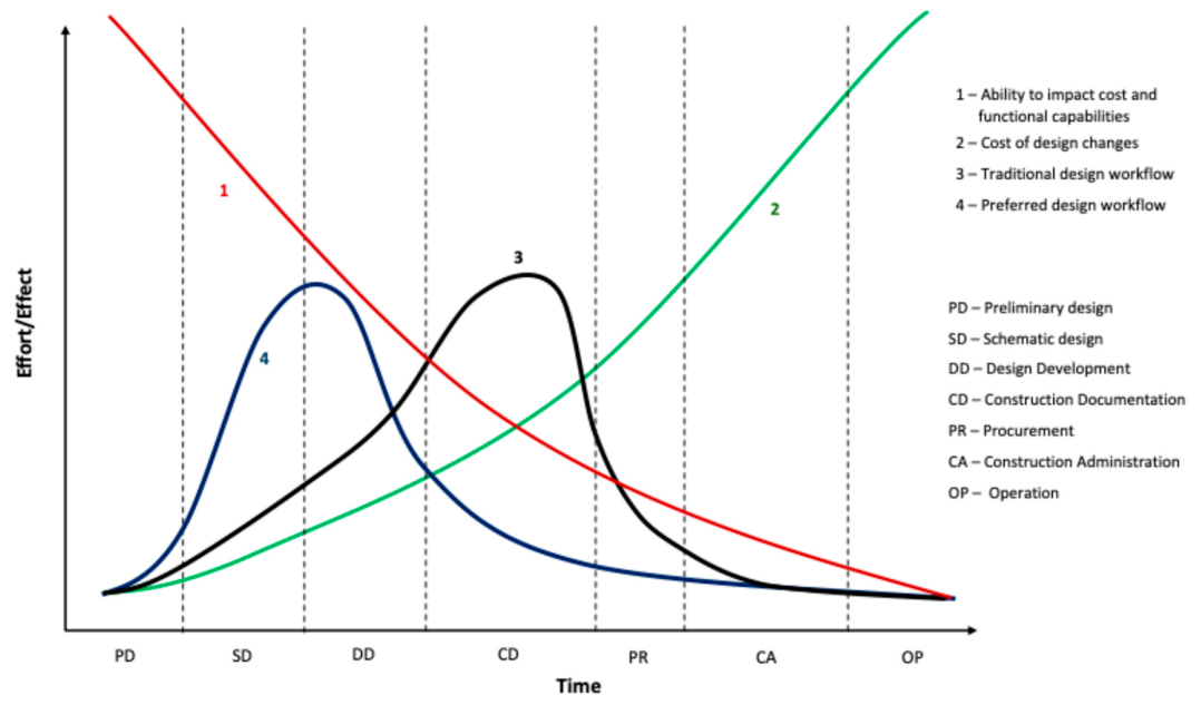
This aligns with MacLeamy’s theory (
Figure 1), which suggests that influence over project outcomes is greatest during the initial design phase, with modification costs increasing afterwards. Industrialised timber systems amplify this dynamic, as geometric decisions directly affect manufacturing feasibility. Early collaboration and collective decision-making are essential for aligning architectural intent, structural performance, and manufacturing principles before finalising downstream commitments [
25].
Digital modelling and simulation methodologies support the initial assessment of alternatives. Parametric modelling allows for ongoing adjustments in spans, member sizes, and modular configurations. Structural modelling offers an early performance evaluation. Optimisation techniques help compare different options based on multiple goals. In timber systems, these tools assist in optimising panels and modules, reducing material use, and early detection of limits that impact manufacturing processes [
26,
27]. However, analytical capacity alone does not solve fragmentation issues. When initial modelling is confined to discipline-specific environments, downstream stakeholders often must recreate geometry to suit their operational requirements.
Therefore, a research gap exists between the recognised importance of early decision-making and current industry practices, where continuous model development, file-based exchange, and document-driven approvals remain underexplored. Integration is often seen as a transfer event rather than a regulated process that includes established model authority, persistent identities, and traceable change management. Overcoming this gap requires redefining integration as a governance issue focused on geometric continuity across domains, rather than merely a technical matter of file compatibility.
2.3. Computational Design Workflows
Computational design environments have become valuable platforms for modelling, automation, and cross-platform integration. Visual programming tools like Grasshopper and Dynamo support rule-based geometry development, constraint encoding, hierarchical assembly logic, and seamless integration of changes across parameterised models. They offer direct access to software APIs, allowing automation of repetitive modelling tasks, systematic extraction of model data, and programmatic development of downstream representations [
12,
28].
Architects are increasingly adopting these systems to handle complex geometry and streamline design processes. However, the adoption among structural engineers and manufacturers remains highly limited, especially in Australian prefabricated timber sectors, where traditional workflows usually rely on BIM-to-document procedures in design and specialised Computer-Aided Design (CAD)/Computer-Aided Manufacturing (CAM) systems in manufacturing.
Both Grasshopper and Dynamo facilitate visual programming without needing traditional coding skills, while also supporting scripting elements (e.g., Python, C#) for customised logic when necessary [
29]. Dynamo is tightly integrated within the Revit ecosystem and offers the Revit API through a more user-friendly node-based interface, making it ideal for BIM automation, parameter handling, and systematic manipulation of Revit-native components [
30]. Grasshopper, combined with geometric kernel of Rhinoceros 7, is known for its high-performance geometric modelling, extensive plugin ecosystem, and flexibility in managing non-standard geometries and assembly attributes, establishing it as a leading computational environment for complex geometric modelling and automation workflows [
12,
29].
Importantly, these computational environments are no longer isolated modelling sandboxes. An increasingly evolved ecosystem of connectors, plugins, and APIs supports the integration of these environments with BIM authoring tools, structural analysis platforms, and manufacturing/digital fabrication toolchains. This ecosystem offers multiple pathways for integration, such as (i) direct in-process connection (where one tool operates “within” another), (ii) API-driven generation of downstream models, and (iii) structured exchange through neutral formats. These features facilitate the shift from “model transfer” to “model development,” where downstream models are created from a controlled parametric source rather than manually reconstructed [
12,
29].
In this ecosystem, several tools are commonly used in industry and research to connect parametric geometry with engineering and fabrication platforms. For example, Geometry Gym provides interoperability tools that link parametric geometry created in Grasshopper with BIM and structural analysis environments (such as BIM tools like Revit, Tekla, ArchiCAD, and structural analysis platforms like SAP2000, ETABS, Robot, Strand7, SpaceGASS). Vendor-specific integrations are also available through plugins and APIs that connect parametric environments to structural analysis platforms like Dlubal RFEM 6 [
31].
Timber-specific platforms within manufacturing processes are increasingly providing interfaces for geometry input and downstream detailing. Direct plugin-based connections facilitate the transfer of geometry to environments such as Cadwork (v2026) [
32,
33]. Additionally, hsbCAD functions directly within the Revit ecosystem, enabling fabrication-level modelling inside the BIM environment [
34]. Access to these platforms can be organised through Rhino.Inside.Revit, which allows Grasshopper to operate within Revit, or through Dynamo-based automation workflows, thus supporting controlled geometry exchange without the need for traditional export/import cycles.
In addition to interoperability, computational environments support early decision-making through rule-based geometry generation, preliminary structural assessment, environmental and performance evaluation, design-space exploration, and multi-objective optimisation. Structural analysis can be carried out using embedded Finite Element Modelling (FEM) plugins (e.g., Karamba 3D, Kangaroo, etc.), enabling early evaluations of stiffness, deflection, and member utilisation before developing detailed analytical models. Plugins for environmental and building performance within similar environments allow for initial scenario assessment [
28].
Multi-objective optimisation techniques (e.g., Galapagos, Octopus, etc.) can explore design alternatives under various constraints, aligning with the needs of industrialised construction where geometry must consistently meet architectural, structural, and manufacturing demands [
29,
35]. These capabilities are most effective when incorporated into a structured process that identifies early constraints and maintains consistent model updates across platforms.
Table 1 highlights the primary computational capabilities that facilitate integration in prefabricated timber workflows.
Despite these advantages, the systematic adoption of these methods remains limited in prefabricated timber workflows. The main limitations include fragmented discipline-specific workflows, limited governance of shared model authority, proprietary software dependencies, uneven computational skills across project teams, and the continued reliance on document-based approval processes.
Computational design is widely used for generating complex architectural forms, but is less often used as a shared integration backbone that connects architects, engineers, and manufacturers. In Australian prefabricated timber practice, parametric environments are rarely formalised as cross-disciplinary governance layers. Instead, they are applied selectively within individual disciplines. This motivates the need for a digital integration framework that defines geometry authority, captures multidisciplinary constraints early, formalises integration pathways, and ensures that downstream models are derived from, rather than reconstructed independently of, a governing parametric source.
3. Methodology
This study establishes a framework for digital integration from design to manufacturing in prefabricated timber construction, focused on a geometry-centric parametric backbone. The approach combines evidence-based requirement definition, framework synthesis, and technical demonstration to verify that the proposed workflow supports cross-platform continuity without depending on downstream geometry reconstruction.
The development of the framework is based on two foundational knowledge sets. The main source is empirical evidence based on industry practices, gathered from previous studies of prefabricated timber projects and workflows. The findings highlighted persistent integration issues, such as fragmented toolchains, repeated re-modelling across disciplines, inadequate early integration of manufacturing constraints, and poor feedback between design, engineering, and manufacturing processes.
The second source is the research literature on BIM interoperability, model-based delivery, and computational design, which highlights current limitations of file-based exchange and recognises parametric modelling as an approach for encoding rules and constraints early, while enabling controlled model development. Overall, these inputs suggest that the main challenge in integration is the lack of a clear model authority and consistent geometry continuity across platforms, rather than only software compatibility.
A framework of integration requirements has been developed to address the structural fragmentation observed in prefabricated timber processes. These requirements guided the development of a digital integration framework for design-to-manufacturing, aimed at enhancing geometric continuity, establishing model authority, and incorporating multidisciplinary constraints early in the project. The framework was developed to minimise downstream geometry re-authoring and to standardise cross-platform coordination procedures.
A demonstrative implementation was carried out to assess the technical viability of the proposed integration framework. The technical demonstration followed a structured sequence. First, a parametric timber module was generated in Grasshopper using dimensional, replication, storey, and opening parameters. Second, the generated geometry was connected to Dlubal and Cadwork through plugin-based integration pathways. Third, selected parameters were modified in the source model to examine whether downstream representations could be regenerated consistently. This sequence was used to assess integration behaviour across repeated parameter-update scenarios within the controlled demonstrator.
The evaluation focused on the practicality of integration rather than physical performance, detailed structural analysis, or production-level manufacturing outcomes. The study was therefore framed as a proof-of-concept technical demonstration, not as a full project-scale productivity assessment.
Accordingly, time savings, cost savings, and statistical error reduction were not directly measured. Instead, the validation considered observable process-based indicators, including geometry consistency, downstream re-authoring requirements, parameter update integration, dimensional consistency, object mapping where supported, and downstream model usability. This validation scope aligns with the aim of assessing the technical feasibility of a parametric, geometry-centric integration workflow for design-to-manufacturing coordination.
4. Results
4.1. Design-to-Manufacturing Integration Framework
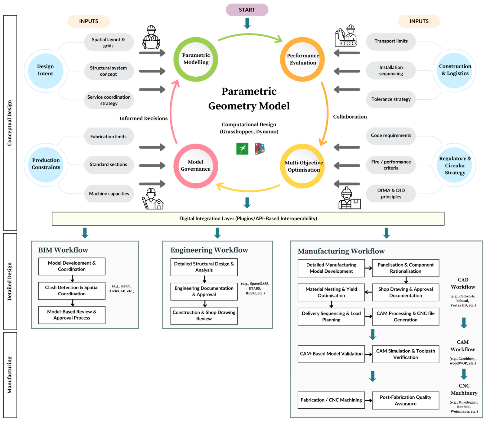
The proposed framework offers a structured digital integration workflow from design to manufacturing for prefabricated timber construction. It aims to address the systemic fragmentation seen in current practice, where architectural modelling, structural engineering, and manufacturing detailing are often carried out in discipline-specific environments with limited continuity of geometric authority. Traditional workflows rely heavily on file exchanges and document-based approvals, which can lead to geometry reinterpretation, attribute loss, and re-modelling downstream. The framework shown in
Figure 2 redefines integration as a governed geometric process, where an authoritative parametric model serves as the central coordination tool across project stages. Instead of replacing specialised tools, it formalises how they connect to a shared geometric source.
4.1.1. Early-Stage Multidisciplinary Collaboration for Integration
The conceptual design phase is redefined as the key integration stage of the project lifecycle. Instead of mainly serving as a phase of architectural development, it is designed as a collaborative process that incorporates constraints and stakeholder inputs before finalising the geometry.
Figure 2 combines these inputs into four interconnected domains, such as design intent, production constraints, construction and logistical considerations, and regulatory and circular strategies.
The design intent covers spatial arrangements, grid frameworks, structural principles, and service integration strategies that establish the foundation of the project. Manufacturing constraints include fabrication limitations, standard dimensions, and machine capabilities that determine manufacturability limits. Construction and logistics inputs address transportation constraints, installation sequencing, and tolerance methods, which influence modular dimensions and assembly practicality. The regulatory and circular strategy encompasses code requirements, fire and performance standards, along with Design for Manufacture and Assembly (DfMA) and Design for Disassembly (DfD) principles to ensure compliance and circularity objectives are integrated into the initial geometric definition.
These inputs are depicted within a computational design environment that operates as the primary geometric layer. The parametric model is structured as a rule-based system where connections and constraints are clearly defined by parameters. This approach allows for controlled changes and systematic evaluation of assemblies before making further commitments downstream. Iterative processes revolve around this geometric foundation to support informed decision-making.
Parametric modelling facilitates quick adjustments of module dimensions and assemblies within specified constraints. Performance evaluation allows for initial analytical assessments as needed. Multi-objective optimisation supports the analysis of alternatives considering structural, spatial, and manufacturing factors. Model governance procedures define parameter control, stabilisation thresholds, and responsibility allocation to promote transparency of the authoritative geometric model. Collectively, these methods transition conceptual design into a convergence phase where geometry is collaboratively refined alongside manufacturing considerations from the outset.
4.1.2. Cross-Platform Digital Integration Layer
Following geometry stabilisation, the framework shifts to a digital integration layer that formalises cross-platform propagation. Integration is defined as controlled model derivation rather than file transfer. Plugins and API-based approaches enable the programmatic creation of geometry and related parameters within specialised platforms, maintaining connections between upstream parameters and downstream representations.
Structural analysis platforms then use this finalised geometry for detailed engineering design, while manufacturing design platforms incorporate fabrication-specific attributes necessary for production. However, both operate on models derived from a shared parametric source. This method reduces reliance on neutral file exchange as the main integration strategy and prevents geometric misalignment caused by manual reconstruction.
The digital integration layer establishes structured links between the parametric backbone and BIM authoring tools, structural analysis software, and timber-specific manufacturing platforms. These links do not eliminate disciplinary specialisation but regulate the process in which geometry is utilised and developed. Changes to governing parameters can be systematically communicated, reducing repetition and enhancing coordination across domains.
4.1.3. Model Derivation Across Discipline Platforms for Detailed Design
During the detailed design phase, domain workflows are maintained while being redefined in relation to the geometry backbone. The BIM workflow includes coordinated model development, clash detection, and model-based review processes based on the geometry backbone. The engineering workflow encompasses detailed structural analysis, documentation creation, and drawing validation. The fabrication workflow covers manufacturing modelling, penalisation and component rationalisation, shop drawing development, nesting, and yield optimisation, as well as preparation for CAM processing. Unlike traditional practice, these workflows are not isolated modelling activities but are downstream developments of a stabilised geometric definition.
The manufacturing phase encompasses CAM validation, simulation, toolpath verification, CNC file creation, machining, and post-fabrication quality checks. Geometry is regarded as finalised before this stage, indicating that production and logistics constraints have been integrated earlier. By moving constraint adjustments to an earlier stage, the framework reduces the need for late redesigns and allows a smoother shift from digital models to physical production. As a result, manufacturing becomes a process focused on delivery rather than a stage for corrective redesign.
The framework offers a geometry-focused integration structure that improves design-to-manufacturing continuity in prefabricated timber construction through early constraint application, organised parametric modelling, and controlled digital generation.
4.2. Demonstration of the Geometry-Centric Integration Framework
4.2.1. Parametric Geometry Modelling and Governance Logic
A modular-scale parametric timber model was created within a computational design environment to evaluate the proof-of-concept feasibility of the proposed framework. The model was designed to explore geometry governance, cross-platform consistency, and real-time integrated behaviour, rather than assess structural performance or fabrication details.
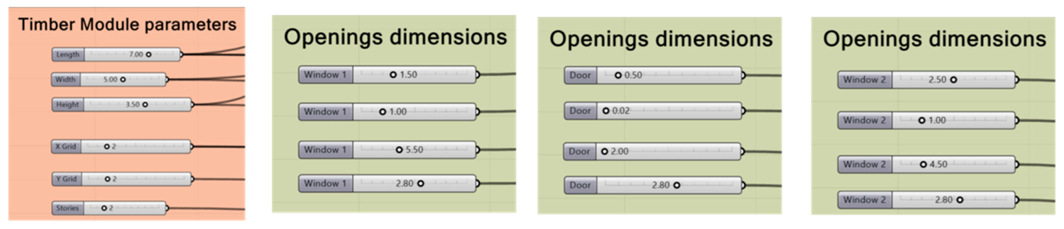
The module was defined using a set of input parameters based on primary dimensional variables such as length, width, and height. These primary dimensions established the basic geometric structure. Additionally, replication parameters were introduced to simulate scalable prefabricated configurations. Adjustable grid inputs allowed modules to be generated sequentially along the X and Y directions. A storey parameter-controlled vertical stacking along the Z direction, enabling multi-storey assemblies to be derived from the same base definition. The openings were also parameterised based on width, height, and offsets.
The complete set of input parameters used in the demonstration model is shown in
Figure 3. Although the current implementation concentrates on geometric dimensions and replication modules, the parameter inputs can be expanded. Other variables, such as material type, cross-sectional dimensions, structural spacing rules, and fabrication tolerances, can be added within the same framework. This framework demonstrates how early-stage multidisciplinary collaboration can be promoted through parameter definition, reducing the need for downstream adjustments.
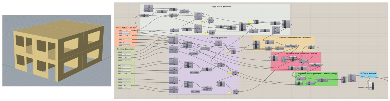
The parametric model was created using a visual programming workflow, with Grasshopper managing geometry development within the Rhino modelling environment.
Figure 4 shows the complete Grasshopper script alongside the resulting 3D model. The script produces geometry where input parameters specify envelope creation, subdivision, panel segmentation, and opening configurations through rule-based relationships to define the geometry.
The geometric relationships were directly defined as part of the parametric definition process. Changes to primary dimensions automatically modified panel boundaries, opening arrangements, and module alignment across replicated instances. Iterative generation along horizontal and vertical axes was governed by controlled logic, ensuring consistent spacing and geometric uniformity. The model operated as a linked parametric system, where all geometry depended on a specific set of governing parameters. This organised dependency structure offers a single authoritative geometry source that can incorporate iterative input from stakeholders during the initial phase of integration.
4.2.2. Cross-Platform Integration with Structural and Manufacturing Environments
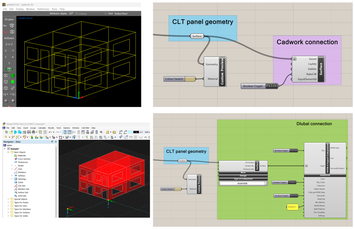
The modified geometry was connected to both a structural analysis platform (Dlubal) and a timber-specific manufacturing platform (Cadwork) using plugin-based interoperability tools within the computational environment to evaluate integration response. The purpose of this stage was to examine whether the geometry generated from the parametric source could be transferred to downstream discipline-specific environments without rebuilding the base model manually.
Figure 5 shows the continuous visualisation of the model in Rhino/Grasshopper, Dlubal, and Cadwork, including the integration components employed by Grasshopper to enable these connections.
The generated model was recognised as an analytical representation suitable for engineering analysis within the structural environment. In the manufacturing context, the transferred geometry provided the basis for downstream fabrication-oriented modelling. Although detailed analytical settings, CNC-ready information, joinery rules, automated nesting, and production sequencing were not fully validated within the current proof-of-concept, the primary geometric arrangement remained aligned with the governed parametric source across both downstream environments.
In conventional design-to-analysis workflows, structural engineers often need to reinterpret architectural geometry and rebuild an analytical model within structural analysis software before assigning engineering-specific information. In the proposed workflow, the primary geometry, including member positions, dimensional relationships, and overall configuration, is derived from the governed parametric source and transferred to Dlubal. This allows the structural modeller to focus on analytical enrichment, such as material properties, supports, load cases, member releases, and structural verification, rather than recreating the base geometry from the beginning.
Similarly, in conventional design-to-manufacturing workflows, manufacturing modellers often need to reinterpret architectural or engineering drawings and rebuild geometry within timber-specific modelling software before fabrication-level information can be added. In the proposed workflow, the governed parametric geometry is transferred to Cadwork as a downstream manufacturing-oriented model. This allows the manufacturing modeller to focus on fabrication-specific development, such as connection detailing, material assignment, nesting preparation, machining information, and production sequencing, rather than recreating the tested base geometry from the beginning.
4.2.3. Process-Based Assessment of Integration Performance
The integration performance was assessed using process-based indicators aligned with the framework objectives. As this was a proof-of-concept demonstration, project-level time savings and statistical error reduction were not measured. The assessment instead focused on geometry consistency, downstream re-authoring requirements, parameter update integration, dimensional consistency, object mapping where supported, and model usability.
Parameter changes, including module width, X and Y replication, storey count, and opening dimensions, were introduced in the governing Grasshopper definition. The resulting updates were reflected in both Dlubal and Cadwork without manually redrawing the tested primary geometry. This indicates that, within the demonstrated workflow, downstream reconstruction of the base geometry was replaced by controlled model derivation from the parametric source.
Although the demonstrated model operates at a modular scale and lacks full production-scale details, it confirms the technical feasibility of geometry-governed integration within the tested software ecosystem. The study indicates that parametric modelling can extend beyond conceptual analysis and serve as a systematic digital framework connecting design, engineering, and manufacturing sectors in prefabricated timber construction. Further validation using real project workflows, repeated design-change scenarios, and industrial-scale prefabricated timber models is required to quantify time savings, error reduction, and production impacts.
5. Discussion
5.1. Geometry Governance in Fragmented Industry Workflows
Current prefabricated timber workflows continue to be characterised by fragmented digital practices. Architectural modelling, structural engineering, and manufacturing detailing are often carried out in isolated software environments, with coordination mainly relying on file exchanges and document-based approvals. Industry challenges include repeated re-modelling across different platforms, late integration of fabrication constraints, weak feedback loops between design and production teams, and uncertainty over model responsibility.
The key challenges in current prefabricated timber workflows and the responses proposed in the framework are summarised in
Table 2. These challenges do not arise solely from technical incompatibility but also from the lack of a structured governance framework to manage the development of geometry across stages.
This proposed framework addresses this fundamental issue by developing parametric geometry as the primary medium of coordination. Instead of transferring static models between domains, geometry is controlled within a rule-based system from which discipline-specific models are created. Re-modelling is avoided by treating geometry as a governed system of relationships that can be consistently applied across structural and manufacturing platforms. The demonstration model confirms that changes made at the governing level are reliably integrated across environments, thereby reducing geometry drift and preventing duplication of modelling efforts.
The late coordination of manufacturing information has been a persistent issue in prefabricated timber processes. Manufacturing constraints, logistical limitations, and sequencing issues are often incorporated after the design and structural models are well developed, leading to redesigns when flexibility is limited. The framework shifts decision-making to the early project stages by integrating production constraints into the conceptual parametric model.
Limited bidirectional feedback between design and manufacturing contributes to ongoing inefficiencies in current prefabrication workflows, where information exchange often takes place through manual file transfers even when digital integration technologies are accessible. The proposed framework facilitates coordination using a regulated parametric model, enabling discipline-specific integration that reduces rework and enhances cross-platform consistency while preserving detailed domain modelling independence.
5.2. Parametric Modelling as an Integration Mechanism
The findings show that parametric modelling functions both as a tool for exploring design options and as a method to coordinate information across disciplines such as design, engineering, and manufacturing. The proposed approach defines geometry using rule-based relationships, allowing discipline-specific models to be created from a single, integrated computational source rather than being developed separately. This framework enables different software environments to maintain their own representations while staying consistently linked to the main parametric structure.
The proposed framework differs from existing parametric-BIM and manufacturing-oriented workflows by focusing on geometry governance rather than isolated model exchange or tool-specific automation. IFC-based workflows provide an important mechanism for openBIM data exchange, while tools such as Revit, hsbCAD, Cadwork, Rhino. Inside. Revit, and GeometryGym support modelling, translation, and fabrication-oriented information transfer within specific software environments. However, these approaches do not, by themselves, establish a continuous source of geometric authority across architectural design, structural rationalisation, manufacturing modelling, and CNC preparation.
In practice, exchanged models often require re-modelling, manual enrichment, verification, and correction before they become suitable for fabrication. This is particularly critical in prefabricated timber construction, where manufacturing-readiness depends not only on object geometry, but also on member classification, tolerances, connection zones, material orientation, machining logic, and revision control.
Therefore, the proposed framework positions existing tools as components within a broader parametric integration workflow. Its contribution is to organise these tools around a governed parametric geometry backbone that maintains geometric continuity, embeds manufacturing constraints earlier in the design process, and supports more reliable design-to-manufacturing information flow.
This framework transforms the role of computational design environments from solely being generative modelling platforms to becoming integration infrastructure that supports digital continuity throughout project phases. While current interoperability methods mainly focus on file sharing and schema alignment, the presented workflow demonstrates that controlled parametric derivation can minimise geometry reinterpretation and facilitate coordinated model updates across different platforms. Such an approach is especially relevant for prefabricated timber construction, where geometric consistency, modular repetition, and manufacturing constraints strongly influence downstream detailing and production processes.
5.3. Computational Capabilities and Implications for Industry Adoption
The demonstration further highlights the significance of computational design environments in enabling integrated workflows through rule-based modelling, multidisciplinary constraint assessment, and programmatic integration with downstream software. These capabilities facilitate the early incorporation of production constraints, initial evaluation of design alternatives, and automated creation of discipline-specific models through API-based interfaces. Therefore, the need for repeated manual model rebuilding is reduced, while maintaining the flexibility essential for domain-specific detailing and analysis.
From an industry perspective, the framework can be adopted progressively rather than requiring a complete restructuring of existing toolchains. A parametric backbone can initially support integration between conceptual modelling and one downstream environment, such as structural analysis or manufacturing detailing, before extending to additional platforms as organisational capability develops.
This approach maintains compatibility with existing BIM and documentation practices while gradually introducing a model-centric workflow in which geometric relationships remain consistent across disciplines. For prefabricated timber systems, where manufacturing constraints, modular coordination, and dimensional accuracy are critical, such an integration strategy provides a practical pathway towards more integrated design-to-manufacturing workflows.
5.4. Limitations and Future Works
The current study concentrated on validating geometry governance and cross-platform integration behaviour rather than comprehensive analytical or production optimisation. The model demonstrated was aimed at assessing model consistency, controlled development, and real-time update integration. Both technological and operational aspects require further development and validation at an industrial scale, as shown in
Table 3.
The study uses a computational design platform that enables the direct definition of materials, supports, and load combinations, along with integrated finite element analysis through existing plugins. These capabilities can be incorporated within the same geometry-driven framework and systematically transferred to specialised structural platforms. This integration would further minimise re-authoring during the detailed design stage.
Additionally, manufacturing-focused optimisation processes could be integrated earlier, enhancing the framework to establish a fully continuous digital connection. These optimisation processes could include automated checking of structural suitability, manufacturability constraints, material efficiency, nesting, transport requirements, sequencing, and production feedback within the same parametric workflow. Future studies should focus on analytical completeness, production optimisation, industrial validation, and governance formalisation to deliver an extended implementation that fully operationalises DfMA and DfD in industrial practice.
6. Conclusions
Prefabricated timber construction increasingly relies on digital modelling environments. However, ongoing fragmentation across design, engineering, and manufacturing processes continues to reduce workflow efficiency. Re-modelling, late-stage design changes, and document-driven coordination remain fundamental barriers that prevent the realisation of fully integrated design-to-manufacturing workflows. These issues reflect not only limitations in software interoperability but also the absence of a well-defined geometric authority across project stages.
This study presents a geometry-focused digital integration framework that establishes a parametric modelling environment as the main coordinating backbone. By considering multidisciplinary limitations during conceptual design and enabling regulated cross-platform model derivation through plugins and API procedures, the framework redefines integration as a governance process rather than a file exchange process. A parametric mass timber module was developed to assess this approach.
The proof-of-concept demonstration showed that dimension changes and replication logic defined within the governing model could be propagated across the tested structural and manufacturing platforms. Within this modular-scale workflow, the tested primary geometry was updated without manual re-authoring in the downstream environments. The results support the technological feasibility of geometry-driven integration within existing software ecosystems.
The framework shows technical feasibility while redefining parametric modelling as an infrastructure that integrates prefabricated timber workflows. Including manufacturing information and regulatory aspects early on improves the link between digital design goals and real-world fabrication. While further work is needed to fully incorporate analytical definitions, optimise manufacturing, and validate on an industrial scale, the results show that geometry-focused governance offers a practical way to achieve more consistent, model-driven, and manufacturing-aligned prefabricated timber delivery. This framework provides a foundation for improving digital continuity across the design-to-production process in timber construction.
Author Contributions
Conceptualization, S.S. and T.G.; methodology, S.S. and T.G.; software, S.S.; validation, S.S.; formal analysis, S.S.; investigation, S.S. and T.G.; data curation, S.S.; writing—original draft preparation, S.S.; writing—review and editing, S.S., T.G., P.M. and D.W.B.; visualization, S.S.; supervision, T.G., P.M. and D.W.B.; project administration, T.G. and P.M.; funding acquisition, T.G., P.M. and D.W.B. All authors have read and agreed to the published version of the manuscript.
Funding
This research was funded by the University of Melbourne Research Scholarship and the Australian Research Council Industrial Transformation Research Program (ITRP)—Research Hub IH220100016: ARC Research Hub to Advance Timber for Australia’s Future Built Environment.
Institutional Review Board Statement
Not applicable.
Informed Consent Statement
Not applicable.
Data Availability Statement
The data presented in this study are available on request from the corresponding author. All data are contained within the article.
Acknowledgments
The authors gratefully acknowledge the Department of Infrastructure Engineering at the University of Melbourne and the School of Architecture and Urban Design at RMIT University for their valuable support, resources, and academic environment. The authors also thank colleagues and collaborators for their constructive feedback throughout the development of this study.
Conflicts of Interest
The authors declare no conflicts of interest.
Abbreviations
The following abbreviations are used in this manuscript:
| BIM | Building Information Modelling |
| CNC | Computer Numerical Control |
| IFC | Industry Foundation Classes |
| API | Application Programming Interface |
| CAD | Computer-Aided Design |
| CAM | Computer-Aided Manufacturing |
| FEM | Finite Element Modelling |
| DfMA | Design for Manufacture and Assembly |
| DfD | Design for Disassembly |
References
- Guerra, B.C.; Shahi, S.; Mollaei, A.; Skaf, N.; Weber, O.; Leite, F.; Haas, C. Circular economy applications in the construction industry: A global scan of trends and opportunities. J. Clean. Prod. 2021, 324, 129125. [Google Scholar] [CrossRef] [Scilit]
- Gunawardena, T.; Mendis, P. Prefabricated Building Systems—Design and Construction. Encyclopedia 2022, 2, 70–95. [Google Scholar] [CrossRef] [Scilit]
- Wasim, M.; Vaz Serra, P.; Ngo, T.D. Design for manufacturing and assembly for sustainable, quick and cost-effective prefabricated construction—A review. Int. J. Constr. Manag. 2022, 22, 3014–3022. [Google Scholar] [CrossRef] [Scilit]
- Ahn, N.; Dodoo, A.; Riggio, M.; Muszynski, L.; Schimleck, L.; Puettmann, M. Circular economy in mass timber construction: State-of-the-art, gaps and pressing research needs. J. Build. Eng. 2022, 53, 104562. [Google Scholar] [CrossRef] [Scilit]
- Roxas, C.L.C.; Bautista, C.R.; Dela Cruz, O.G.; Dela Cruz, R.L.C.; De Pedro, J.P.Q.; Dungca, J.R.; Lejano, B.A.; Ongpeng, J.M.C. Design for Manufacturing and Assembly (DfMA) and Design for Deconstruction (DfD) in the Construction Industry: Challenges, Trends and Developments. Buildings 2023, 13, 1164. [Google Scholar] [CrossRef] [Scilit]
- Cao, J.; Vakaj, E.; Soman, R.K.; Hall, D.M. Ontology-based manufacturability analysis automation for industrialized construction. Autom. Constr. 2022, 139, 104277. [Google Scholar] [CrossRef] [Scilit]
- Chong, O.W.; Baker, C.; Afsari, K.; Zhang, J.; Roach, M. Integration of BIM Processes in Architectural Design, Structural Analysis, and Detailing: Current Status and Limitations. In Proceedings of the Construction Research Congress 2020; American Society of Civil Engineers: Tempe, AZ, USA, 2020; pp. 1203–1212. [Google Scholar]
- Sriram, A.G.; Subramani, R.; Rusho, M.A.; Sharma, S.; T, R.; Mahapatro, A.; Ismail, A.I. MCDM approaches in BIM-driven decision-making modelsin enhancing energy efficiency for sustainable 3D-printedinfrastructure in the construction industry. Environ. Prog. Sustain. Energy 2025, 44, e70121. [Google Scholar] [CrossRef] [Scilit]
- Zhang, Z.; Tan, Y.; Shi, L.; Hou, L.; Zhang, G. Current State of Using Prefabricated Construction in Australia. Buildings 2022, 12, 1355. [Google Scholar] [CrossRef] [Scilit]
- Lobos Calquin, D.; Mata, R.; Correa, C.; Nuñez, E.; Bustamante, G.; Caicedo, N.; Blanco Fernandez, D.; Díaz, M.; Pulgar-Rubilar, P.; Roa, L. Implementation of Building Information Modeling Technologies in Wood Construction: A Review of the State of the Art from a Multidisciplinary Approach. Buildings 2024, 14, 584. [Google Scholar] [CrossRef] [Scilit]
- Nguyen, D.; Jeon, C.; Roh, G.; Shim, C. BIM-based preassembly analysis for design for manufacturing and assembly of prefabricated bridges. Autom. Constr. 2024, 160, 105338. [Google Scholar] [CrossRef] [Scilit]
- Seghier, T.E.; Khosakitchalert, C.; Liu, Z.; Ohueri, C.C.; Lim, Y.-W.; Bin Zainazlan, A.F. From BIM to computational BIM: A systematic review of visual programming application in building research. Ain Shams Eng. J. 2025, 16, 103173. [Google Scholar] [CrossRef] [Scilit]
- Alfieri, E.; Seghezzi, E.; Sauchelli, M.; Di Giuda, G.M.; Masera, G. A BIM-based approach for DfMA in building construction: Framework and first results on an Italian case study. Archit. Eng. Des. Manag. 2020, 16, 247–269. [Google Scholar] [CrossRef] [Scilit]
- Orlowski, K. Assessment of Manufacturing Processes for Automated Timber-Based Panelised Prefabrication. Buildings 2019, 9, 125. [Google Scholar] [CrossRef] [Scilit]
- Darwish, M.; Alsakka, F.; Assaf, S.; Al-Hussein, M. Automated BIM-based CNC file generator for wood panel framing machines in construction manufacturing. In Proceedings of the Modular and OƯsite Construction (MOC) Summit 2022, Edmonton, AB, Cananda, 27–29 July 2022; pp. 98–105. [Google Scholar] [CrossRef] [Scilit]
- Orlowski, K. Automated manufacturing for timber-based panelised wall systems. Autom. Constr. 2020, 109, 102988. [Google Scholar] [CrossRef] [Scilit]
- Australian Sustainable Hardwoods Pty Ltd. MASSLAM Brochure; Australian Sustainable Hardwoods Pty Ltd.: Heyfield, Australia, 2025. [Google Scholar]
- NeXTimber® by Timberlink. NeXTimber® Documentation Guide; NeXTimber® by Timberlink: Tarpeena, Australia, 2024. [Google Scholar]
- XLam. XLam Shop Detailing Guide; XLam: Hamilton, Australia, 2020. [Google Scholar]
- Aberger, E.; Koppelhuber, J.; Heck, D. Building information modeling in timber construction—A solution for planning process, design phases and the unification of scope of works. In Proceedings of the World Conference on Timber Engineering (WCTE 2018), Seoul, Republic of Korea, 20–23 August 2018. [Google Scholar]
- Zabin, A.; González, V.A.; Zou, Y.; Amor, R. Applications of machine learning to BIM: A systematic literature review. Adv. Eng. Inform. 2022, 51, 101474. [Google Scholar] [CrossRef] [Scilit]
- Wang, M.; Li, X.; Li, F.; Wang, J. Research on Design of Modular Apartment Building Product Platform for Manufacture and Assembly: A Case Study of the Modular Dormitory Building Design Project. Buildings 2025, 15, 3585. [Google Scholar] [CrossRef] [Scilit]
- Montazeri, S.; Lei, Z.; Odo, N. Design for Manufacturing and Assembly (DfMA) in Construction: A Holistic Review of Current Trends and Future Directions. Buildings 2024, 14, 285. [Google Scholar] [CrossRef] [Scilit]
- Gao, S.; Jin, R.; Lu, W. Design for manufacture and assembly in construction: A review. Build. Res. Inf. 2020, 48, 538–550. [Google Scholar] [CrossRef] [Scilit]
- Walasek, D.; Barszcz, A. Analysis of the Adoption Rate of Building Information Modeling [BIM] and its Return on Investment [ROI]. Procedia Eng. 2017, 172, 1227–1234. [Google Scholar] [CrossRef] [Scilit]
- Rojas Wettling, C.; Mourgues Alvarez, C.; Guindos Bretones, P. IDM for the Conceptual Evaluation Process of Industrialized Timber Projects. Adv. Civ. Eng. 2023, 2023, 9200255. [Google Scholar] [CrossRef] [Scilit]
- Rezaei Rad, A.; Burton, H.; Rogeau, N.; Vestartas, P.; Weinand, Y. A framework to automate the design of digitally-fabricated timber plate structures. Comput. Struct. 2021, 244, 106456. [Google Scholar] [CrossRef] [Scilit]
- Manterola-Ubillos, M.; Gonzalez-Quintial, F.; Rico-Martinez, J.M.; Benito Ayucar, J.; Begiristain-Mitxelena, J.A. Analysis of Planar Double-Layer Timber Spatial Frames by Using Parametric Tools. Appl. Sci. 2024, 14, 6400. [Google Scholar] [CrossRef] [Scilit]
- Leitão, A.; Santos, L.; Lopes, J. Programming Languages for Generative Design: A Comparative Study. Int. J. Archit. Comput. 2012, 10, 139–162. [Google Scholar] [CrossRef] [Scilit]
- Mousiadis, T.; Mengana, S. Parametric BIM: Energy Performance Analysis Using Dynamo for Revit. Master’s Thesis, KTH Royal Institute of Technology, Stockholm, Sweden, 2016. [Google Scholar]
- Wallin, D.; Wasberg, M. Parametric Design of Building Structures in Cooperation with Architects: Usage and Evaluation of Structural Plug-Ins in 3D Visualisation Software. Master’s Thesis, KTH Royal Institute of Technology, Stockholm, Sweden, 2016. [Google Scholar]
- Cadwork. Cadwork, Version 30; Cadwork: Herisau, Switzerland, 2023. Available online: https://cadwork.de/wp-content/uploads/2023/07/News3D_30.0_en.pdf (accessed on 14 January 2026).
- Cadwork. Solutions for Timber Construction, Joinery & Interior Design; Cadwork: Herisau, Switzerland, 2024; Available online: https://en.04.cadwork.com/wp-content/uploads/2024/11/Brochure-2021_EN_light-B-1.pdf (accessed on 25 November 2025).
- hsbcad. 3D CAD/CAM—An Indispensable Asset for the Offsite Construction Industry; hsbcad: Gent, Belgium, 2020; Available online: https://www.hsb-cad.com/Download/AU2020/brochure%20hsb%20English%20PUB_revised.pdf (accessed on 14 January 2026).
- Makris, M.P. Structural Design Tool for Performative Building Elements: A Semi-Automated Grasshopper Plugin for Design Decision Support of Complex Trusses. Master’s Thesis, University of Southern California, Los Angeles, USA, 2013. [Google Scholar]
| Disclaimer/Publisher’s Note: The statements, opinions and data contained in all publications are solely those of the individual author(s) and contributor(s) and not of MDPI and/or the editor(s). MDPI and/or the editor(s) disclaim responsibility for any injury to people or property resulting from any ideas, methods, instructions or products referred to in the content. |