Article

Stability and Maximum Power Point Operation of Induction-Generator Wind Turbines with Stator-Side Frequency Control


by
Cristian Paul Chioncel
1,
Gelu-Ovidiu Tirian
2 and
Elisabeta Spunei
1,*
1
Department of Engineering Sciences, Faculty of Engineering, Babes-Bolyai University, 400028 Cluj-Napoca, Romania
2
Faculty of Engineering Hunedoara, Polytechnic University of Timisoara, 300006 Timisoara, Romania
*
Author to whom correspondence should be addressed.
Appl. Sci. 2026, 16(12), 5970; https://doi.org/10.3390/app16125970
Submission received: 14 April 2026 / Revised: 30 May 2026 / Accepted: 11 June 2026 / Published: 12 June 2026
(This article belongs to the Special Issue Advances in Coastal Environments and Renewable Energy)

Abstract

Maintaining stable operation and maximum power extraction in wind turbines under significant wind speed variations remains a key challenge in wind energy systems. This study aims to analyze the stability and maximum power point operation of a wind turbine equipped with a squirrel-cage induction generator using stator-side frequency control. This study examines the operational performance of medium-power wind turbines in the kilowatt range under significant wind speed variability. The analysis focuses on a turbine equipped with a squirrel-cage induction generator and a control architecture that incorporates a power converter integrated into the stator circuit. The findings show that adjusting the stator frequency through the converter allows the generator to track the optimal rotational speed, ensuring operation at the maximum power point across a wide range of wind conditions. Based on these results, the study defines the stable operating region of the turbine under time-varying wind speeds, making it suitable for distributed energy projects in coastal regions where wind can be highly variable. It also shows that, for a given electrical load, the generator must be calibrated to an appropriate maximum stator frequency to maintain stable and efficient energy conversion.

1. Introduction

Electricity generation from renewable energy sources has become a significant component of the energy mix in Romania and Europe. In 2024, 46.9% of electricity in the European Union (EU) was produced from renewable sources [1]. The share of renewables in Romania’s electricity production in 2024 exceeded the EU average, reaching 50%. Among the categories of renewable energy sources at the EU level, wind energy holds the largest share at 39.1%, followed by hydroelectric power (29.9%) and solar power (22.4%) [1].
There are various solutions for utilizing wind energy: either through independent wind farms or by integrating them with other renewable energy sources. For instance, ref. [2] proposes the use of a wind turbine (WT) alongside a pumped-storage hydroelectric power plant. Simulations have shown that such a power plant effectively maintains the proper functioning of the energy system, even with fluctuations in wind speed and changes in load values [3]. In other scenarios, particularly in isolated and developing rural areas, the implementation of a wind energy system with hydroelectric energy storage via pumping from an open well is suggested [4]. Additionally, ref. [5] proposes a hybrid power facility that integrates thermal energy, wind power, photovoltaic (PV), and hydroelectric energy production, all facilitating stable operation of the energy system. In the case of wind systems, the choice of a specific type of wind turbine is made based on the characteristics of the area [6,7].
The efficient utilization of wind turbines (WTs) depends strongly on their deployment in locations with appropriate wind resources. Each wind farm exhibits distinct operational characteristics influenced by factors such as air density, local weather conditions, and blade deformation effects [8]. Accurately characterizing the aerodynamic behavior of wind turbines, which is often nonlinear and highly sensitive to environmental variations, is essential, as demonstrated in previous studies [9,10], which highlight the complexity of aerodynamic power conversion under variable operating conditions. Achieving maximum energy capture under varying operating conditions requires establishing a periodic relationship between the optimal mechanical angular speed and the corresponding wind velocity. This relationship is typically derived from mathematical models calibrated using experimental field data.
Wind speed is commonly monitored using small auxiliary wind turbines or sensors mounted on the nacelle [11,12]. However, nacelle-mounted sensors may not accurately reflect the wind speed acting directly on the rotor blades. In such cases, wind speed can be inferred by estimating torque and rotor speed and applying the inverse aerodynamic model of the turbine [13]. To ensure maximum electrical energy production, the turbine must operate at the maximum power point (MPP) across a wide range of wind speeds, independent of system configuration, as demonstrated in [14,15,16]. These works focus on maximum power point tracking (MPPT) strategies aimed at improving energy extraction under variable wind conditions. This requirement underscores the importance of analyzing turbine power curves under different wind conditions and determining the corresponding optimal power curve, as investigated in [17,18].
In addition, wind turbine operation has been extensively studied using various control strategies and monitoring techniques [19,20], which address system performance, dynamic behavior, and efficiency under fluctuating operating conditions. For instance, extended optimal torque control has demonstrated improvements of 2–7% in wind speed estimation accuracy and a 0.35% increase in energy efficiency [21]. PID-based controllers enable effective regulation of output power under fluctuating wind and load conditions, contributing to voltage stability [22]. For permanent-magnet synchronous generators, dual-loop control—combining torque and pitch regulation—has been recommended to enhance output power and overall energy yield [23]. Recent investigations have also examined the influence of power oscillation controllers on turbine structural dynamics, showing that their impact is comparable to wind-induced loads and significantly lower than that of transient three-phase short-circuit faults [24]. To mitigate mechanical vibrations, active load control strategies employing pitch regulation have been proposed while maintaining conventional aerodynamic power control [25].
As the penetration of variable renewable generators increases, the need for complementary resources capable of providing frequency regulation becomes more pronounced [26,27]. In isolated networks powered exclusively by renewable energy sources, system stability and frequency control pose significant challenges. Hybrid renewable energy systems—such as combinations of hydropower, pumped storage, and wind generation—have been proposed to address these concerns [28].
Recent studies have investigated advanced MPPT strategies based on adaptive and intelligent control methods, including machine learning and data-driven approaches [29,30]. In addition, recent works (2023–2025) have focused on improving the performance of induction generator-based wind systems through enhanced control strategies and optimization techniques [31,32,33]. Conventional MPPT strategies are typically based on torque control or predefined power curves, while more recent approaches incorporate adaptive, model-based, or intelligent control techniques to improve performance under variable wind conditions. More recently, intelligent control approaches, such as fuzzy logic, neural networks, and hybrid models, have been proposed to enhance the efficiency and robustness of wind energy conversion systems.
This study investigates the performance of a wind turbine equipped with a squirrel-cage induction generator, focusing on its dynamic behavior under varying wind speeds. Particular attention is given to maintaining system stability in the presence of large wind speed fluctuations.
The main objective of this paper is to analyze the stability and maximum power point operation of a wind energy system equipped with a squirrel-cage induction generator using stator-side frequency control under significant wind speed variations.
The methodology is based on analytical modeling of turbine and generator power characteristics, stability analysis using both graphical and mathematical approaches, and the implementation of a PI-based control strategy to regulate stator frequency and ensure optimal operation.
While stability-oriented MPPT approaches have been investigated in the literature, this paper provides additional insight into the stability of wind energy systems equipped with squirrel-cage induction generators operated under stator-side frequency control. Unlike conventional MPPT approaches based on torque control or rotor-side converters, the proposed method investigates the stability of the operating point under varying wind conditions and identifies the conditions under which stable maximum power point operation can be ensured. In addition, the study provides a combined analytical framework that links turbine aerodynamics, generator electrical characteristics, and frequency-based control, enabling a structured evaluation of stable and unstable operating regions.
Compared to previous studies by the authors, which focused primarily on the determination of optimal operating regions and power characteristics, the present work explicitly investigates the stability of the operating point under stator-side frequency control. In particular, it demonstrates that multiple steady-state solutions may exist for a given wind speed, while only one ensures stable operation under perturbations.
The proposed approach is developed within a simplified analytical framework, which allows a clear physical interpretation of the relationship between turbine aerodynamics, generator characteristics, and stator frequency control. The purpose of this simplification is to enable a structured analysis of system stability rather than to reproduce all practical nonlinear effects.
Compared to conventional MPPT approaches and commercial implementations, which focus primarily on energy maximization, the present study explicitly investigates the stability of the operating point and highlights the existence of multiple feasible operating frequencies with different stability properties. The paper is structured as follows. Section 2 presents the determination of turbine and generator characteristics, Section 3 describes system operation in the optimal region, Section 4 analyzes stability, and Section 5 presents control and simulation results, followed by conclusions.
Following the research carried out, the use of a PI type regulator, interconnected between the electrical network and the stator of the induction generator with the rotor in short circuit, allows the wind system to operate stably at the maximum power point at a wind speed variation in the range: 3–10 m/s.

2. Determining the Power Characteristics of the Turbine and Generator

The analyzed system is based on a 55 kW wind turbine, which is representative of medium-power and distributed wind energy applications, including small-scale installations and isolated or rural energy systems. While modern wind farms operate at higher power levels, such systems remain relevant for decentralized energy production.
The technical data used in this study are derived from a real wind turbine and are employed as a reference case for analytical modeling and stability analysis. The data refers to a 55 kW wind turbine described in the literature [33], used as a reference case for analysis, without being limited to a specific manufacturer model. These data form the basis for the turbine power characteristics presented in Figure 1.

Methodology

The methodology adopted in this study is based on analytical modeling of the wind turbine and induction generator characteristics, using technical data from a 55 kW system. The turbine power curves are determined as functions of wind speed and mechanical angular speed.
The analysis is based on several simplifying assumptions, including constant air density, steady-state aerodynamic conditions, and negligible losses in the power conversion process. These assumptions are adopted to isolate the fundamental mechanisms governing system behavior and to enable a clear analytical interpretation of the stability of the operating point. While more detailed models could include additional nonlinear effects and losses, the present formulation focuses on capturing the essential relationships required for stability analysis.
These assumptions allow a tractable analytical description of the system behavior while preserving the main physical relationships.
System stability is evaluated using both graphical analysis of power characteristics and dynamic analysis based on motion equations. In addition, a PI-based control strategy is implemented to regulate the stator frequency, enabling the system to track the optimal operating point under variable wind conditions.
Although the analysis is performed for a specific power rating, the methodology can be extended to higher power systems.
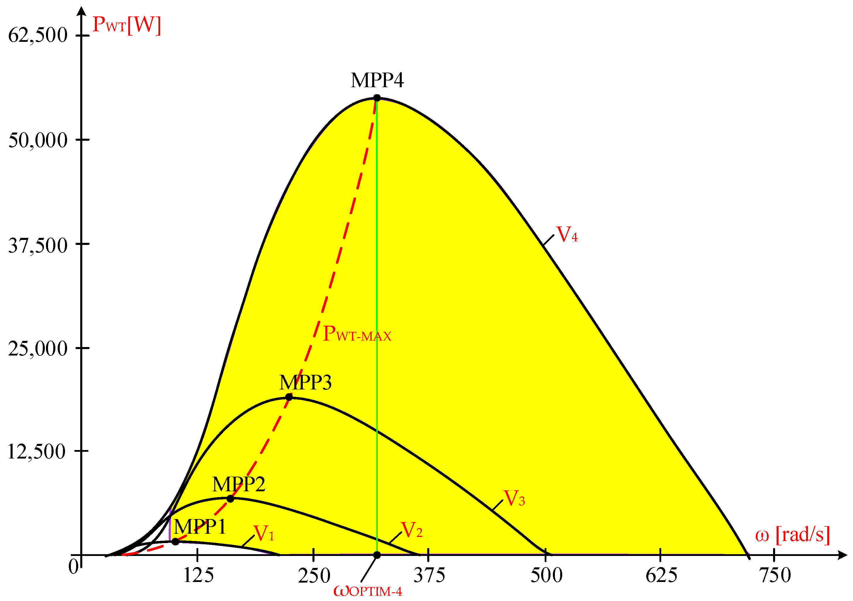
To determine the power characteristics of the turbine and generator, the technical data of a wind system with a capacity of 55 kW were analyzed [34]. Within the wind speed range of 3 m/s to 10 m/s, the wind turbine operates at maximum power points (MPP), as shown in Figure 1.
In this range, the wind speed varies in proportion:
V M I N I M V M A X = 3 10
Consequently, the generator speed must be adjusted within a ratio of 1 to 3.3.
To achieve the highest energy performance in this range of rotational speeds, adjustments are made to the voltage and frequency at the generator using power converters in the following configurations [35,36]:
  • Connection to the stator, in the case of induction generators with a short-circuited rotor.
  • Connection to the rotor, in the case of induction generators with a wound rotor.
Induction generators with a wound rotor can use two converters: one for the stator winding and another for the rotor winding [37]. Connection to the stator, in the case of induction generators with a short-circuited rotor. This configuration allows direct control of the stator frequency and voltage, enabling effective regulation of the generator speed and simplified control architecture. However, it requires a power converter rated for the full generator power.
From a practical and control perspective, the choice between stator-side and rotor-side converter configurations involves distinct trade-offs. Rotor-side converter solutions (e.g., in wound-rotor induction generators) enable reduced converter ratings and improved efficiency, but require more complex machine construction, including slip rings and associated maintenance. In contrast, stator-side converter configurations, as considered in this study, provide direct control of stator voltage and frequency, resulting in a simpler control structure and a clearer relationship between electrical control variables and the operating point of the system, at the expense of requiring a full-rated converter.
In the analyzed case, due to the significant variation in wind speed (3–10 m/s), the generator rotational speed must be adjusted over a wide range, which necessitates the use of a power electronic converter, either on the stator or rotor side, in order to maintain operation near the maximum power point. The stator-side configuration is adopted in this work because it enables a more direct and physically interpretable analysis of the relationship between stator frequency, operating point selection, and system stability, which is the main focus of the study.
In ref. [34], the analysis provided a detailed examination of induction generators with a wound rotor, using a power converter in the rotor circuit to achieve turbine operation at the maximum power point. Under this condition, the voltage at the slip rings exceeds twice the nominal stator voltage when the wind speed reaches 10 m/s. Consequently, the rotor, which has a special design, is more expensive than the conventional variant.
The power of the turbine at wind speed V depends on the mechanical angular speed ω and the blade pitch angle β of the turbine blades. At wind speeds above 10 m/s, the blade pitch angle is adjusted to maintain the structural integrity of the wind system. The shaft power generated by a three-blade wind turbine is calculated using the following relationship:
P W T ω , V , β = ρ π R p 2 C p λ , β V 3
where ρ represents the air density at the operational site of the wind turbine (WT), Rp denotes the radius of the turbine rotor, and Cp(λ, β) is the power conversion coefficient (where λ = ω · Rp/V). The power conversion coefficient Cp(λ, β) for a wind turbine with three blades and a blade pitch angle β is determined using the following relationship:
C p λ , β = c 1 c 2 Λ c 3 e c 4 Λ
where c1, c2, c3, and c4 are constructive constants provided in the turbine catalogue and d is a factor that accounts for the rotational effects of the turbine blades:
1 Λ = 1 λ exp d β 0.035 = V R p ω exp d β 0.035
By substituting Λ, the power conversion coefficient is obtained as follows:
C p λ = c 1 c 2 V R p ω exp d β 0.035 c 3 e x p c 4 V 1.5 ω 0.035 = a V R p ω exp d β b exp c V ω
By substituting the expression of the power coefficient Cp(λ, β) given in Equation (5) into the aerodynamic power Equation (2), the wind turbine power is obtained in the form:
P W T ω , V , β = a V ω exp d β cos π 180 β c exp d V ω V 3
The values of the parameters a, b, c, and d are derived from experimental data reported in the literature for a 55 kW wind turbine [34,38]. These parameters were identified by fitting analytical expressions to the experimentally obtained turbine power curves, ensuring an accurate representation of the power–speed characteristics used in this study. For the analyzed case, the parameter values are a = 19,182, b = 1.3877·10−2, c = 57.65 and d = 0.
Equation (7) is obtained from Equation (6) by rearranging the terms and expressing the turbine power as a function of the wind speed V and the mechanical angular speed ω:
P W T ω , V = 19,182 V ω 1.3877 10 2 exp 57.65 V ω V 3
This relationship highlights that turbine power is governed by the interplay between wind speed and rotational speed, reflecting the underlying aerodynamic conversion process and explaining why a specific angular speed optimizes energy extraction for each wind condition. In the following, ω denotes the mechanical angular speed of the generator shaft (high-speed shaft), unless explicitly stated otherwise.
The technical data from a 55 kW wind turbine [38], equipped with an induction generator featuring a short-circuited rotor, have been processed. The power characteristics of the turbine at four wind speeds, V1 = 3 m/s, V2 = 5 m/s, V3 = 7 m/s, and V4 = 10 m/s, are as follows:
P W T 1 ω , 3 = 19,182 3 ω 1.3877 10 2 exp 57.65 3 ω 3 3
P W T 2 ω , 5 = 19,182 5 ω 1.3877 10 2 exp 57.65 5 ω 5 3
P W T 3 ω , 7 = 19,182 7 ω 1.3877 10 2 exp 57.65 7 ω 7 3
P W T 4 ω , 10 = 19,182 10 ω 1.3877 10 2 exp 57.65 10 ω 10 3
The key characteristic of the maximum power generated by the PWT-MAX turbine, obtained through analytical fitting of experimental data, is expressed as:
P W T M A X ω = 1.6744 10 3 ω 3
is presented in Figure 1. The EG power depends on the stator voltage, U (for the nominal voltage UN = 230 V and frequency f = 50 Hz), as well as the mechanical angular speed ω, exhibiting a power characteristic of the form [34]:
P E G ω = 3 230 2 3.8179 10 2 1 3.1847 10 3 ω 3.8179 10 2 + 3.8179 10 2 1 3.1847 10 3 ω 2 + 1.31 2
This formulation shows that the generator power is directly influenced by the stator electrical quantities, particularly the frequency, which acts as a control variable and determines the electromechanical energy conversion process, thereby defining the system operating point.
Since the wind system operates over a wide range of rotational speeds, it requires variable voltages and frequencies, without saturating the magnetic core, that is, at nominal stator flux. By maintaining a constant stator flux, based on the converter interposed between the grid and generator, the following result is obtained:
U f 1 = 230 50 = 4.6       [ V / Hz ]
The generator’s power characteristic, PEG, is thus obtained,
P E G ω , f = 3 4.6 2 3.8179 10 2 1 0.15915 f ω 3.8179 10 2 + 3.8179 10 2 1 0.15915 f ω 2 f 2 + 1.31 50 2
depending on the mechanical angular speed ω and the stator frequency f. This expression shows that the generator power depends on both the mechanical angular speed and the stator frequency, indicating that the operating point of the system can be controlled through electrical parameters.
The maximum power characteristic of the turbine, PWT-MAX(ω), intersects the maximum power points (MPP) in Figure 1: MPP1 at wind speed V1 = 3 m/s, MPP2 at wind speed V2 = 5 m/s, MPP3 at wind speed V3 = 7 m/s, and MPP4 at wind speed V4 = 10 m/s.
Variations in wind speed lead to dynamic operation of the wind turbine, with variable speeds at the maximum power point [15]. Considering the dynamic nature of the process, the equation of motion is expressed as follows. The model is developed under simplifying assumptions in order to capture the main dynamic behavior of the system [39,40]:
J d ω d t = M W T M E G
where ω represents the mechanical angular speed at the generator shaft (high-speed shaft), after the gearbox, MAS, at the EG shaft; J denotes the equivalent moment of inertia; and dω/dt signifies the time derivative of MAS. MWT refers to the moment provided by the WT, as it relates to the shaft of the EG, and MEG indicates the electromagnetic moment at the EG shaft. By multiplying by ω, the power equation is derived [41]:
J d ω d t ω = P W T P E G
where PWT denotes the useful power supplied by WT, measured at the EG shaft, while PEG denotes the electromagnetic power at the EG shaft. The wind system operates at the intersection of the electric generator, PEG(ω), and wind turbine, PWT(ω), power characteristics. This equation represents the dynamic balance between the mechanical power provided by the turbine and the electromagnetic power of the generator, determining the variation in the rotational speed over time.
From a local stability perspective, the operating point can be evaluated using a derivative-based condition derived from the motion Equation (17). Stability requires that small deviations in mechanical angular speed produce restoring behavior, which can be expressed as:
d P W T P E G d ω < 0
evaluated at the equilibrium point.
This condition ensures that an increase in ω leads to a decrease in the net accelerating power, driving the system back to equilibrium. Conversely, if the derivative is positive, the operating point becomes unstable.
From a physical perspective, this condition indicates that system stability depends on the balance between the mechanical power provided by the turbine and the electrical power absorbed by the generator. A stable operating point is achieved when deviations in rotational speed generate a restoring effect, driving the system back toward equilibrium. When the wind turbine (WT) captures maximum wind energy, it operates at maximum power points (MPP) [42]. To achieve this, the electric generator power characteristic (PEG) must align with the maximum power characteristic produced by the turbine, as shown in Figure 1. The power extracted from the stator, through the power converter located between the generator and the grid, influences the power characteristic of the electric generator (PEG).
The validity of the proposed analytical framework is supported by the consistency between the different analysis methods employed, including analytical modeling, graphical interpretation of power characteristics, and dynamic simulation results. This combined approach allows cross-verification of the system behavior and provides a coherent description of the stability of the operating point.

3. Functionality of the System in the Optimal Zone

Due to the continuous variation in wind speed, enabling the turbine to operate at maximum power points (MPP), as shown in Figure 1, requires adjusting the generator’s rotational speed of the generator by changing the frequency and stator voltage.
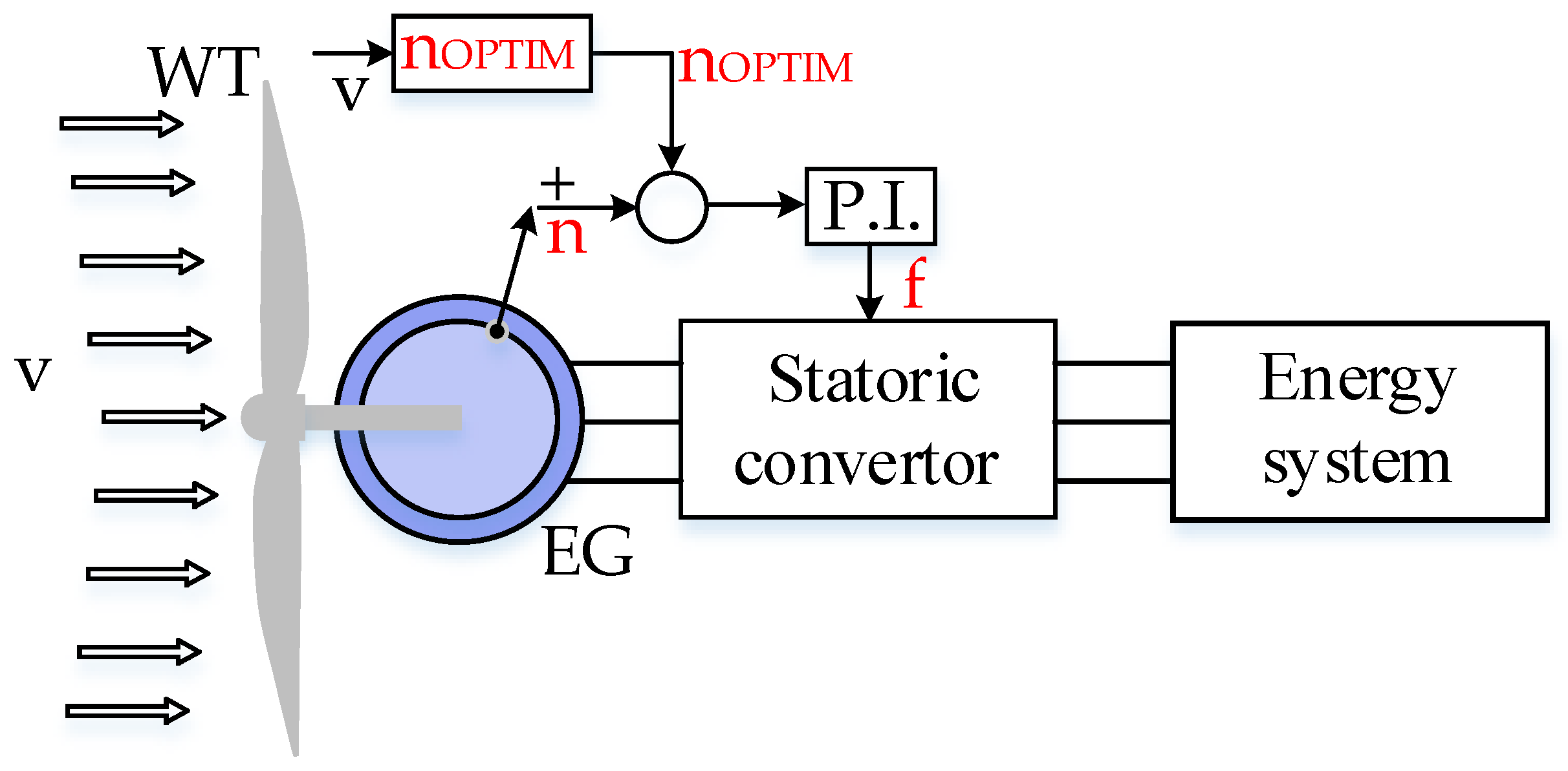
The adjustment of stator voltage and frequency is accomplished using a converter placed between the grid and the generator, as shown in Figure 2 [34].
The power of the induction generator is derived from the steady-state model of the induction machine, where the electromagnetic power is expressed as a function of slip and stator voltage. In the present analysis, a simplified analytical formulation is used, in which the machine parameters (such as inductances and resistances) are incorporated into the coefficients of the expressions:
P E G s , U S = 3 U S 2 R R s R S + R R s 2 + 1.31 2
depends on the slip s and the square of the voltage US2.
Since the voltage-to-frequency ratio remains constant, voltage can be replaced with frequency f. By substituting slip s with mechanical angular speed ω and frequency f:
s = 1 0.15915 f ω
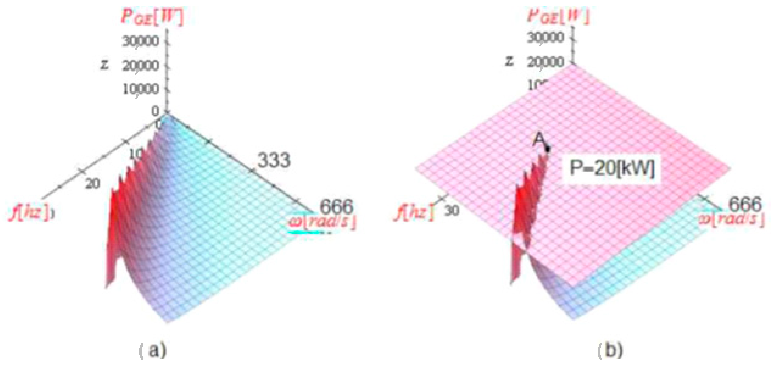
the power of the induction generator, PEG(ω, f), is obtained as a function of two variables: ω and f, as illustrated in Figure 3.
P E G ω , f = 3 4.6 2 3.8179 10 2 1 0.15915 f ω 3.8179 10 2 + 3.8179 10 2 1 0.15915 f ω f 2 2 + 1.31 50 2
This formulation makes it possible to analyze how variations in stator frequency influence the generator power and consequently the system operating point.
In Figure 3, the power characteristics are shown for frequency intervals of 0–50 Hz and mechanical angular speed ranging from 0 to 333 rad/s. These power characteristics are particularly useful for visually estimating the power reserve at a specified induction generator power value.
For an induction generator power rating of P = 20 kW, as shown in Figure 3b, it is observed that the power reserve increases with increasing frequency and decreases with decreasing frequency, ultimately becoming negative at low frequencies. This value is selected as a representative operating point within the operating range of the 55 kW reference wind turbine, allowing a clearer analysis of power characteristics and stability behavior under varying operating conditions.
Among the power characteristics, PEG(ω, f) reveals the power reserves. Thus, considering an induction generator power value of P*EG(ω, f) = 20 kW, or:
20,000 = 3 4.6 2 3.8179 10 2 1 0.15915 f ω 3.8179 10 2 + 3.8179 10 2 1 0.15915 f ω 2 f 2 + 1.31 50 2
The critical operating point A (Figure 3b) is defined by the coordinates f* = 15 Hz and ω* = 103.1 rad/s, as determined from the power equation:
20,000 = 3 4.6 2 3.8179 10 2 1 0.15915 f ω 3.8179 10 2 + 3.8179 10 2 1 0.15915 f ω 2 f 2 + 1.31 50 2 f = 15
The system’s operational area, at a generator power of 20 kW, is feasible only when the frequency exceeds 15 Hz, and the power reserve increases as the frequency rises:
Δ P E G R E S E R V E = Δ P E G M A X I M 20,000
By adjusting the frequency, f, and the stator voltage, the optimal mechanical angular speed, ωOPTIM, is achieved according to the wind speed, as shown in Figure 1. At constant stator flux (10), the generator power in steady state equals that of the turbine (2):
19,182 V ω 1.3877 10 2 e 57.65 V ω V 3 = 3 4.6 2 3.8179 10 2 1 0.15915 f ω 3.8179 10 2 + 3.8179 10 2 1 0.15915 f ω 2 f 2 + 1.31 50 2
Given the negligible inertia of the converter between the generator and the grid, compared to the turbine’s mechanical inertia, the stator frequency, f, is reached without delay. Under maximum power point (MPP) conditions, the mechanical angular speed follows the relation ωopt = k·V. Therefore, the stator frequency, f, is adjusted to enable the wind turbine (WT) to operate at the maximum power point, continuously maintaining the optimal mechanical angular speed:
ω O P T I M = 32.026 V
depending on the wind speed, V. In steady-state operation, the powers are equivalent, meaning PWT(ω, V) = PEG(ω, f).

4. Stability Issues in System Control Through the Enforcement of Optimal RPM

This section investigates the stability of the wind energy system when operating at or near the maximum power point under varying wind conditions. The analysis focuses on how the selection of stator frequency influences the stability of the operating point.
A combined analytical and graphical approach is employed. It is based on:
  • The comparison between turbine and generator power characteristics;
  • The dynamic behavior derived from the motion equation.
This approach allows identifying stable and unstable operating regions and provides a clear physical interpretation of system behavior under small disturbances in wind speed.
The stator frequency and voltage must be closely coordinated with the wind speed, as they directly influence the position and stability of the operating point. A fluctuation in wind speed is considered as follows:
V t = 6 + 2 sin 2 π 666 t = 6 + 2 sin 9.43 10 3 t
This variation is used to evaluate the system response to small disturbances, which is essential for determining the stability of the operating point. The optimal mechanical angular speed is as follows:
ω O P T I M t = 32.026 6 + 2 sin 2 π 666 t = 6 + 2 sin 9.43 10 3 t
The stability analysis presented in this section is based on a combined analytical and graphical approach, supported by the dynamic equations of motion of the system. This approach allows a physically intuitive interpretation of stability by analyzing the interaction between turbine and generator power characteristics under varying wind conditions.
The process is visualized by solving the motion Equation (12), where the system’s total moment of inertia, comprising the turbine and generator, is J = 0.7 kg·m2, leading to the motion equation:
0.7 d ω d t ω = P W T P E G
Consequently, a system of differential equations arises: the equation of motion and the frequency regulator equation.
0.7 d ω d t ω = P W T P E G f f O P T I M = K 1 ω 32.026 6 + 2 sin 9.43 10 3 t + K 2 ω 32.026 6 + 2 sin 9.43 10 3 t d t
At the initial conditions, when t = 0:
P E G ω , f = 3 4.6 2 3.8179 10 2 1 0.15915 f ω 3.8179 10 2 + 3.8179 10 2 1 0.15915 f ω 2 f 2 + 1.31 50 2
The wind speed value of 6 m/s is selected as a representative operating point within the normal operating range of the wind turbine, corresponding to a region where maximum power point operation is relevant.
The stability analysis is performed by considering small variations in wind speed (e.g., from 6 m/s to 6.5 m/s) to evaluate the local stability of the system around the maximum power point.
The same analytical approach can be applied to other wind speed values.
At time t = 0, the generator’s power equals that of the turbine (13), and at a wind speed of V(0) = 6 m/s, it follows that:
19,182 6 ω 1.3877 10 2 exp 57.65 6 ω 6 3 = 3 4.6 2 3.8179 10 2 1 0.15915 f ω 3.8179 10 2 + 3.8179 10 2 1 0.15915 f ω 2 f 2 + 1.31 50 2
It is assumed that the mechanical angular speed ω is equal to the optimal value, ωOPTIM, which is:
ω O P T I M 0 = 32.026 6 = 192.16   [ rad / s ]
According to the equality of powers (20), two values for the optimal frequency are obtained: f1 = 23.695 Hz and f2 = 30.344 Hz.
The characteristics of the generator’s power at the two frequency values, f1 = 23.695 Hz and f2 = 30.344 Hz, are as follows:
P E G 1 ω , 23.695 = 3 4.6 2 3.8179 10 2 1 0.15915 23.695 ω 3.8179 10 2 + 3.8179 10 2 1 0.15915 23.695 ω 2 23.695 2 + 1.31 50 2
P E G 2 ω , 30.344 = 3 4.6 2 3.8179 10 2 1 0.15915 30.344 ω 3.8179 10 2 + 3.8179 10 2 1 0.15915 30.344 ω 2 30.344 2 + 1.31 50 2
The operating point is located at the intersection of the generator power characteristic, PEG, and the turbine power characteristic, PWT. The question arises as to whether the system is stable at both frequency values, f1 and f2.

Stability of the System in Response to Frequency Changes

The turbine’s power characteristic, when V = 6 m/s, is:
P W T 6 ω = 19,182 6 ω 1.3877 10 2 e 57.65 6 ω 6 3
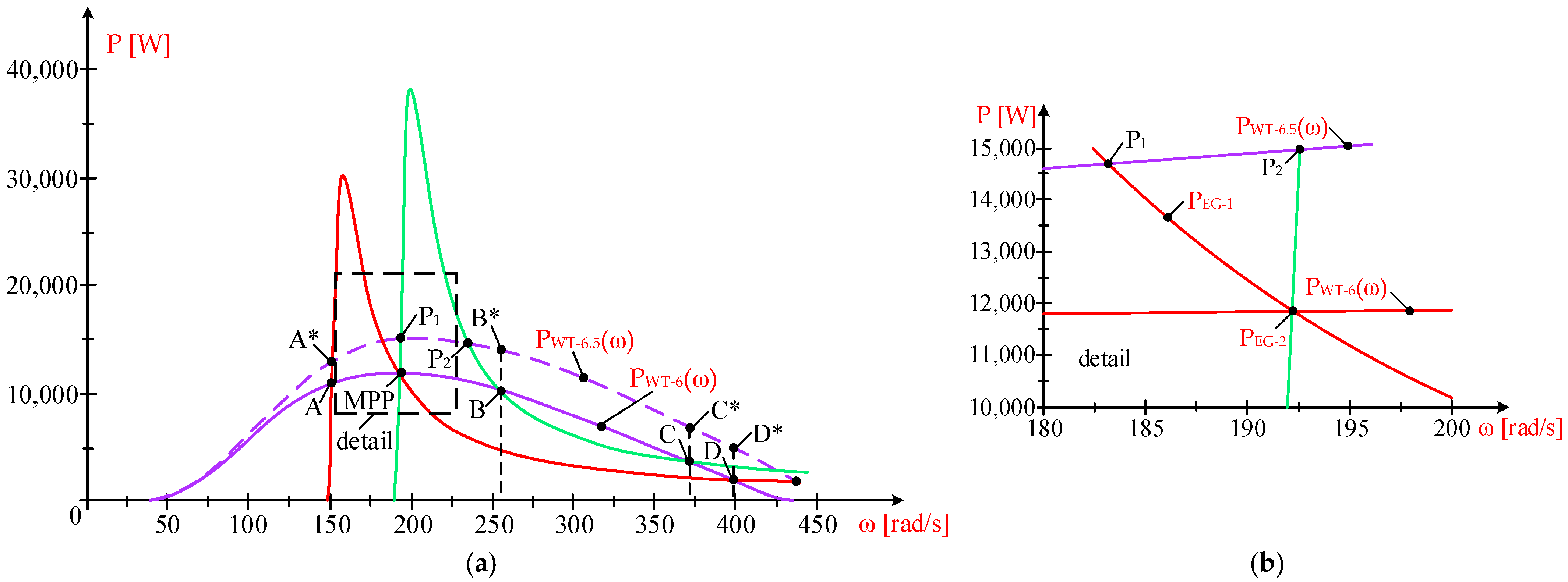
intersections occur with those of the generator, PEG-1 (ω, 23.695) and PEG-2 (ω, 30.344), at points A, MPP, B, C, and D, as shown in Figure 3. The points A, B, C, D, and MPP represent the operating points defined by the intersection of the turbine power characteristic and the generator power characteristics at different stator frequencies. Each point corresponds to a specific operating condition of the system, characterized by a particular mechanical angular speed and power level.
The stability of each operating point is determined by analyzing the relative variation in turbine and generator power with respect to changes in rotational speed. A stable operating point is characterized by the tendency of the system to return to equilibrium after a small disturbance, whereas an unstable point leads to divergence from the initial operating condition.
It is considered that the wind speed increases from 6 m/s to 6.5 m/s, and the initial operating point, MPP, will move in the direction indicated in Figure 4.
The turbine ‘s characteristic when V = 6.5 m/s is as follows:
P W T 6.5 ω = 19,182 6.5 ω 1.3877 10 2 exp 57.65 6.5 ω 6.5 3
Based on this characteristic, the points A, MPP, B, C, and D on the turbine power characteristic at V = 6 m/s will correspond to A*, P1, P2, B*, C*, and D*. When the wind speed changes, the operating point shifts along the corresponding power characteristic, leading to new equilibrium points (e.g., AA*, MPPP2). These transitions illustrate how the system responds dynamically to external disturbances.
A graphical analysis of the power characteristics allows the identification of the nature of the operating points.
The operating points A, B, C, D, and MPP correspond to the intersections between turbine and generator power characteristics at different stator frequencies.
Their stability depends on the response of the system to small perturbations in rotational speed. Points A, C, and D represent stable equilibrium conditions, where deviations lead to restoring behavior, whereas point B corresponds to an unstable equilibrium, where perturbations cause divergence from the operating point.
This analysis confirms that multiple operating points may exist under the same wind conditions, but their stability properties differ significantly. An important observation is that, for a given wind speed, multiple stator frequency values may satisfy the steady-state power balance condition. However, only one of these frequencies ensures the stable operation of the system.
This result can be further interpreted from a control-theoretic perspective. For a given wind speed, the steady-state condition may admit multiple equilibrium solutions corresponding to different stator frequency values (e.g., f1 and f2). However, the stability analysis—performed both mathematically, using the motion equation, and graphically, using the power characteristics—shows that only one of these solutions ensures stable operation under small wind perturbations.
This demonstrates that satisfying the steady-state power balance alone is not sufficient to guarantee stability, and that the selection of the operating frequency must explicitly account for stability constraints. This aspect highlights a non-trivial characteristic of the control problem and represents a key contribution of the present study.
Consequently, the operating point must be selected not only based on power matching but also considering stability constraints, which represent a critical limitation of conventional MPPT approaches that assume a unique optimal operating condition.
The stability of the system can be analyzed at the two frequency values, f1 and f2, by utilizing the power equation:
J d ω d t ω = P W T P E G
or the motion equation at f1 = 23.695 Hz:
0.7 d ω d t ω = 19,182 6.5 ω 1.3877 10 2 exp 57.65 6.5 ω 6.5 3 + 3 4.6 2 3.8179 10 2 1 0.15915 23.695 ω 3.8179 10 2 + 3.8179 10 2 1 0.15915 23.695 ω 2 23.695 2 + 1.31 50 2
for the mechanical angular speed ω at f1, ω(0) = 192.16, and the equation of motion at f2 = 30.344 Hz
0.7 d Ω d t Ω = 19,182 6.5 Ω 1.3877 10 2 exp 57.65 6.5 Ω 6.5 3 + 3 4.6 2 3.8179 10 2 1 0.15915 30.344 Ω 3.8179 10 2 + 3.8179 10 2 1 0.15915 30.344 Ω 2 30.344 2 + 1.31 50 2
For the mechanical angular speed Ω at f2, Ω(0) = 192.16.
Thus, the following system of differential equations was obtained:
0.7 d ω d t ω = 19,182 6.5 ω 1.3877 10 2 exp 57.65 6.5 ω 6.5 3 + 3 4.6 2 3.8179 10 2 1 0.15915 23.695 ω 3.8179 10 2 + 3.8179 10 2 1 0.15915 23.695 ω 2 23.695 2 + 1.31 50 2 0.7 d Ω d t Ω = 19,182 6.5 Ω 1.3877 10 2 exp 57.65 6.5 Ω 6.5 3 + 3 4.6 2 3.8179 10 2 1 0.15915 30.344 Ω 3.8179 10 2 + 3.8179 10 2 1 0.15915 30.344 Ω 2 30.344 2 + 1.31 50 2 ω 0   =   192.16 Ω 0   =   192.16
By solving this system, one can determine the changes in mechanical angular speed over time and draw conclusions regarding the stability of the system, as discussed below. By increasing the wind speed from 6 m/s to 6.5 m/s, the initial operating point, with ω(0) = 192.16 rad/s, shifts along the generator’s power characteristic:
P E G 1 ω , 23.695 = 3 4.6 2 3.8179 10 2 1 0.15915 23.695 ω 3.8179 10 2 + 3.8179 10 2 1 0.15915 23.695 ω 2 23.695 2 + 1.31 50 2
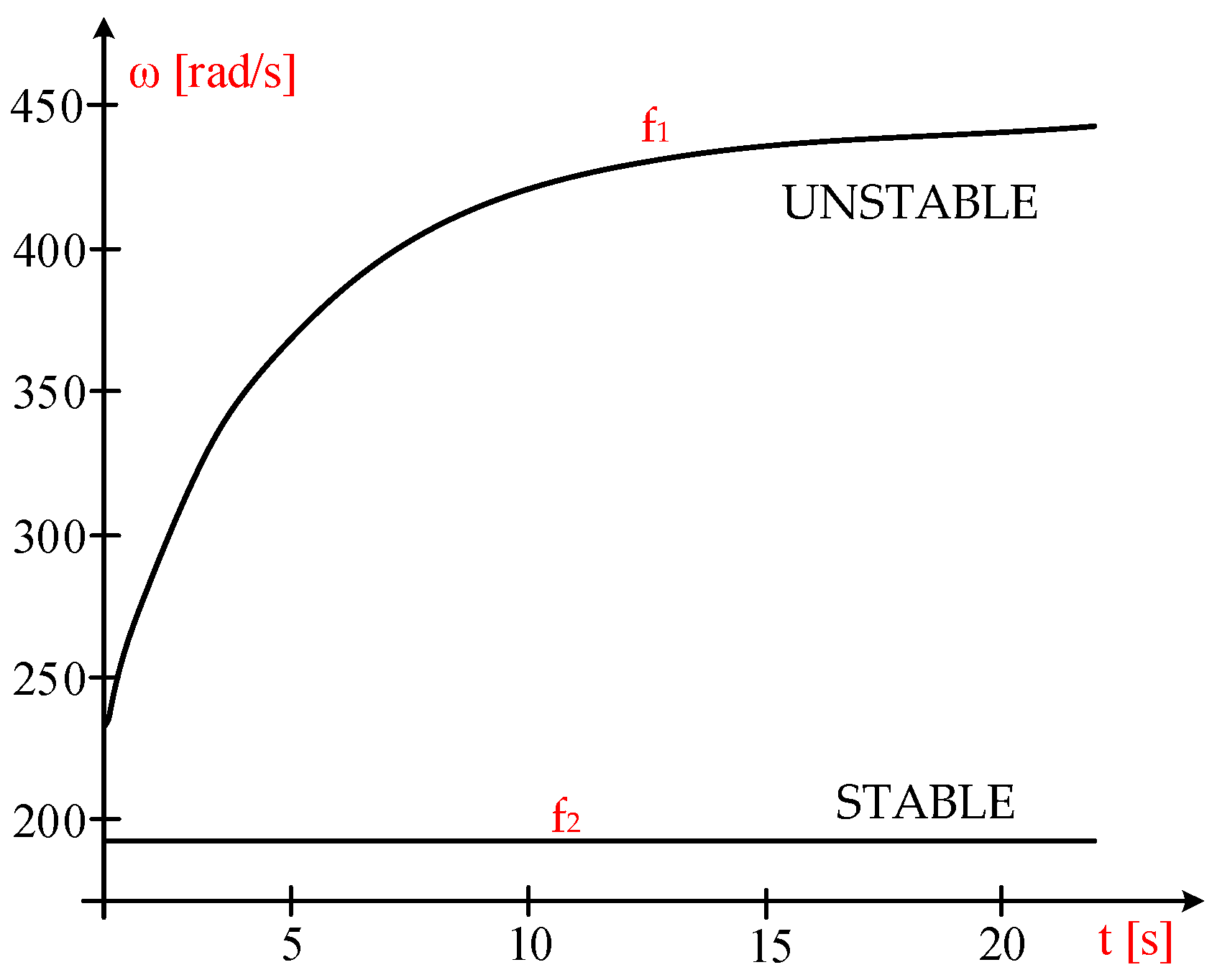
At f1 = 23.695 Hz, after 44 s, the mechanical angular speed is:
ω 44 = 443.19   rad / s   > >   ω 0 = 192.16   rad / s
Given that the initial and final values of the mechanical angular speed differ significantly, it follows that at f1 = 23.695 Hz the system is unstable, as illustrated in Figure 4.
Similarly, by increasing the wind speed from 6 m/s to 6.5 m/s, the initial operating point shifts along the generator’s power characteristic:
P E G 2 ω , 30.344 = 3 4.6 2 3.8179 10 2 1 0.15915 30.344 ω 3.8179 10 2 + 3.8179 10 2 1 0.15915 30.344 ω 2 30.344 2 + 1.31 50 2
At frequency f2 = 30.344 Hz, after 66 s, the mechanical angular speed is measured at Ω(66) = 192.57 rad/s, which is close to the initial value of Ω(0) =192.16 rad/s.
The initial and final values of the mechanical angular speed are very similar, indicating that at f2 = 30.344 Hz the system is stable, as shown in Figure 5.
From Figure 5, it is clear that at frequency f1, the MAS increases from the initial value of ω(0) = 192.16 rad/s to ω(48) = 443.2 rad/s after approximately 48 s. This indicates that the operation is unstable at the MPP point, which is also observable in the detailed view of Figure 4, where the operating point has shifted to D, significantly distant from the initial operating point.
From the initial MPP operating point at f2 =30.344 Hz, by increasing the wind speed to 6.5 m/s, the system stabilizes at the operating point P2 (Figure 3—detail), at Ω(11) = 192.57. This is also validated by the equation of motion, of the form:
0.7 d Ω d t Ω = 19,182 6.5 Ω 1.3877 10 2 exp 57.65 6.5 Ω 6.5 3 + 3 4.6 2 3.8179 10 2 1 0.15915 30.344 Ω 3.8179 10 2 + 3.8179 10 2 1 0.15915 30.344 Ω 2 30.344 2 + 1.31 50 2 Ω ( 0 ) = 192.16
In conclusion, the combined graphical and dynamic analysis demonstrates that system stability is strongly dependent on stator frequency selection. Although multiple operating points may satisfy the steady-state power balance, only specific frequency values ensure stable operation under wind disturbances.
This analysis provides a physically meaningful interpretation of stability and emphasizes that the existence of stable and unstable operating regions is strongly dependent on the selected stator frequency, which must be carefully considered when designing control strategies for maximum power point operation.

5. Simulation of System Control Through Frequency Modification

Control of the wind system involves achieving a current mechanical angular speed, ω, equal to the optimal value, ωOPTIM, which is defined as follows:
ω O P T I M = 32.026 V = 32.026 ( 6 + 2 sin 9.43 10 3 t )   [ rad / s ]
for a sinusoidal wind speed fluctuation, in the form:
V t = 6 + 2 sin 2 π 666 t = 6 + 2 sin 9.43 10 3 t
The differential equations of motion and the frequency regulator are as follows:
0.7 d ω d t ω = P W T P E G f f O P T I M = K 1 ω ω O P T I M + K 2 ω ω O P T I M d t
it is obtained:
0.7 d ω d t ω = 19,182 6 + 2 sin 9.43 10 3 t ω 1.3877 10 2 exp 57.65 6 + 2 sin 9.43 10 3 t ω 6 + 2 sin 9.43 10 3 t 3 + 3 4.6 2 3.8179 10 2 1 0.15915 f ω 3.8179 10 2 + 3.8179 10 2 1 0.15915 f Ω 2 f 2 + 1.31 50 2 d f d t = 0.17263 d ω d t 0.60401 cos 0.00943 t 0.28 ω 32.026 6 + 2 sin 9.43 10 3 t ω 0 = 192.16 f 0 = 30.344
Tuning the frequency regulators involves determining the constants K1 for proportionality and K2 for integration.
The PI controller is designed based on an analytical and physically motivated approach, aiming to ensure that the mechanical angular speed follows the optimal value corresponding to the maximum power point.
Proportionality constant, K1. Only the proportional component of the regulator is considered:
f f O P T I M = K 1 ω ω O P T I M
and through derivation, it is obtained:
d f d t = K 1 d ω d t
resulting in:
K 1 = d f d ω Δ f Δ ω
The proportional gain K1 determines the immediate response of the system to deviations between the actual and optimal mechanical angular speed. A higher value of K1 increases the sensitivity of the control action, allowing faster correction of deviation.
Near the initial operating point, MPP, at a wind speed of V(0) = 6 m/s, from the power equality PWT = PEG, the optimal frequency fOPTIM = 30.344 Hz was determined.
The proportionality constant K1 is determined as follows:
A frequency value is selected, f2 = 31 Hz, which is close to the initial frequency f1 = 30.344 Hz, and the following is obtained:
Δ f = f 2 f 1 = 31 30.344 = 0.656   Hz
The power characteristics of the generator at the two frequency values are:
P E G 1 ω = 3 4.6 2 3.8179 10 2 1 0.15915 30.344 ω 3.8179 10 2 + 3.8179 10 2 1 0.15915 30.344 ω 2 30.344 2 + 1.31 50 2
P E G 2 ω = 3 4.6 2 3.8179 10 2 1 0.15915 31 ω 3.8179 10 2 + 3.8179 10 2 1 0.15915 31 ω 2 31 2 + 1.31 50 2
For a wind speed of 6 m/s, the power characteristic of the turbine is obtained as follows:
P W T 6 ω = 19,182 6 ω 1.3877 10 2 exp 57.65 6 ω 6 3
The intersection points of the power characteristics of the generator, PEG-1(ω) and PEG-2(ω), with that of the turbine, PWT-6(ω), are determined.
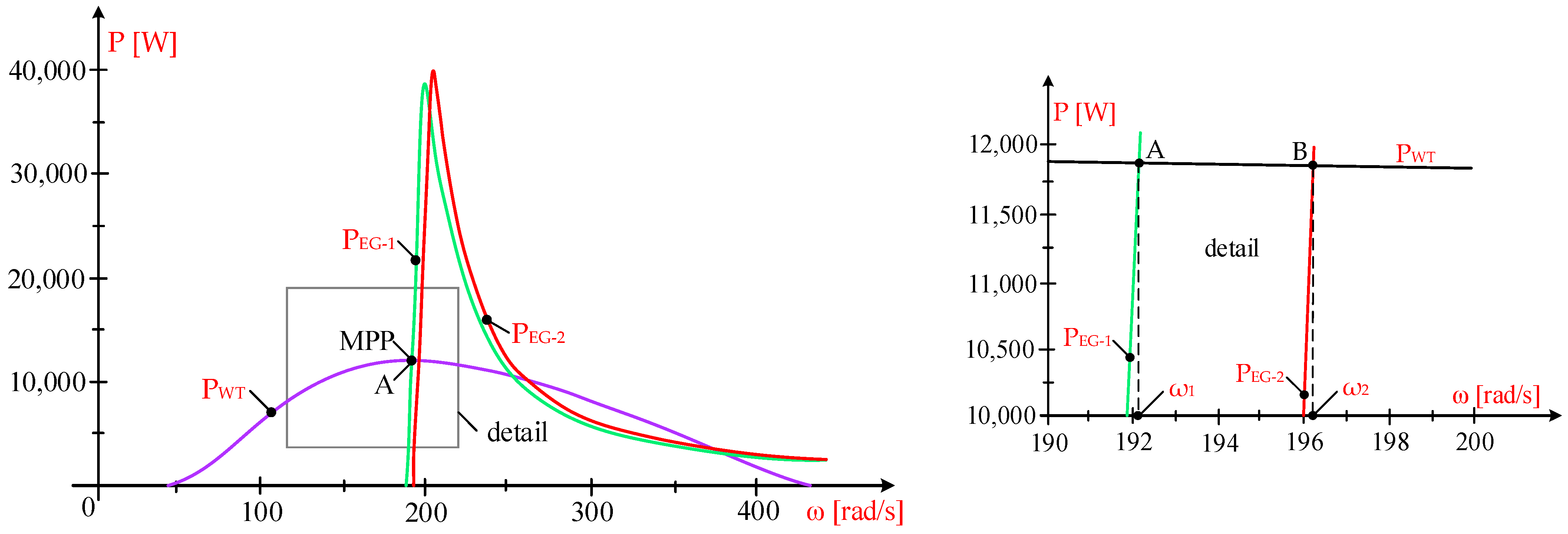
The power characteristics of both the turbine and the generator are shown in Figure 6, where the intersection points, A and B, of the power characteristics of the turbine and generator are also visible.
At the equality of forces, the values of the mechanical angular velocities ω1 for point A and ω2 for point B are obtained:
  • Point A, ω1 = 192.3 rad/s:
19,182 6 ω 1.3877 10 2 exp 57.65 6 ω 6 3 = 3 4.6 2 3.8179 10 2 1 0.15915 30.344 ω 3.8179 10 2 + 3.8179 10 2 1 0.15915 30.344 ω 2 30.344 2 + 1.31 50 2
Point B, ω2 = 196.1 rad/s:
19,182 6 ω 1.3877 10 2 exp 57.65 6 ω 6 3 = 3 4.6 2 3.8179 10 2 1 0.15915 31 ω 3.8179 10 2 + 3.8179 10 2 1 0.15915 31 ω 2 31 2 + 1.31 50 2
The difference Δω between the mechanical angular velocities ω1 and ω2 is:
Δ ω = ω 2 ω 1 = 196.1 192.3 = 3.8   Hz
and the proportionality constant K1 is obtained:
K 1 = d f d ω = 0.656 3.8 = 0.17263
Integration constant, K2. To determine the integration constant K2, only the integration component of the regulator is considered:
f f O P T I M = K 2 ω ω O P T I M d t
and, through derivation, the following is obtained:
d f d t = K 2 ω ω O P T I M
resulting in:
K 2 = d f d t ω ω O P T I M Δ f Δ t ω ω O P T I M
The integral gain K2 ensures the elimination of steady-state error by continuously adjusting the control signal based on the accumulated deviation in mechanical angular speed.
At frequencies f2 = 31 Hz and f1 = 30.344 Hz, the following results were obtained:
Δ f = f 2 f 1 = 31 30.344 = 0.656   Hz
Near the initial operating point, MPP, at a wind speed of V0 = 6 m/s, the optimal MAS is:
ω O P T I M = 32.026 6 = 192.16   rad / s
The time interval is derived from the motion equation:
J d ω d t ω = P W T P E G
or:
J ω d ω = P W T P E G d t
and by integration we obtain:
0.7 ω 2 2 ω 1 2 2 = P W T 6 P E G M E D I U Δ t
resulting in:
Δ t = 0.7 ω 2 2 ω 1 2 2 P W T 6 P E G M E D I U = 0.7 196.1 2 192.3 2 2 P W T P E G M E D I U = 516.57 P W T P E G M E D I U
The power of the turbine, PWT (6), at
ω = ω 2 + ω 1 2 = 196.1 + 192.3 2 = 194.2   Hz
is:
ω = 194.2   Hz P W T = 19,182 6 ω 1.3877 10 2 exp 57.65 6 ω 6 3 = 11,878   W
Generator power at ω1 = 192.3 rad/s and f1 = 30.344 Hz, is:
ω = 192.3   Hz P E G 1 = 3 4.6 2 3.8179 10 2 1 0.15915 30.344 ω 3.8179 10 2 + 3.8179 10 2 1 0.15915 30.344 ω 2 30.344 2 + 1.31 50 2 = 12,953   W
and at ω1 = 196.1 rad/s and f2 = 31 Hz it is:
ω = 196.1   Hz P E G 2 = 3 4.6 2 3.8179 10 2 1 0.15915 31 ω 3.8179 10 2 + 3.8179 10 2 1 0.15915 31 ω 2 31 2 + 1.31 50 2 = 12,953   W
The generator’s average power over the time interval t is the arithmetic mean of the two values, PEG-1 and PEG-2, resulting in:
P E G M E D I U = P E G 1 + P E G 2 2 = 12,953 + 10,712 2 = 11,833   W
thus, the value for the time interval t is:
Δ t = 516.57 P W T P E G M E D I U = 516.57 11,878 11,833 = 11.479   s
Thus, the integration component of the value regulator is obtained:
K 2 = d f d t ω ω O P T I M Δ f Δ t ω ω O P T I M = 0.656 11.479 194.2 192.16 = 0.028   s
With these values, K1 = 0.17263 and K2 = 0.028, the differential equations of motion and the frequency regulator become:
0.7 d ω d t ω = 19,182 6 + 2 sin 9.43 10 3 t ω 1.3877 10 2 exp 57.65 6 + 2 sin 9.43 10 3 t ω 6 + 2 sin 9.43 10 3 t 3 + 3 4.6 2 3.8179 10 2 1 0.15915 f ω 3.8179 10 2 + 3.8179 10 2 1 0.15915 f ω 2 f 2 + 1.31 50 2 d f d t = 0.17263 d ω d t 0.60401 cos 0.00943 t 0.028 ω 32.026 6 + 2 sin 9.43 10 3 t ω 0 = 192.16 f 0 = 30.344
The tuning procedure is based on the dynamic behavior of the system derived from the motion equation, providing a physically consistent approach for selecting the controller parameters within the given operating range.
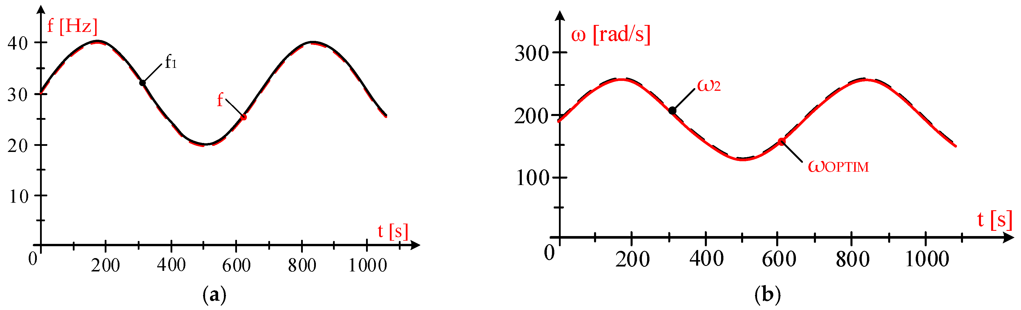
Knowing the dependence of frequency on wind speed as [9,13] f1 = 5 · V gives the model frequency variation, f1:
f 1 = 5 V = 5 6 + 2 sin 9.43 10 3 t   s
By solving the system of differential equations, the variations in the actual frequencies, f (red), and modelled frequencies, f1 (black), as well as the current angular velocities, ω (black), and the optimal angular velocities, ωOPTIM (red), are obtained, as shown in Figure 7a,b.
The same variations in frequency and angular mechanical velocities are also obtained at K1 = 0.1 and K2 = 0.05, using the equations:
0.7 d ω d t ω = 19,182 6 + 2 sin 9.43 10 3 t ω 1.3877 10 2 exp 57.65 6 + 2 sin 9.43 10 3 t ω 6 + 2 sin 9.43 10 3 t 3 + 3 4.6 2 3.8179 10 2 1 0.15915 f ω 3.8179 10 2 + 3.8179 10 2 1 0.15915 f Ω 2 f 2 + 1.31 50 2 d f d t = 0.1 d ω d t 0.60401 cos 0.00943 t 0.05 ω 32.026 6 + 2 sin 9.43 10 3 t ω 0 = 192.16 f 0 = 30.344
Using the values of K1 and K2, the generator’s output power is related to the wind speed and the current mechanical angular speed, ω, as it approaches the optimal MAS, ωOPTIM. The wind energy captured by the turbine reaches its peak, with the regulator adjusting the frequency and stator voltage in close correlation with the wind speed.

6. Results and Discussion

This study investigates the operational behavior of medium-power wind turbines equipped with squirrel-cage induction generators, controlled through stator-side frequency adjustment using a power electronic converter. The analysis covers wind speed variations from 3 m/s to 10 m/s and evaluates system stability under substantial fluctuations in wind conditions. By modifying the stator frequency, the generator’s rotational speed can be regulated to ensure operation at the maximum power point (MPP).

6.1. Simulation Setup

The simulation model is based on a set of nonlinear differential equations describing the wind turbine and induction generator dynamics. The equations are solved numerically using standard integration methods.
Initial conditions are obtained from the steady-state solution of the system by setting the derivatives to zero. The model parameters correspond to the 55 kW reference wind turbine.
The control system is implemented using a PI regulator that adjusts the stator frequency to maintain operation at the maximum power point. Small variations in wind speed are introduced to evaluate system stability.
The system of nonlinear differential equations was solved numerically using a fixed-step fourth-order Runge–Kutta method implemented in a Scientific Workplace environment, based on the MAPLE computational core. The integration time step was selected to ensure numerical stability and accuracy of the results. Convergence of the numerical solution was verified by ensuring consistent system response for sufficiently small time-step variations.
The PI controller parameters were determined analytically based on the system dynamics derived from the motion equation, as described in Section 5. The controller was implemented in a standard PI form within the numerical simulation framework, using these parameters to regulate the mechanical angular speed towards its optimal value.
The values of the controller parameters are summarized in Table 1.
All simulations were performed within this numerical computing environment, enabling consistent evaluation of the system response under varying wind conditions.

6.2. Results

The main findings of the study can be summarized as follows:
  • Stator frequency and voltage adaptation:
  • The stator frequency and voltage were successfully adjusted in response to wind speed variations using the converter installed between the generator and the grid. This adjustment enabled the turbine to track the optimal mechanical speed corresponding to the MPP, as illustrated in Figure 7a.
2.
Stability assessment across operating frequencies:
  • System stability was evaluated at multiple operating frequencies determined by the imposed wind speed. The analysis revealed distinct stable and unstable regions depending on the selected frequency, as demonstrated in Figure 4 and Figure 5.
3.
PI controller parameter identification:
  • The proportional and integral gains of the PI controller were determined based on the relationship between the actual mechanical angular speed ω and the optimal mechanical angular speed ωOPTIM. Their effect is evident in the convergence behavior shown in Figure 7b, which demonstrates how the controller ensures operation near the optimal point.
To provide a clearer overview of the main findings, a summary of the results is presented in Table 2.

6.3. Fundamental Aspects

The results highlight several fundamental aspects relevant to the operation of medium-power wind turbines:
  • Wide wind speed variability requires flexible speed regulation:
Effective adjustment of the generator’s rotational speed is essential for maximizing energy capture across a broad range of wind speeds. This is consistent with the behavior observed in Figure 7, where the mechanical angular speed follows the optimal value.
  • Dual-frequency feasibility, but only one stable solution:
For a given wind speed, two frequency values may satisfy the power and speed requirements. Only one of the possible operating frequencies ensures stable operation, as shown in Figure 5. This distinction is critical for selecting appropriate control parameters.
  • Proportional adjustment of electrical parameters:
Achieving optimal performance requires coordinated variation in stator frequency and voltage in proportion to wind speed, ensuring that the turbine consistently operates near the MPP.

6.4. Discussion

The findings demonstrate that incorporating a power converter in the stator circuit of the induction generator enables effective control of the turbine’s operating point, allowing it to reach maximum power output under varying wind conditions. As shown in Figure 5 and Figure 7, the system maintains stable operation when the stator frequency is properly adjusted.
The results indicate that the selection of the operating frequency must account not only for maximum power extraction but also for stability constraints. For a given wind speed, the steady-state condition may admit multiple operating solutions, while only one ensures stable behavior under wind perturbations.
In practical implementations, this implies that control strategies must be designed to avoid operating regions that, although satisfying steady-state conditions, may lead to unstable behavior under wind disturbances. This is particularly relevant for converter-based wind energy systems, where the control variables directly influence the operating point of the turbine-generator set. The analysis highlights the importance of correct frequency selection under stability constraints, as illustrated in Figure 5, where different operating regimes (stable and unstable) can be clearly identified.
The analysis was conducted using the technical specifications of a 55 kW wind turbine, providing realistic insights into the behavior of medium-scale systems. This choice supports the practical relevance of the obtained results. The study focuses on a wind energy system employing a squirrel-cage induction generator, which inherently offers fewer speed-control options compared to wound-rotor induction generators or permanent-magnet machines. Despite these limitations, the proposed control strategy—based on stator frequency adjustment and PI-based speed tracking—proves effective in maintaining stable operation and ensuring that the turbine operates close to its optimal power point.
Compared to conventional MPPT strategies typically based on torque control or rotor-side power converters, the proposed approach emphasizes the role of stator-side frequency control and its impact on system stability. This allows not only tracking of the maximum power point but also explicit identification of stable and unstable operating regimes, which represents an important contribution to the analysis of induction generator-based wind systems. While many existing strategies prioritize energy maximization, the present study emphasizes the identification of stable and unstable operating regions, providing additional insight into system behavior.
The proposed approach is developed within an analytical framework that emphasizes the relationship between turbine aerodynamics, generator characteristics, and control through stator frequency adjustment. While the present study is primarily based on analytical modeling and simulation, it provides a structured foundation for understanding the stability behavior of wind energy systems operating at maximum power point.
While the present study is primarily based on analytical modeling and simulation, it provides a structured foundation for understanding the stability behavior of wind energy systems operating at maximum power point. In comparison with conventional MPPT strategies reported in the literature, such as classical PI-based control, torque control methods, and more advanced approaches including adaptive control and intelligent techniques (e.g., fuzzy logic and neural networks), the proposed approach focuses explicitly on the stability of the operating point.
While many existing methods primarily aim to maximize energy capture, often assuming a unique optimal operating condition, the present study demonstrates that multiple steady-state solutions may exist for a given wind speed, with different stability properties. This highlights the importance of incorporating stability considerations into control design, beyond mere power optimization.
Therefore, the main contribution of this work lies in the identification and analysis of stability constraints associated with stator-frequency-based control, providing a complementary perspective to existing MPPT strategies.
In addition, the obtained results are consistent with previously reported studies on induction generator-based wind energy systems operating under variable wind conditions. In particular, the identified behavior—namely the existence of multiple operating points for a given wind speed and their different stability properties—aligns with established theoretical and modeling results reported in the literature.
Furthermore, the observed relationship between stator frequency, rotational speed, and power characteristics is in agreement with classical models used in maximum power point tracking (MPPT) strategies. This consistency provides an indirect validation of the proposed analytical framework, supporting its physical relevance and correctness despite the absence of direct experimental data.

7. Conclusions

This paper analyzed the stability of medium-power wind turbines equipped with squirrel-cage induction generators, regulated through stator-side frequency control using a power electronic converter. The study focused on turbine behavior under significant wind speed variations and demonstrated that the proposed control strategy enables operation over a wide range of rotational speeds. Implementing this approach requires a power converter sized to match the generator’s rated power, ensuring effective adjustment of electrical parameters.
To maintain operation at the maximum power point, a dedicated PI controller was designed and implemented. By modifying the stator frequency, the controller adjusts the available power reserve of the turbine. The results show that when the operating frequency is reduced, the turbine’s aerodynamic power can exceed the generator’s electrical capability, causing the rotational speed to rise beyond acceptable limits. This highlights the importance of selecting appropriate frequency values to ensure both optimal energy capture and stable system operation.
Overall, the findings confirm that stator frequency-based control, combined with a properly tuned PI regulator, provides an effective method for maximizing power extraction while preserving the stability of medium-power wind turbines equipped with squirrel-cage induction generators.
The analysis reveals that, for a given wind speed and maximum power operating condition, the power balance equation may admit multiple stator frequency solutions. However, only one of these solutions ensures local stability of the operating point; in the analyzed case, this corresponds to the higher stator frequency, while the lower frequency leads to instability under small wind variations. This result highlights the importance of considering stability constraints in addition to maximum power extraction when selecting the operating frequency.
The results provide additional insight into the stability-oriented analysis of stator-side frequency control, showing that, although multiple operating conditions may satisfy the power balance, only specific stator frequency values ensure stable operation. This demonstrates that the stability constraints play a critical role in selecting the operating frequency when designing control strategies for induction generator-based wind energy systems.
Future work will focus on extending the proposed approach by incorporating more advanced stability analysis methods, such as small-signal modeling, eigenvalue analysis, and Lyapunov-based techniques, to provide a more rigorous theoretical validation of system behavior. In addition, experimental or hardware-in-the-loop validation will be considered to further confirm the applicability and robustness of the proposed approach under real operating conditions. Further developments will also address the integration of advanced control design strategies, including optimization-based tuning, model-based approaches, and comparative evaluations with conventional methods, with the aim of enhancing system performance, robustness, and practical applicability.

Author Contributions

Conceptualization, C.P.C. and E.S.; methodology, C.P.C.; software, C.P.C. and G.-O.T.; validation, C.P.C., E.S. and G.-O.T.; formal analysis, E.S.; investigation, C.P.C. and G.-O.T.; resources, E.S.; data curation, C.P.C. and G.-O.T.; writing—original draft preparation, C.P.C. and G.-O.T.; writing—review and editing, E.S.; visualization, G.-O.T. and E.S.; supervision, C.P.C.; project ad-ministration, C.P.C. and E.S.; funding acquisition, C.P.C., E.S. and G.-O.T. All authors have read and agreed to the published version of the manuscript.

Funding

The publication of this article was supported by the 2026 Development Fund of the UBB

Institutional Review Board Statement

Not applicable.

Informed Consent Statement

Not applicable.

Data Availability Statement

The original contributions presented in the study are included in the article; further inquiries can be directed to the first author.

Conflicts of Interest

The authors declare no conflicts of interest. The funders had no role in the design of the study; in the collection, analyses, or interpretation of data; in the writing of the manuscript; or in the decision to publish the results.

Abbreviations

The following abbreviations are used in this manuscript:
EUEuropean Union
PIDProportional, Integrator, Derivative
MASMechanical angular speed
WTWind turbine
VWind speed
PVPhotovoltaic
MPPMaximum power point
MPPTMaximum power point tracking
PIProportional, Integrator controller
ωMechanical angular speed
ωOPTIMOptimal mechanical angular speed
PWTPower given by WT relative to the shaft of the electric generator
EGElectric generator
PEGPower of the electric generator
UStator voltage
UNNominal voltage
fStator voltage frequency
JEquivalent inertia moment
MWTMoment provided by WT, relative to the EG shaft
MEGElectromagnetic moment at the EG shaft
tTime moment
K1Proportionality constant
K2Integration constant
A, B, C, D, A*, B*, C*, D*, P1, P2, P3Operating points
βAngle of the turbine blades’ inclination
ρAir density at the operational site of the wind turbine
RpRadius of the turbine rotor
Cp(λ, β)Power conversion coefficient
c1, c2, c3, c4Constructive constants of the wind turbine

References

  1. Electricity from Renewable Sources Reaches 47% in 2024. Available online: https://energyworld.ro/2025/03/21/electricity-from-renewable-sources-reaches-47-in-2024/ (accessed on 11 August 2025).
  2. Jamii, J.; Mimouni, F. Model of wind turbine-pumped storage hydro plant. In Proceedings of the 9th International Renewable Energy Congress (IREC), Hammamet, Tunisia, 20–22 March 2018. [Google Scholar]
  3. Ye, H.; Ding, Y.; Xiao, L.; Li, Q.; Zheng, C.; Wang, Y. Hydro-Tower Pumped Storage-based Wind Power Generator: Short-term Dynamics and Controls. In Proceedings of the 2nd Asian Conference on Frontiers of Power and Energy (ACFPE), Chengdu, China, 20–22 October 2023. [Google Scholar]
  4. Bahadur, S.P.; Shelly, V. An Innovative Continuous Power Generation System Comprising Wind Energy Along With Pumped-Hydro Storage and Open Well. IEEE Trans. Sustain. Energy 2020, 11, 145–153. [Google Scholar]
  5. Moukam, T.D.T.; Sugawara, A.; Li, Y.C.; Bello, Y. An Evaluation of the Power System Stability for a Hybrid Power Plant Using Wind Speed and Cloud Distribution Forecasts. Energies 2025, 18, 1540. [Google Scholar] [CrossRef] [Scilit]
  6. Goyal, S.; Maurya, S.K.; Kumar, S.; Agarwal, D. A Consolidation Review of Major Wind Turbine Models in Global Market. In Proceedings of the International Conference on Power Electronics & IoT Applications in Renewable Energy and Its Control (PARC), Mathura, India, 28–29 February 2020. [Google Scholar]
  7. Najih, Y.; Adar, M.; Aboulouard, A.; Khaouch, Z.; Bengourram, M.; Zekraoui, M. Mechatronic Control Model of a Novel Variable Speed Wind Turbine Concept with Power Splitting Drive Train: A Bond Graph Approach. In Proceedings of the IEEE 6th International Conference on Optimization and Applications (ICOA), Beni Mellal, Morocco, 20–21 April 2020. [Google Scholar]
  8. Naqash, T.M.; Alam, M.M. A State-of-the-Art Review of Wind Turbine Blades: Principles, Flow-Induced Vibrations, Failure, Maintenance, and Vibration Suppression Techniques. Energies 2025, 18, 3319. [Google Scholar] [CrossRef] [Scilit]
  9. Li, T.; Zhang, Y.; Yang, Q.; Zhou, X.; Zhang, Z.; Wang, T. Unsteady aerodynamic characteristics of a floating offshore wind turbine inpropeller state. Renew. Energy 2025, 246, 122861. [Google Scholar]
  10. Zhu, J.Y.; Zhang, L.; Qu, Q.L.; Liu, P.Q. Experimental Investigation of Aerodynamic Characteristics for Three Typical Micro Wind Turbines at Low Reynolds Number. J. Appl. Fluid Mech. 2020, 13, 1143–1148. [Google Scholar] [CrossRef] [Scilit]
  11. Sorandaru, C.; Ancuti, M.-C.; Musuroi, S.; Svoboda, M.; Muller, V.; Erdodi, M.G. Fundamental Issue for Wind Power Systems Operating at Variable Wind Speeds: The Dependence of the Optimal Angular Speed on the Wind Speed. In Proceedings of the 2022 International Conference and Exposition on Electrical and Power Engineering (EPE), Iasi, Romania, 20–22 October 2022. [Google Scholar]
  12. Sorandaru, C.; Musuroi, S.; Frigura-Iliasa, F.M.; Vatau, D.; Dordescu, M. Analysis of the Wind System Operation in the Optimal Energetic Area at Variable Wind Speed over Time. Sustainability 2019, 11, 1249. [Google Scholar] [CrossRef] [Scilit]
  13. Hussain, J.; Mishra, M.K. An Efficient Wind Speed Computation Method Using Sliding Mode Observers in Wind Energy Conversion System Control Applications. IEEE Trans. Ind. Appl. 2019, 56, 730–739. [Google Scholar] [CrossRef] [Scilit]
  14. Dobrin, E.; Ancuti, M.-C.; Musuroi, S.; Sorandaru, C.; Ancuti, R.; Lazar, M.A. Dynamics of the Wind Power Plants at Small Wind Speeds. In Proceedings of the IEEE 14th International Symposium on Applied Computational Intelligence and Informatics (SACI), Timisoara, Romania, 21–23 May 2020. [Google Scholar]
  15. Huynh, P.; Tungare, S.; Banerjee, A. Maximum Power Point Tracking for Wind Turbine Using Integrated Generator–Rectifier Systems. IEEE Trans. Power Electron. 2020, 36, 504–512. [Google Scholar] [CrossRef] [Scilit]
  16. Carstea, C.; Butaru, F.; Ancuti, M.-C.; Musuroi, S.; Deacu, A.; Babaita, M. Wind Power Plants Operation at Variable Wind Speeds. In Proceedings of the IEEE 14th International Symposium on Applied Computational Intelligence and Informatics (SACI), Timisoara, Romania, 21–23 May 2020. [Google Scholar]
  17. Yao, X.; Liu, Y.; Bao, J.; Xing, Z. Research and simulation of direct drive wind turbine VSCF characteristic. In Proceedings of the IEEE International Conference on Automation and Logistics, Qingdao, China, 1–3 September 2008. [Google Scholar]
  18. Chioncel, C.P.; Spunei, E.; Tirian, G.-O. The Problem of Power Variations in Wind Turbines Operating under Variable Wind Speeds over Time and the Need for Wind Energy Storage Systems. Energies 2024, 17, 5079. [Google Scholar] [CrossRef] [Scilit]
  19. Sudharsan, G.S.; Vishnupriyan, J.; Anand, K.V. Active Flow Control in Horizontal Axis Wind Turbine Using PI-R Controllers. In Proceedings of the 6th International Conference on Advanced Computing and Communication Systems (ICACCS), Coimbatore, India, 6–7 March 2020. [Google Scholar]
  20. Fan, X.; Crisostomi, E.; Zhang, B.; Thomopulos, D. Rotor Speed Fluctuation Analysis for Rapid De-Loading of Variable Speed Wind Turbines. In Proceedings of the IEEE 20th Mediterranean Electrotechnical Conference (MELECON), Palermo, Italy, 16–18 June 2020. [Google Scholar]
  21. Deng, X.; Yang, J.; Sun, Y.; Song, D.; Yang, Y.; Joo, Y.H. An Effective Wind Speed Estimation Based Extended Optimal Torque Control for Maximum Wind Energy Capture. IEEE Access 2020, 8, 65959–65969. [Google Scholar] [CrossRef] [Scilit]
  22. Karthik, R.; Sri Hari, A.; Pavan Kumar, Y.V.; John Pradeep, D. Modelling and Control Design for Variable Speed Wind Turbine Energy System. In Proceedings of the 2020 International Conference on Artificial Intelligence and Signal Processing (AISP), Amaravati, India, 10–12 January 2020. [Google Scholar]
  23. Erdenebat, M.; Moon, C.J.; Bayasgalan, Z. Wind Turbine Power Control for Turbulence Wind Speed. In Proceedings of the IEEE-Region-10 Symposium (TENSYMP)—Technology for Impactful Sustainable Development, Virtual, 5–7 June 2020. [Google Scholar]
  24. Edrah, M.; Zhao, X.; Hung, W.; Qi, P.; Marshall, B.; Karcanias, A. Effects of POD Control on a DFIG Wind Turbine Structural System. IEEE Trans. Energy Convers. 2020, 35, 765–774. [Google Scholar] [CrossRef] [Scilit]
  25. Menezes, E.J.N.; Araújo, A.M.; Rohatgi, J.S.; del Foyo, P.M.G. Active load control of large wind turbines using state-space methods and disturbance accommodating control. Energy 2018, 150, 310–319. [Google Scholar] [CrossRef] [Scilit]
  26. Rebello, E.; Watson, D.; Rodgers, M. Performance Analysis of a 10 MW Wind Farm in Providing Secondary Frequency Regulation: Experimental Aspects. IEEE Trans. Power Syst. 2019, 34, 3090–3097. [Google Scholar] [CrossRef] [Scilit]
  27. Yingyu, A.; Li, Y.; Zhang, J.; Wang, T.; Liu, C. Enhanced Frequency Regulation Strategy for Wind Turbines Based on Over-speed De-loading Control. In Proceedings of the 5th Asia Conference on Power and Electrical Engineering (ACPEE), Chengdu, China, 4–7 June 2020. [Google Scholar]
  28. Apostolos, G.P.; Apostolos, I.K.; Stavros, A.P. Solutions to Enhance Frequency Regulation in an Island System With Pumped-Hydro Storage Under 100% Renewable Energy Penetration. IEEE Access 2023, 11, 76675–76690. [Google Scholar] [CrossRef] [Scilit]
  29. Priya, P.; Stonier, A.A. Advancements in maximum power point tracking (MPPT) techniques for solar photovoltaic (PV) applications: A comprehensive review. Energy Convers. Manag. X 2026, 29, 101438. [Google Scholar] [CrossRef] [Scilit]
  30. Teklehaimanot, Y.K.; Akingbade, F.K.; Ubochi, B.C.; Ale, T.O. A review and comparative analysis of maximum power point tracking control algorithms for wind energy conversion systems. Int. J. Dyn. Control 2024, 12, 3494–3516. [Google Scholar] [CrossRef] [Scilit]
  31. Nie, Y.H.; Zhang, J.; Liu, T.Y.; Cui, J.X.; Zhang, L.D. Low-voltage ride-through handling in wind farm with doubly fed induction generators based on variable-step model predictive control. IET Renew. Power Gener. 2023, 17, 2101–2112. [Google Scholar] [CrossRef] [Scilit]
  32. Itouchene, H.; Amrane, F.; Boudries, Z.; Mekhilef, S.; Benbouhenni, H.; Bizon, N. Enhancing the performance of grid-connected DFIG systems using prescribed convergence law. Sci. Rep. 2025, 15, 28550. [Google Scholar] [CrossRef] [Scilit] [PubMed]
  33. Sayeh, K.F.; Tamalouzt, S.; Ziane, D.; Benyahia, N.; Belaid, S.L. A novel fuzzy-logic improved direct power control strategy for DFIG-based wind turbine through real-time OPAL-RT validation. Int. J. Electr. Power Energy Syst. 2025, 172, 111317. [Google Scholar] [CrossRef] [Scilit]
  34. Chioncel, C.P.; Tirian, G.-O.; Spunei, E. The Behavior of Wind Turbines Equipped with Induction Generators and Stator Converters Under Significant Variations in Wind Speed. Appl. Sci. 2025, 15, 7700. [Google Scholar] [CrossRef] [Scilit]
  35. Seyfettin, V.; Fethi, B.G.; Ramazan, B.; Eklas, H. Design and Simulation of a Grid Connected Wind Turbine with Permanent Magnet Synchronous Generator. In Proceedings of the 8th International Conference on Smart Grid (icSmartGrid), Paris, France, 17–19 June 2020. [Google Scholar]
  36. Baala, Y.; Bri, S. DFIG-Based Wind Turbine Control Using High-Gain Observer. In Proceedings of the 1st International Conference on Innovative Research in Applied Science, Engineering and Technology (IRASET), Meknes, Morocco, 16–19 April 2020. [Google Scholar]
  37. Muljadi, E. Dynamic Models for Wind Turbines and Wind Power Plants; Prepared Under Subcontract No. XEE-8-77567-01; The University of Texas at Austin: Austin, TX, USA, 2011. [Google Scholar]
  38. Friis Pedersen, T. Wind Turbine Test Micon 55 kW. Available online: https://www.osti.gov/etdeweb/biblio/7766011 (accessed on 1 April 2025).
  39. Babescu, M. Masina Sincrona—Modelare—Identificare—Simulare; Publisher Polityehnica Timisoara: Temesvara, Romania, 2003. [Google Scholar]
  40. Chioncel, C.P.; Spunei, E.; Tirian, G.O. Wind Turbines Around Cut-In Speed: Startup Optimization and Behavior Analysis Reported to MPP. Appl. Sci. 2025, 15, 3026. [Google Scholar] [CrossRef] [Scilit]
  41. Chioncel, C.P.; Ciucurita, S.; Spunei, E. Control of Wind-Power Systems Operating at Variable Wind Speeds to Optimize Energy Capture. Energies 2025, 18, 2574. [Google Scholar] [CrossRef] [Scilit]
  42. Chioncel, C.P.; Spunei, E.; Tirian, G.O. Visualizing the Maximum Energy Zone of Wind Turbines Operating at Time-Varying Wind Speeds. Sustainability 2025, 16, 2659. [Google Scholar] [CrossRef] [Scilit]
Figure 1. Wind turbine power characteristics as a function of mechanical angular speed (ω) for four wind speeds (V1 = 3 m/s, V2 = 5 m/s, V3 = 7 m/s, and V4 = 10 m/s). The curves represent the variation in turbine power PWT with respect to ω at different wind speeds.
Applsci 16 05970 g001
Figure 2. Wind system using an induction generator and stator converter.
Applsci 16 05970 g002
Figure 3. Characteristics of power and operating points: (a) Power variation as a function of frequency and mechanical angular velocity; (b) Power reserve variation.
Applsci 16 05970 g003
Figure 4. Characteristics of power and operating points: (a) Power variation curve; (b) Details on operating points.
Applsci 16 05970 g004
Figure 5. Variations in MAS at frequencies f1 and f2.
Applsci 16 05970 g005
Figure 6. The power characteristics and the initial operating area.
Applsci 16 05970 g006
Figure 7. Temporal variations: (a) Frequency variation; (b) Variation in mechanical angular speed.
Applsci 16 05970 g007
Table 1. PI controller parameters.
ParameterValue
K1 (Proportional gain)0.17263
K2 (Integral gain)0.028
Table 2. Summary of main results.
Parameter/ConditionValue/ObservationInterpretation
Wind speed range3–10 m/sOperation at MPP feasible over a wide range
Frequency f123.695 HzUnstable operation
Frequency f230.344 HzStable operation
Speed variation (f1)Large deviationIndicates instability
Speed variation (f2)Small deviationIndicates stable regime
Control methodPI controllerEnsures convergence to ωOPTIM
Operating pointsA, B, C, D, MPPDefine stable and unstable regions
Disclaimer/Publisher’s Note: The statements, opinions and data contained in all publications are solely those of the individual author(s) and contributor(s) and not of MDPI and/or the editor(s). MDPI and/or the editor(s) disclaim responsibility for any injury to people or property resulting from any ideas, methods, instructions or products referred to in the content.