
Article

Design and Dynamic Analysis of a Tethered-Net-Based Space Debris Capture System with Winch-Driven Closure Mechanism

1
Department of Aerospace Engineering, College of Engineering, Chosun University, 101, Chosundae 2-gil, Dong-gu, Gwangju 61452, Republic of Korea
2
Agency for Defense Development, Yuseong, P.O. Box 35-5, Daejeon 34186, Republic of Korea
3
MNC Solution, 171 Wanam-ro Sungsan-gu, Changwon 51528, Republic of Korea
*
Author to whom correspondence should be addressed.
These authors contributed equally to this work.
Appl. Sci. 2026, 16(12), 5759; https://doi.org/10.3390/app16125759
Submission received: 28 April 2026 / Revised: 3 June 2026 / Accepted: 5 June 2026 / Published: 8 June 2026
(This article belongs to the Special Issue Optimized Design and Analysis of Mechanical Structure)

Abstract

This study presents a design and performance analysis of a tethered-net-based space debris capture system using multibody dynamic simulation. The increasing accumulation of space debris in Low Earth Orbit (LEO) necessitates reliable capture mechanisms capable of handling non-cooperative targets with positional and velocity uncertainties. To address this, a node-based net model was developed, in which the net structure is represented by interconnected spring-damper elements to capture large deformation and nonlinear behavior. The dynamic analysis was conducted using the commercial multibody dynamics software RecurDyn, considering key design parameters such as ejection distance, angle, and velocity. The results show that the net deployment characteristics are strongly influenced by ejection conditions. An optimal configuration was identified at an ejection angle of 18° and an ejection velocity of 10 m/s, satisfying both deployment performance and the allowable tension limit of 300 N. The proposed capture mechanism enables the net to fully pass over the target before activating a winch to reel in the pulling rope, thereby minimizing impact forces and improving capture stability. Furthermore, the capture performance was quantitatively evaluated under relative position and velocity uncertainties. The maximum allowable lateral velocity was derived as a function of the available capture margin, yielding approximately 1.25 m/s without positional error and 0.30 m/s with a 1 m positional offset. These results provide practical design guidelines for net-based space debris capture systems and demonstrate the robustness of the proposed approach under realistic operational conditions.

1. Introduction

The rapid growth of space debris in Low Earth Orbit (LEO) has emerged as one of the most critical challenges to the long-term sustainability of space activities. In recent years, the increasing number of satellite launches, particularly driven by the deployment of large-scale satellite constellations, has significantly increased the density of objects in orbit [1,2]. As a result, the probability of collisions between space objects has risen considerably. Even small debris fragments, ranging from millimeters to centimeters in size, can cause catastrophic damage to spacecraft due to their high relative velocities, typically exceeding 7 km/s. Such high-energy impacts can lead to severe structural damage or complete mission failure. According to NASA’s cost–benefit analysis of orbital debris remediation, removing the 50 statistically most concerning large debris objects can provide an estimated risk-reduction benefit of approximately USD 3.5 million in the first year after removal [3]. This benefit is mainly attributed to the reduced probability of debris-on-debris collisions involving large debris objects, which can generate significant amounts of secondary fragments and subsequently increase the risk to operational spacecraft. Therefore, the removal of medium- to large-sized debris is important not only for eliminating individual hazardous objects, but also for preventing the generation of additional debris and preserving the long-term sustainability of LEO operations.
Under these conditions, a single collision event may generate numerous secondary fragments, which can further increase the likelihood of subsequent collisions. This cascading collision process, commonly referred to as the Kessler Syndrome, describes a scenario in which collisions between debris objects in densely populated orbital regions generate secondary fragments, thereby increasing the probability of subsequent collisions in LEO environments [4,5]. Some regions of LEO are already approaching critical debris density levels, and with the continued expansion of space-based infrastructure and commercial activities, the situation is expected to worsen in the near future.
In response to these challenges, the international community has actively explored various strategies for space debris mitigation. Among these, Active Debris Removal (ADR) technologies have gained considerable attention as one of the most effective and practical solutions [6,7]. ADR systems typically involve dedicated spacecraft designed to rendezvous with, capture, and remove targeted debris objects from orbit [8]. This approach enables the selective elimination of high-risk debris, thereby directly reducing the probability of collision events. In particular, capturing non-cooperative targets with irregular shapes and unpredictable motion requires highly adaptable and reliable capture mechanisms [2,9].
To address these challenges, several capture methods have been proposed, including robotic arms [10,11], harpoons [12,13], and net-based systems [9,14]. Among these, net-based capture systems have attracted significant interest due to their structural simplicity, operational flexibility, and ability to accommodate a wide range of target geometries [15,16]. Unlike rigid docking mechanisms, net systems can envelop a target without requiring precise alignment, making them particularly suitable for tumbling or irregularly shaped debris [17]. Furthermore, the distributed contact characteristics of a net allow for effective load distribution during capture, enhancing structural robustness. Given these advantages, net-based capture systems are considered a promising solution for the removal of medium- to large-sized space debris. Consequently, there is an increasing need for systematic design and performance evaluation of such systems to enable their practical implementation in future space missions.
Previous studies on net-based capture systems have primarily focused on, net-based capture systems have attracted significant attention as an effective approach for safely capturing non-cooperative targets with various sizes and geometries [1,4,18]. Early studies primarily employed mass–spring models or simplified multibody dynamic models to analyze the deployment and capture behavior of nets [19,20,21]. While these approaches offered computational efficiency, they were limited in accurately representing large deformations and complex contact interactions of flexible net structures.
Subsequent research introduced more advanced structural dynamic modeling techniques, including Cosserat rod theory, Absolute Nodal Coordinate Formulation (ANCF) [21], and nonlinear finite element methods, enabling more realistic representations of flexible net behavior [22]. These models have been validated through comparisons with experimental results to improve their reliability. Recent studies utilizing nonlinear finite element analysis tools such as ABAQUS have investigated the capture behavior of debris under various motion conditions, revealing that rotational motion is a critical factor influencing capture performance [4].
In addition, several studies have focused on maintaining tension, ensuring shape stability, and developing control strategies during the capture process [23]. Some have also considered integrated systems incorporating tethers and control mechanisms to evaluate overall system feasibility [16,24]. However, these studies are generally limited to analyzing capture behavior or success under specific conditions and do not systematically establish the quantitative relationship between design parameters and capture performance. Only a limited number of studies have addressed how key design variables—such as ejection velocity, ejection angle, net geometry, and mass distribution—affect capture success in a generalized manner. This limitation leads to a lack of practical design guidelines that can be directly applied in system-level design.
Despite these efforts, there remains a lack of systematic investigation into the quantitative relationship between key design parameters, such as ejection velocity and angle, and capture performance. In particular, the influence of relative position and velocity uncertainties under realistic operational conditions has not been sufficiently addressed.
To address these limitations, this study investigates the relationship between design parameters and capture performance of a tethered-net-based system using multibody dynamic analysis. A node-based net model is developed, in which the interactions between nodes are represented by spring-damper elements to capture large deformation and nonlinear behavior. Key design parameters, including ejection distance, angle, and velocity, are systematically analyzed using the commercial multibody dynamics simulation software RecurDyn (2025). Furthermore, capture performance is evaluated under relative position and velocity uncertainties to establish practical design guidelines applicable to realistic mission scenarios.

2. Theoretical Background and Dynamic Modeling

This section presents the theoretical background and numerical modeling framework used to analyze the proposed tethered-net capture system. First, the overall system configuration and design requirements are introduced. Subsequently, the net design methodology, dynamic modeling approach, contact formulation, and simulation conditions are described in detail.

2.1. Net-Based Capture System Overview

A net-based space debris capture system is a flexible contact-type capture approach designed for non-cooperative and irregularly shaped targets. The system operates by deploying a net from a chaser spacecraft to envelop the target, followed by towing and removal of the captured debris using pulling ropes. This approach provides high operational flexibility, as it does not require precise docking alignment.
The tethered-net capture system proposed in this study is designed for ADR missions targeting pre-identified non-functional space debris under controlled close-proximity operation conditions. The proposed system is not intended for capturing, interfering with, or disabling operational spacecraft or active satellites.
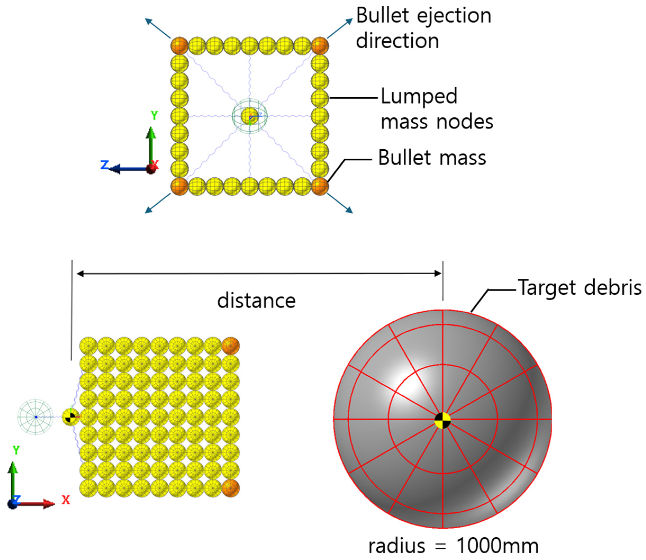
In this study, the proposed system consists of a net structure connected to four corner masses (bullets). Each bullet is deployed radially with an initial velocity generated by a spring-based mechanism, allowing the net to expand toward the target. After capture, a closure mechanism is activated to contract the net and secure the debris.
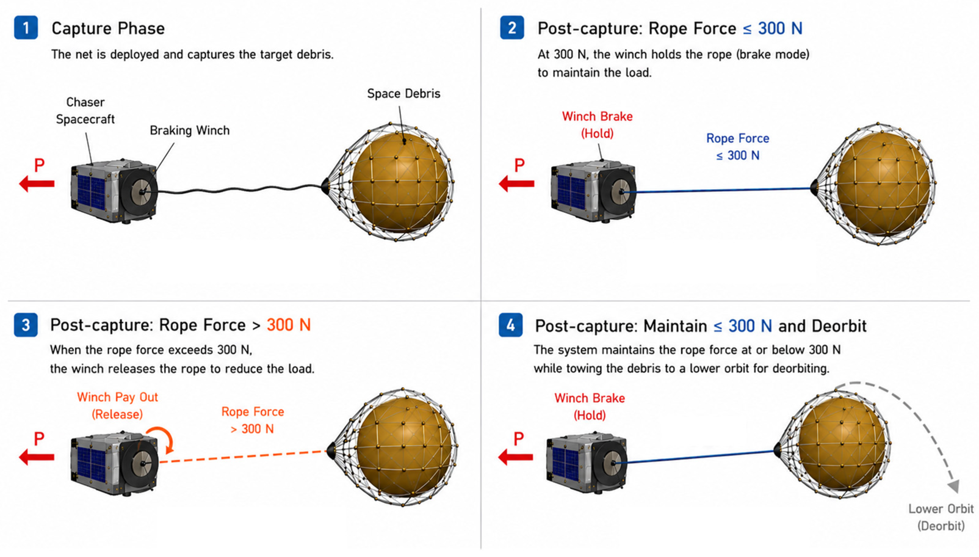
Figure 1 illustrates the operational concept of the proposed system. During the post-capture phase, the chaser spacecraft tows the debris through the pulling rope, where the rope force becomes a critical design constraint. When the rope force is below 300 N, the braking winch operates normally to regulate the rope tension and maintain stable control of the debris. However, when the rope force exceeds 300 N, the rope force reaches the maximum allowable load condition, and further force increase is limited to prevent structural failure or loss of the captured debris. This load-limiting behavior is a key design feature to ensure mission safety and reliability.
In particular, maintaining capture stability under tether-induced loading is essential for mission success. While previous studies have primarily focused on the capture phase, the stability of the net during post-capture towing has not been sufficiently addressed.
After successful capture, the chaser spacecraft maintains the debris in a secured configuration using the pulling rope and subsequently performs towing or deorbit maneuvers to remove the object from its operational orbit. In this study, the focus is placed on the capture and securing phase, while detailed orbital transfer, deorbit trajectory design, and fuel budget analysis are considered as part of future mission-level analysis.
The system is designed to capture debris with sizes ranging from 0.5 to 2 m and masses between 10 and 300 kg. It satisfies operational requirements for capture within a longitudinal distance of 3 to 9 m and a lateral offset of less than 1 m. Additionally, the tether line must withstand a maximum tensile load of 300 N after capture.
Based on these requirements, a multi-body dynamic analysis was performed using RecurDyn. The net was modeled as a node-based system to capture its flexible behavior, enabling comprehensive analysis of deployment, capture, and post-capture dynamics under tether loading conditions.

2.2. Net Design

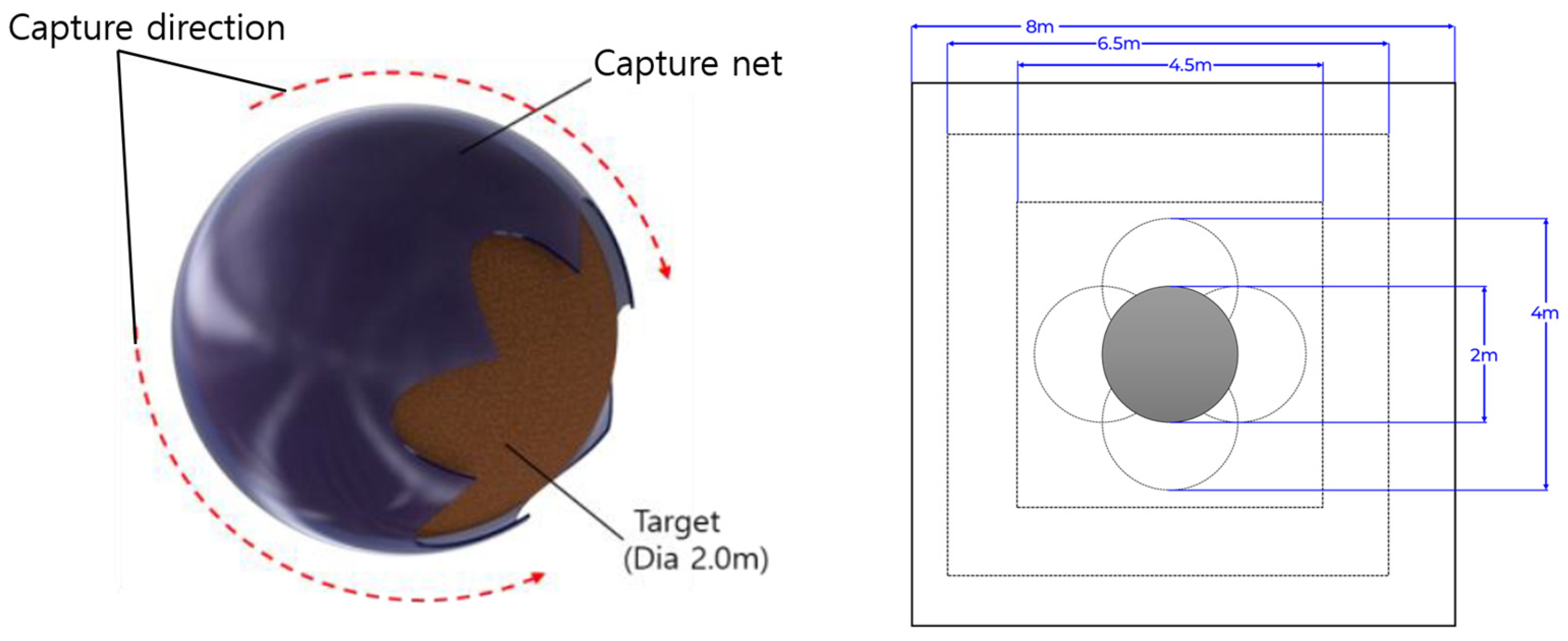
In this study, the net size was determined based on a formulation-driven design approach to ensure reliable capture of debris with a diameter of up to 2 m. Let r denote the radius of the target. To fully enclose the debris, the diagonal length of the square net must exceed the effective circumferential coverage of the target. Accordingly, the minimum side length s m i n is defined as in Equation (1).
s m i n 2 π r 2
a target with a diameter of 2 m ( r = 1 m), the minimum required side length is calculated as s m i n 4.44 m, corresponding to a net size of approximately 4.5 m × 4.5 m.
In practical scenarios, lateral position uncertainty must be considered. A maximum offset of Δ y = ± 1 m was incorporated, and the required net size s req is defined as in Equation (2).
s r e q = s m i n + 2 Δ y
This results in a minimum requirement of approximately 6.5 m × 6.5 m. Furthermore, to account for deployment asymmetry, ejection uncertainty, and dynamic motion of the target, a safety margin factor γ s was introduced. The final design size s d is defined as in Equation (3).
s d = γ s s r e q
In this study, a safety margin of approximately 20% was applied, resulting in a final net size of 8 m × 8 m. Figure 2 illustrates the geometric relationship between the designed net and the target debris. As shown, sufficient clearance is provided to accommodate positional uncertainty and dynamic motion, thereby improving the probability of successful capture.
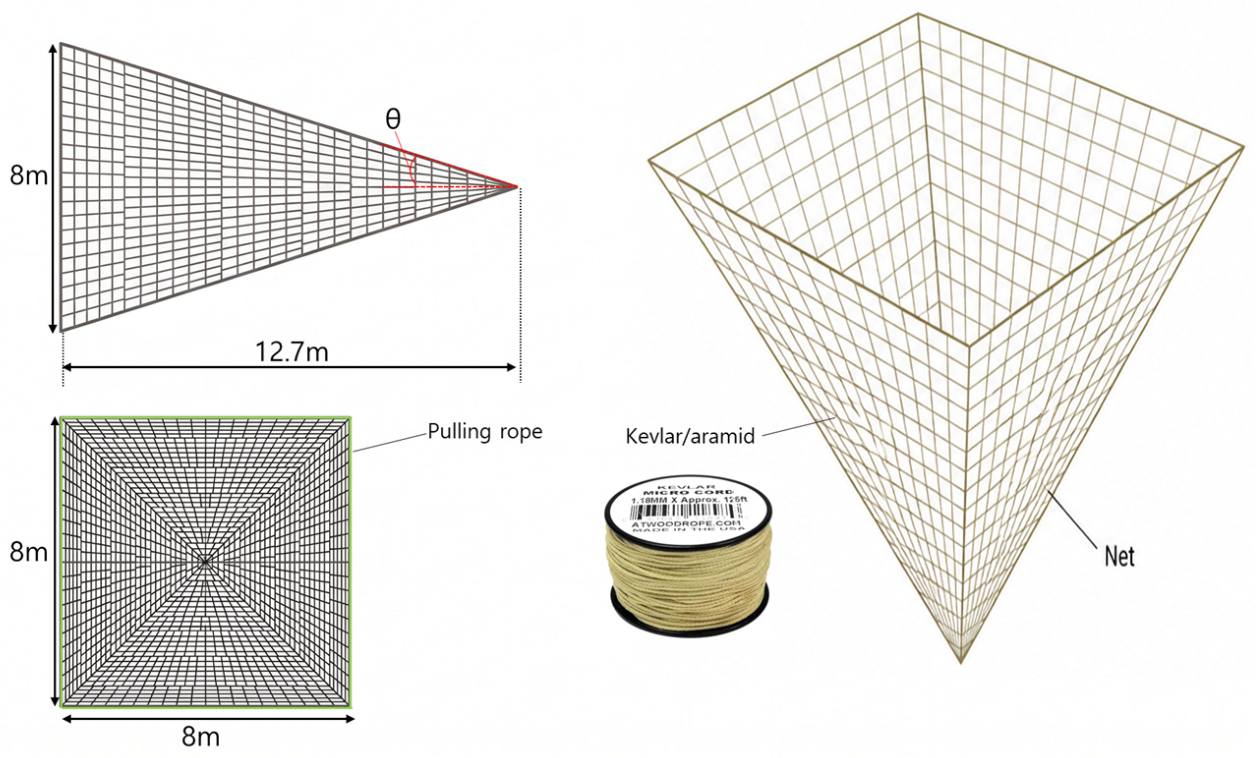
In addition, to prevent undesirable initial contact and entanglement between the net and the target during the capture process, a pyramid-shaped net configuration, as shown in Figure 3, was adopted. This configuration gradually converges toward the center during deployment, guiding the target into the capture region and improving capture stability. Compared to a flat net structure, this design enhances the probability of successful capture by facilitating controlled initial contact.
Furthermore, to satisfy the post-capture tensile load requirement, a high-strength fiber material, Micro cord Kevlar/aramid (320 uB, diameter 1.18 mm, Atwood Rope MFG, Millersport, OH, USA), was applied. This material provides a tensile strength exceeding 436 N, which sufficiently satisfies the required load condition of 300 N. As a result, structural stability can be maintained during the towing phase after capture.
The main design parameters of the net are summarized in Table 1. The side length of the net was set to 8 m, with a total deployed length of 12.7 m and an ejection angle of 18°. The mesh cell size was limited to a perimeter of less than 1.5 m to ensure both capture efficiency and structural integrity. The total mass of the net was designed to be approximately 1.6 kg, considering both launch constraints and operational efficiency.

2.3. Simulation Environment and Dynamic Modeling

To evaluate the deployment and capture behavior of the proposed system, a multibody dynamic model was developed using RecurDyn. This subsection describes the governing equations, node-based net modeling approach, contact formulation, and simulation conditions employed in the numerical analysis.

2.3.1. Governing Equations

The dynamic behavior of the tethered-net system was analyzed using a multibody dynamic formulation implemented in RecurDyn. The net structure was discretized into lumped node masses interconnected by spring-damper elements. The nonlinear dynamic response of the flexible net during deployment and capture was solved in the time domain using an implicit numerical integration scheme provided by RecurDyn.
The equation of motion for each node is governed by Newton’s second law and can be expressed as in Equation (4).
m i x ¨ i = F i i n t + F i e x t
where m i is the mass of the i -th node, x i is the position vector, F i int represents internal forces due to spring-damper connections, and F i ext denotes external forces such as contact forces and pulling-rope tension.
The internal forces are primarily generated by the deformation of tether elements connecting adjacent nodes and are modeled using a spring-damper formulation as follows:
F i j = k i j l i j l i j 0 n i j + c i j l ˙ i j n i j
where k i j and c i j are the stiffness and damping coefficients, respectively, l i j and l i j 0 denote the current and initial lengths, and n i j is the unit direction vector.
Contact interactions between the net and the target are modeled using a nonlinear contact formulation. The contact force is computed using a penalty-based approach, where the repulsive force is proportional to the depth of penetration.
The resulting system constitutes a nonlinear, high-degree-of-freedom dynamic problem. Time integration is performed using RecurDyn to simulate the deployment, capture, and post-capture behavior of the net system.

2.3.2. Net Modeling

A node-based modeling approach was adopted to represent the flexible behavior of the net. The net is idealized as a grid structure composed of multiple nodes connected by linear elements, where each node is modeled as a lumped mass particle.
The net structure was modeled as a two-dimensional interconnected flexible mesh composed of lumped node masses connected by one-dimensional spring-damper elements. The spring-damper connections represent the axial tensile behavior and energy dissipation between neighboring nodes, enabling large deformation and nonlinear dynamic motion of the net during deployment and capture.
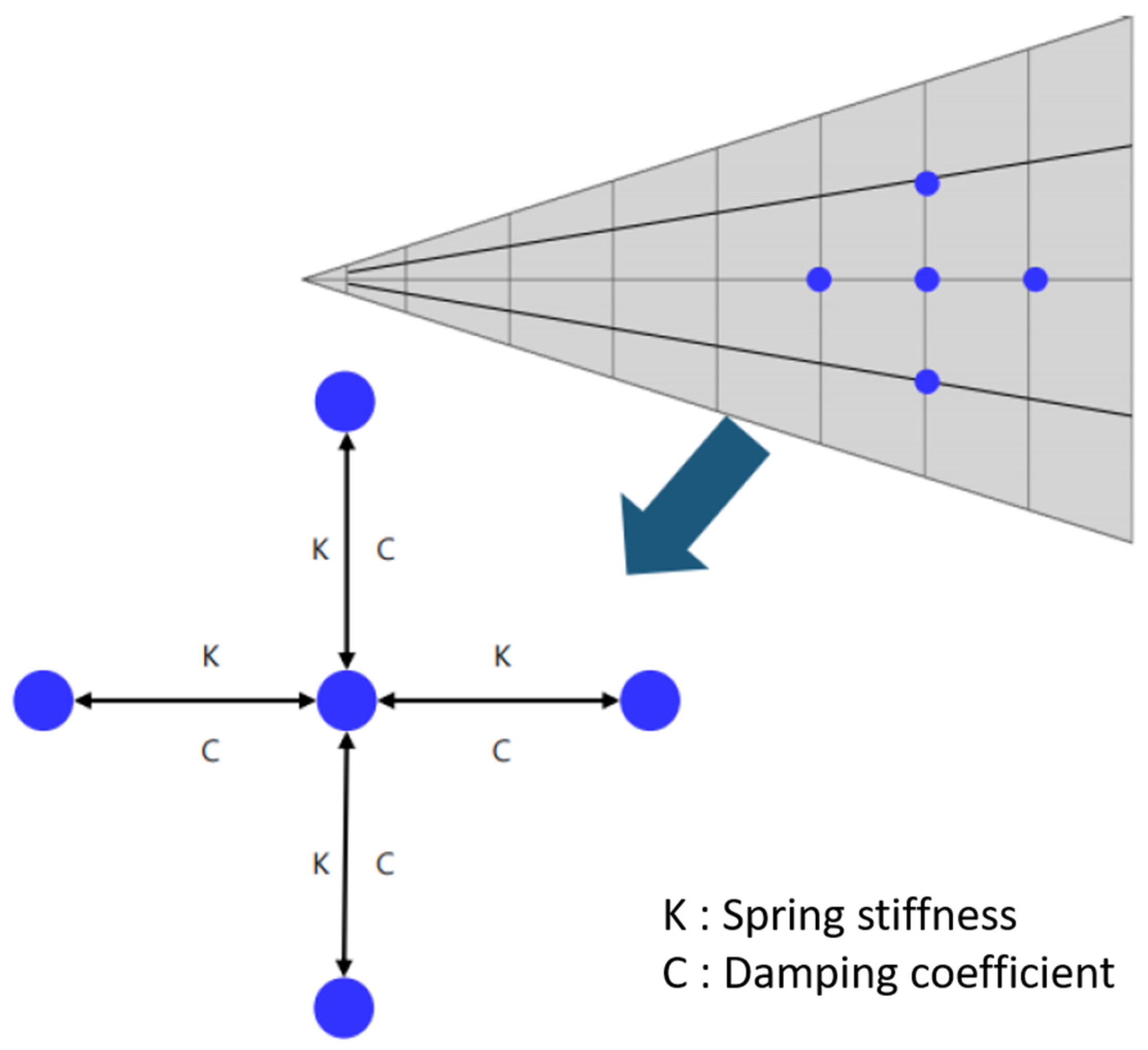
Each node interacts with its neighboring nodes through axial elements modeled as spring-damper components with stiffness k and damping coefficient c , as illustrated in Figure 4. In this formulation, the net is discretized into lumped-mass nodes interconnected by axial elements, where force transmission occurs primarily along the tensile direction. This modeling approach captures the dominant tensile behavior of the net structure.
The net is discretized into N x × N y nodes, and each node is connected to up to four adjacent nodes. Additional diagonal connections are introduced to improve shear stiffness and structural stability.
The mass of each node is uniformly distributed as expressed in Equation (6).
m i = m n e t N
where m n e t is the total mass of the net and N is the total number of nodes, such that the mass is uniformly distributed among all nodes.
The node density was determined based on the designed mesh cell size of the net. The same node configuration was used for all simulation cases to ensure consistent comparison of the effects of ejection distance, ejection angle, and ejection velocity. The discretization was kept constant throughout the simulations to avoid numerical bias in the parametric comparison.
Each tether element transmits force only under tensile deformation. The net tension T is activated only when the strain ε is positive, as expressed in Equation (7) [24].
T = k ε + c ε ˙ ,                       ε > 0 0 ,                                           ε 0
The strain is defined as in Equation (8), where L denotes the current length and L 0 represents the initial length.
ε = L L 0 L 0
This modeling approach enables the net to behave as a tension-dominated flexible structure, effectively capturing large deformation and nonlinear dynamics.

2.3.3. Contact and Tether Modeling

The interaction between the net and the target is modeled using a nonlinear contact formulation based on a penalty method. The contact force consists of a repulsive component proportional to the penetration depth and a damping component proportional to the penetration velocity, expressed as in Equation (9).
F c = k c δ n + c c δ ˙ n
where k c is the contact stiffness, c c is the damping coefficient, δ is the penetration depth, and n is the unit normal vector at the contact interface. This formulation accounts for both impact response and energy dissipation during collision. Contact interactions between the net, target, and pulling rope were modeled using the contact algorithm provided in RecurDyn.
The tether system is modeled as a nonlinear spring-damper element that only supports tensile forces. A unilateral constraint is applied such that no force is transmitted under compressive conditions. The tether force is defined as in Equation (10)
F t = k t l l 0 n + c t l ˙ n ,       l > l 0 0 ,                                                               l l 0
where k t and c t are the stiffness and damping coefficients, and l and l 0 represent the current and initial lengths, respectively.
To ensure system stability during post-capture towing, a maximum tether force constraint is imposed.
A closure mechanism is implemented by gradually reducing the tether length L over time, based on the deformation relation defined in Equation (8), ensuring that the captured debris remains securely confined within the net.

2.3.4. Simulation Conditions

Dynamic simulations were performed using RecurDyn based on a multi-body dynamics formulation. The simulations were conducted under microgravity conditions (10−5 g), neglecting external forces such as aerodynamic drag.
The target was modeled as a stationary sphere to reduce uncertainties in the dynamic model and to isolate the effects of the primary design parameters, including ejection distance, ejection angle, and ejection velocity. If an irregular and tumbling target were introduced at this stage, the capture behavior would be affected by multiple coupled factors, such as target geometry, attitude motion, contact location, and rotational energy. Therefore, a simplified spherical target was adopted as a controlled baseline condition for evaluating the net deployment characteristics, capture envelope, and winch-driven closure mechanism.
The initial conditions and simulation parameters were defined to represent realistic capture scenarios, and the main conditions are summarized in Table 1. The initial longitudinal distance between the chaser and the target was set to 3 m and 9 m, while the lateral offset was limited to within 1 m. The target was assumed to be stationary. The initial velocity of the bullets was set to 8 m/s, 10 m/s, 12 m/s, and 14 m/s, and the ejection angles were defined as 15°, 18°, and 20°. The mass of each bullet was set to 2.35 kg.
As illustrated in Figure 5, the net system consists of 4 bullets located at the corners of the net, which are connected to a winch through pulling ropes. The bullets are ejected to deploy the net, and after the net passes over the target, the winch is activated to reel in the pulling ropes, inducing contraction of the net and enabling target capture. This winch-driven closure mechanism plays a critical role in the capture process by converting the deployed net into a closed configuration.
The model parameters were determined based on the node-based formulation and the contact and tether models described in Section 2.3, while maintaining stable numerical convergence and physically reasonable deployment and contact behavior throughout the simulations. The performance evaluation was conducted based on capture success, complete enclosure of the target, and post-capture stability under rope tension.

3. Results and Discussion

This section presents the simulation results obtained from the multibody dynamic analysis. The effects of target distance, ejection angle, and ejection velocity on net deployment behavior are first investigated. Subsequently, the capture process and capture performance under positional and velocity uncertainties are analyzed to identify the optimal operating conditions of the proposed system.

3.1. Net Deployment Characteristics According to Target Distance

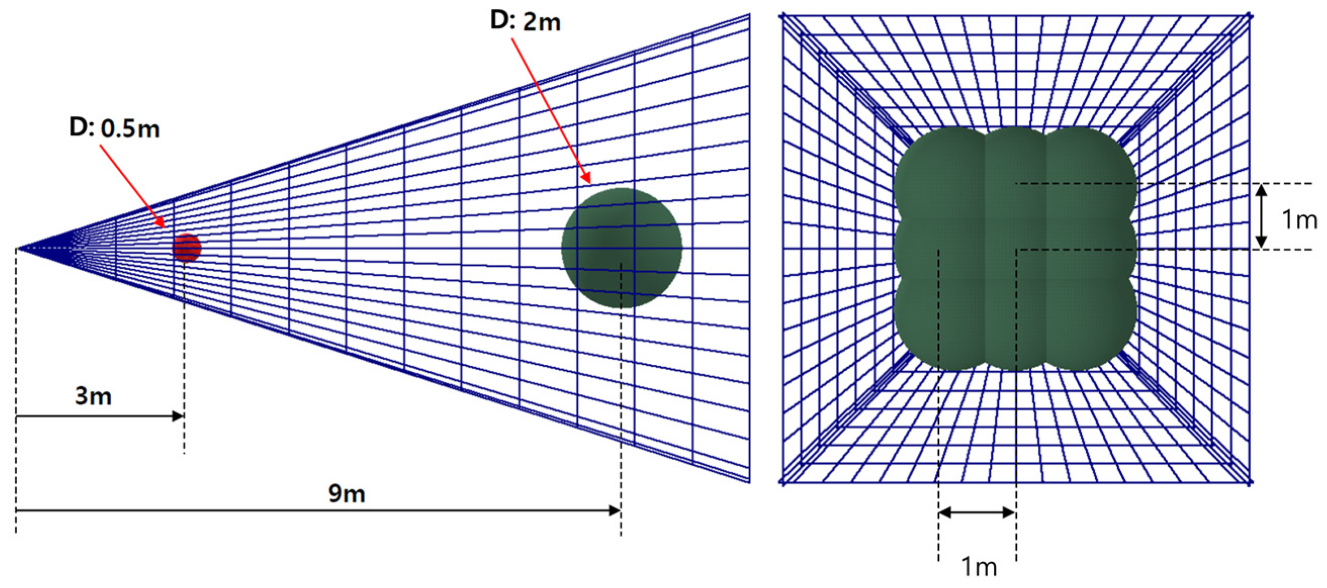
The proposed net system was designed to capture a target with a diameter of 0.5 m at a relative distance of 3 m and a target with a diameter of 2 m at the maximum relative distance of 9 m. In addition, considering possible pointing and relative position errors during proximity operation, the system is required to capture the target under a lateral offset of up to 1 m from the target center.
To evaluate the deployment characteristics according to ejection distance, the ejection angle and ejection velocity were fixed at 18 ° and 10 m/s, respectively. The relative distances were then set to 3 m and 9 m, and the deployed net shape and capture envelopes were compared. Figure 6 illustrates the net configuration and target position for each distance condition.
As shown in Figure 6, at a distance of 3 m, the target with a diameter of 0.5 m is included within the net even during the early deployment stage, satisfying the short-range capture requirement. At a distance of 9 m, the net reaches a sufficiently expanded configuration and forms a capture envelope capable of enclosing a target with a diameter of 2 m. Moreover, even when the target center is laterally offset by 1 m from the net center, the target remains inside the capture region.
Therefore, the ejection condition of 18° and 10 m/s provides sufficient deployment capability to capture debris with diameters ranging from 0.5 to 2 m over the relative distance range of 3–9 m.

3.2. Net Deployment Characteristics According to Ejection Distance

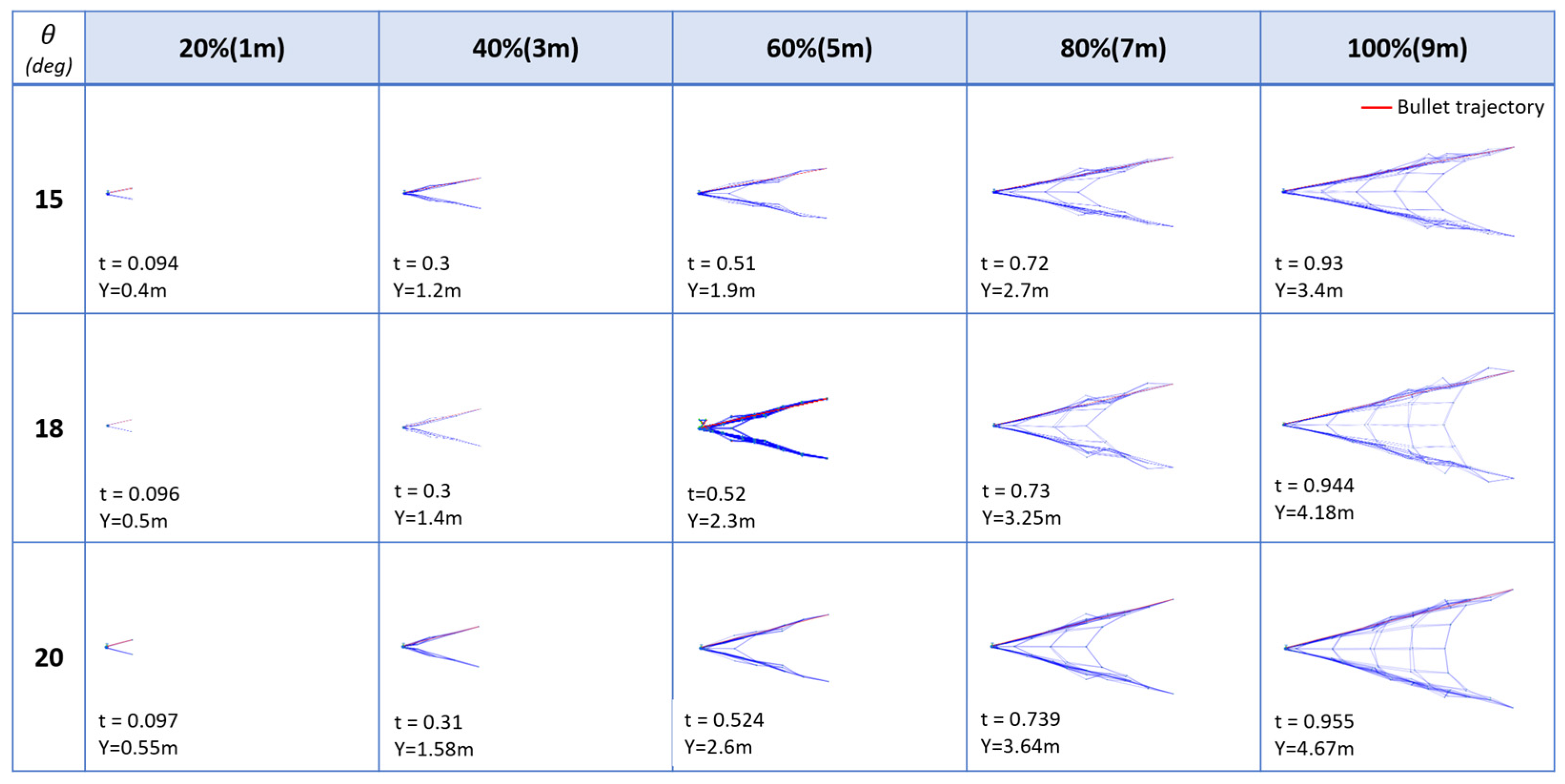
Next, the deployment characteristics of the net are analyzed with respect to the ejection angle. The ejection velocity was fixed at 10 m/s, and the deployment behavior was evaluated for ejection angles of 15°, 18°, and 20°. Figure 7 illustrates the time evolution of the net deployment at different distances (1–9 m) for each angle.
For the 15° case, the net maintains a relatively narrow opening during deployment. The net reaches the target distance of 9 m at approximately 0.93 s, and the maximum opening width is about 3.4 m. While this condition allows capture, it provides a limited margin when considering lateral position errors.
When the ejection angle is increased to 18°, the net forms a wider and more stable opening configuration. At 9 m, the opening width reaches approximately 4.0–4.2 m, which provides sufficient capture margin for a lateral offset of up to 1 m. This condition represents a balanced trade-off between deployment performance and capture reliability.
For the 20° case, the net expands further, reaching an opening width of approximately 4.6 m at 9 m. However, excessive deployment leads to increased tether length during the retrieval phase, requiring a larger winch capacity and increasing system complexity. In addition, larger openings may introduce structural instability and deformation.
As shown in Figure 7, all tested ejection angles (15–20°) enable capture under a lateral offset of 1 m. However, considering safety margin, retrieval efficiency, and system constraints, it is desirable to limit the net opening to approximately 4–4.2 m at 9 m.
Therefore, an ejection angle of 18° is identified as the optimal condition, providing sufficient capture capability while maintaining system efficiency and stability.

3.3. Net Deployment Characteristics According to Ejection Velocity

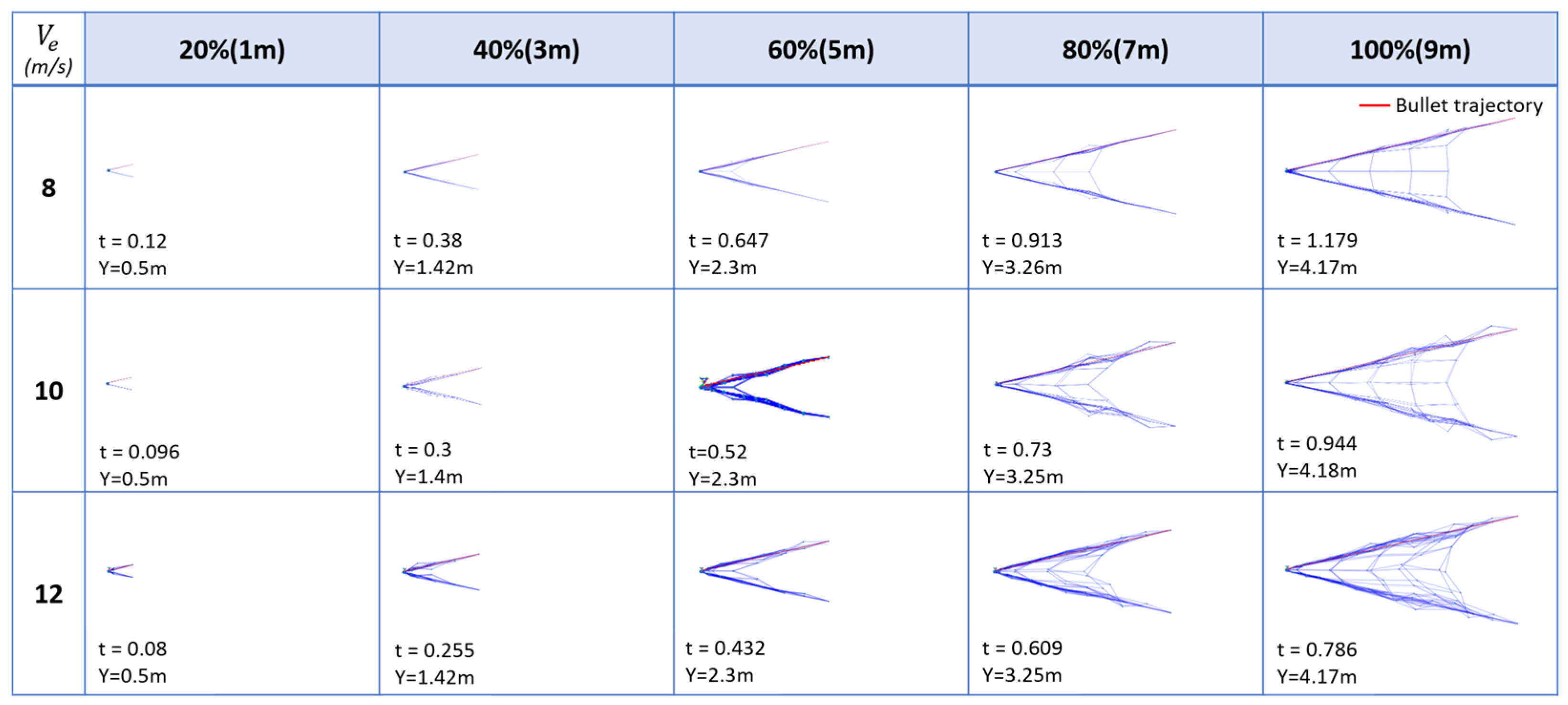
Figure 8 shows the net deployment characteristics according to ejection velocity. The ejection velocity is determined by the spring-driven mechanism used to launch the bullets. In this study, the spring displacement x was designed as 0.1 m, and the mass of each bullet was set to 2.35 kg. Spring stiffness was determined from the required bullet ejection velocity based on the spring energy relation, as expressed in Equation (11).
1 2 k x 2 = 1 2 m v 2
where k is the spring constant, x is the spring displacement, m is the bullet mass, and v is the ejection velocity. From Equation (11), the spring constant can be calculated as follows:
k = m v 2 x 2
The maximum spring force acting on each bullet is calculated as in Equation (13).
F s = k x = m v 2 x
Based on these relations, the required spring constants for velocities of 8 m/s, 10 m/s, and 12 m/s are approximately 15,040 N/m, 23,500 N/m, and 33,840 N/m, respectively. The corresponding maximum spring forces for a single bullet are approximately 1504 N, 2350 N, and 3384 N. This indicates that both the spring stiffness and the required actuation force increase proportionally to the square of the ejection velocity.
As shown in Figure 8, increasing the ejection velocity reduces the time required for the net to reach the target distance. At 9 m, the arrival times are approximately 1.18 s, 0.94 s, and 0.79 s for 8 m/s, 10 m/s, and 12 m/s, respectively. However, when the ejection angle is fixed, the final opening shape and size of the net remain nearly identical regardless of the velocity. This indicates that the opening geometry is governed primarily by the ejection angle, while the velocity mainly affects the deployment timing and dynamic response.
The tension acting on the net can be approximated from the change in bullet momentum, as expressed in Equation (14).
F = d p d t m v Δ t
Assuming four bullets act symmetrically, the total axial tension is expressed as in Equation (15).
F t o t a l = 4 · m v Δ t cos θ
where Δ t is approximately 0.3 s and θ is the ejection angle.
The calculated tension values for different velocities and ejection angles are summarized in Table 2. As shown in Table 2, the tension increases almost linearly with the ejection velocity, while the influence of the ejection angle is relatively small within the range of 15–20°.
As indicated in Table 2, at an ejection velocity of 10 m/s, the tension remains within approximately 300 N for ejection angles of 18° and 20°, while it slightly exceeds the limit at 15°. In contrast, at 12 m/s, the tension exceeds 300 N for all angle conditions, reaching values above 350 N.
These results demonstrate that increasing the ejection velocity reduces the deployment time but significantly increases both the required spring force and the net tension. Therefore, considering structural safety, system constraints, and deployment timing, the ejection velocity should be limited to 10 m/s or lower in this study.

3.4. Capture Performance Analysis

In the previous sections, the net deployment characteristics were analyzed with respect to ejection angle and velocity. Based on these results, the optimal condition satisfying the design requirements—capturing a target with a diameter of up to 2 m at a distance of 9 m while maintaining the net tension below 300 N—was identified as an ejection angle of 18° and an ejection velocity of 10 m/s.
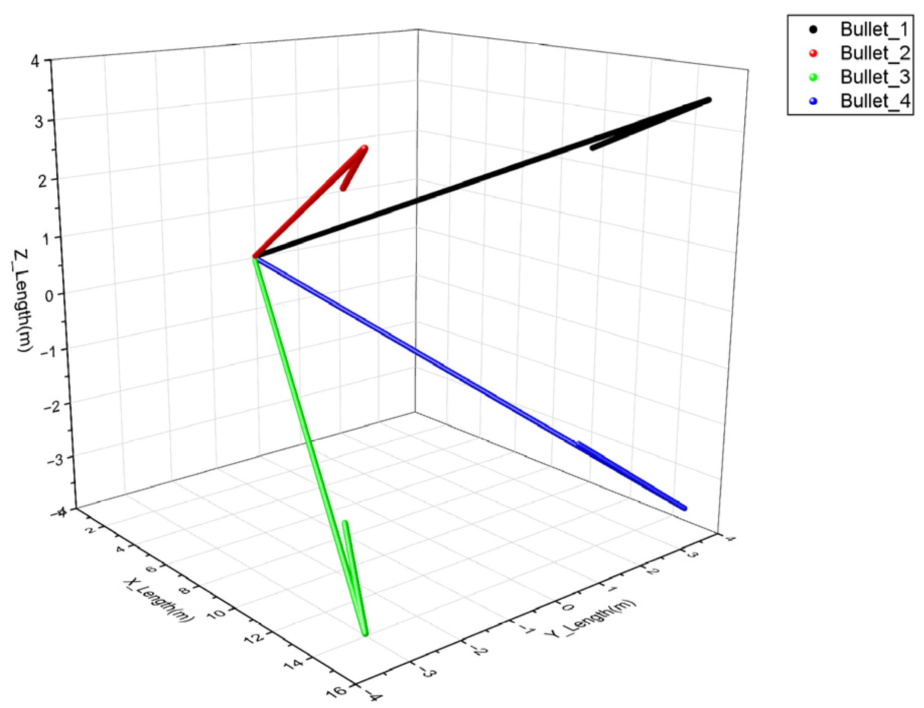
Figure 9 shows the trajectories of the four bullets under the optimal condition. The bullets are symmetrically distributed in space, forming the boundary of the net deployment. The trajectories confirm that the net maintains a stable opening configuration and forms an enclosure structure around the target.
Under this condition, the net reaches a fully deployable state capable of enclosing the target at approximately 10 m, corresponding to a time of about 1.05 s. However, considering relative velocity uncertainties and system delays, the winch activation timing was set at 11 m (approximately 1.16 s), ensuring sufficient capture margin and stable closure behavior.
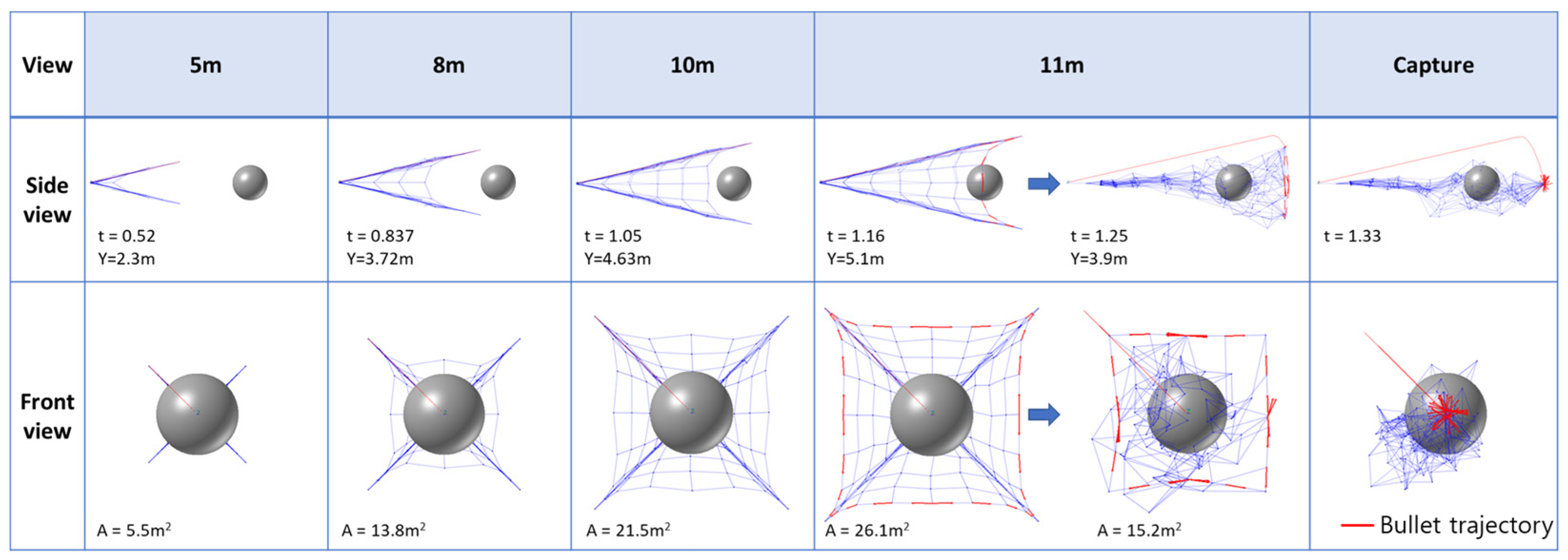
Figure 10 shows the capture process of the designed net for the target object. The target is modeled as a sphere with a diameter of 2 m, and the initial distance is set to 9 m. During the initial deployment phase, the net expands in a conical shape while approaching the target, and the opening area gradually increases with distance. The net reaches opening areas of approximately 5.29   m 2 at 5   m , 13.84   m 2 at 8 m, and 21.44   m 2 at 10 m, forming a geometry capable of fully encompassing the target. However, no direct contact occurs between the net and the target before reaching 11 m.
When the net passes the target at 11 m, corresponding to t = 1.16   s , the capture phase is initiated by activating the winch. At this moment, the net has fully expanded beyond the target, and the winch begins reeling in the pulling rope. The tension transmitted through the pulling rope induces rapid contraction of the net, particularly at the edge nodes, causing the net opening to close around the target.
The winch completes the reeling process within approximately 0.2 s, leading to a rapid reduction in the net opening. As a result, at t = 1.33   s , the net forms a closed configuration that fully encloses the target, ensuring a stable capture state. Unlike contact-driven capture mechanisms, the proposed system captures the target by allowing the net to fully pass over the target before initiating closure. This approach reduces initial impact forces and improves robustness against positional uncertainties.
These results indicate that successful capture is governed not only by the deployment geometry but also by the timing of winch activation and the reeling speed of the pulling rope. In particular, initiating the winch at t = 1.16   s , when the target is fully enclosed within the net, is a critical operational condition for achieving reliable capture.
Figure 10 shows the capture process of the designed net for the target object. The target is modeled as a sphere with a diameter of 2 m, and the initial separation distance is set to 9 m. During the initial deployment phase, the net expands in a conical shape while approaching the target, and the opening width and capture envelope gradually increase with distance. At t = 1.05   s , when the net passes the 10 m position, the net expands to approximately 4.63 m in the y -direction, forming a geometry sufficient to include the 2 m diameter target.
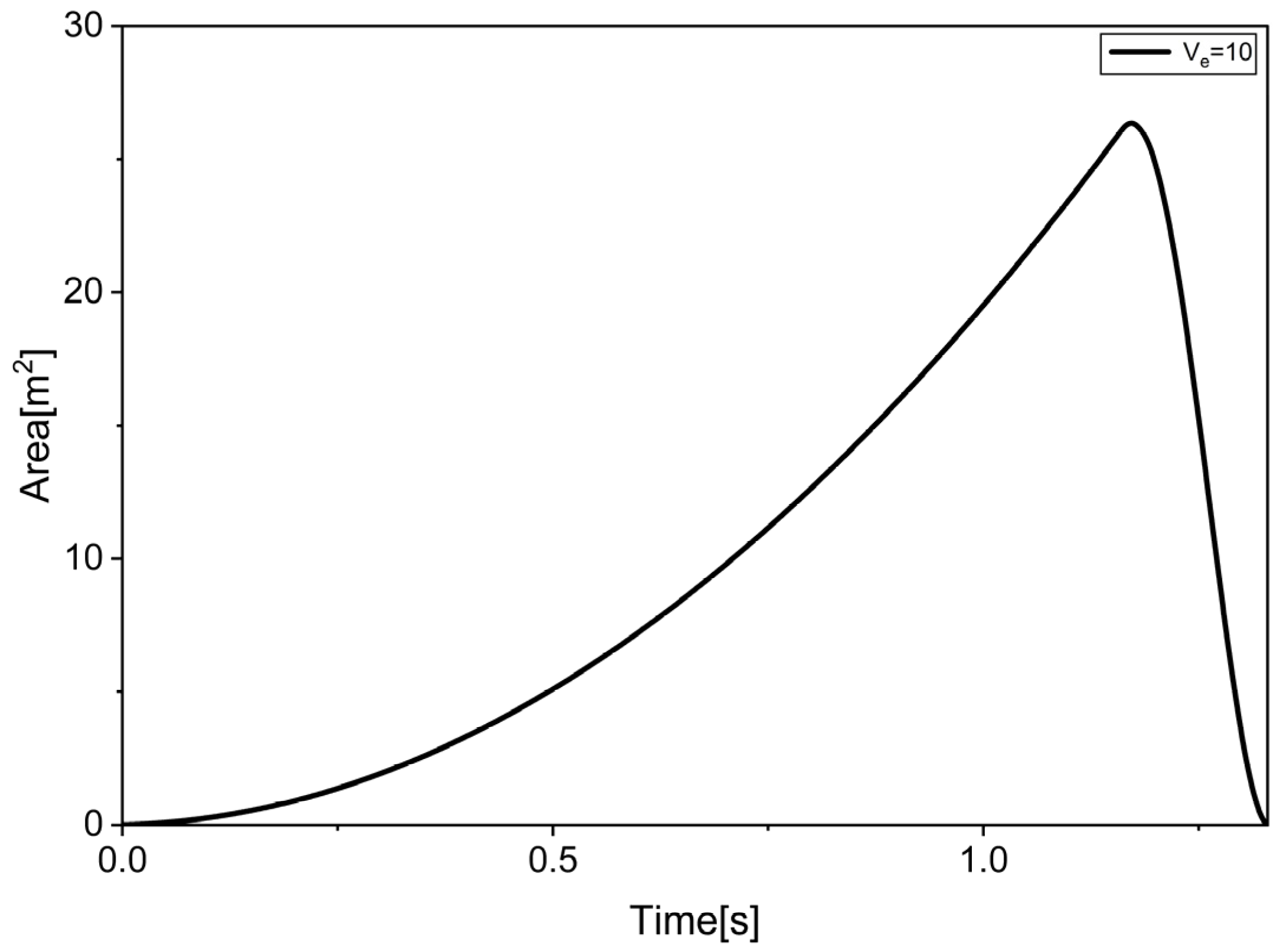
Figure 11 shows the variation in the capture area over time. The capture area gradually increases before winch activation and reaches its maximum near t = 1.16   s . After this point, the winch starts reeling in the pulling rope, causing the net opening to contract rapidly. Consequently, the capture area decreases sharply, indicating that the target is captured by closing the net after it has sufficiently passed over the target.
The capture performance under lateral velocity errors can be evaluated based on the opening width in the y -direction at the 10 m position. The capture performance is evaluated using the y -direction opening width at the 10 m position, where the net expands to approximately 4.63 m, forming a geometry sufficient to enclose a 2 m diameter target.
The maximum allowable lateral velocity can be estimated by dividing the available lateral margin by the time required to reach the 10 m position. The allowable lateral velocity error is defined as in Equation (16):
v L , m a x = y m a x y 0 t
where v L , m a x is the maximum allowable lateral relative velocity, Δ y m a x represents the maximum allowable lateral offset determined by the net opening width, Δ y 0 is the initial lateral position error of the target, and t is the time required for the net to reach the 10 m position.
When no initial positional error is present, the maximum allowable lateral velocity error is approximately 1.25   m / s . When an initial lateral positional error of 1 m is considered, the allowable maximum lateral velocity error decreases to approximately 0.30   m / s . Therefore, the lateral velocity errors in the range of 0.1 0.2   m / s considered in this study remain within the capture-capable range, demonstrating that the proposed net design ensures robust capture performance even under combined position and velocity uncertainties.

4. Conclusions

In this study, multibody dynamic analysis was performed to investigate the relationship between design parameters and capture performance of a tethered-net-based space debris capture system. A node-based modeling approach was adopted, in which the interactions between nodes were represented by spring-damper elements to capture large deformation and nonlinear behavior. The analysis was conducted using the commercial multibody dynamics software RecurDyn, considering key parameters such as ejection distance, angle, and velocity.
The results show that the deployment characteristics of the net are strongly influenced by ejection velocity and angle. Excessive ejection velocity leads to structural instability and increased rope tension due to rebound effects after full deployment. In particular, the tension analysis indicates that the rope force remains below the allowable limit of 300 N at an ejection velocity of 10 m/s, while it exceeds the allowable limit at velocities above 12 m/s. Since the tensile strength of the selected Kevlar/aramid fiber exceeds 436 N, no structural failure of the net was predicted under the operating condition of 10 m/s. This indicates that the proposed operating condition satisfies both the deployment performance requirement and the structural safety requirement of the net. The ejection angle also significantly affects the opening geometry and deployment stability, with 18° providing the most suitable deployment shape at the target distance.
The capture process analysis demonstrates that the proposed system operates by allowing the net to fully pass over the target before activating the winch to reel in the pulling rope and close the opening. The winch is activated at t = 1.16   s , and the capture process is completed within approximately 0.2 s. Unlike conventional contact-driven capture approaches, the proposed winch-driven closure mechanism minimizes initial impact forces and improves capture stability under positional and velocity uncertainties. In addition, the capture performance under relative position and velocity uncertainties were quantitatively evaluated. The results indicate that the allowable lateral relative velocity is approximately 1.25 m/s without initial positional error and decreases to approximately 0.30 m/s when a 1 m positional error is considered.
The proposed system provides practical engineering relevance for controlled close-proximity ADR missions by quantitatively relating ejection conditions, rope tension, and capture performance. In particular, the derived allowable lateral velocity criterion and rope tension limits provide useful engineering guidelines for the design and operation of tethered-net-based debris capture systems. The optimal operating condition identified in this study is an ejection angle of 18° and an ejection velocity of 10 m/s.
It should be noted that the proposed system is intended for controlled close-proximity ADR missions targeting pre-identified debris objects, rather than autonomous wide-area deployment in crowded orbital environments. Although the present study focuses on simplified baseline capture scenarios, the results demonstrate the applicability of the proposed approach to realistic net-based ADR operations in LEO environments. Future work will focus on extending the analysis to rotating and non-cooperative targets with more complex geometries.

Author Contributions

Author Contributions: Conceptualization, H.S., H.L. and G.P.; methodology, H.L. and S.J.; software, H.S.; validation, H.S., H.L. and S.J.; formal analysis, H.S. and H.L.; investigation, H.S., H.L., T.J. and S.J.; resources, T.J.; data curation, H.S.; writing—original draft preparation, H.S. and G.P.; writing—review and editing, H.L. and G.P.; visualization, H.S.; supervision, G.P.; project administration, G.P.; funding acquisition, G.P. All authors have read and agreed to the published version of the manuscript.

Funding

This work was supported by the Civil-Military Technology Cooperation Program funded by the Government of the Republic of Korea (Ministry of Trade, Industry and Energy and Defense Acquisition Program Administration) (No. 22-CM-EC-36).

Data Availability Statement

The data presented in this study are available on reasonable request from the corresponding author.

Conflicts of Interest

The authors declare no conflicts of interest.

References

  1. Zhang, Y.; Cheng, B.; Jiang, F.H.; Baoyin, H.; Liu, J.Y.; Zhan, X.Q. Space sustainability via flexible controlled expandable net for multiple irregular debris removal. Acta Astronaut. 2026, 238, 925–939. [Google Scholar] [CrossRef]
  2. Tang, C.; Deng, Y.Q.; Bai, Z.F.; Wei, C.; Zhao, Y. Dynamics Analysis of Space Netted Pocket System Capturing Non-Cooperative Target. Appl. Sci. 2023, 13, 10377. [Google Scholar] [CrossRef]
  3. Thomas, J.; Colvin, J.K.; Wusk, G. Cost and Benefit Analysis of Orbital Debris Remediation; NASA: Washington, DC, USA, 2023. [Google Scholar]
  4. Shin, H.C.; Jang, M.; Hwang, U.J.; Sim, C.H.; Park, J.S. Capture Simulation Using Space-Nets for Space Debris in Various Motions. Int. J. Aeronaut. Space 2023, 24, 547–558. [Google Scholar] [CrossRef]
  5. Ren, S.Y.; Yang, X.H.; Wang, R.L.; Liu, S.Q.; Sun, X.J. The Interaction between the LEO Satellite Constellation and the Space Debris Environment. Appl. Sci. 2021, 11, 9490. [Google Scholar] [CrossRef]
  6. Delisle, M.H.; Christidi-Loumpasefski, O.O.; Yalçin, B.C.; Li, X.; Olivares-Mendez, M.; Martinez, C. Hybrid-Compliant System for Soft Capture of Uncooperative Space Debris. Appl. Sci. 2023, 13, 7968. [Google Scholar] [CrossRef]
  7. Yue, S.; Li, M.S.; Zhao, Z.; Du, Z.H.; Wu, C.B.; Zhang, Q.Z. Parameter Analysis and Experiment Validation of Deployment Characteristics of a Rectangular Tether-Net. Aerospace 2023, 10, 115. [Google Scholar] [CrossRef]
  8. Kim, S.; Song, D.; Kim, H.; Cho, H.; Park, J.S. Feasibility study of a nonexplosive net ejection mechanism for active space debris removal. Adv. Space Res. 2025, 76, 6379–6400. [Google Scholar] [CrossRef]
  9. Chen, Q.Q.; Zhang, Q.B.; Gao, Q.Y.; Feng, Z.W.; Tang, Q.G.; Zhang, G.B. Design and optimization of a space net capture system based on a multi-objective evolutionary algorithm. Acta Astronaut. 2020, 167, 286–295. [Google Scholar] [CrossRef]
  10. Han, D.; Dong, G.Q.; Huang, P.F.; Ma, Z.Q. Capture and detumbling control for active debris removal by a dual-arm space robot. Chin. J. Aeronaut. 2022, 35, 342–353. [Google Scholar] [CrossRef]
  11. Nagavarapu, S.C.; Mogan, L.B.; Chandran, A.; Hastings, D.E. CubeSats for space debris removal from LEO: Prototype design of a robotic arm-based deorbiter CubeSat. Adv. Space Res. 2025, 75, 6896–6910. [Google Scholar] [CrossRef]
  12. Campbell, J.C.; Hughes, K.; Vignjevic, R.; Djordjevic, N.; Taylor, N.; Jardine, A. Development of modelling design tool for harpoon for active space debris removal. Int. J. Impact Eng. 2022, 166, 104236. [Google Scholar] [CrossRef]
  13. Mao, L.J.; Zhao, W.; Pang, Z.J.; Gao, J.D.; Du, Z.H. Study on the penetration characteristics of conical harpoon on rotating space debris. Adv. Space Res. 2024, 74, 4109–4122. [Google Scholar] [CrossRef]
  14. Botta, E.M.; Miles, C.; Sharf, I. Simulation and tension control of a tether-actuated closing mechanism for net-based capture of space debris. Acta Astronaut. 2020, 174, 347–358. [Google Scholar] [CrossRef]
  15. Pandie, A.R.; Kojima, H. Numerical and experimental study on effects of net-bullet ejection angles and initial distances on space-debris capture. Acta Astronaut. 2025, 226, 361–374. [Google Scholar] [CrossRef]
  16. Kato, Y.; Kojima, H.; Trivailo, P.M. Performance evaluation of tether-net deployment with adjustable ejection angle. Adv. Space Res. 2024, 73, 2471–2487. [Google Scholar] [CrossRef]
  17. Zhen, M.; Cao, L.; Yang, L.P.; Sheng, T.; Liu, H.T. Space Net Capture Parameters Analysis Considering Impact Dynamics. Space-Sci. Technol. 2025, 5, 0249. [Google Scholar] [CrossRef]
  18. Zhang, G.B.; Zhang, Q.B.; Feng, Z.W.; Chen, Q.Q.; Yang, T. A simplified model for fast analysis of the deployment dynamics of tethered-net in space. Adv. Space Res. 2021, 68, 1960–1974. [Google Scholar] [CrossRef]
  19. Ru, M.; Zhan, Y.; Cheng, B.; Zhang, Y. Capture Dynamics and Control of a Flexible Net for Space Debris Removal. Aerospace 2022, 9, 299. [Google Scholar] [CrossRef]
  20. Benvenuto, R.; Salvi, S.; Lavagna, M. Dynamics analysis and GNC design of flexible systems for space debris active removal. Acta Astronaut. 2015, 110, 247–265. [Google Scholar] [CrossRef]
  21. Shan, M.H.; Guo, J.; Gill, E. Deployment dynamics of tethered-net for space debris removal. Acta Astronaut. 2017, 132, 293–302. [Google Scholar] [CrossRef]
  22. Botta, E.M.; Sharf, I.; Misra, A.K.; Teichmann, M. On the simulation of tether-nets for space debris capture with Vortex Dynamics. Acta Astronaut. 2016, 123, 91–102. [Google Scholar] [CrossRef]
  23. Forshaw, J.L.; Aglietti, G.S.; Navarathinam, N.; Kadhem, H.; Salmon, T.; Pisseloup, A.; Joffre, E.; Chabot, T.; Retat, I.; Axthelm, R.; et al. RemoveDEBRIS: An in-orbit active debris removal demonstration mission. Acta Astronaut. 2016, 127, 448–463. [Google Scholar] [CrossRef]
  24. Chen, Q.Q.; Yang, Y.F.; Zhang, Q.B. Dynamic modeling of space tethered net considering folding-induced bending and storage bag interaction. Acta Astronaut. 2026, 238, 1082–1094. [Google Scholar] [CrossRef]
Figure 1. Operational concept of the net-based capture system with tension-regulated braking winch mechanism.
Applsci 16 05759 g001
Figure 2. Geometric design of the net based on capture requirements.
Applsci 16 05759 g002
Figure 3. Geometry and structural configuration of the designed net.
Applsci 16 05759 g003
Figure 4. Node-based modeling approach of the net.
Applsci 16 05759 g004
Figure 5. Configuration of the tethered net capture system model.
Applsci 16 05759 g005
Figure 6. Net deployment configuration and target position.
Applsci 16 05759 g006
Figure 7. Net deployment characteristics at different ejection angles.
Applsci 16 05759 g007
Figure 8. Net deployment characteristics for different ejection velocities.
Applsci 16 05759 g008
Figure 9. Three-dimensional trajectories of the bullets during net deployment under the optimal ejection condition.
Applsci 16 05759 g009
Figure 10. Time-dependent capture process of the net.
Applsci 16 05759 g010
Figure 11. Variation in the net capture area over time.
Applsci 16 05759 g011
Table 1. Simulation conditions and parameters.
ParameterCondition
d (m)θ (deg) v e (m/s)
Ejection
distance
Case 131810
Case 26
Case 39
Ejection
angle
Case 491510
Case 518
Case 620
Ejection
velocity
Case 79188
Case 812
Case 914
Table 2. Velocity–tension relationship for different ejection angles.
Velocity (m/s)Tension at 15° (N)Tension at 18° (N)Tension at 20° (N)
8242.2238.4235.6
10302.6298.0294.4
12363.3357.6353.4
14423.8417.2412.1
Disclaimer/Publisher’s Note: The statements, opinions and data contained in all publications are solely those of the individual author(s) and contributor(s) and not of MDPI and/or the editor(s). MDPI and/or the editor(s) disclaim responsibility for any injury to people or property resulting from any ideas, methods, instructions or products referred to in the content.