Article

Performance Analysis of an LPG-Fueled Micro Gas Turbine Under Extreme Climate Conditions

by
Harun Güçlü
Automotive Engineering Department, Faculty of Engineering, Bursa Uludağ University, 16059 Bursa, Türkiye
Appl. Sci. 2026, 16(11), 5372; https://doi.org/10.3390/app16115372
Submission received: 17 April 2026 / Revised: 17 May 2026 / Accepted: 25 May 2026 / Published: 27 May 2026

Abstract

In battery electric vehicles (BEVs), range-extended electric vehicles (REEVs) are gaining prominence due to range limitations, long charging times, and limited charging infrastructure. Range losses are particularly evident under extreme climate conditions, necessitating the development of efficient range-extender (RE) systems. In this study, a liquefied petroleum gas (LPG)-fueled, recuperator-equipped Micro Gas Turbine (MGT) was modeled as a standalone range-extending power unit using the Simcenter simulation environment, and its thermodynamic performance was examined under extreme climate conditions. While existing MGT studies in the literature generally focus on diesel-fueled systems, this study fills a significant gap in the literature by modeling the effects of using low-carbon, high-energy-density LPG. The performance of the MGT system was analyzed in extreme cold (−10 °C), standard (20 °C), and hot (45 °C) climates; at three different turbine inlet temperatures (1000, 1100, and 1250 K); and at three recuperator effectiveness settings (0.75, 0.85, and 0.95). The developed MGT system achieved a maximum thermal efficiency of 41.1% and a specific fuel consumption (SFC) of 188.67 g/kWh under cold climate conditions of −10 °C (263.15 K), a turbine inlet temperature (TIT) of 1250 K, and a recuperator effectiveness of 0.95. Consequently, specific CO2 emissions were reduced to 566.01 g/kWh. The study’s most significant contribution to the literature is that the developed system offers high thermal efficiency, low fuel consumption, and low emissions under extremely cold climate conditions (−10 °C), where electric vehicle batteries typically experience performance and range loss. The LPG-fueled micro gas turbine with a recuperator demonstrates the potential to serve as an efficient, low-emission and competitive auxiliary power unit (APU) for range-extender applications, particularly under extreme climatic conditions.

1. Introduction

In recent years, the automotive industry has undergone a rapid transition from internal combustion engine (ICE) vehicles to electric vehicles (EVs) to reduce carbon footprint and harmful emissions. Despite rapid advancements in electric vehicle (EV) technologies and increased battery capacities, consumer “range anxiety” remains a major obstacle to EV adoption globally [1,2,3]. However, despite advancements in battery technologies, high battery costs, limited charging infrastructure, and long charging times pose a significant range problem for electric vehicles [4,5]. Battery performance drops dramatically, especially in cold climates. The energy spent on cabin and battery thermal management during winter months results in a 25% to 31% decrease in EV range [6]. Additional thermal loads from low ambient temperatures limit battery discharge cycles, reducing electric vehicle range and negatively impacting battery life [7,8]. The Range-Extended Electric Vehicle (REEV) architecture stands out as a technology that bridges the gap to fully electric mobility by optimizing battery size and costs while reducing range anxiety. In this concept, when the battery charge level falls below a certain threshold, a range extender auxiliary power unit (APU), which operates mechanically independently of the wheels and directly drives the generator, activates to charge the battery while the vehicle is in motion [9,10]. Traditional REEV applications typically use piston internal combustion engines as power units. ICE-based range extenders (REs) compromise ride comfort due to high noise, vibration, and harshness (NVH) levels, while their high weight and size reduce the vehicle’s overall efficiency [11,12,13]. In this context, Micro Gas Turbines (MGTs), with their unique advantages, are perfect Auxiliary Power Unit (APU) candidates for the next generation of REEVs. MGTs offer near-zero NVH levels thanks to their few moving parts and a much higher power-to-weight ratio compared to piston engines [14].
In recent years, the literature has seen a growing number of studies on the design and system performance of MGT-based range extenders. Tan et al. [15] have demonstrated, both analytically and experimentally, that a 10 kW MGT is highly effective in maintaining the state of charge (SOC) during urban driving cycles (MUDC). Kim et al. [16] successfully modeled the dynamics of a 22 kW MGT rotor system and determined the stability requirements at high speeds (over 100,000 RPM). Karvountzis-Kontakiotis et al. [13], on the other hand, examined a MGT system with a nominal power of 30 kW and reported a thermal efficiency of 26% at the design point. In another study conducted by Ji et al. [17], a 10 kW MGT range extender model was designed for electric vehicles; with a turbine inlet temperature (TIT) of 1152 K, a pressure ratio of 3.2, and a recuperator effectiveness of 0.7, the system achieved a thermal efficiency of 35%, and the specific fuel consumption (SFC) was found to be 266 g/kWh. In a study conducted by Najib et al. [18], a gas turbine cycle was designed that includes a two-stage compressor, an intercooler, and a recuperator; the high-pressure stage consists of a cooled turbine, while the low-pressure stage consists of an uncooled turbine. The authors demonstrated that this compact architecture, which does not require a second combustion chamber, can achieve a theoretical thermal efficiency of 51.39%. In a study conducted by Duan et al. [19], it was demonstrated that integrating a regenerator into a micro gas turbine cycle can increase efficiency by up to 3.79% compared to a simple cycle, particularly at low power levels (6 kW) and under variable-speed operating conditions. In an experimental study conducted by Shah et al. [20] using a 25 kW microturbine generator under the NEDC driving cycle, the tests were carried out under ambient temperatures ranging from 10 to 18 °C: the system operated with an average net efficiency of 17% and a specific fuel consumption of 508 g/kWh under a constant power demand of approximately 6.5 kW (PDS1). In a study conducted by Wei et al. [21], a modular, regenerative micro-gas turbine system designed for unmanned aerial, land, and maritime platforms was presented. Based on the results of thermodynamic cycle analyses, it was demonstrated that, with a turbine inlet temperature of 1275 K and a pressure ratio of 5.0, using a regenerator with 90% design efficiency, a thermal efficiency of 37.3% and a specific fuel consumption (SFC) of 0.229 kg/(kWh) can be achieved at an electrical power output of 150 kW. Shah et al. [22] reported that increasing the inlet temperature reduces performance in a 25 kW MGT system; within the 10–18 °C range, the system achieved a net efficiency of 23% and a SFC of 398–408 g/kWh. They observed a linear decrease of 0.2 kW in power output for every 1 °C increase in ambient temperature above 14 °C. In addition, the effects of recuperator design on MGT efficiency [23,24] and how alternative fuel mixtures (ammonia/natural gas) alter the MGT emission profile [25] have been detailed in the current literature through numerical modeling.
It is observed that existing literature on range-extender micro gas turbines (MGTs) has largely focused on diesel-fueled systems. The effects of LPG (propane)—which has high energy density, is low-carbon, and is readily available within the existing automotive infrastructure—on system performance and specific CO2 emissions have not yet been comprehensively investigated. In this study, a LPG-fueled micro gas turbine equipped with a recuperator was modeled in the Simcenter Amesim environment. Using a 1-D (one-dimensional) simulation, the MGT’s performance was evaluated at −10 °C (263.15 K), 20 °C (293.15 K), and 45 °C (318.15 K); at three different recuperator efficiencies (0.75, 0.85, and 0.95); and at three different turbine inlet temperatures (TIT: 1000 K, 1100 K, and 1250 K). The primary research focus of this study is to analyze the thermodynamic performance and potential as a range extender (RE) of an LPG-fueled micro gas turbine power unit equipped with a recuperator under extreme climate conditions (particularly in a cold environment of −10 °C) where the electrochemical efficiency of batteries decreases. The one-dimensional (1-D) system-level modeling approach used to perform this analysis enables rapid parametric screening across a wide operational envelope at a significantly lower computational cost compared to 3-dimensional CFD-based studies in the literature. On the other hand, a fundamental limitation of this method is its inability to directly solve complex 3D aerodynamic losses and local flow phenomena in a physically accurate manner. To minimize this methodological limitation and ensure the reliability of the results, the component maps used in this study were validated using experimental data from the literature, and the coefficients were calibrated. By combining the use of LPG, which offers low carbon emissions and high energy density, with extreme environmental conditions, this study fills a unique gap in the literature. Through this comprehensive analysis, the system’s net power, specific fuel consumption (SFC), thermal efficiency, CO2 emissions, and waste heat (cabin heating potential) characteristics are examined, providing a thermodynamic roadmap for next-generation eco-friendly range extender (RE) designs.

2. 1-D Modeling for a Micro Gas Turbine

2.1. 1-D Thermodynamic Modeling of the Micro Gas Turbine

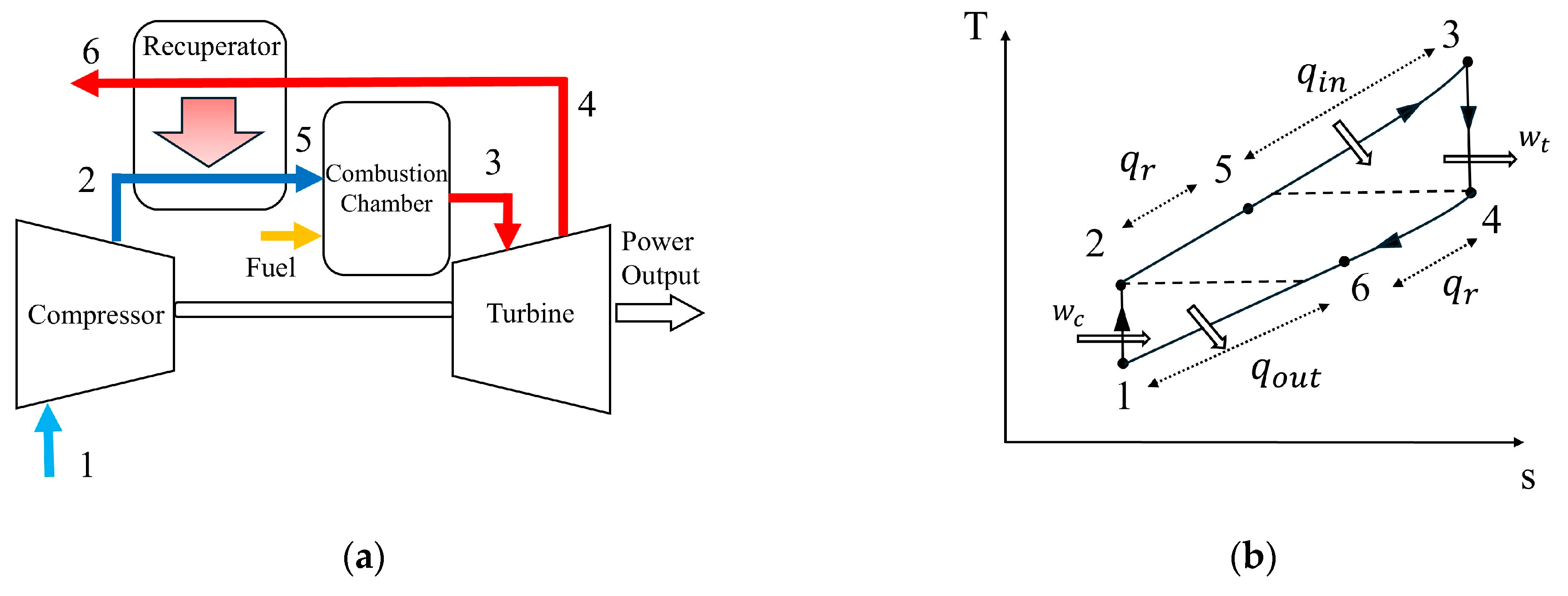
In this study, the one-dimensional (1-D) thermodynamic and mechanical modeling of a single-shaft micro gas turbine designed for range-extended electric vehicles (REEVs) was performed using Simcenter Amesim v.2504 (Siemens) software. The system generally consists of a radial compressor, a combustion chamber, a radial turbine, and a recuperator that provides heat recovery. Figure 1 shows the regenerative Brayton cycle (a) and the temperature–entropy diagram (b).
The system’s thermodynamic basis is the regenerative Brayton cycle. Air drawn from the atmosphere (1) is compressed in the radial compressor (2). Before entering the combustion chamber, the compressed air is preheated in the recuperator (2–5), a counterflow heat exchanger. The preheated air is mixed with fuel in the combustion chamber, where combustion occurs at constant pressure (5–3). The high-temperature, high-pressure combustion exhaust gases are expanded in the radial turbine to produce mechanical work (3–4). The relatively high-temperature exhaust gases existing from the turbine pass through the recuperator (4–6), transferring part of their thermal energy to the cold air from the compressor, and are then discharged into the atmosphere.
The thermal efficiency ( η t h ) of the regenerative system is given in Equation (1) [26]:
η t h = w n e t q i n = w t w c q i n = ( h 3 h 4 ) ( h 2 h 1 ) ( h 3 h 5 )
Here, w t and w c represent the specific work of the compressor and turbine, respectively. The thermal energy entering the cycle per unit mass is denoted as q i n . One of the system’s most critical thermodynamic parameters, recuperator effectiveness   ( ) , is defined by Equation (2) [27]:
= T 5 T 2 T 4 T 2
Here, T 5 represents the temperature of the air at the combustion chamber inlet after heat recovery; T 2 represents the compressor outlet temperature; T 4 represents the turbine exhaust temperature. Thanks to preheating, the amount of fuel required to reach the target Turbine Inlet Temperature (TIT- T 3 ) in the combustion chamber is significantly reduced. This ensures an increase in thermal efficiency while keeping net work constant. Turbine inlet temperature ( T 3 ) is a key design and performance variable that directly determines both specific work output and cycle thermal efficiency [28]. The upper limit of this temperature is determined by the thermal resistance of the material used in the radial turbine blades [29].
In a regenerative cycle, the total heat energy entering the system and the specific fuel consumption are calculated as follows [28]:
Q = m ˙ f L H V ,
S F C = m ˙ f P n e t = m ˙ f ( T t T c ) ω
Here, P n e t represents net power, T t represents turbine torque, T c represents compressor torque, ω represents the shaft angular velocity, LHV represents the lower heating value of the fuel, m ˙ f represents the fuel flow rate to the combustion chamber, Q represents the total heat energy supplied to the system, and SFC represents the specific fuel consumption.

2.2. Modeling of a Regenerative Micro Gas Turbine in the Simcenter Amesim Environment

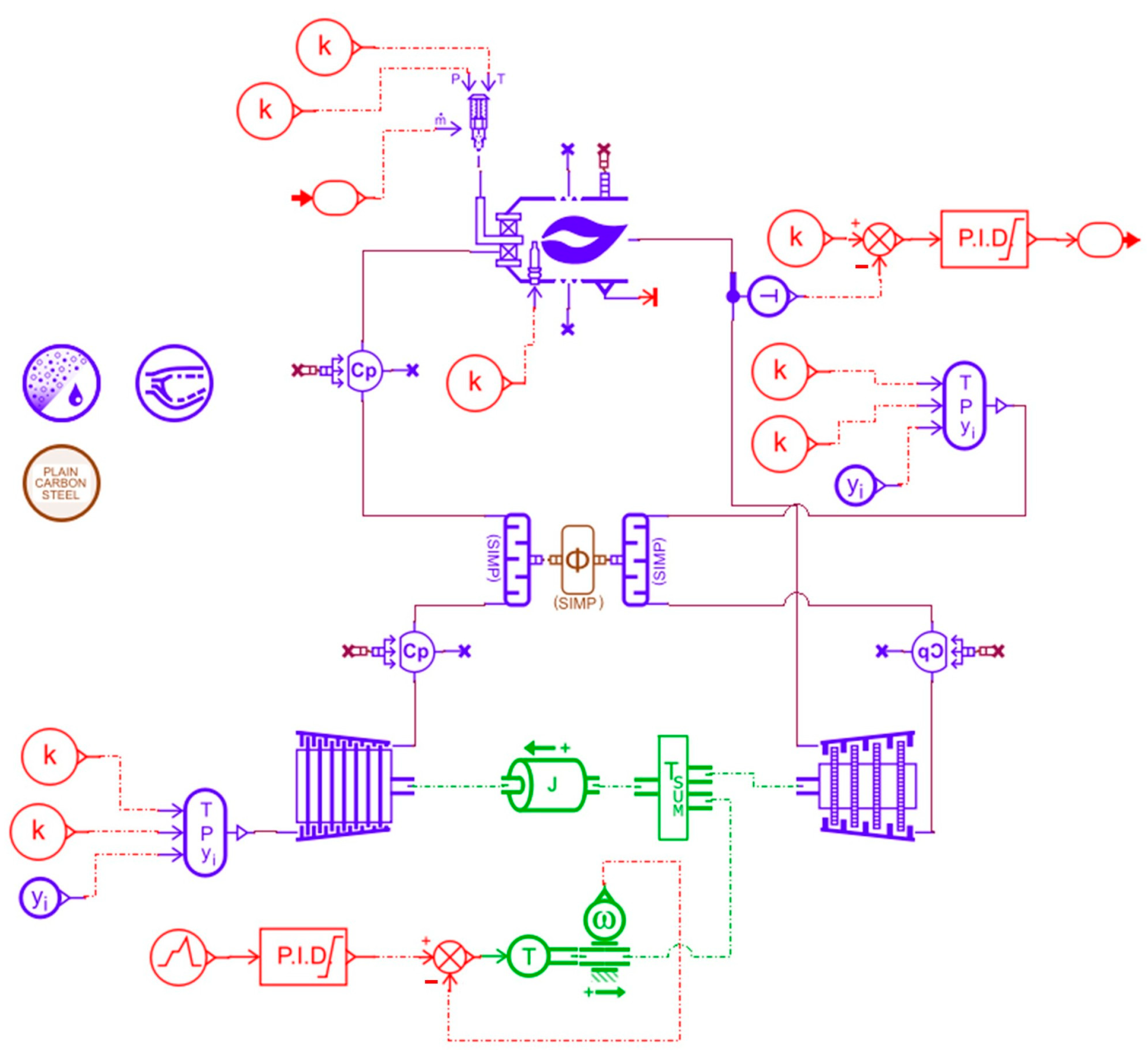
In this study, the Simcenter Amesim software was used to create a one-dimensional model of the regenerative Brayton cycle. In addition to the Amesim software’s gas turbine library, the 1-D mechanical, signal, and control libraries were used to build the model. The model created in the Amesim environment is shown in Figure 2.
In the micro gas turbine model, the gas mixture circulating in the system was first created using the gas editor in the Amesim program. Since the air in the system is drawn from the atmosphere via the compressor, the atmospheric air was modeled in three different components. These were entered into the editor as oxygen (O2), argon (Ar), and nitrogen (N2). LPG (propane-C3H8) was selected as the fuel for this study due to its compatibility with automotive applications, high energy density, and ease of storage. Carbon dioxide (CO2) and water vapor (H2O) were defined as combustion products. A total of six different species have been defined. The ideal stoichiometric complete combustion reaction occurring in the combustion chamber was introduced into the program using Amesim’s combustion editor. The air composition used in the system is given in Equation (5). The ideal complete combustion reaction occurring in the combustion chamber is defined in the Amesim library by Equation (6). The lower heating value (LHV) of LPG was taken as 46.4 MJ/kg.
Air   Composition :   0.78109   N 2 + 0.20954 O 2 + 0.00937 A r ,
C 3 H 8 + 5 O 2 3 C O 2 + 4 H 2 O .
The thermodynamic properties of all gas types defined in the system were obtained from the library included in the software’s type editor and integrated into the program using the NASA polynomial representation.
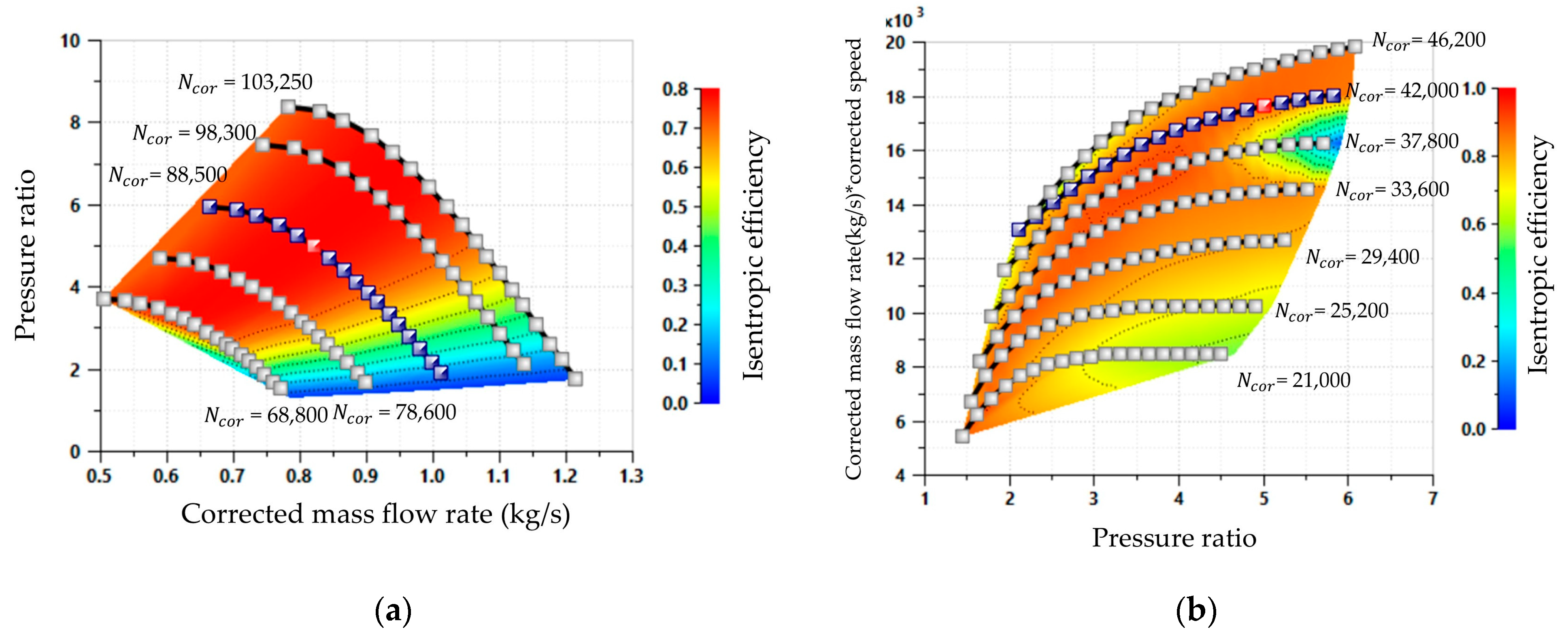
The performance characteristics of the radial compressor and turbine components used in this study were determined based on the nominal design parameters presented in Table 1. To accurately reflect the steady-state and transient performance of the compressor and turbine components, these parameters were defined as boundary conditions in the derivation of system-specific SAE performance maps under standard ISO reference conditions (288.15 K and 1.013 barA) using the Simcenter Amesim ‘Map Scaling’ tool. The performance maps of the single-stage centrifugal compressor and radial turbine used in the model are shown in Figure 3.
Characteristic performance maps were used to determine the off-design performance of the single-stage centrifugal compressor and radial turbine in the micro gas turbine model. To account for changes in inlet conditions (temperature and pressure) during transient and off-design operating conditions, the turbomachine performance maps were defined in terms of corrected parameters. For both the compressor and the turbine, the actual physical rotational speed ( N a c t u a l , rpm) and actual mass flow rate ( m ˙ a c t u a l , kg/s) are converted to corrected rotational speed ( N c o r , rpm) and corrected mass flow rate ( m ˙ c o r , kg/s) based on the specified reference conditions. The corrected rotational speed is calculated as given in Equation (7).
N a c t u a l = N c o r T u p T r e f   .
Here, T u p   (upstream temperature, K) represents the total temperature at the component inlet, while T r e f (reference temperature, K) represents the reference temperature used to generate the performance map. Similarly, the corrected mass flow rate, which balances changes in inlet temperature and pressure to maintain the continuity of the flow parameter, is defined by Equation (8):
m ˙ a c t u a l = m ˙ c o r T u p T r e f P r e f P u p .
Here, P u p   (upstream pressure, kPaA) represents the total pressure at the component inlet, while P r e f (reference pressure, kPaA) represents the reference pressure of the map. In the simulation model, these corrected values are used to interpolate steady-state performance charts to determine the instantaneous isentropic efficiency and the pressure ratio (for the compressor) or the expansion ratio (for the turbine). The reference temperature and pressure values for the performance maps used in this model are 1.013 barA and 288.15 K, respectively.
In the simulations, the model’s operational envelope was scanned between 40,000 RPM (idle/post-startup) and 100,000 RPM (full load). A PID (Proportional-Integral-Derivative) controller and a torque source were connected to the system shaft. The PID controller reads the shaft speed and generates torque to achieve the target speed. Here, when the micro gas turbine engine exceeds the speed at which it overcomes its own inertia, the same unit acts as a generator—that is, a load—absorbing the net power generated by the turbine. To overcome the turbine’s thermal inertia and ensure the recuperator reaches full thermal equilibrium at intermediate operating points, step signals with 25 s dwell times at every 10,000 RPM increment were applied to the PID controller instead of a continuous ramp signal. This method filtered out transient fluctuations, enabling the acquisition of steady-state data.
In the developed MGT model with a recuperator, a closed-loop fuel feedback control architecture was designed to maintain the system’s thermal stability under varying power demands and climatic conditions. Turbine Inlet Temperature (TIT), the most critical parameter directly affecting system performance and material durability, is monitored in real-time via a virtual thermocouple (temperature sensor) integrated into the combustion chamber outlet. The system’s fuel management is implemented through a PID control module directly indexed to TIT targets. Different target TIT values (1000 K, 1100 K, and 1250 K) are transmitted to the PID block as reference (setpoint) signals. The controller dynamically adjusts the LPG mass flow rate ( m ˙ f ) injected into the combustion chamber to minimize the error between the instantaneous temperature measured in the combustion chamber and the target reference value. To accurately reflect real-world hardware-in-the-loop limits in the model, the physical flow capacity of the fuel injector and pump was accounted for; saturation limits ranging from 0 kg/s (minimum) to 0.05 kg/s (maximum) were defined for the PID output signal.
To bring the model’s thermodynamic limits closer to real-world conditions, the mechanical, aerodynamic, and thermal losses within the system were carefully quantified based on data from the literature. The study did not use an electrical generator module; instead, a PID-controlled torque source integrated into the system shaft served as the generator load, absorbing the net mechanical power. Therefore, the power values presented represent the ‘Net Mechanical Power’ obtained under the assumption of a 99% mechanical efficiency [30], which accounts for bearing friction losses. To account for incomplete combustion in the combustion chamber and heat losses to the environment, the combustion efficiency was defined as 99% [31]. On the other hand, pressure drops caused by aerodynamic friction and geometric changes within the gas path have been dynamically modeled via aerodynamic flow coefficients on the inlet-exhaust channels and combustion chamber (swirler), rather than as fixed ratios. These coefficients have been defined to produce pressure losses within the nominal range of 3% to 4% [31], which is widely accepted in the literature for MGTs at the design point. These refined loss parameters integrated into the system ensure that the net power and specific fuel consumption (SFC) estimated through simulation represent MGT performance as closely as possible to physical reality.
A comprehensive parametric simulation study was designed to examine the thermodynamic responses of the MGT’s REEV concept across a full spectrum of driving and climate scenarios. The system was tested across the operational range from 40,000 to 100,000 rpm under three different extreme climate conditions: winter (−10 °C/263.15 K), standard day (20 °C/293.15 K), and summer (45 °C/318.15 K). In addition to these environmental factors, three different recuperator effectiveness settings ( : 0.75, 0.85, and 0.95) and three different Turbine Inlet Temperatures (TIT: 1000 K, 1100 K, and 1250 K), which define the MGT’s maximum thermal limits, were parametrically scanned. This established multidimensional test matrix aims to numerically demonstrate not only the MGT’s power and fuel consumption characteristics, but also the usability of the exhaust gas discharged from the recuperator for vehicle cabin heating (WHR) under winter conditions of −10 °C.
In 1-D analyses performed using Simcenter Amesim software, the solution procedure and simulation algorithm followed by the system from the initial condition until it reaches the steady-state operating point consist of the following steps:
Step 1—Initial Conditions: The ambient temperature (−10/20/45 °C), atmospheric pressure, target turbine inlet temperature (TIT), and recuperator effectiveness values ( ) are defined in the solver.
Step 2—Map Scaling: Compressor and turbine performance maps are scaled to reference values based on the design point mass flow rate and pressure ratios.
Step 3—PID Control and Loading: The PID controller integrated into the shaft regulates the speed between 40,000 RPM (idle) and 100,000 RPM (full load) to scan the operating envelope; when the system exceeds its own inertia, the PID acts as a generator (load) that draws net power.
Step 4—Stepped Solving: To dampen thermal inertia, dynamic solving is performed by applying stepped signals with a 25 s dwell time for every 10,000 RPM increase, rather than a continuous ramp signal.
Step 5—Reaching Steady State: During the 25 s waiting periods, transient fluctuations are completely filtered out, ensuring that the entire system—including the recuperator—reaches full thermal equilibrium.
Step 6—Data Extraction: Once the system has become stable, the net mechanical power, thermal efficiency, SFC, and specific CO2 emission values are recorded.

3. Model Validation

In this study, the performance of the MGT system was analyzed using one-dimensional (1-D) thermodynamic and mechanical modeling methods. Although the flow in micro-scale turbomachinery is known to be highly three-dimensional (3D) in nature and involves complex boundary layer interactions, 1-D system-level modeling enables a comprehensive operational envelope scan under extreme climatic conditions and variable design parameters by minimizing computational costs. In this approach, aerodynamic losses resulting from 3D flow physics have been incorporated into the model using performance maps and loss coefficients based on experimental data.
The thermodynamic and dynamic consistency of the one-dimensional (1-D) MGT system model developed in this study was verified using experimental data from the study by Ji et al. [17] published in the literature. The parameters used temporarily to validate the simulation model experimentally (air flow rate, 0.11 kg/s; compressor and turbine efficiencies, 0.85 and 0.82, respectively; pressure ratio, 3.2; recuperator effectiveness, 0.6; shaft speed, 100,000 rpm) were taken from the study by Ji et al. [17]. Using these parameters, compressor and turbine maps were generated using the Simcenter Amesim ‘Map Scaling’ tool. In the experiment conducted by Ji et al. [17], diesel was used as fuel. For the simulation model, a temporary fuel definition was created using the fuel editor to replace LPG with diesel. The ideal complete combustion reaction occurring in the combustion chamber is defined in the Amesim library by Equation (9). The lower heating value (LHV) of diesel was taken as 42,079 kJ/kg.
C 12 H 26 + 18.5 O 2 12 C O 2 + 13 H 2 O .
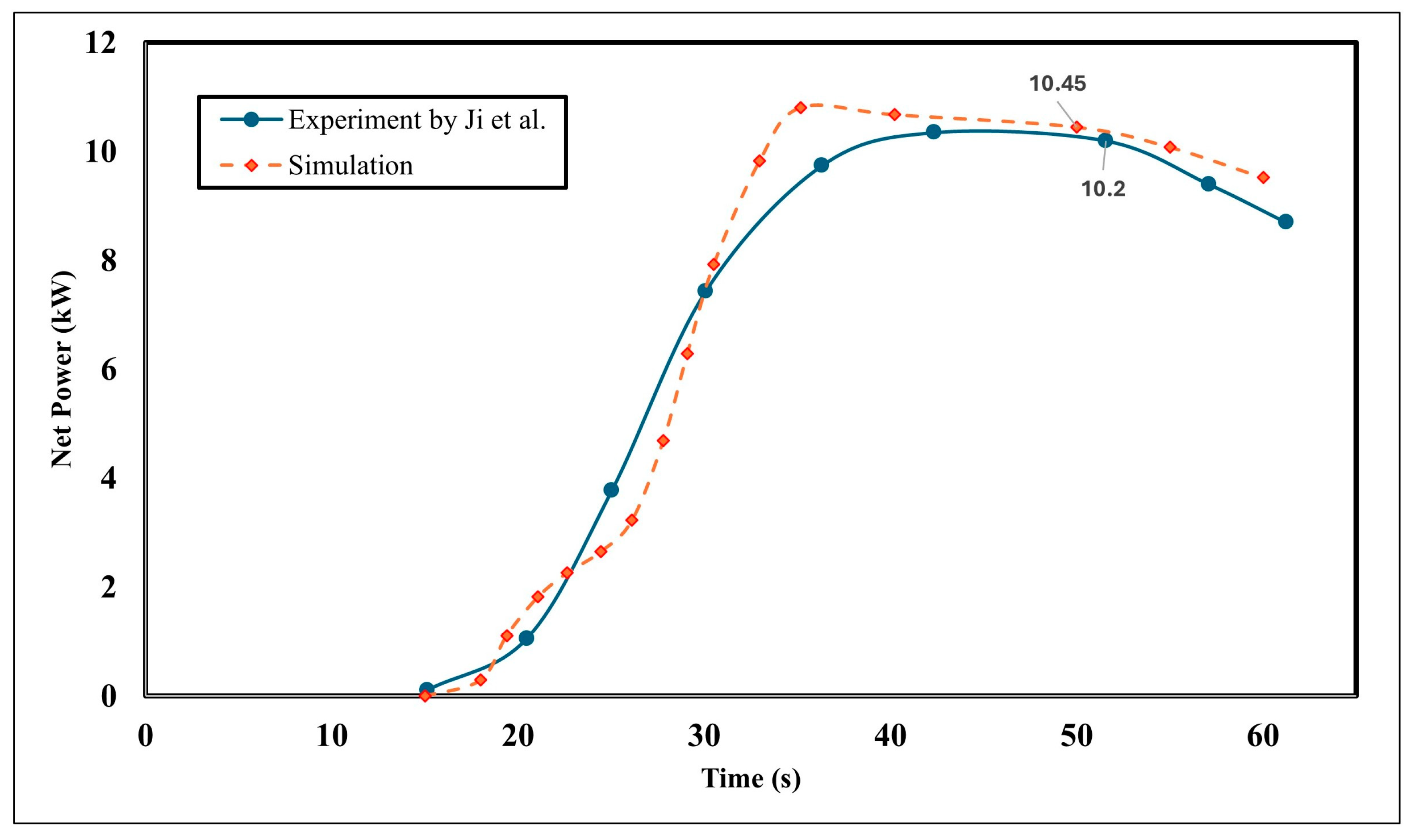
For dynamic validation analysis, the physical startup procedure defined by Ji et al. [17] was applied. In the model, the shaft was first brought to a speed of 1500 rpm using a PID controller, and then fuel injection into the combustion chamber was initiated. When the shaft speed reached 5000 rpm, external motor support was disengaged, and the system was accelerated sharply to the design speed (100,000 rpm) using the turbine power it generated. Figure 4 shows the time-dependent variation in the net power output obtained from the simulation. As can be seen, the model’s takeoff dynamics are in good agreement with the experimental curves in the reference study [17].
Once the system reached a steady state, the net output power was determined to be 10.2 kW based on the experimental data. Furthermore, in the experiments conducted by Ji et al. [17], it was reported that this net output power was achieved at a shaft speed of 100,000 rpm and a turbine inlet temperature of 1090 K. As shown in Figure 4, the Amesim simulation resulted in a net power of 10.45 kW. Furthermore, according to the simulation results, a turbine inlet temperature of 991.89 K and a shaft speed of 99,000 rpm were obtained at a net power output of 10.45 kW. The differences between simulation and experimental results in terms of shaft speed, TIT, and output power are approximately 1%, 9.89%, and 2.45%, respectively. These deviation rates stem from the structural differences between the specific 3D laboratory prototype in the reference study (local flow boundaries, friction, etc.) and the aerodynamic loss characteristics of the generic SAE turbomachinery performance maps used in 1-D system-level analyses. In conclusion, the thermodynamic validation of the MGT concept using the 1-D model established in Simcenter Amesim was performed, and it was demonstrated that the model is consistent with the literature. Following this validation phase, the model was scaled to the original design targets, and parametric analyses were conducted.

4. Results and Discussion

In this section, the findings obtained from the parametric simulation results are presented and discussed. The thermodynamic responses of the developed micro gas turbine (MGT) under different climate conditions, recuperator effectiveness values, and turbine inlet temperatures (TITs) are presented in terms of the system’s net power output, maximum thermal efficiency, specific fuel consumption (SFC), and mass CO2 emissions. The findings reveal the system’s steady-state operational dynamics, and particularly the potential for waste heat recovery (WHR) to be used for vehicle cabin heating during winter months.

4.1. Thermal Efficiency Characteristics of a Micro Gas Turbine

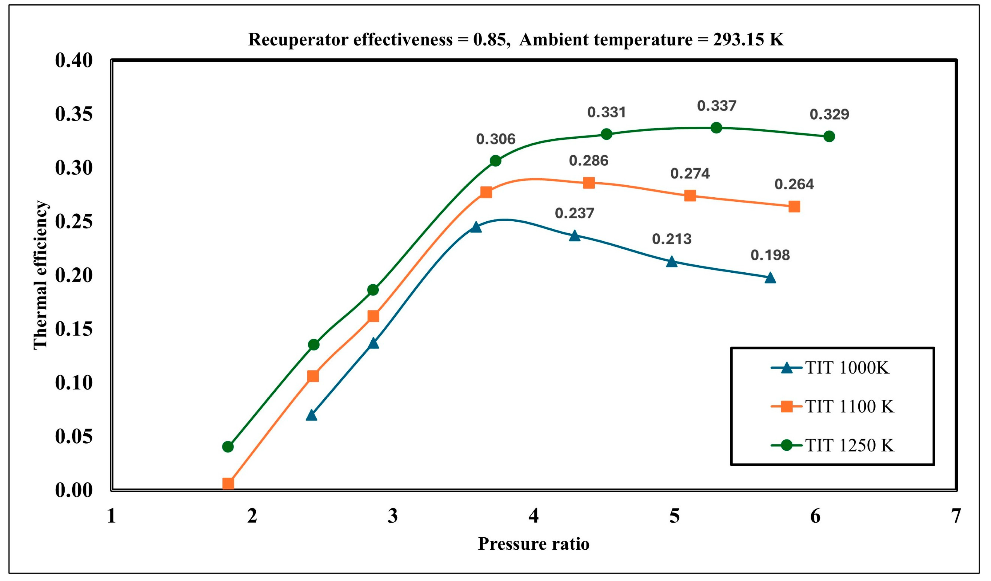
The most fundamental thermodynamic factors limiting the performance of micro gas turbine (MGT) systems are the compressor pressure ratio ( r p ) and the turbine inlet temperature (TIT) [28]. To validate the thermodynamics of the developed 1-D model and determine the system’s operational capacity limits, thermal efficiency curves obtained under standard ambient conditions (293.15 K) and at a constant recuperator effectiveness of 0.85 are presented in Figure 4.
Examining Figure 5, it can be seen that an increase in the TIT value significantly boosts thermal efficiency up to certain pressure ratios. Specifically, at a turbine inlet temperature of 1000 K, the maximum thermal efficiency reached 0.245 at a pressure ratio of 3.59; at 1100 K, it reached 0.286 at a pressure ratio of 4.39; at 1250 K, it reached 0.337 at a pressure ratio of 5.3. The most critical thermodynamic behavior highlighted in Figure 5 is the shift in the optimal pressure ratio—at which maximum efficiency is achieved—toward higher values (to the right) as the TIT increases. This phenomenon is explained by the need for a higher expansion ratio in the turbine as the enthalpy of the gas out the combustion chamber increases.
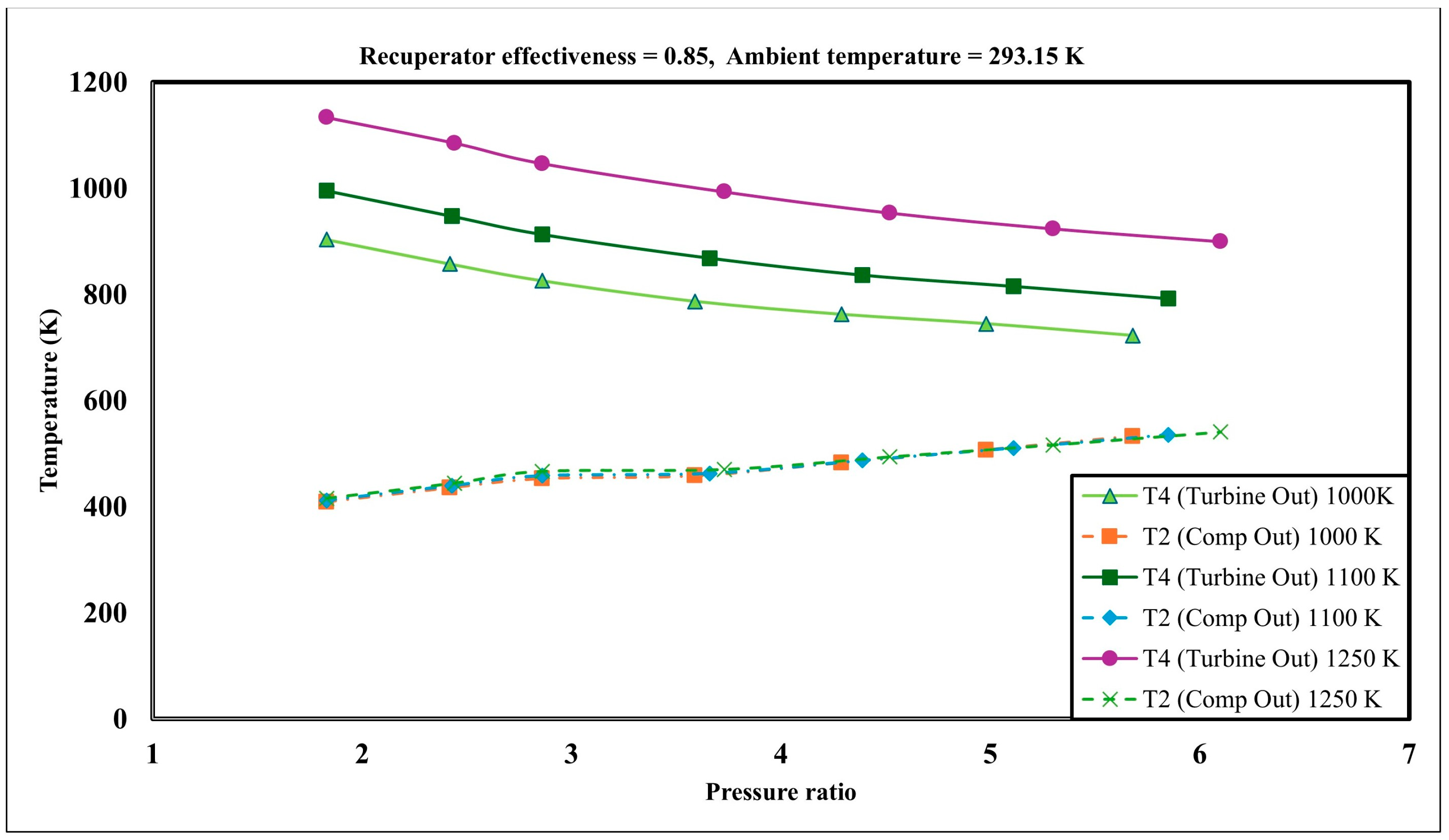
However, as shown in Figure 5, thermal efficiency drops rapidly beyond the optimal pressure ratio. According to the results of temperature simulations conducted to determine the system’s thermodynamic limits (Figure 6), for TIT 1000 K, at low pressure ratios, the difference between the turbine outlet temperature and the compressor outlet temperature is 494 K; however, when the pressure ratio reaches 5.68, T2 rises to 532.8 K, while T4 drops to 722.8 K. For TIT 1250 K, at a pressure ratio of 6, T2 rises to 541 K, while T4 drops to 900 K. This narrowing temperature difference (ΔT) between the two gases limits the recuperator’s heat transfer potential. At high pressure ratios, the decrease in the recuperator’s preheating capacity necessitates sending a higher mass flow rate of fuel to the combustion chamber to maintain the target TIT value, which in turn leads to a dramatic drop in thermal efficiency. Furthermore, increasing the pressure ratio further complicates the design of a single-stage compact compressor and increases the system’s physical dimensions and cost. Therefore, considering thermodynamic convergence limits and physical constraints, the 5.0–6.5 pressure ratio range has been determined as the optimal operating point based on the simulation results. These findings are consistent with experimental studies by Ji et al. [17], which indicate that the optimal pressure ratio for a regenerative micro gas turbine cycle typically ranges from 4 to 6.

4.2. The Effect of Recuperator Effectiveness on MGT Performance

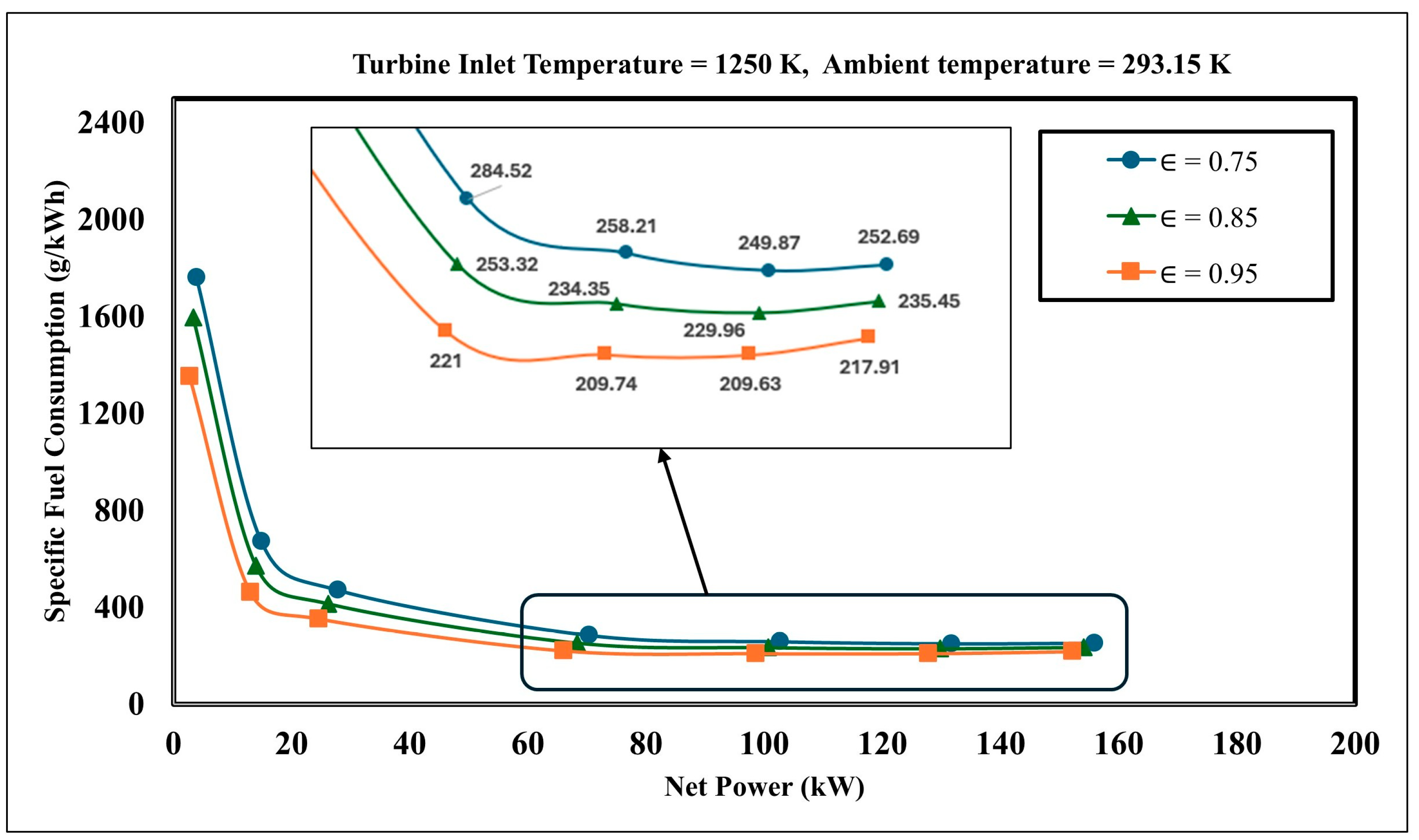
The key metric determining the commercial and operational feasibility of the auxiliary power unit (APU) in range-extended electric vehicles (REEVs) is Specific Fuel Consumption (SFC), which represents the amount of fuel consumed per unit of electrical energy transferred to the battery. As shown in Figure 5, thermal efficiency increases at high turbine inlet temperatures. The MGT performance values presented in this section are given at a turbine inlet temperature of 1250 K and a standard ambient temperature of 293.15 K. The cumulative effects of different recuperator effectiveness values ( : 0.75, 0.85, and 0.95) on fuel economy and net power output in the developed MGT system are presented in Figure 7.
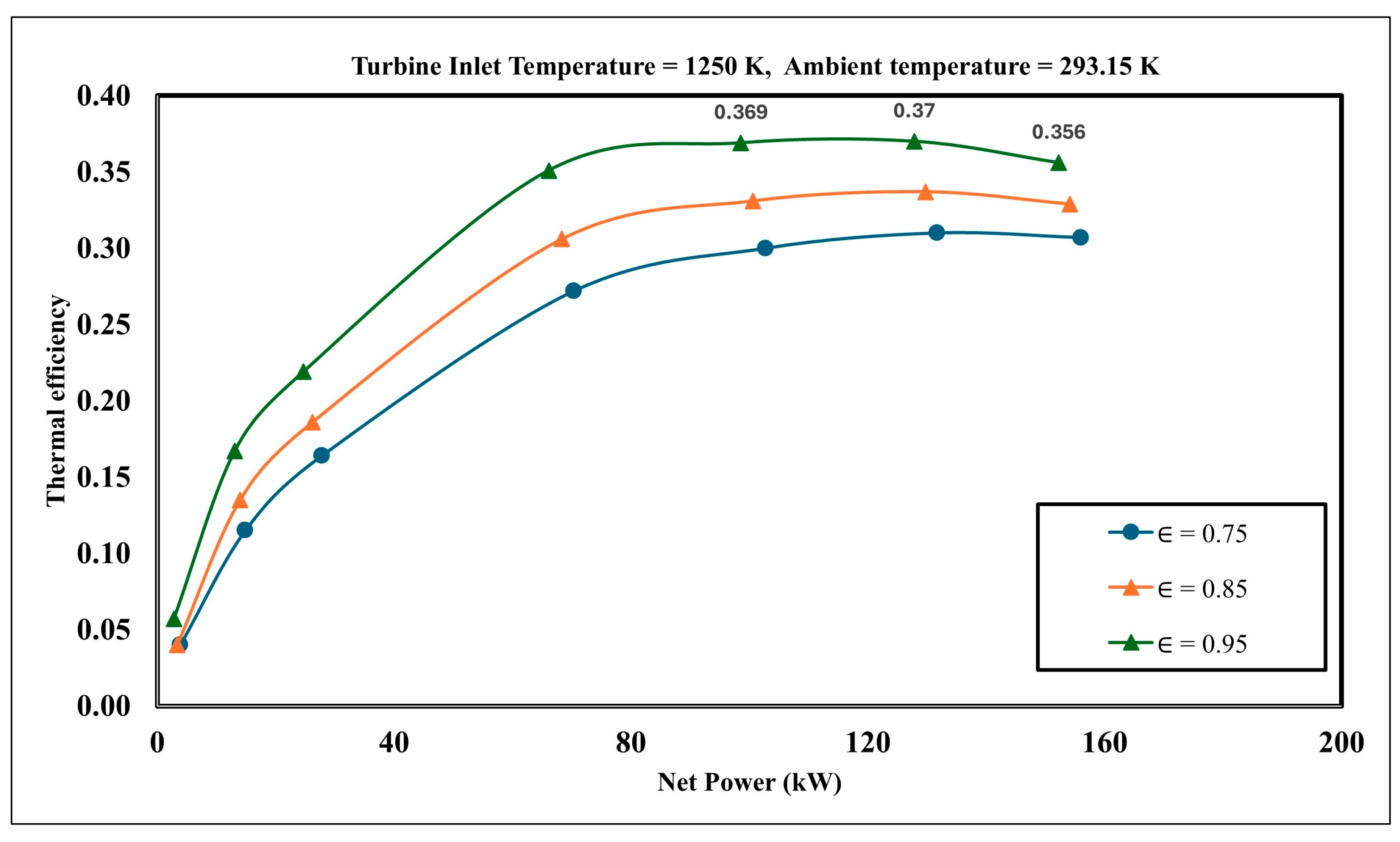
The simulation results show that as the net power generated during steady-state operation of the MGT increases (as the shaft speed approaches 100,000 RPM), the SFC value improves exponentially. The high SFC values, a characteristic issue of simple-cycle MGTs without a regenerator, have been eliminated in this study through the application of high-efficiency heat recovery. As shown in Figure 7, even in a basic recuperation scenario with an effectiveness of = 0.75, the minimum SFC was achieved in the range of 249.87 g/kWh. Figure 8 presents the net power curves for thermal efficiency at a turbine inlet temperature of 1250 K. It was determined that a maximum thermal efficiency of 0.37 was achieved at a net power value of 127.82 kW when the recuperator effectiveness was 0.95. As seen in Figure 7, the specific fuel consumption reached a minimum of 209.63 g/kWh at a net power of 127.82 kW.
When compared to similar studies in the literature, Ji et al. [17] reported the lowest SFC of 266 g/kWh in a 10 kW MGT system with an efficiency of 0.7. Shah et al. [22], on the other hand, experimentally observed that SFC values reached up to 398 g/kWh in a 25 kW dynamic MGT concept. It is known that conventional diesel-powered range extenders (ICEREs) have an average specific fuel consumption in the range of 220–250 g/kWh [10,11]. These findings indicate that micro gas turbines could serve as a competitive alternative solution for fuel economy in automotive applications.

4.3. The Effect of Different Climate Conditions on MGT Performance

The performance of Micro Gas Turbines (MGTs) is highly sensitive to the ambient temperature and the air density at the compressor inlet. To test the reliability of the developed LPG-fueled MGT range extender with a recuperator under various geographical and seasonal conditions, simulations were conducted under three different ambient temperature scenarios: winter (−10 °C/263.15 K), standard day (20 °C/293. 15 K), and summer (45 °C/318.15 K).
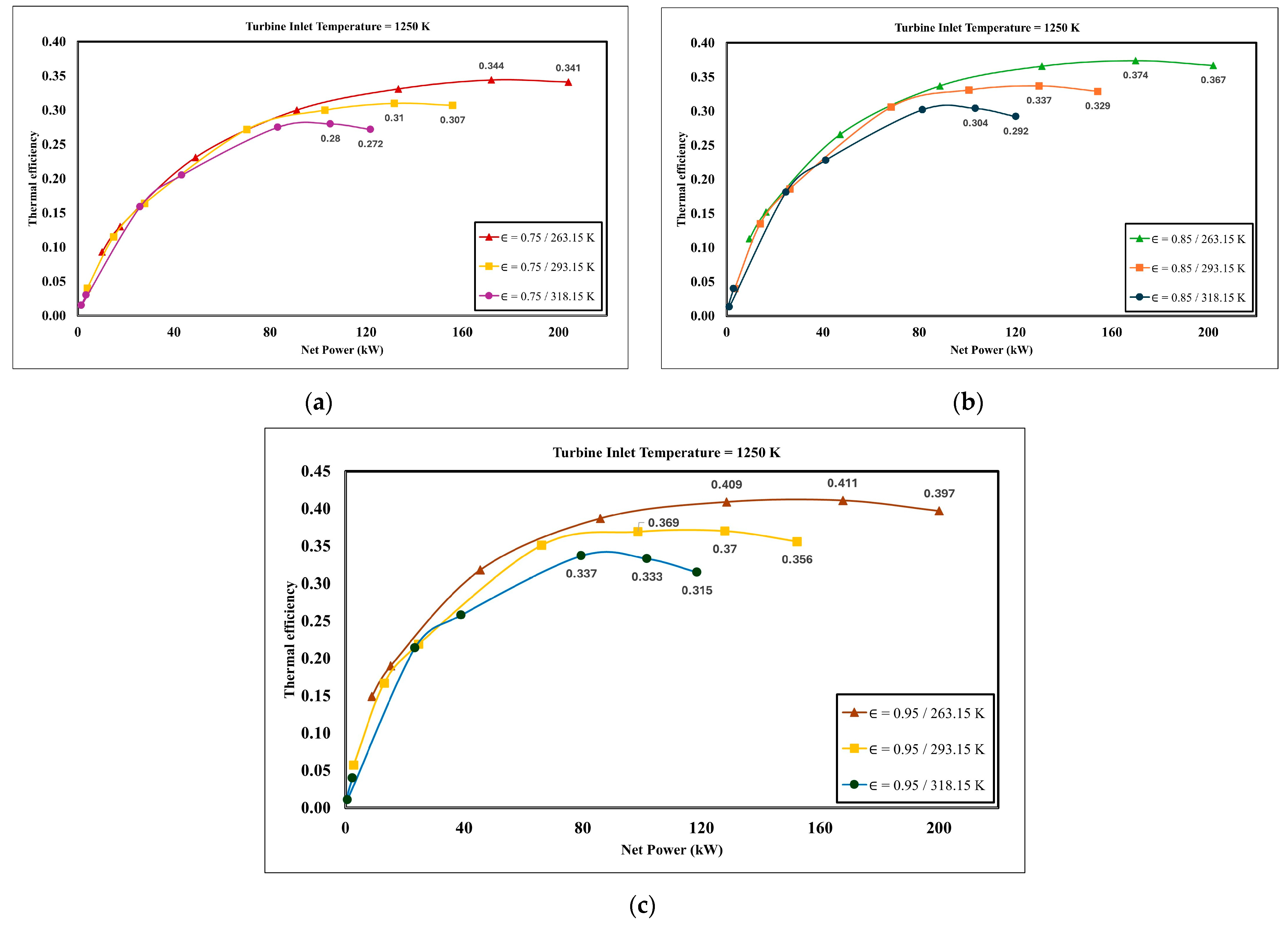
Figure 9a–c show the thermal efficiency–net power curves under three different climate conditions, with recuperator effectiveness values of 0.75, 0.85, and 0.95, respectively. The system achieved a net power of 167.57 kW and a thermal efficiency of 41.1% under winter conditions (−10 °C/263.15 K), with a Turbine Inlet Temperature (TIT) of 1250 K and a recuperator effectiveness of 0.95. This is due to the decrease in specific volume and increase in the density of air at low ambient temperatures. This situation ensures an increase in the mass flow rate of air entering the system, even if the volumetric capacity of the MGT compressor remains constant. Furthermore, a decrease in the compressor inlet temperature (T1) directly reduces the specific compressor work ( ω c ) required to compress the air. However, in the hot air scenario (45 °C/318.15 K), the cycle dynamics operate in the opposite manner. Rising ambient temperature reduces air density, thereby decreasing mass flow rate. While the amount of work the compressor must expend to achieve the target pressure ratios increases, the net work ( ω n e t ) obtained from the turbine decreases. Table 2 presents the air flow rates out of the compressor, compressor powers, and specific work at a 0.95 recuperator effectiveness at different ambient temperatures.
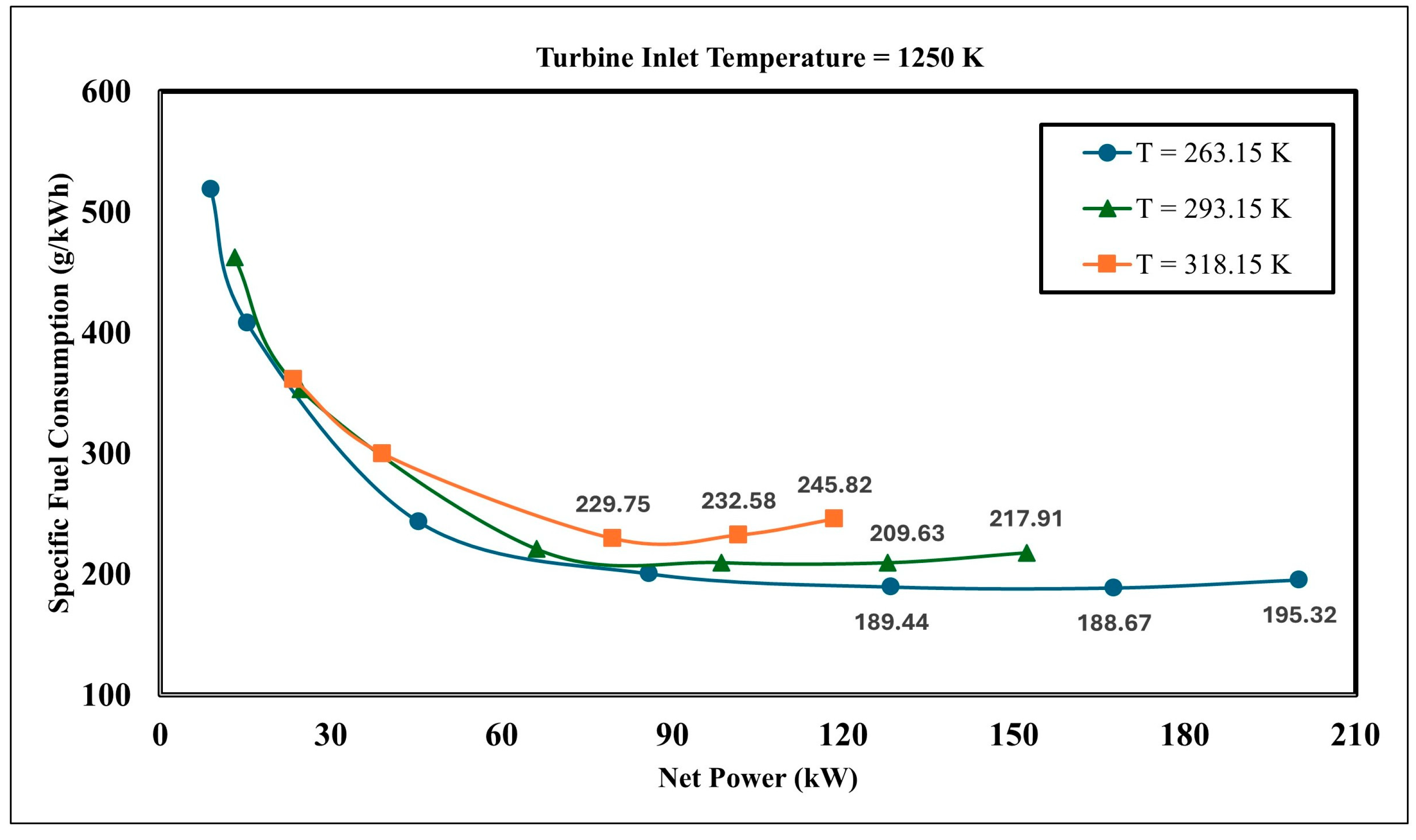
The heating of the air also reduces the heat transfer potential in the recuperator, negatively affecting the system’s thermal efficiency and leading to increases in SFC values. In this context, Figure 10 shows the SFC–net power curves at different ambient temperatures with a 0.95 recuperator effectiveness. The system achieved its highest performance under winter conditions at −10 °C (263.15 K), with a Turbine Inlet Temperature (TIT) of 1250 K and a 0.95 recuperator effectiveness.
At this ideal operating point, the system achieved a net power output of 167.57 kW, a thermal efficiency of 41.1%, and a specific fuel consumption (SFC) of 188.67 g/kWh. This clearly demonstrates that cold climates maximize the net power output and thermal efficiency of the MGT cycle. These findings point to a critical strategic advantage for electric vehicle (EV) technologies. Current lithium-ion battery technologies experience dramatic capacity and range losses of 30% to 40% under cold weather conditions such as −10 °C due to increased internal resistance and slowed electrochemical reactions [32,33,34]. In this winter scenario, where batteries are at their weakest, the proposed MGT concept achieves 41.1% thermal efficiency and reduces fuel consumption to 188.67 g/kWh. By turning the cold-weather disadvantage of batteries into a thermodynamic advantage, the MGT demonstrates that it is a competitive auxiliary power unit (APU) for range-extended electric vehicles (REEVs).
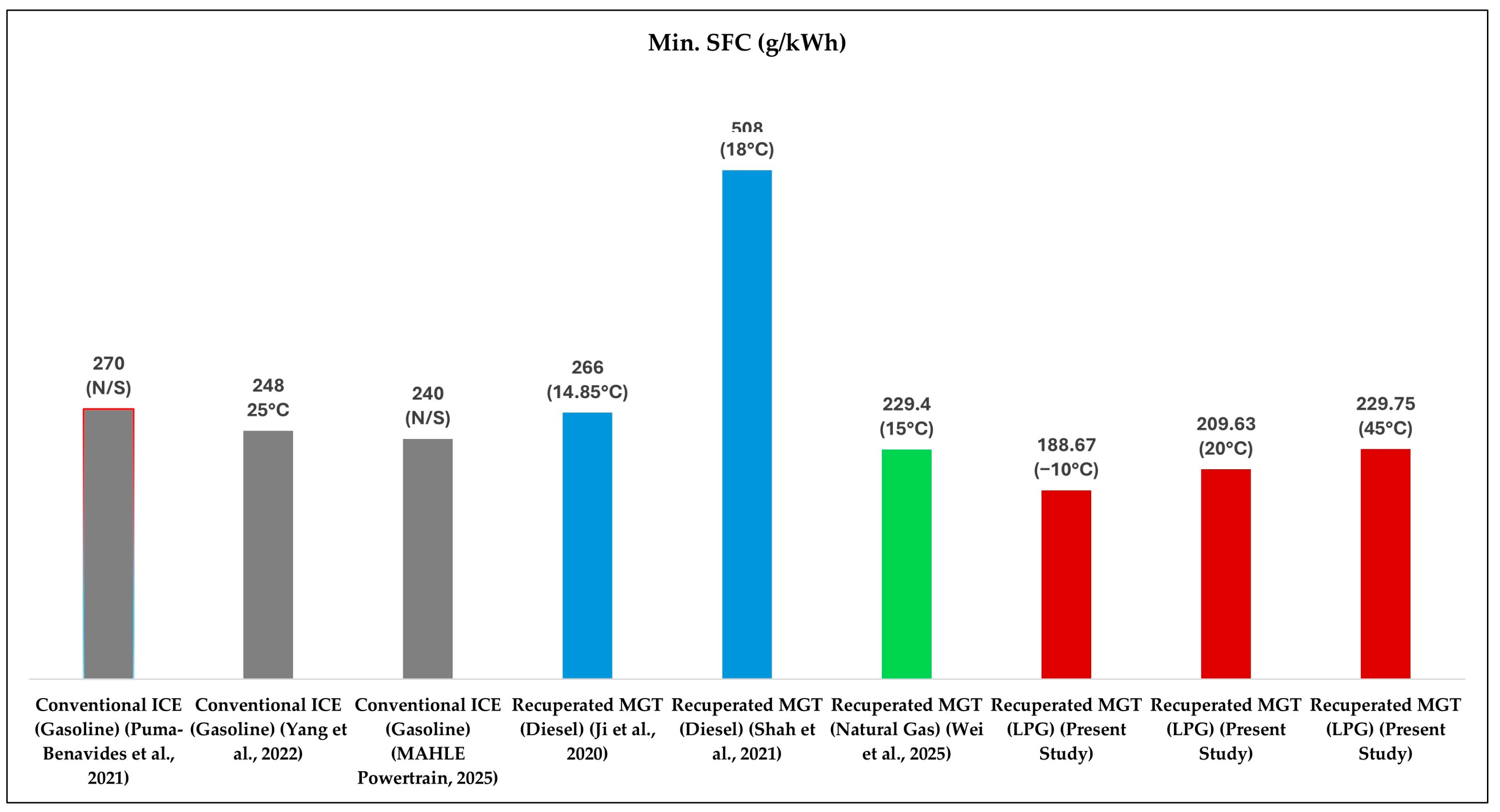
The performance of the proposed LPG-fueled MGT power unit is presented in Table 3 in comparison with existing range-extender technologies under various climate conditions. Additionally, Figure 11 compares the minimum specific fuel consumption (SFC) values obtained from the current study with those of baseline gasoline internal combustion engines and commercial MGT systems operating on different fuels (diesel, natural gas).
An examination of Table 3 and Figure 11 reveals that the minimum specific fuel consumption (SFC) values for conventional gasoline internal combustion engine (ICE) range extenders fall within the range of 240 to 270 g/kWh [2,11,35]. Similarly, other recuperative micro gas turbine (MGT) systems fueled by diesel and natural gas in the literature exhibit a much wider range of SFC values, varying between 229.4 and 508 g/kWh [17,20,21]. In contrast, the recuperated LPG-MGT system simulated in this study demonstrated a clear thermodynamic advantage over baseline technologies at all ambient temperatures examined. The proposed power unit achieved a SFC of 209.63 g/kWh and a thermal efficiency of 37% at a nominal ambient temperature of 293.15 K (20 °C), while maintaining SFC and thermal efficiency values of 229.75 g/kWh and 33.7%, respectively, even under extreme temperature conditions of 318.15 K (45 °C). In particular, the system’s performance reached its peak under extreme cold climate conditions at 263.15 K (−10 °C), where battery electrochemical performance and range dropped significantly; a minimum SFC value as low as 188.67 g/kWh, a net mechanical power output of 167.57 kW, and a peak thermal efficiency of 41.1% were achieved. This competitive improvement in performance is a direct result of the increased air density at low ambient temperatures positively affecting the compressor suction flow rate, as well as the high energy density of LPG, the stability of continuous combustion, and the highly efficient (95%) recovery of waste heat from the turbine exhaust into the system via a recuperator.

4.4. Environmental Impact, CO2 Emissions, and Waste Heat Recovery (WHR) Potential

Range extenders (REs) developed for range-extended electric vehicles (REEVs) must not only provide high thermal efficiency and power in the automotive market, but also have the potential for low carbon emissions. In this context, the environmental performance of the developed LPG-fueled MGT system with a recuperator was evaluated based on specific carbon dioxide (CO2) emissions and exhaust gas temperature parameters.
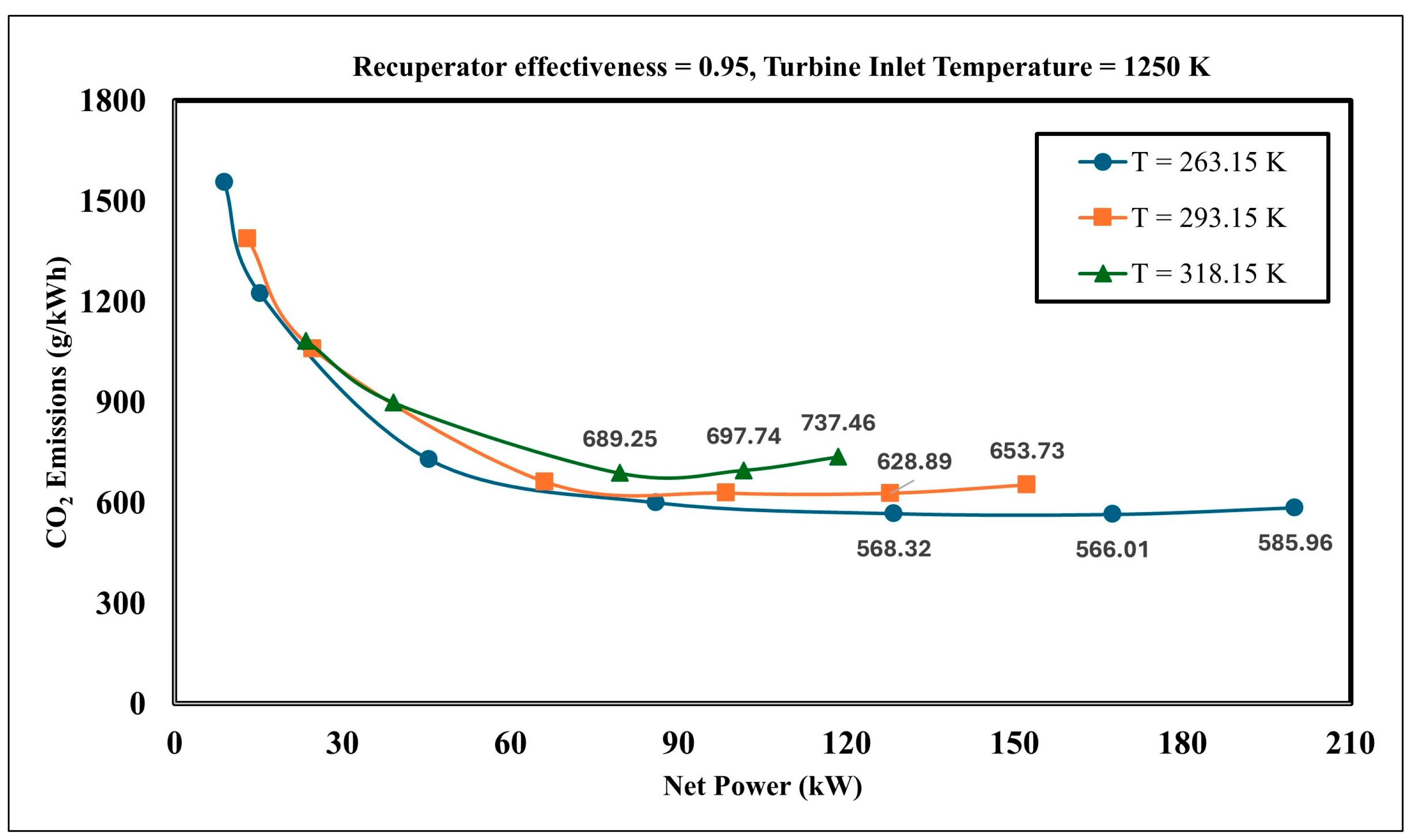
Figure 12 shows the CO2 emission–net power curves for extreme climate conditions. According to the simulation results, the low SFC value of 188.67 g/kWh achieved under the scenario of −10 °C ambient temperature, 1250 K TIT, and 0.95 recuperator efficiency—where the system operates most efficiently—directly impacted CO2 emissions. At this ideal operating point, specific CO2 emissions have been reduced to 566.01 g/kWh.
An examination of the thermodynamic behavior of the curves in Figure 12 reveals that ambient temperature has a direct and significant effect on both the system’s power output and its environmental performance. When the ambient temperature drops from 45 °C to −10 °C, the primary physical reason for the sharp increase observed in the net power curve is the increase in air density. The increased density in cold air maximizes the mass flow rate drawn into the compressor, thereby increasing the net mechanical power produced by the system (Table 2). The primary mechanism behind the decrease in specific emissions as power increases is that the recuperator, with 95% efficiency, preheats the air entering the combustion chamber to high temperatures, thereby increasing the MGT’s overall thermal efficiency. Since the net power increase is more dominant than the increase in fuel mass consumed, the amount of carbon emitted into the atmosphere per kilowatt-hour decreases. Conversely, at high ambient temperatures such as 45 °C, the air becomes less dense, the system’s thermal efficiency decreases relatively, and since a higher specific fuel consumption is required to achieve the same power, the CO2 curves in Figure 12 shift upward. These physical interactions demonstrate that the system exhibits thermodynamically environmentally friendly characteristics under extreme cold conditions.
To evaluate the environmental performance of the proposed LPG-MGT system with a recuperator, the specific CO2 emission value obtained (566.01 g/kWh) was compared with studies in the literature and summarized in Table 4.
When specific emissions (g/kWh) at the power-unit level are considered, the system modeled in this study outperforms the commercial Turbec AE-T100 (660 g/kWh) and Capstone C65 (707.14 g/kWh) micro gas turbines, which operate on natural gas (NG)-powered commercial Turbec AE-T100 (660 g/kWh) and Capstone C65 (707.14 g/kWh) micro gas turbines. This advantage is a direct result of the favorable hydrogen-to-carbon ratio in the chemical structure of LPG, as well as the peak thermal efficiency of 41.1% achieved through high recuperator efficiency under extreme cold climate conditions (−10 °C). High thermal efficiency has minimized the amount of fuel required to produce the same kilowatt-hour of energy, thereby reducing emissions to a competitive level. Although the mathematical conversion between g/kWh and g/km varies depending on vehicle dynamics parameters, minimizing specific emissions from the powertrain is the key thermodynamic parameter that drives the total operational emissions intensity (g/km) of the range-extender system downward in a linear trend. Although hydrogen PEM fuel cells represent the ultimate environmental goal by offering zero tailpipe emissions, given the current limitations of hydrogen storage and refueling infrastructure, this LPG-powered MGT configuration with a recuperator provides a currently viable, compact, and vibration-free low-carbon transition technology (bridge technology) for range-extended electric vehicles compared to internal combustion engines.
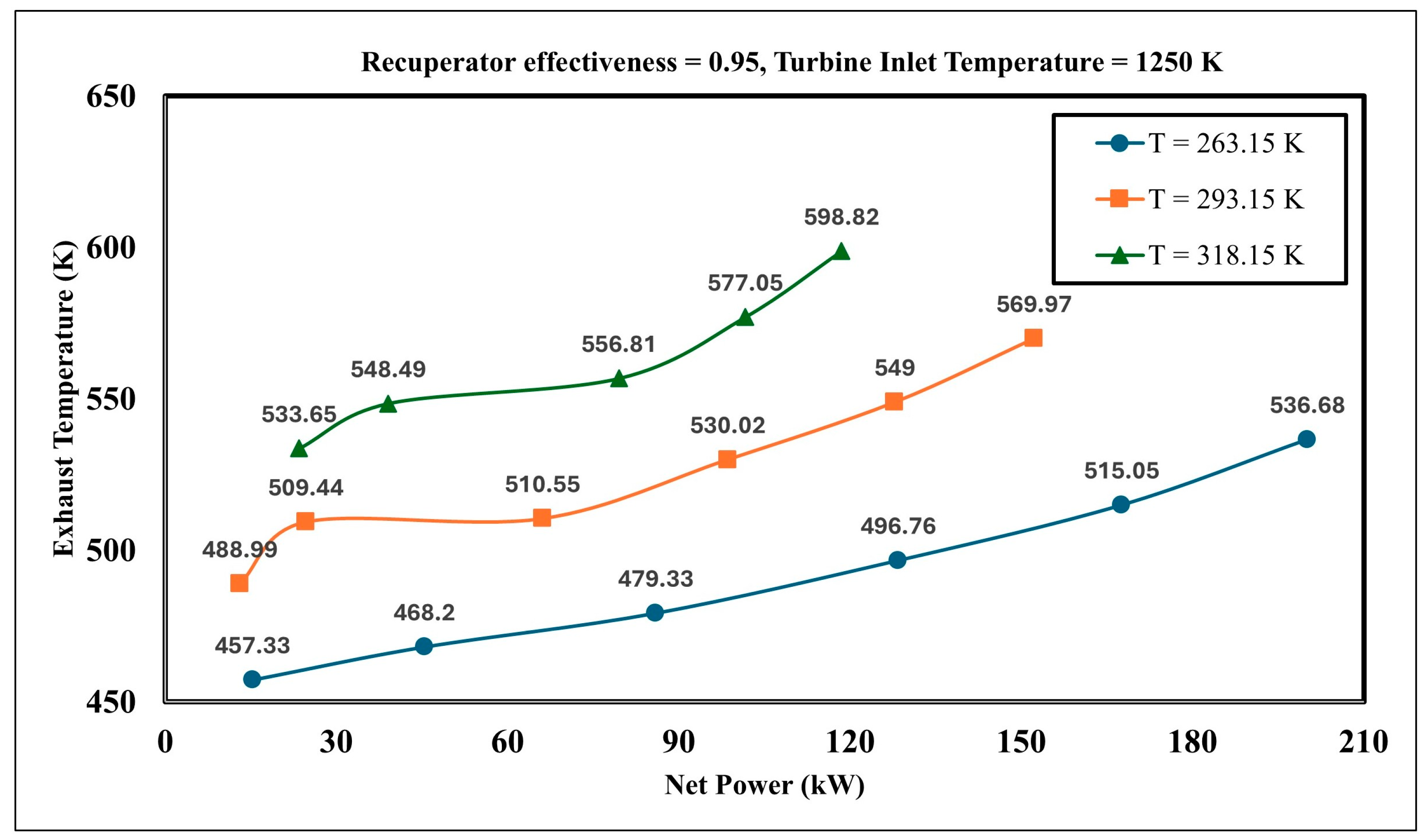
Figure 13 shows the exhaust temperature–net power curves under extreme climate conditions. Under extreme hot climate conditions (45 °C/318.15 K), due to the decrease in air density, the net mechanical power drops to 118.48 kW while the exhaust gas temperature reaches 598.82 K. Under standard climate conditions (20 °C/293.15 K), the exhaust temperature was measured at 569.97 K at a net power value of 152.22 kW. Under extremely cold climate conditions (−10 °C/263.15 K), the lowest exhaust temperature of 536.68 K was observed at a net power value of 200.11 kW. When the system operates at its ideal point with a thermal efficiency of 41.1% and a net power output of 167.57 kW, the exhaust gas temperature is determined to be 515.05 K. The exhaust temperatures shown in Figure 13 present a strategic opportunity for a waste heat recovery (WHR) system to be integrated into range-extended electric vehicles. In cold climate conditions, the use of electric heaters for battery heating and cabin climate control significantly reduces EV range. Under cold climate conditions (−10 °C), even though the exhaust temperature drops to 515.05 K at the system’s efficient operating point, this temperature level is sufficient for cabin heating and battery thermal management. In this context, the proposed MGT system, when integrated with a secondary waste heat recovery system, has the potential to transform into a combined heat and power (CHP) system that not only serves as an auxiliary power unit to charge the battery, but also heats both the cabin and the battery.

5. Conclusions

In this study, the performance of a recuperator-equipped LPG-fueled Micro Gas Turbine (MGT) used as a range extender for electric vehicles was investigated under extreme climate conditions through a parametric simulation study. The simulation results revealed the critical dependence of micro gas turbine performance on ambient temperature, recuperator effectiveness, and turbine inlet temperature (TIT). The key findings of this study are summarized as follows:
  • The MGT system demonstrated its highest performance values in cold environments (−10 °C/263.15 K). In cold climate conditions, increased air density leads to a rise in mass flow rate and a direct decrease in specific compressor work. At the optimal design point (TIT = 1250 K, recuperator effectiveness = 0.95), the system achieved a maximum thermal efficiency of 41.1% and a minimum specific fuel consumption (SFC) of 188.67 g/kWh.
  • A high-efficiency LPG-fueled micro gas turbine equipped with a recuperator achieved a low specific CO2 emission value of 566.01 g/kWh at its optimal operating point and under cold climate conditions. On the other hand, under extremely cold climate conditions (−10 °C) at the most efficient design point, the 515.05 K exhaust temperature produced by the micro gas turbine offers a significant advantage for cabin heating and battery thermal management.
An examination of the physical and thermodynamic basis of the numerical results reveals that the system’s ability to maintain performance even in extremely cold climates (−10 °C) is directly linked to the critical role of the recuperator. Although the increased fluid density in cold air increases the compressor’s workload, the recovery of high-energy waste heat from the turbine exhaust into the system with 95% effectiveness ensured thermodynamic balance and minimized fuel consumption. In contrast to traditional gasoline internal combustion engine (ICE) range extenders (240–270 g/kWh SFC range) and diesel MGTs reported in previous studies (Table 3), this study achieved a significantly lower SFC of 188.67 g/kWh. The physical basis for this advantageous numerical behavior lies in the combination of the MGT’s continuous combustion stability with LPG’s high energy density and favorable H/C (Hydrogen/Carbon) ratio, which maximizes combustion efficiency. Ultimately, these physical phenomena demonstrate that the LPG-fueled MGT with a recuperator offers a competitive and compelling range extender (RE) solution by maintaining its thermal efficiency (41.1%) and low emission profile even under cold climate conditions, where battery performance declines.
In this context, the presented study offers an innovative engineering solution in the field of applied sciences and sustainable transportation technologies by proposing a low-carbon, scalable, and highly competitive range extender concept compared to its conventional counterparts, addressing the range anxiety and thermal management problems faced by the automotive industry.
As part of future work, we plan to incorporate generator, battery, vehicle dynamics, and controller models into the system to achieve full integration of the modeled micro gas turbine into the electric vehicle. Through this integrated structure, energy management strategies, range capacity, state of charge (SOC), fuel economy, and emission characteristics will be examined in detail under standard driving cycles (WLTP, NEDC, etc.). Additionally, by integrating this developed hybrid powertrain system model into real-time ‘Driver-in-the-Loop’ (DIL) driving simulations, the effects of real driver behavior and variable road conditions on system performance will be comprehensively analyzed.

Funding

This research received no external funding.

Institutional Review Board Statement

Not applicable.

Informed Consent Statement

Not applicable.

Data Availability Statement

The data presented in this study are available in the article.

Acknowledgments

The author would like to thank DTA Engineering for providing the academic license for the Simcenter Amesim v.2504 software.

Conflicts of Interest

The author declares no conflicts of interest.

Abbreviations

The following abbreviations are used in this manuscript:
MGTMicro gas turbine
EVElectric vehicle
ICEInternal combustion engine
REEVRange-extended electric vehicle
APUAuxiliary power unit
RERange extender
NVHNoise, vibration and harshness
SOCState of charge
TITTurbine inlet temperature
SFCSpecific fuel consumption
LPGLiquefied petroleum gas
RPMRevolutions per minute
LHVLow heating value
PIDProportional integral derivative
WHRWaste heat recovery
CHPCombined heat and power

References

  1. Prasad, S.L.; Gudipalli, A. Range-anxiety reduction strategies for extended-range electric vehicle. Int. Trans. Electr. Energy Syst. 2023, 2023, 7246414. [Google Scholar] [CrossRef]
  2. Yang, Y.; Xu, Y.; Zhang, H.; Yang, F.; Ren, J.; Wang, X. Research on the energy management strategy of extended range electric vehicles based on a hybrid energy storage system. Energy Rep. 2022, 8, 6602–6623. [Google Scholar] [CrossRef]
  3. Kasar, İ.; Fotouhi, A.; Nabavi, S.A. Performance test of a hydrogen-powered solid oxide fuel cell system and its simulation for vehicle propulsion application. J. Clean. Prod. 2025, 486, 144422. [Google Scholar] [CrossRef]
  4. Dönmez, M.; Karamangil, M.İ. Artificial neural networks-based multi-objective optimization of immersion cooling battery thermal management system using Hammersley sampling method. Case Stud. Therm. Eng. 2024, 64, 105509. [Google Scholar] [CrossRef]
  5. Bulut, E.; Albak, E.İ.; Sevilgen, G.; Öztürk, F. Multi-objective optimization of liquid cooling system for a twelve-cell battery module. Heat Transfer Res. 2022, 53, 15–31. [Google Scholar] [CrossRef]
  6. Zhao, L.; Mohebi, P.; Wang, Z. A model-based EV driving range assessment with genetic-algorithm-optimized motor waste heat recovery strategies. Energy Use 2025, 1, 100005. [Google Scholar] [CrossRef]
  7. Guo, R.; Li, L.; Sun, Z.; Xue, X. An integrated thermal management strategy for cabin and battery heating in range-extended electric vehicles under low-temperature conditions. Appl. Therm. Eng. 2023, 228, 120502. [Google Scholar] [CrossRef]
  8. Lan, S.; Stobart, R.; Wang, X. Matching and optimization for a thermoelectric generator applied in an extended-range electric vehicle for waste heat recovery. Appl. Energy 2022, 313, 118783. [Google Scholar] [CrossRef]
  9. Tran, M.-K.; Bhatti, A.; Vrolyk, R.; Wong, D.; Panchal, S.; Fowler, M.; Fraser, R. A review of range extenders in battery electric vehicles: Current progress and future perspectives. World Electr. Veh. J. 2021, 12, 54. [Google Scholar] [CrossRef]
  10. Puma-Benavides, D.S.; Izquierdo-Reyes, J.; Calderon-Najera, J.d.D.; Ramirez-Mendoza, R.A. A systematic review of technologies, control methods, and optimization for extended-range electric vehicles. Appl. Sci. 2021, 11, 7095. [Google Scholar] [CrossRef]
  11. Ribau, J.; Silva, C.; Brito, F.P.; Martins, J. Analysis of four-stroke, Wankel, and microturbine based range extenders for electric vehicles. Energy Convers. Manag. 2012, 58, 120–133. [Google Scholar] [CrossRef]
  12. Han, L.; Zhou, X.; Yang, N.; Liu, H.; Xiang, C. Hierarchical energy management for extended-range electric vehicles considering range extender dynamic coordination. J. Power Sources 2024, 622, 235349. [Google Scholar] [CrossRef]
  13. Karvountzis-Kontakiotis, A.; Andwari, A.M.; Pesyridis, A.; Russo, S.; Tuccillo, R.; Esfahanian, V. Application of micro gas turbine in range-extended electric vehicles. Energy 2018, 147, 351–361. [Google Scholar] [CrossRef]
  14. Li, J.; Li, Y. Micro gas turbine: Developments, applications, and key technologies on components. Propuls. Power Res. 2023, 12, 1–43. [Google Scholar] [CrossRef]
  15. Tan, F.X.; Chiong, M.S.; Rajoo, S.; Romagnoli, A.; Palenschat, T.; Martinez-Botas, R.F. Analytical and experimental study of micro gas turbine as range extender for electric vehicles in Asian cities. Energy Procedia 2017, 143, 53–60. [Google Scholar] [CrossRef]
  16. Kim, H.; Nutakor, C.; Singh, S.; Jaatinen-Värri, A.; Nerg, J.; Pyrhönen, J.; Sopanen, J. Design process and simulations for the rotor system of a high-efficiency 22 kW micro-gas-turbine range extender for electric vehicles. Mech. Mach. Theory 2023, 183, 105230. [Google Scholar] [CrossRef]
  17. Ji, F.; Zhang, X.; Du, F.; Ding, S.; Zhao, Y.; Xu, Z.; Wang, Y.; Zhou, Y. Experimental and numerical investigation on micro gas turbine as a range extender for electric vehicle. Appl. Therm. Eng. 2020, 173, 115236. [Google Scholar] [CrossRef]
  18. Najib, J.; Nemer, M.; Bouallou, C. Study of a gas turbine cycle to boost the autonomy of electric cars. Energies 2020, 13, 2342. [Google Scholar] [CrossRef]
  19. Duan, J.; Fan, S.; An, Q.; Sun, L.; Wang, G. A comparison of micro gas turbine operation modes for optimal efficiency based on a nonlinear model. Energy 2017, 134, 400–411. [Google Scholar] [CrossRef]
  20. Shah, R.M.R.A.; McGordon, A.; Rahman, M.M.; Amor-Segan, M.; Jennings, P. Characterisation of micro turbine generator as a range extender using an automotive drive cycle for series hybrid electric vehicle application. Appl. Therm. Eng. 2021, 184, 116302. [Google Scholar] [CrossRef]
  21. Wei, Z.; Duan, W.; Gao, H.; Wei, C.; Ren, G.; Gan, X. Preliminary design and key components validation of modular recuperated micro gas turbine for small unmanned systems. Case Stud. Therm. Eng. 2025, 73, 106547. [Google Scholar] [CrossRef]
  22. Shah, R.M.R.A.; Al Qubeissi, M.; McGordon, A.; Amor-Segan, M.; Jennings, P. Micro Gas Turbine Range Extender Performance Analysis Using Varying Intake Temperature. Automot. Innov. 2020, 3, 356–365. [Google Scholar] [CrossRef]
  23. Wang, R.; Wang, Y.; Chen, X.; Wang, M.; Wang, Z. Research on performance of micro gas turbine recuperator: A review. Int. Commun. Heat Mass Transf. 2024, 154, 107396. [Google Scholar] [CrossRef]
  24. Li, M.; Jiang, K. System-level modelling and optimisation of a recuperated micro gas turbine hybrid power system for eVTOL endurance enhancement. Energy 2026, 344, 140162. [Google Scholar] [CrossRef]
  25. Weerakoon, A.H.S.; Assadi, M. Trends and advances in micro gas turbine technology for sustainable energy solutions: A detailed review. Energy Convers. Manag. X 2023, 20, 100483. [Google Scholar] [CrossRef]
  26. Saravanamuttoo, H.I.H.; Rogers, G.F.C.; Cohen, H.; Straznicky, P.V.; Nix, A.C. Gas Turbine Theory, 7th ed.; Pearson Education: Harlow, UK, 2017; pp. 45–48. [Google Scholar]
  27. Kays, W.M.; London, A.L. Compact Heat Exchangers, 3rd ed.; Krieger Publishing Company, Inc.: Malabar, FL, USA, 1998; pp. 16–26. [Google Scholar]
  28. Çengel, Y.A.; Boles, M.A. Thermodynamics: An Engineering Approach, 7th ed.; McGraw-Hill Companies, Inc.: New York, NY, USA, 2011; pp. 503–513. [Google Scholar]
  29. Banihabib, R.; Lingstadt, T.; Wersland, M.; Kutne, P.; Assadi, M. Development and testing of a 100 kW fuel-flexible micro gas turbine running on 100% hydrogen. Int. J. Hydrog. Energy 2024, 49, 92–111. [Google Scholar] [CrossRef]
  30. Wu, X.; Hu, X.; Xiang, X.; Lin, S.; You, J.; Tian, F. An analysis approach for micro gas turbine engine’s performance by experiment and numerical simulation. Case Stud. Therm. Eng. 2023, 49, 103305. [Google Scholar] [CrossRef]
  31. Li, Q.; Zhang, Q.; Zhang, L.; He, Y. Performance analysis and multi-objective optimization of micro gas turbine running on natural gas and hydrogen blends. Int. J. Hydrog. Energy 2025, 120, 507–520. [Google Scholar] [CrossRef]
  32. Luo, H.; Wang, Y.; Feng, Y.; Fan, X.; Han, X.; Wang, P. Lithium-ion batteries under low-temperature environment: Challenges and prospects. Materials 2022, 15, 8166. [Google Scholar] [CrossRef] [PubMed]
  33. Sun, B.; Qi, X.; Song, D.; Ruan, H. Review of low-temperature performance, modeling and heating for lithium-ion batteries. Energies 2023, 16, 7142. [Google Scholar] [CrossRef]
  34. Jaguemont, J.; Boulon, L.; Dubé, Y. A comprehensive review of lithium-ion batteries used in hybrid and electric vehicles at cold temperatures. Appl. Energy 2016, 164, 99–114. [Google Scholar] [CrossRef]
  35. MAHLE Powertrain, Range Extender Engine. 2025. Available online: https://www.mahle-powertrain.com/media/mahle-powertrain/news-&-press/flyers/range-extender/mpt-range-extender-engine-25.pdf (accessed on 16 May 2026).
  36. De Robbio, R. Micro Gas Turbine Role in Distributed Generation with Renewable Energy Sources. Energies 2023, 16, 704. [Google Scholar] [CrossRef]
Figure 1. (a) Brayton cycle with a recuperator; (b) temperature–entropy diagram.
Applsci 16 05372 g001
Figure 2. A micro gas turbine model for the regenerative Brayton cycle in the Simcenter Amesim environment.
Applsci 16 05372 g002
Figure 3. (a) Compressor performance map; (b) turbine performance map.
Applsci 16 05372 g003
Figure 4. Time-dependent variation in net power for the validation model [17] and simulation result.
Applsci 16 05372 g004
Figure 5. Thermal efficiency vs pressure ratio at different turbine inlet temperatures.
Applsci 16 05372 g005
Figure 6. Compressor and turbine outlet temperatures vs pressure ratio at different turbine inlet temperatures.
Applsci 16 05372 g006
Figure 7. Specific fuel consumption vs net power at 1250 K turbine inlet temperature.
Applsci 16 05372 g007
Figure 8. Thermal efficiency vs net power at 1250 K turbine inlet temperature.
Applsci 16 05372 g008
Figure 9. (a) Thermal efficiency vs net power at   = 0.75 recuperator effectiveness; (b) thermal efficiency vs net power at   = 0.85 recuperator effectiveness; (c) thermal efficiency vs net power at   = 0.95 recuperator effectiveness.
Applsci 16 05372 g009
Figure 10. SFC vs net power curves at different ambient temperatures with a 0.95 recuperator effectiveness.
Applsci 16 05372 g010
Figure 11. Comparison of range-extender technologies in terms of minimum specific fuel consumption [2,10,17,20,21,35].
Applsci 16 05372 g011
Figure 12. CO2 emission–net power curves at different ambient temperatures with a 0.95 recuperator effectiveness.
Applsci 16 05372 g012
Figure 13. Exhaust temperature–net power curves at different ambient temperatures with a 0.95 recuperator effectiveness.
Applsci 16 05372 g013
Table 1. Nominal design and reference conditions of the MGT System.
ParameterValueUnit
Air flow0.85kg/s
Design point of shaft90,000rpm
Pressure ratio   ( r p ) 5-
Compressor Isentropic Efficiency ( η c ) 0.786-
Turbine Isentropic Efficiency ( η t ) 0.879-
Reference Ambient Temperature ( T r e f ) 288.15K
Reference Ambient Pressure ( P r e f ) 1.013barA
Table 2. Air flow rates out of the compressor, compressor powers, and specific work.
Recuperator Effectiveness = 0.95 , Turbine Inlet Temperature (TIT) = 1250 K
T = 263.15 KT = 293.15 KT = 318.15 K
RPM m ˙ f (kg/s) P c (kW) ω c (kj/kg) m ˙ f (kg/s) P c (kW) ω c (kj/kg) m ˙ f (kg/s) P c (kW) ω c (kj/kg)
40,0000.25331.19123.280.21226.5125.000.21126.82127.11
50,0000.32148.26150.340.31648.87154.650.26645.78172.11
60,0000.45474.14163.300.38768.85177.910.38268.23178.61
70,0000.598106.47178.040.53396.84181.690.45990.96198.17
80,0000.749149.61199.750.667137.29205.830.613128.7209.95
90,0000.897199.11221.970.797182.51229.000.733171.79234.37
100,0001.04258.42248.480.93236.28254.060.853222.23260.53
Table 3. Baseline comparison of different range-extender technologies in terms of power, thermal efficiency, and specific fuel consumption (SFC).
Range Extender TypeFuel TypeAmbient
Temperatures (K/°C)
Power (kW)Thermal
Efficiency (%)
Min. SFC (g/kWh)Reference
Conventional ICEGasolineNot specified62Not specified270[11]
Conventional ICEGasoline298.15/2540Not specified248[2]
Conventional ICEGasolineNot specified30Not specified240[35]
Recuperated MGTDiesel288/14.851032266[17]
Recuperated MGTDiesel291.15/186.525508[20]
Recuperated MGTNatural Gas288.15/1515037.3229.4[21]
Recuperated MGTLPG263.15/−10167.5741.1188.67[Present Study]
Recuperated MGTLPG293.15/20127.8237209.63[Present Study]
Recuperated MGTLPG318.15/4579.5133.7229.67[Present Study]
Table 4. Comprehensive comparison of CO2 emissions.
ModelFuel TypePowerCO2 MetricReported CO2 ValueReference
Turbec AE-T100 (MGT)Natural Gas100 kWSpecific Emission660 (g/kWh)[36]
Capstone C65 (MGT)Natural Gas65 kWSpecific Emission707.14 (g/kWh)[36]
Baseline ICE (4-stroke)Gasoline62 kWTank-to-Wheel (NEDC Cycle)156.6 (g/km)[11]
Wankel Rotary EngineGasoline30 kWTank-to-Wheel (NEDC Cycle)161.4 (g/km)[11]
Diesel ICEDiesel50 kWVehicle Level (NEDC Cycle)114.2 (g/km)[13]
Capstone Model C30Natural Gas25 kWVehicle Level (NEDC Cycle)117.8 (g/km)[13]
PEM Fuel CellHydrogenVariableTailpipe Emission0[9]
Proposed Recuperated MGTLPG167.57 kWSpecific Emission566.01 (g/kWh)Present Study
Disclaimer/Publisher’s Note: The statements, opinions and data contained in all publications are solely those of the individual author(s) and contributor(s) and not of MDPI and/or the editor(s). MDPI and/or the editor(s) disclaim responsibility for any injury to people or property resulting from any ideas, methods, instructions or products referred to in the content.