1. Introduction
Airfield Ground Lighting Power Systems (AGLPS) constitute a critical component of airport infrastructure, providing essential visual guidance to aircraft during approach, landing, taxiing, and take-off operations, particularly under low-visibility conditions. Their performance is directly related to operational safety and airport capacity, as any degradation or failure may compromise aircraft guidance and lead to operational restrictions or even airport closure. International regulatory frameworks, primarily defined by the International Civil Aviation Organization (ICAO) through
Annex 14, Volume I—Aerodrome Design and Operations [
1], and complemented by the
Aerodrome Design Manual, Part 5—Electrical Systems [
2], establish the technical and operational requirements governing the design, installation, and maintenance of AGL systems. Within the European context, these requirements are further specified by the European Union Aviation Safety Agency (EASA) through the
Certification Specifications and Guidance Material for Aerodrome Design (CS-ADR-DSN) [
3]. Additional guidance is provided by national authorities such as the Federal Aviation Administration (FAA), which further details installation and operational criteria for visual aid systems [
4].
According to this regulatory framework, AGLPS must ensure high levels of integrity, reliability, and redundancy, as well as strict constraints on systems response times, particularly in precision approach operations (e.g., 1 s for CAT II/III precision approach runways) [
1,
3]. In addition, strict requirements are imposed on photometric performance, colour consistency, spatial distribution, monitoring capabilities, and installation characteristics [
1,
3,
4]. These constraints have historically led to the widespread adoption of series electrical circuits powered by Constant Current Regulators (CCR), which guarantee uniform luminous intensity across all luminaires. This architecture is standardized in international regulations and technical standards such as IEC 61820-3-2 [
5]. However, it inherently requires high operating voltages, extensive cabling, and complex protection systems, resulting in reduced energy efficiency, limited flexibility, and increased occupational risks during maintenance activities [
2,
6].
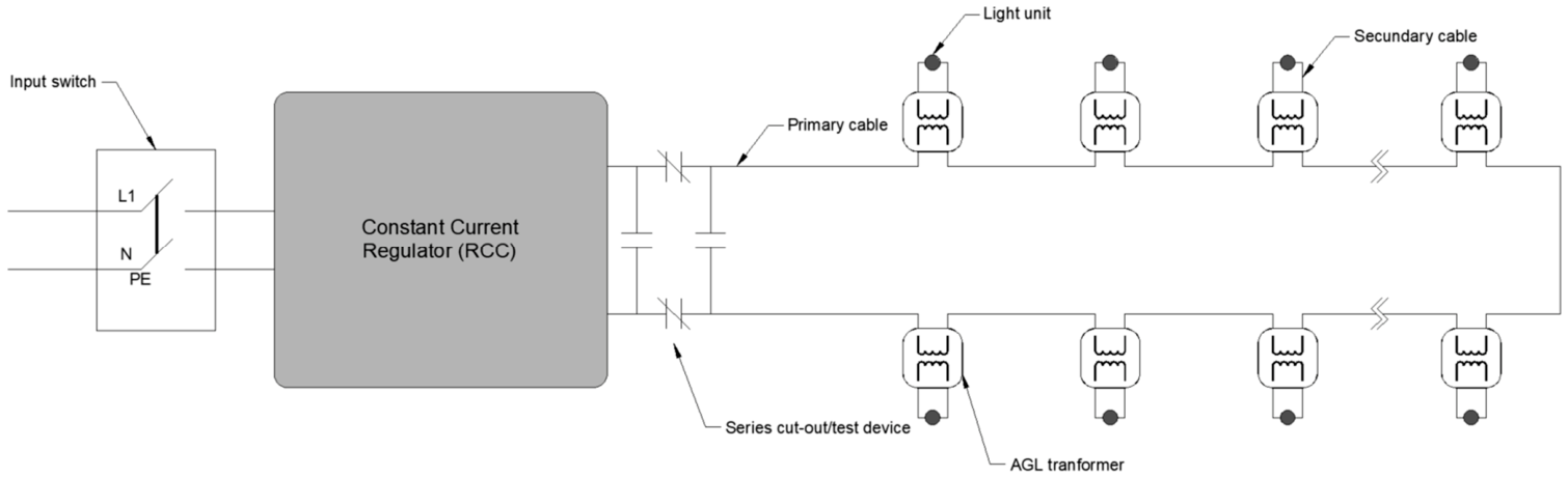
The traditional AGLPS is based on series-connected circuits supplied by Constant Current Regulators (CCR); see
Figure 1. This configuration represents the standard solution prescribed by current regulations and widely deployed in operational aerodromes [
2,
4,
7]. In this architecture, a constant current—which can reach a maximum of 6.6 A— is injected into a closed-loop circuit that feeds all luminaires sequentially along the airfield [
2,
5]. Each luminaire is connected to the series circuit through an individual isolation transformer, which ensures electrical decoupling and allows the system to continue operating even in the event of a lamp failure [
2,
6]. The luminous intensity of all luminaires is controlled simultaneously by adjusting the output current of the CCR, resulting in a uniform brightness level across the entire circuit [
2,
6]. This approach provides high reliability and fault tolerance, which explains its widespread adoption in airport infrastructures.
However, this architecture also entails several inherent limitations. The system operates at high voltages —often in the order of several kilovolts— due to the cumulative voltage drops along the series circuit [
2,
5]. This results in increased insulation requirements and raises safety concerns during installation and maintenance activities. The combination of high operating voltages and continuous current flow introduces a potential risk of electrical arcing, particularly in the presence of insulation degradation, connector failures, or during maintenance operations. This phenomenon may lead to equipment damage, operational disruptions, and increased safety hazards for maintenance personnel [
6].
Furthermore, the series configuration inherently limits system flexibility, as all luminaires are controlled simultaneously through the CCR, preventing individual control and monitoring of each lighting unit. This lack of granularity restricts the implementation of advanced functionalities such as selective dimming, fault isolation, or predictive maintenance. In addition, the dependence on series circuits and isolation transformers increases the complexity of the electrical infrastructure and introduces additional points of failure, leading to higher maintenance requirements and operational constraints [
2].
In recent years, the transition towards LED-based lighting technologies has significantly transformed AGLPS, driven by the need to improve energy efficiency, reduce operational costs, and enhance system reliability. LED luminaires provide clear advantages over traditional incandescent technologies, including higher luminous efficiency, longer service life, and improved photometric stability [
8,
9]. In the context of AGLPS, these benefits translate into reduced energy consumption and maintenance requirements, as well as improved operational safety and sustainability performance [
10]. In addition, LED technology enables advanced functionalities such as dynamic intensity control and digital integration, supporting the evolution towards more intelligent and adaptable lighting systems.
Together with the progressive adoption of LED technology, research efforts have focused on the integration of communication capabilities within AGLPS, particularly through Power Line Communication (PLC). This approach enables data transmission over existing electrical infrastructure, avoiding the need for additional communication networks. Early studies demonstrated the feasibility of PLC-based automation systems for AGLPS control [
11], while subsequent research introduced detailed modelling of AGLPS circuits as communication channels [
12]. These studies highlight significant challenges, including signal attenuation and reflections caused by isolation transformers, as well as the low-pass characteristics of the AGLPS power-line channel [
12,
13,
14].
Other investigations confirm that isolation transformers are the primary source of attenuation in PLC links, whereas cable losses play a secondary role. Additionally, impulsive noise generated by constant current regulators has been identified as a critical factor affecting communication reliability, requiring robust transmission techniques and noise mitigation strategies [
12,
15]. More recent work has extended these concepts by integrating PLC with IoT-based architectures, enabling real-time monitoring and control of individual luminaires through distributed systems and web-based interfaces [
16,
17]. Similarly, alternative network architectures have been proposed to improve system flexibility, scalability, and operational efficiency [
7].
Despite these technological innovations, most existing solutions continue to rely on the traditional series-based electrical architecture, maintaining its inherent limitations in terms of high-voltage operation, limited scalability, and limited flexibility for individual luminaire control. This limitation has been identified in several studies on the evolution of AGLPS and their integration with modern digital technologies [
6,
18]. Consequently, there is a clear gap in the literature regarding the development of alternative electrical architectures that fully exploit the capabilities of LED technology and advanced communication systems.
In this context, parallel power distribution architectures for AGLPS have emerged as a promising research direction. The adoption of LED luminaires, incorporating power electronic converters, enables operation under a wider input voltage range compared to conventional systems. This capability allows for the use of low-voltage parallel distribution networks while maintaining stable luminous output.
Such architectures present several potential advantages, including reduced operating voltages, simplified electrical infrastructure, improved maintainability, and the possibility of individual control and monitoring of each luminaire. In addition, the integration of communication technologies over the power network supports the development of more flexible and digitalised AGL systems.
The implementation of parallel architectures in AGLPS requires careful assessment of aspects such as voltage drop management, brightness uniformity, and communication performance over shared electrical infrastructure.
Similar approaches have been successfully explored in related fields such as microgrids and distributed electrical systems, demonstrating improvements in efficiency, modularity, and fault tolerance [
19,
20,
21]. However, their application to AGLPS introduces new technical challenges, particularly related to voltage drop management, brightness uniformity, electromagnetic compatibility, and communication reliability over shared power lines.
The main goal of this work is to analyse the technical feasibility of implementing parallel electrical circuits in AGLPS using LED luminaires and PLC for control and monitoring purposes. A comparative analysis with the conventional series architecture is conducted on the basis of theoretical modelling and system-level evaluation.
This paper is organised as follows. In
Section 2, the methodology and system modelling approach are described, whereas the results and comparative analysis are included in
Section 3. Finally, the main conclusions are summarized in
Section 5.
2. Materials and Methods
As said in the previous section, an alternative to the current design of AGLPS is proposed and analysed in the present paper. The methodology focuses on: (1) the formulation of a theoretical model describing the electrical power distribution, and the associated control and supervision functions, and (2) its comparison with the conventional series-fed AGLPS architecture currently implemented in airports.
Bearing in mind this conventional design, an alternative AGLPS architecture can be suggested, relying on the parallel feeding of LED luminaires under low-voltage conditions. In this new architecture, each lighting unit is equipped with an individual power conversion stage, allowing the electrical behaviour of each luminaire to be decoupled from the rest of the system. This change constitutes the core of the proposed theoretical model and enables the analysis of the power distribution under low-voltage conditions.
2.1. Definition of the Proposed AGLPS
The aforementioned limitations of the present design of AGLPS have led us to suggest an alternative architecture, particularly in the context of LED-based lighting systems and digital control technologies.
The proposed AGL system is based on a low-voltage (
,
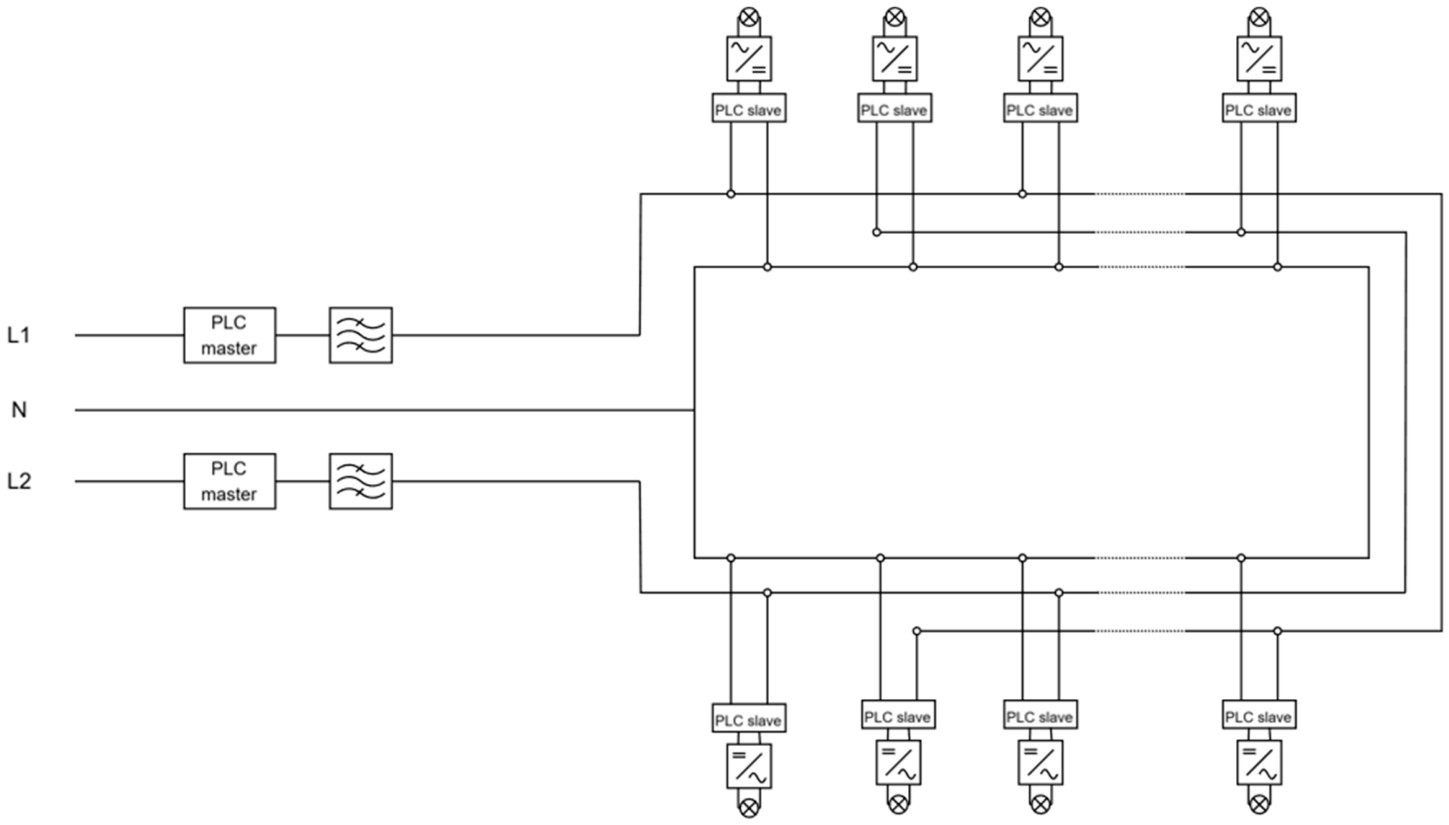
) distribution network feeding LED luminaires connected in parallel along the airfield. Each luminaire integrates an AC/DC rectifier and a DC/DC converter, enabling regulated operation of the LED module.
Figure 2 schematically illustrates the proposed AGLPS architecture based on a low-voltage parallel distribution network. The system comprises an AC power supply network that distributes electrical energy in parallel to a set of luminaires deployed along the airfield. Each luminaire is electrically connected in parallel to the distribution network and incorporates an embedded power supply unit, as well as a slave communication module. The power supply unit consists of an AC/DC rectifier followed by a DC/DC converter, which adapts and regulates the electrical output to the requirements of the lighting device. This configuration ensures stable operation of the luminaire, maintaining consistent luminous output despite voltage variations along the feeder and protecting the system against supply disturbances.
Additionally, the system includes a central communication unit acting as master, connected to the same power distribution network. Communication between the master unit and the slave modules integrated in each luminaire is established through PLC, enabling bidirectional data exchange over the electrical infrastructure. As a result, the same physical medium is used simultaneously for power supply and data transmission. This allows for the implementation of control and monitoring functionalities—such as brightness regulation and status supervision—without requiring additional communication wiring, thereby simplifying the system architecture and enhancing its scalability.
This design introduces a key difference with respect to conventional series-fed systems. In traditional architecture, the luminous output is directly dependent on the current imposed by the CCR, and therefore strongly coupled to the electrical characteristics of the circuit [
2,
6]. In contrast, in the proposed system, the use of power electronic converters allows each luminaire to operate within a wide input voltage range, maintaining a stable output despite variations in the supply voltage.
Therefore, regulation of luminous intensity is no longer determined by the electrical supply conditions but must be explicitly controlled. This requires the implementation of a communication system capable of transmitting control commands to each luminaire. In the proposed architecture, this functionality is achieved through Power Line Communication (PLC), which enables the transmission of brightness setpoints and operational commands over the same electrical infrastructure used for power supply [
13].
2.2. Power Supply System Design
In parallel low-voltage distribution systems, the main design constraint is ensuring that the voltage drop along the feeder does not exceed the maximum admissible value required for correct operation of the most distant luminaires. Unlike conventional power distribution systems, where voltage drop limits are typically restricted to low values (generally in the range of 1–7% for medium-voltage distribution lines, around 3% for lighting circuits, and between 0.5% and 1% for low-voltage feeders supplying sensitive loads [
22]), higher admissible voltage drops can be considered for the proposed system due to the operating range of the power converters. The presence of individual power supplies in each luminaire allows for operation under a wide voltage range. This capability mitigates the impact of voltage drops and enables a more flexible design of the electrical network without compromising brightness uniformity [
23,
24].
2.2.1. Verification of Minimum Conductor Cross-Section
To ensure that the voltage at the end of the feeder remains within acceptable limits, the minimum conductor cross-section must be determined based on the maximum admissible voltage drop. For single-phase low-voltage systems supplying loads with power factor correction, the conductor sizing can be estimated using the classical voltage drop formulation [
23,
25]:
where
is the minimum conductor cross-section,
is the electrical resistivity of the conductor,
is the total circuit length (round trip),
is the total current,
is the power factor,
is the nominal voltage, and
is the maximum admissible voltage drop. This expression is derived from the resistive voltage drop in electrical conductors:
This methodology is widely used in the design of low-voltage electrical installations and provides a practical criterion for conductor sizing in distributed systems [
23,
25].
In the context of the proposed architecture, a key aspect is that the admissible voltage drop can be significantly higher than in conventional systems. This is due to the wide operating voltage range of the AC/DC converters integrated in each luminaire. As a result, the electrical design constraints are relaxed, allowing for the use of standard conductor sections even for long feeder lengths typical of airfield applications.
2.2.2. Case Study Design
To evaluate the technical and economic feasibility of the proposed parallel AGLPS architecture, a representative case study is defined based on a runway edge lighting system installed along a runway of approximately 2000 m in length. This configuration is representative of medium-sized airport infrastructures and is commonly adopted in practical AGL designs [
2,
4].
Runway edge lighting systems consist of luminaires distributed along both sides of the runway, typically spaced at regular intervals in accordance with international standards. For a runway of this length, a total of 66 luminaires is considered, corresponding to a standard deployment of runway edge lights.
In line with recommended design practices for operational reliability and redundancy, the lighting system is divided into two independent electrical circuits, each supplying 33 luminaires. This configuration ensures that, in the event of a failure affecting one circuit, the runway is not left completely without visual guidance, thereby maintaining a minimum level of operational safety [
2].
Each circuit is therefore analysed independently and is considered as a representative feeder of the overall system. The total cable length, including the round-trip distance, is assumed to be = 4800 m, accounting for the physical layout of the installation and the routing of the electrical infrastructure.
The luminaires considered in this study are based on LED technology and incorporate integrated power electronic converters. The apparent power per luminaire is taken as
= 9.9 VA, corresponding to typical low-power LED runway edge lighting fixtures [
26]. The nominal supply voltage is
= 230 V, consistent with low-voltage distribution systems, and the power factor is assumed to be cos
= 0.95, reflecting the behaviour of modern electronic drivers with power factor correction.
The conductor material is assumed to be copper, with a resistivity of
= 1/54 Ω·mm
2/m, which is standard in low-voltage installations [
23].
A key aspect of this analysis is the definition of the maximum admissible voltage drop. In conventional low-voltage systems, voltage drop limits are typically restricted to values below 5% [
22]. However, unlike conventional electrical installations, the proposed architecture incorporates distributed AC/DC power converters integrated within each luminaire. As a result, the luminous output is not directly dependent on the feeder voltage itself, but on the operating range of embedded power electronics.
It should be noted that current aeronautical lighting standards, including ICAO [
1,
2], and IEC 61820-3-2 [
5], do not establish specific voltage-drop limits for low-voltage parallel AGLPS architectures. Existing regulatory frameworks are primarily based on conventional series-fed systems supplied by Constant Current Regulators (CCR). Consequently, the admissible voltage-drop criterion adopted in this work should not be interpreted as a regulatory requirement, but rather as a preliminary engineering design assumption derived from the operating voltage ranges of commercially available AC/DC converters.
To avoid relying on a single commercial product, several representative industrial AC/DC power supplies were reviewed. The XP Power ECE60 series [
27] and the Traco Power TMP/TMPM series [
28] specify universal input voltage ranges of 85–264 VAC, whereas the Cincon CFM61S series [
29] specifies an input range of 90–264 VAC. Assuming a nominal supply voltage of 230 VAC, these ranges would theoretically permit voltage drops of approximately 63.0% and 60.9%, respectively.
Based on these values, and in order to maintain a conservative design margin accounting for thermal effects, cable tolerances, ageing phenomena, and operational uncertainties, a maximum admissible voltage drop of ΔV% = 55% was adopted for the present study.
Nonetheless, this assumption should be regarded as a preliminary design criterion. The actual admissible voltage range of a certified AGL luminaire would ultimately depend on the complete luminaire design, including its embedded power electronics, thermal behavior, electromagnetic compatibility performance, and compliance with the applicable certification framework. Consequently, the absence of explicit regulatory criteria for voltage-drop limits in parallel low-voltage AGLPS architectures is identified as a limitation of the present work and as a subject requiring further experimental validation.
In addition to the electrical analysis, the case study includes a comparative economic assessment between the conventional series-fed AGLPS architecture and the proposed parallel system. The comparison focuses on the electrical power supply infrastructure, considering components such as cables, power supply equipment, and associated installation requirements.
This integrated approach enables the evaluation of both the technical feasibility and the potential economic benefits of the proposed architecture under realistic airfield operating conditions.
2.3. Control and Monitoring System
The proposed system integrates control and monitoring functionalities through Power Line Communication (PLC), enabling data transmission over the same conductors used for power supply. PLC is a well-established technology in industrial and smart grid applications, allowing for communication without additional wiring infrastructure [
13,
14]. PLC operates by superimposing high-frequency signals—typically from tens of kHz to several MHz—onto the low-voltage network. A coupling device injects the carrier signal into the line, while PLC modems located at the control unit and at each luminaire handle modulation and demodulation using techniques such as Orthogonal Frequency Division Multiplexing (OFDM) [
13].
In the proposed architecture/design, the communication system is based on G3-PLC, a narrowband PLC standard specifically designed for robust communication over electrical distribution networks. G3-PLC operates in frequency bands below 500 kHz and employs OFDM modulation combined with forward error correction and adaptive tone mapping, allowing for reliable data transmission in the presence of noise, attenuation, and channel variability [
30,
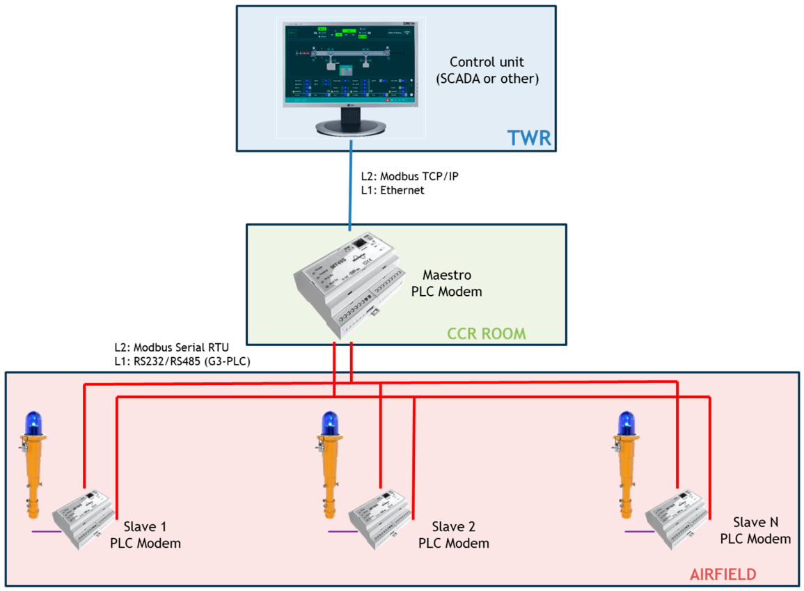
31]. The conceptual network architecture of the proposed PLC-based control and monitoring system can be seen in
Figure 3.
The system follows a hierarchical and distributed structure, with its origin at the Air Traffic Control Tower (TWR). From this location, operators can adjust the brightness levels of the airfield lighting system through a control interface, depending on operational conditions such as visibility, weather conditions, type of operation, or time of service.
Control commands generated at the TWR are transmitted through an Ethernet network using the Modbus TCP/IP protocol to a PLC master modem, which acts as a gateway between the high-level control network and the low-voltage electrical infrastructure. The master modem processes the received data frames and converts them into Modbus RTU messages transmitted over a narrowband PLC network (e.g., G3-PLC) [
28].
These signals are injected into the power distribution network and received by PLC slave modems integrated into each luminaire. Each luminaire executes the received command—such as brightness regulation—and periodically transmits status information back to the control system. This information may include electrical parameters such as voltage, current, and temperature, enabling real-time supervision and predictive maintenance strategies [
17].
The NB-PLC network adopts a mesh topology, providing communication redundancy and robustness against disturbances or local failures [
28]. This architecture enables a scalable, efficient, and non-intrusive control system, leveraging the existing electrical infrastructure while minimising deployment costs.
At the application level, communication is implemented using the Modbus protocol, a widely adopted industrial standard for reliable data exchange in master–slave architectures [
32]. Each luminaire is assigned a unique address, allowing for selective control and monitoring from the central unit.
Through this communication framework, the system supports the transmission of control commands—such as brightness regulation (SetIntensity)—as well as monitoring signals including luminaire status, electrical parameters, and fault diagnostics. This enables centralized supervision and individual control of each lighting unit, which is not achievable in conventional series-fed AGL systems.
2.3.1. Command Structure and Signal Typology
The communication system supports bidirectional data exchange between the central control system and each luminaire. Two main types of signals are defined:
This approach enables centralized supervision and individual control of each lighting unit, in line with recent developments in smart lighting systems and IoT-based infrastructures [
16,
17].
2.3.2. Modbus-Based Communication Model
Communication in the proposed system is implemented using the Modbus protocol, a widely adopted industrial standard for reliable data exchange in distributed control systems [
32]. Modbus enables deterministic communication through a master–slave architecture, in which a central controller (master) exchanges information with multiple field devices (slaves), such as the luminaires in the AGL system.
Two main variants of the Modbus protocol are commonly used: Modbus RTU and Modbus TCP/IP. Modbus RTU is a serial communication protocol that transmits data in binary format over physical media such as RS-485 or power line communication channels. In contrast, Modbus TCP/IP operates over Ethernet networks, encapsulating Modbus frames within TCP/IP packets and using a client–server communication model [
32,
33,
34].
In terms of addressing capacity, Modbus RTU supports up to 247 slave devices per master due to its 8-bit addressing scheme. This limitation is compatible with AGL systems, where the number of luminaires per circuit is typically well below this threshold [
33]. Modbus TCP/IP, on the other hand, allows a significantly larger number of devices through IP-based addressing, although it requires additional communication infrastructure such as Ethernet networks and associated hardware [
34].
In the context of the proposed AGLPS architecture, Modbus RTU is considered the most suitable option due to its compatibility with G3-PLC, its robustness in electrically harsh environments, and its lower implementation complexity. The use of Modbus RTU over PLC enables reliable communication over the existing power distribution network without requiring additional communication cabling.
Each luminaire is assigned a unique address within the Modbus network, allowing for selective control and monitoring. Through this framework, the system supports the transmission of control commands—such as brightness regulation (SetIntensity)—as well as monitoring signals including luminaire status, electrical parameters, and fault diagnostics (QueryStatus).
The transmission time,
, of a communication frame can be expressed as:
where
is the total number of bits in the communication frame, and
is the communication bit rate. The total response time is therefore:
where
represents the processing time at the receiving device, including frame decoding, command execution, and response generation. This formulation provides the basis for evaluating system response times and will be used in
Section 3 to assess compliance with operational requirements.
2.4. Methodological Approach
The methodology combines electrical design based on voltage drop criteria with communication modelling based on PLC and Modbus protocols. This integrated approach enables the evaluation of the proposed architecture from both electrical and operational perspectives. A conceptual comparison between the traditional series-fed architecture and the proposed parallel system is carried out using criteria such as electrical performance, safety, maintainability, and control capabilities. This comparison provides the basis for the results presented in
Section 3.
3. Results
3.1. Electrical Feasibility of the Parallel AGL System
Based on the case study defined in
Section 2.2.2, the electrical feasibility of the proposed parallel AGLPS architecture is evaluated for a representative feeder supplying 33 luminaires. Under these conditions, the total current of the feeder is calculated as:
then, using the conductor sizing formulation introduced in
Section 2.2.1, the minimum required conductor cross-section is obtained as:
Substituting the parameters defined in
Section 2.2.2, it is possible to derive the following expression:
Since this value does not correspond to a standardised conductor size, the immediately higher commercial section is selected . This result demonstrates that, even for long feeder lengths typical of runway lighting systems, the required conductor section remains within standard low-voltage installation ranges. More importantly, the analysis confirms that the voltage drop does not compromise the operation of the luminaires. Thanks to the embedded power supplies, each lighting unit maintains stable luminous output within the allowable input voltage range, effectively decoupling electrical distribution constraints from photometric performance. This validates the feasibility of the proposed parallel architecture in realistic airfield conditions and highlights its potential to simplify electrical design while maintaining operational reliability.
3.2. Impact of Voltage Drop on System Performance
In conventional series-fed AGL systems, the electrical behavior of the circuit is governed by the constant current imposed by the CCR. Under this configuration, all luminaires are electrically coupled, and their luminous output is directly determined by the circuit current. As a result, brightness uniformity is inherently guaranteed, independently of cable length or voltage distribution along the feeder [
2,
5].
However, this approach requires the system to operate at high voltages to compensate for cumulative voltage drops, while offering limited flexibility in terms of individual control and monitoring [
2,
6].
In contrast, in the proposed parallel architecture, the electrical behavior of the system is fundamentally different. The supply voltage varies along the feeder due to resistive voltage drops, and therefore each luminaire is subject to a different input voltage depending on its position within the network [
23,
25].
Despite this variation, the use of embedded AC/DC converters in each luminaire ensures that the luminous output remains stable, as long as the input voltage remains within the specified operating range of the power supply. This behaviour is consistent with the operation of regulated electronic loads and LED drivers, which are designed to maintain constant output under varying input conditions [
10].
Consequently, voltage drop—while still a relevant design parameter—no longer directly affects brightness uniformity but instead defines the operational limits of the feeder. This represents a fundamental shift compared to conventional AGL systems, where electrical and photometric behaviours are tightly coupled.
The results obtained in
Section 3.1 confirm that, even under significant voltage drops, the luminaires operate within their acceptable input voltage range. Therefore, the proposed architecture allows for a relaxation of traditional voltage drop constraints without compromising system performance.
This characteristic provides a significant advantage in terms of system design, enabling longer feeder lengths, reduced conductor requirements, and increased flexibility in the layout of the electrical infrastructure.
3.3. Comparative Electrical System Cost Assessment
In addition to the technical feasibility, a comparative economic assessment between the conventional series-fed AGLPS architecture and the proposed parallel system is carried out based on the case study defined in
Section 2.2.2. Traditional AGL systems rely on series circuits supplied by CCRs, requiring high-voltage equipment, including isolation transformers for each luminaire and specialised cabling designed to withstand elevated voltage levels [
2,
4,
5]. These elements significantly increase both installation complexity and overall system cost. In contrast, the proposed parallel architecture operates at low-voltage and replaces isolation transformers with integrated AC/DC power supplies within each luminaire. This reduces the number of external components and enables the use of standard low-voltage cabling, contributing to a simplification of the electrical infrastructure [
23]. A qualitative comparison of the main technical and cost-related characteristics between both architectures is presented in
Table 1.
As shown in
Table 1, the proposed parallel architecture simplifies the electrical infrastructure and enhances system flexibility, particularly in terms of scalability, maintenance, and fault isolation. These conceptual advantages are further reflected in the quantitative cost analysis presented below. Based on technical specifications and unit prices obtained from manufacturers and recent airport engineering projects (2024–2025), a cost assessment of the power supply system has been performed for both configurations shown in
Table 2. The analysis considers only the main electrical equipment required for the runway edge lighting system.
It should be noted that the present assessment only considers the electrical infrastructure directly associated with the power supply system. Additional elements such as PLC devices, supervisory systems, gateway equipment, installation-specific civil works, and long-term operational costs were not included in the analysis and should be addressed in future studies.
The results show that the proposed parallel architecture leads to a reduction of approximately 31,941 € in the total cost of the power supply system, corresponding to a decrease of around 33% compared to the conventional series configuration. This cost reduction is mainly attributed to the elimination of isolation transformers, the use of low-voltage cabling with lower insulation requirements, and the simplification of the electrical installation. Although the parallel system requires shielded cables to support PLC, the overall cost remains significantly lower than that of the series-based system. From an operational perspective, additional economic benefits can be expected due to reduced maintenance complexity, improved accessibility, and lower safety constraints associated with low-voltage operation [
6].
It should be noted that the present comparison is limited to the electrical power distribution infrastructure associated with both AGLPS architectures. Therefore, communication hardware, supervisory systems, civil works differences, operational expenditure (OPEX), and lifecycle costs are outside the scope of this assessment.
Overall, the proposed architecture demonstrates a clear economic advantage over conventional AGL systems, particularly in installations with long feeder lengths and a high number of luminaires, such as runway lighting systems.
3.4. Communication Performance Using PLC and Modbus
In conventional AGL systems based on series circuits and constant current regulators (CCR), the regulation of luminous intensity is achieved by modifying the output current of the CCR. This approach does not require a distributed communication system, as all luminaires operate simultaneously and uniformly under the same electrical conditions [
2,
5]. In contrast, the proposed parallel architecture requires the implementation of a communication system to enable individual control and monitoring of each luminaire. This introduces additional functional requirements, including reliable data transmission, addressing capability, low latency, and robustness against disturbances in the electrical network.
The use of G3-PLC as a communication technology provides a suitable solution to these requirements. G3-PLC is designed for operation over low-voltage distribution networks and incorporates mechanisms such as OFDM modulation, forward error correction, and adaptive tone mapping, which enhance communication reliability in the presence of noise, attenuation, and impedance discontinuities [
13,
28]. These characteristics are particularly relevant in AGL systems, where long cable lengths and distributed loads may affect signal propagation.
At the application level, communication is implemented using the Modbus RTU protocol over PLC. The performance of the system can be evaluated through representative control and monitoring commands. The
SetIntensity command is used to regulate the brightness level of all luminaires simultaneously. This functionality is implemented using the Modbus function code 0 × 06 (Write Single Register) and is transmitted in broadcast mode (address 0 × 00), ensuring that all luminaires receive the command without requiring individual responses [
35]. In this approach, each luminaire is associated with a dedicated register representing its luminous intensity level. The brightness levels are encoded as integer values, as shown in
Table 3.
The Modbus RTU frame structure for the
SetIntensity command is summarised in
Table 4. In Modbus RTU, registers are addressed starting from zero; therefore, register 0x0000 can be defined as the “luminaire intensity register” [
35]. As the message is transmitted in broadcast mode, all luminaires accept the command but do not generate a response. A complete frame example for a 100% brightness command is:
. The total frame length is 8 bytes (64 bits). Assuming a communication rate of 19.2 kbps and a transmission format of 11 bits per byte (including start, data, parity, and stop bits), the transmission time per byte can be calculated using (3) as:
Thus, the total transmission time for the
SetIntensity command is:
This result demonstrates that the brightness command can be transmitted to all luminaires in less than 5 ms.
For monitoring purposes, the QueryStatus command is used to retrieve electrical parameters from a specific luminaire. In the proposed system, three consecutive registers are accessed:
Register 0 × 0001: input voltage (mV)
Register 0 × 0002: measured current (mA)
Register 0 × 0003: LED module temperature (tenths of °C)
This operation is implemented using the Modbus function code 0 × 03 (Read Holding Registers) in unicast mode, specifying the address of the target luminaire [
35]. The request Protocol Data Unit (PDU) includes the starting register address and the number of registers to be read. In Modbus addressing, registers are indexed from zero; therefore, registers numbered from 1 to 16 are addressed as 0–15 [
35]. In the response message, each register value is encoded using two bytes, with the most significant byte transmitted first, followed by the least significant byte. The Modbus RTU request and response frames for the
QueryStatus command are summarized in
Table 5 and
Table 6, respectively.
The aforementioned procedure and data illustrate the bidirectional nature of monitoring operations, where both request and response messages must be transmitted, resulting in a higher communication overhead compared to broadcast control commands. In this case, the complete communication exchange consists of 19 bytes (8 bytes for the request and 11 bytes for the response). Assuming a communication rate of 19.2 kbps and a transmission format of 11 bits per byte, the transmission time per byte can be calculated using (3) as:
The transmission time for the request and response frames is therefore:
The total transmission time is:
In addition, the processing time at the luminaire must be considered. Therefore, the overall response time can be estimated using Equation (4) as:
resulting in a total response time slightly above 10 ms, depending on the processing capabilities of the device. Considering typical processing times in embedded communication devices, which are generally in the order of a few milliseconds, the overall response time can be reasonably expected to remain below 20 ms.
Considering the case study defined in
Section 2.2.2, each runway edge lighting circuit comprises 33 luminaires. Therefore, assuming sequential polling of all luminaires using the
QueryStatus command, the total communication cycle time can be estimated as:
Assuming ideal communication conditions and neglecting additional retransmissions or network delays, the total monitoring cycle would be in the order of:
This value remains below the operational response time requirements typically associated with AGL systems, including the one-second response requirement for CAT II/III operations defined by ICAO and EASA regulations [
1,
3].
These results demonstrate that monitoring operations can be performed within time scales of a few milliseconds, which is well within the operational requirements of AGL systems [
1,
3]. Consequently, the proposed PLC-based communication system meets the performance requirements for real-time control and monitoring of AGL systems, while enabling functionalities that are not achievable in conventional architectures, such as individual luminaire control, real-time diagnostics, and predictive maintenance.
Although the introduction of a communication layer increases system complexity compared to traditional CCR-based systems, this is compensated by the enhanced flexibility, scalability, and operational capabilities provided by the proposed architecture.
Nevertheless, the previous timing analysis represents an ideal upper-bound estimation based on nominal communication rates and simplified transmission assumptions. In real operational environments, the performance of G3-PLC networks may be affected by additional factors such as inter-symbol interference caused by long cable lengths, multipath reflections, impulsive noise generated by power electronic converters, impedance discontinuities, and medium-access delays associated with the MAC layer [
12,
13,
15].
Consequently, the effective communication throughput may be lower than the theoretical values considered in this work. However, previous studies on narrowband PLC systems in electrical distribution networks and AGL environments have demonstrated the feasibility of reliable communication under comparable operating conditions [
11,
12].
4. Discussion
The results obtained in this study demonstrate the technical feasibility of implementing parallel low-voltage architecture for Airfield Ground Lighting Power Systems (AGLPS), integrating distributed power electronics and communication capabilities through Power Line Communication (PLC). From both electrical and operational perspectives, the proposed approach addresses several of the limitations inherent to conventional series-fed systems.
From an electrical standpoint, the analysis shows that the use of local AC/DC and DC/DC conversion stages in each luminaire effectively decouples the luminous output from the supply voltage variations along the feeder. This represents a fundamental shift from traditional constant-current-based operation, where the luminous intensity is intrinsically linked to the electrical behavior of the entire circuit [
2,
6]. As demonstrated in
Section 3.1, the admissible voltage drop can be significantly increased without compromising system performance, which relaxes conductor sizing constraints and enables the use of standard low-voltage infrastructure [
23,
25]. This finding is consistent with broader trends observed in distributed electrical systems and microgrid architectures, where local power conditioning allows for more flexible network design [
19,
20,
21].
From a communication perspective, the integration of PLC and Modbus protocols enables functionalities that are not achievable in conventional AGL systems. The results presented in
Section 3.4 indicate that both control and monitoring operations can be executed within time scales of a few milliseconds, well below the operational requirements defined by international regulations [
1,
3]. This confirms that the transition from current-driven to communication-based control does not compromise system responsiveness. Moreover, the use of broadcast and unicast communication mechanisms allows for efficient system-wide control while enabling detailed supervision at the luminaire level.
These findings are aligned with previous studies that have explored the application of PLC in AGL systems [
11,
12], where the feasibility of data transmission over power lines was demonstrated despite the presence of attenuation and noise. However, unlike most existing approaches, which are constrained by the traditional series architecture, the proposed system leverages a parallel topology that inherently facilitates communication by eliminating the dominant attenuation effects associated with isolation transformers. This represents a key contribution to the present work.
From an operational and economic perspective, the results also indicate that the proposed architecture can lead to a reduction in system complexity, installation costs, and maintenance requirements. As shown in
Section 3.3, the elimination of isolation transformers and the use of low-voltage cabling contribute to a more efficient and scalable system. These advantages are particularly relevant in the context of ongoing efforts to modernize airport infrastructure and improve sustainability performance [
10,
13].
Unlike conventional series-fed AGL systems, where electrical continuity is inherently maintained through the use of isolation transformers, the proposed parallel architecture requires an alternative protection philosophy adapted to low-voltage distribution systems. In the proposed configuration, individual luminaires operate independently and are connected in parallel to the feeder. Consequently, local luminaire failures would not directly interrupt the operation of the remaining lighting units. However, feeder-level faults, such as short circuits or cable failures, could potentially affect multiple downstream luminaires depending on the protection topology adopted.
To mitigate these risks, the proposed architecture would require the implementation of coordinated low-voltage protection devices, including feeder circuit breakers, branch protection elements, and earth-fault protection mechanisms. In practice, the distribution network could be divided into electrically segmented sections in order to limit the impact of feeder faults and improve fault isolation capability. Nevertheless, the detailed design of the protection coordination scheme, including short-circuit protection, selectivity criteria, earth-fault detection, and compliance with integrity requirements applicable to CAT II/III operations, remains outside the scope of the present work and should be addressed in future studies.
Recent studies on multiport power-electronic systems and solid-state transformer architectures have shown that dynamic interactions between distributed converters, synchronization loops, and communication or control layers may become a significant source of instability under disturbed operating conditions and weak-grid scenarios [
37,
38]. In this context, future implementations of the proposed AGL architecture should also consider the potential impact of converter interaction dynamics, communication delays, and coordinated protection strategies during transient and fault conditions.
Nevertheless, the implementation of the proposed architecture introduces new challenges that must be carefully considered. In particular, the increased reliance on communication systems raises issues related to electromagnetic compatibility, cybersecurity, and system resilience under fault conditions. While technologies such as G3-PLC provide robust communication mechanisms, their performance in large-scale operational environments with high electromagnetic interference should be further validated. Additionally, the transition from a centralized CCR-based control paradigm to a distributed communication-based system requires new approaches to system certification and regulatory compliance.
Future research should therefore focus on the experimental validation of the proposed architecture under real operating conditions, including large-scale field trials. Particular attention will be given to the detailed characterization of G3-PLC signal propagation, including attenuation, multipath effects, impulsive noise, electromagnetic interference, and their impact on communication reliability within airport electrical infrastructures. Further work is also required to analyze electromagnetic compatibility in complex airport environments, as well as to assess the impact of communication failures on system safety and redundancy. In addition, future studies should address lifecycle cost assessment, long-term reliability analysis, maintenance optimization strategies, and operational expenditure associated with the proposed architecture. The integration of advanced control strategies and predictive maintenance algorithms could further enhance the performance and reliability of the system.
Overall, the results presented in this study support the hypothesis that parallel low-voltage AGLPS architectures, enabled by LED technology and PLC-based communication, constitute a viable and advantageous alternative to conventional series-fed systems. This approach opens new possibilities for the digitalization and optimization of airfield lighting systems, contributing to the evolution of airport infrastructure towards more flexible, efficient, and intelligent solutions.