1. Introduction
Coal roadways are essential engineering structures for ventilation, transportation, and production continuity in underground coal mines. As mining extends to greater depths, roadway stability is increasingly challenged by high in-situ stress, strong mining disturbance, complex roof structures, and variable geological conditions, making support design a key issue for safe and efficient coal extraction [
1,
2,
3]. In engineering practice, support schemes are still commonly determined through empirical analogy and field-based adjustment. Although this approach is convenient, its applicability is often limited because similar support layouts may produce markedly different control effects under different stress environments and roadway conditions [
4,
5,
6]. Deep-roadway case studies have further shown that long bolts, adjacent-roadway pressure relief, and roof-cutting measures may all improve local stability, but their effectiveness remains strongly case-dependent [
7,
8,
9].
The understanding of bolt–cable support has gradually evolved from classical suspension and composite-beam concepts toward coordinated reinforcement mechanisms emphasizing anchorage effectiveness, pretension transfer, and full-stress control [
1,
10,
11]. Recent studies have shown that support performance in deep and weak roadways is strongly affected by roof lithology, mining disturbance, and the coupling between reinforcement components and surrounding rock [
12,
13,
14]. In parallel, numerical simulation has become a widely used tool for evaluating stress redistribution, plastic-zone evolution, and the mechanical response of supported roadways before field implementation [
5,
15,
16]. However, purely numerical design is often time-consuming and remains sensitive to constitutive assumptions and parameter calibration [
4,
6].
For data-driven support design, artificial intelligence should be understood as a surrogate decision tool rather than as a direct physical sensor. Machine-learning models do not directly “sense” the in-situ stress field; they approximate the relationship between measurable or encoded engineering descriptors and target design variables. In the present problem, burial depth, roadway width and height, roof thickness, lithologic category, density, and friction angle are used as proxies for the stress-bearing environment and the excavation-support interaction. These descriptors cannot reproduce the complete three-dimensional stress path, but they can provide a compact representation of the main conditions controlling support selection when combined with mechanical constraints. Previous studies have shown that machine-learning methods are useful for roof-quality classification, roadway-stability prediction, and nonlinear rock-engineering response estimation because they can identify patterns that are difficult to express using a single empirical formula [
17,
18,
19,
20,
21]. Their relevance to this study lies in the ability to learn preliminary associations between roadway conditions and support parameters, not in replacing the mechanical interpretation of the excavation and support system.
However, support design cannot be treated as a purely statistical regression problem. A predicted bolt length or spacing is acceptable only if it is compatible with classical support principles, including sufficient anchorage length, effective load transfer, reasonable spacing, adequate bolt–cable coordination, and constructability in the roadway section [
1,
2,
10,
11,
14]. Therefore, the role of machine learning in this study is deliberately limited: it provides a preliminary recommendation, while the final values are corrected by theoretical and engineering rules before numerical verification. This distinction is important because it connects the learned variables with the in-situ stress environment through physically interpretable descriptors and then constrains the output according to the mechanics of the excavation-support system.
Recent mining-related machine-learning studies also emphasize that predictive accuracy alone is insufficient when decisions must be made under limited samples, geological uncertainty, and engineering constraints. For example, recent work on mineral-resource categorization has compared RF, XGBoost, neural-network and geostatistical descriptors for classification tasks, while recent reviews of underground-mining uncertainty highlight the need to explicitly consider data limitations and decision robustness in underground operations [
22,
23,
24]. Compared with these studies and with existing ML-based roadway-stability prediction, the specific advance of the present work is that the ML output is not used as a direct black-box design. Instead, it is treated as a preliminary parameter recommendation and is subsequently filtered through engineering specifications, theoretical limits, constructability rules, and FLAC3D verification. Therefore, the contribution is methodological rather than merely algorithmic: it provides a constrained decision route for roof bolt-cable parameter selection under small-sample conditions.
Accordingly, this study tests the hypothesis that a theory-constrained machine-learning workflow can provide a more targeted and interpretable roof-support design than direct empirical continuation alone. The workflow first predicts support parameters from case data, then revises the predicted outputs according to engineering rules and theoretical constraints, and finally evaluates the resulting scheme through FLAC3D simulation. The 11104 return-air roadway of Jingu Mine is selected as the main validation case, while the Sanxia 1008 material roadway of Fucun Mine is used as an external consistency case. The contribution of this study lies not only in generating a data-driven parameter set, but also in establishing an interpretable support-design route in which machine-learning prediction, theoretical correction, and numerical verification are integrated into a unified engineering framework.
2. Materials and Methods
2.1. Overall Workflow
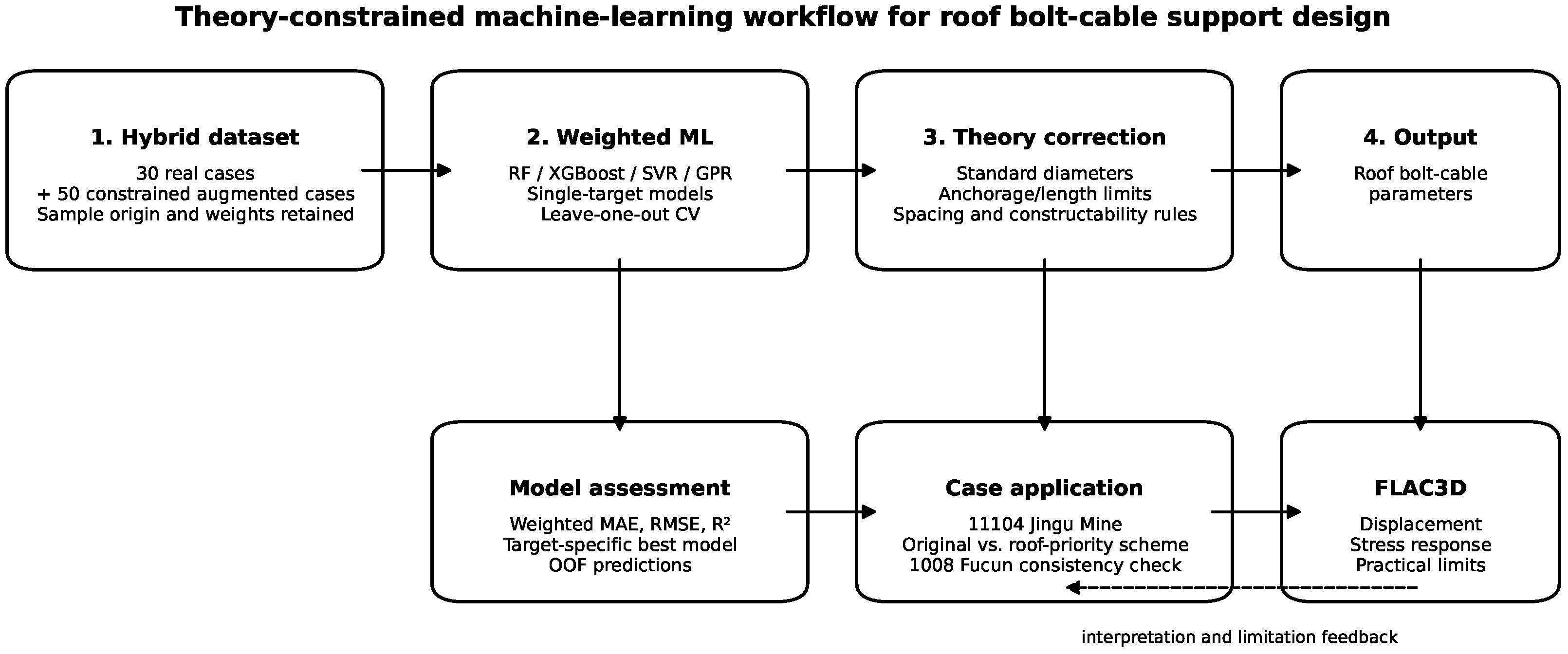
The overall workflow is shown in
Figure 1. The study consists of four stages: (i) construction of a hybrid dataset; (ii) weighted single-target machine learning modeling; (iii) case-specific parameter generation under theoretical and engineering constraints; and (iv) FLAC3D verification of the original and roof-priority optimized schemes for the main case. The workflow was designed to retain interpretability throughout the full process. The workflow figure explicitly shows the input features, output targets, sample-weighting stage, theoretical correction stage, model-validation step, and numerical-verification step.
The machine-learning analysis was implemented in Python 3.10.18 (Anaconda distribution, 64-bit Windows platform) using pandas 2.3.3, NumPy 2.2.5, scikit-learn 1.7.1, XGBoost 3.2.0, and joblib 1.5.3. The numerical verification was carried out using FLAC3D 7.0. All numerical comparisons between the original and optimized schemes used the same model geometry, mesh, boundary conditions, constitutive assumptions, and monitoring paths.
2.2. Hybrid Dataset Construction
A hybrid dataset with 80 samples was established. It includes 30 real engineering cases extracted from operation regulations, support design documents, and published engineering studies, together with 50 constrained augmented samples generated around the real cases. The augmentation was not random oversampling. Only seed cases marked as suitable for modeling were used, and each selected seed case generated two constrained samples. The input perturbations were restricted to nearby-mine or same-roadway engineering ranges. In the generated dataset, the perturbation ranges relative to the seed cases were approximately as follows: burial depth, to m; main roof thickness, to m; main roof competency coefficient, to ; immediate roof thickness, to m; immediate roof competency coefficient, to ; roadway width, to m; and roadway height, to m. The output parameters were not freely perturbed; they were mapped to common engineering specifications or limited increments, including standard bolt/cable diameters, typical anchorage lengths, and commonly adopted spacing-row-spacing intervals. Real cases were assigned higher weights (0.70–1.00 according to completeness and provenance), whereas constrained augmented cases were assigned lower weights (0.55–0.65). Specifically, complete field or design records received the highest weights, partially reconstructed real cases received intermediate weights, and the augmented cases received the lowest weights. This strategy was used to reduce artificial bias from the augmented samples and to prevent them from dominating the training process.
The input and output variables used in the machine learning models are listed in
Table 1. Because roof-support records are more complete and more standardized than rib-support records in the available case library, the machine learning outputs were limited to roof-related parameters. Rib-bolt parameters were therefore retained from the field scheme or supplemented later by engineering rules.
The coded input descriptors were further defined to avoid ambiguity. The roof lithologic assemblage index (
) is an ordinal descriptor derived from the number and contrast of roof layers near the roadway. Low values indicate a relatively simple or massive roof, whereas higher values indicate more strongly layered or structurally complex roof conditions. The fault/mining-disturbance index (
) is a binary descriptor derived from geological records and mining-layout information, where 0 indicates no clear fault or strong mining-disturbance influence and 1 indicates the presence of such influence in the case record. These descriptors are therefore engineering-coded variables rather than direct laboratory measurements. The constrained augmentation and weighting rules are summarized in
Table 2.
The sample weight was assigned before model training according to the reliability class of each record. Complete real engineering cases with documented geometry, lithology, and support parameters were assigned ; real cases with partial reconstruction or minor missing descriptors were assigned –0.85; constrained augmented samples generated from complete real cases were assigned –0.65; and augmented samples generated from less complete base cases were assigned –0.60. These values were used as reliability weights rather than as fitted parameters. They were fixed before cross-validation and were not tuned to improve the final metrics.
2.3. Weighted Single-Target Modeling
Each support target was modeled independently. Four regressors were compared: random forest (RF), XGBoost, support vector regression (SVR), and Gaussian process regression (GPR). The model settings were fixed before the final comparison to avoid excessive tuning on the small dataset. RF used 300 trees with bootstrap aggregation; XGBoost used 200 estimators, a maximum depth of 3, a learning rate of 0.05, a subsampling ratio of 0.90, and a column-sampling ratio of 0.90; SVR used a radial-basis-function kernel with standardized input features; and GPR used a constant kernel multiplied by an RBF kernel plus a white-noise kernel. Leave-one-out cross-validation (LOOCV) was used because the dataset contained only 80 samples. In each fold, one sample was held out for prediction and the model was fitted using the remaining 79 samples. The reported metrics are therefore out-of-fold metrics rather than apparent fitting results calculated on the full training set. To reduce the dominance of constrained augmented samples while preserving the priority of real engineering cases, weighted learning was adopted whenever the estimator supported sample weights. For GPR, sample weights were not used in fitting because of implementation limitations, but all reported metrics were still calculated in weighted form. Model performance was evaluated by weighted mean absolute error (MAE), weighted root mean square error (RMSE), and weighted coefficient of determination (
):
Equations (1)–(3) are the standard weighted forms of MAE, RMSE, and used in regression evaluation when observations have unequal reliability or importance. They are obtained by replacing the unweighted summation in the conventional MAE, RMSE, and residual-sum-of-squares expressions with weighted summations. Here, n is the number of samples, is the fixed reliability weight of the ith sample, is the observed engineering design value, is the out-of-fold prediction obtained in LOOCV, and is the weighted mean of the observations. In this study, was calculated from the sample-reliability class defined above before model training. Higher weights were assigned to real engineering cases because they represent measured or documented field designs, whereas lower weights were assigned to constrained augmented samples because they were generated as engineering supplements rather than independent field observations. In practical terms, reflects confidence in the sample source and completeness; it is not a physical parameter measured in the field and is not adjusted during model fitting.
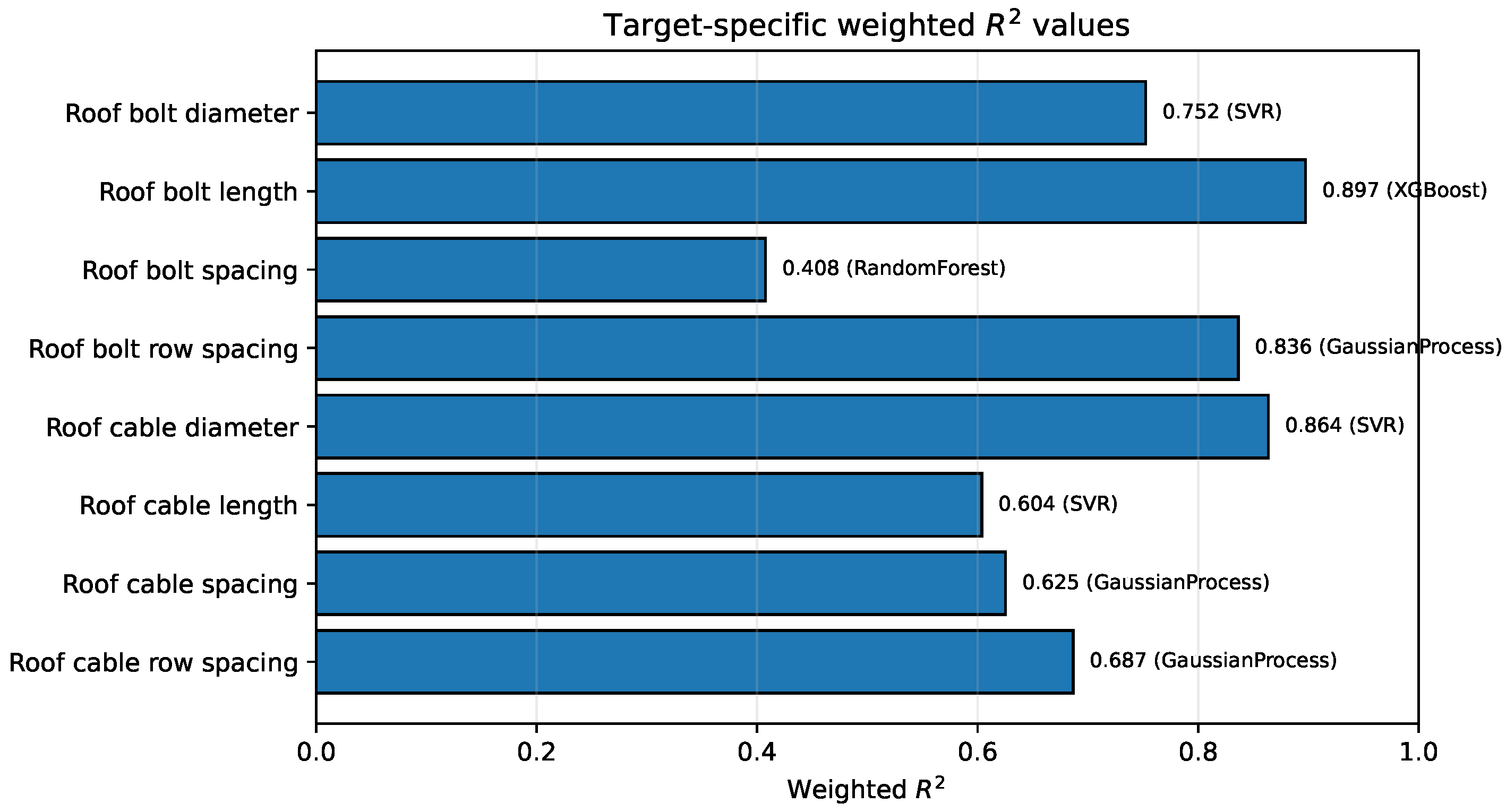
The best model selected for each prediction target is summarized in
Table 3, and the corresponding weighted
values are shown in
Figure 2. Model selection was based on a composite ranking of standardized weighted MAE, standardized weighted RMSE, and weighted
. The results indicate strong heterogeneity across support targets: no single regressor dominates all outputs. XGBoost performed best for roof bolt length, SVR for roof bolt diameter, roof cable diameter, and roof cable length, RF performed best for roof bolt spacing, and GPR performed best for row-spacing and cable-spacing variables. The relatively low weighted
for roof bolt spacing (0.4075) indicates that this target remains more weakly constrained by the current input descriptors and should be interpreted with assistance from engineering spacing rules rather than as a purely data-driven decision.
2.4. Theory-Based Correction and Decision Rules
The machine-learning output was not used directly as the final support scheme. A rule-based correction layer was applied to ensure that the generated parameters were consistent with engineering specifications and constructability. The correction logic can be summarized as follows. First, bolt and cable diameters were rounded to the nearest standard specification, and if a theoretical or specification-based minimum existed, the rounded value could not be smaller than that minimum. Second, roof bolt and cable lengths were controlled by both the ML prediction and theoretical anchorage requirements; the final length was taken as the larger value between the ML estimate and the theoretical minimum, followed by engineering rounding. Third, spacing-related variables were treated more conservatively because several spacing targets showed weaker predictive performance. For these variables, theoretical or empirical spacing rules were given priority, while the ML value was used mainly as an auxiliary reference or fallback. Fourth, rib-support parameters were not predicted by the present ML model because the available case library contained more complete and standardized roof-support records than rib-support records. Rib bolts were therefore retained from the original field scheme for the main case.
This correction layer is the main distinction between the proposed workflow and direct ML regression. It prevents nonstandard outputs such as unrealistic diameters, nonconstructible lengths, or overly dense/sparse spacing from entering the numerical-verification stage. The pseudocode is given below to improve reproducibility:
For each roof-support target:
ML prediction <- target-specific best regressor
If diameter target:
final <- nearest standard diameter not smaller than theory minimum
If length target:
final <- max(ML prediction, theoretical anchorage minimum)
final <- rounded to practical construction precision
If spacing target with modest predictive reliability:
final <- theoretical/empirical spacing rule first
ML prediction used as auxiliary fallback only
Rib parameters:
retain original field scheme or confirm manually
A simple rank-correlation sensitivity check was also conducted to identify which descriptors were most closely associated with individual targets. For roof bolt length, the strongest correlations were obtained for immediate roof thickness (), burial depth (), and roadway height (). For roof bolt diameter, burial depth showed the strongest positive association (). For roof bolt spacing, the largest absolute correlations were lower than those for bolt length, which is consistent with its weaker weighted and the need to treat spacing as an ML-assisted rather than ML-determined parameter.
2.5. Case Selection and Engineering Interpretation
Two engineering cases were selected. The 11104 return-air roadway of Jingu Mine was used as the main verification case because its roadway geometry, roof structure, and original support system were well documented and an available FLAC3D model already existed. The Sanxia 1008 material roadway of Fucun Mine was selected as an external consistency case because it had been used in earlier intelligent support-design research and had a documented field-adjusted roof-support scheme for comparison.
The key geometric and geological information of the two cases is listed in
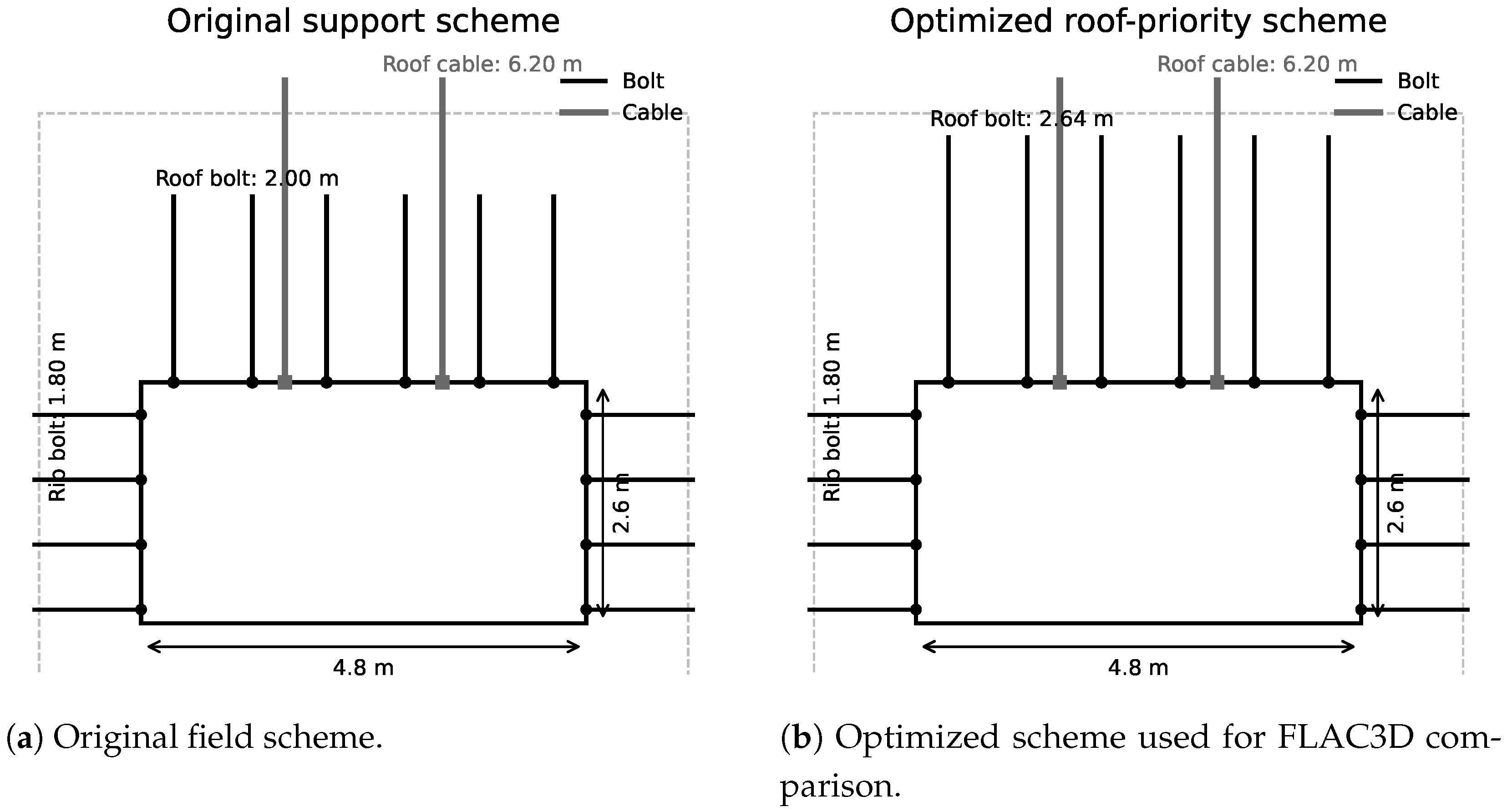
Table 4. For the 11104 return-air roadway, the excavation specification in the operation regulation was 4.8 m × 2.8 m, whereas the net roadway section was 4.8 m × 2.6 m. The numerical simulation in this study strictly adopted the net section, namely 4.8 m × 2.6 m, as the excavation section in the FLAC3D model.
For the Fucun Mine Sanxia 1008 material roadway, the burial depth was not given as a single value in the original case summary used in the previous version. After rechecking the operation regulation, the working face was found to be located at the
m level, while the reported ground elevation ranged from
to
m. Therefore, the burial depth was estimated as approximately 512–516 m and added to
Table 4.
4. FLAC3D Numerical Model
4.1. Geometric Model, Boundary Conditions, and Monitoring Strategy
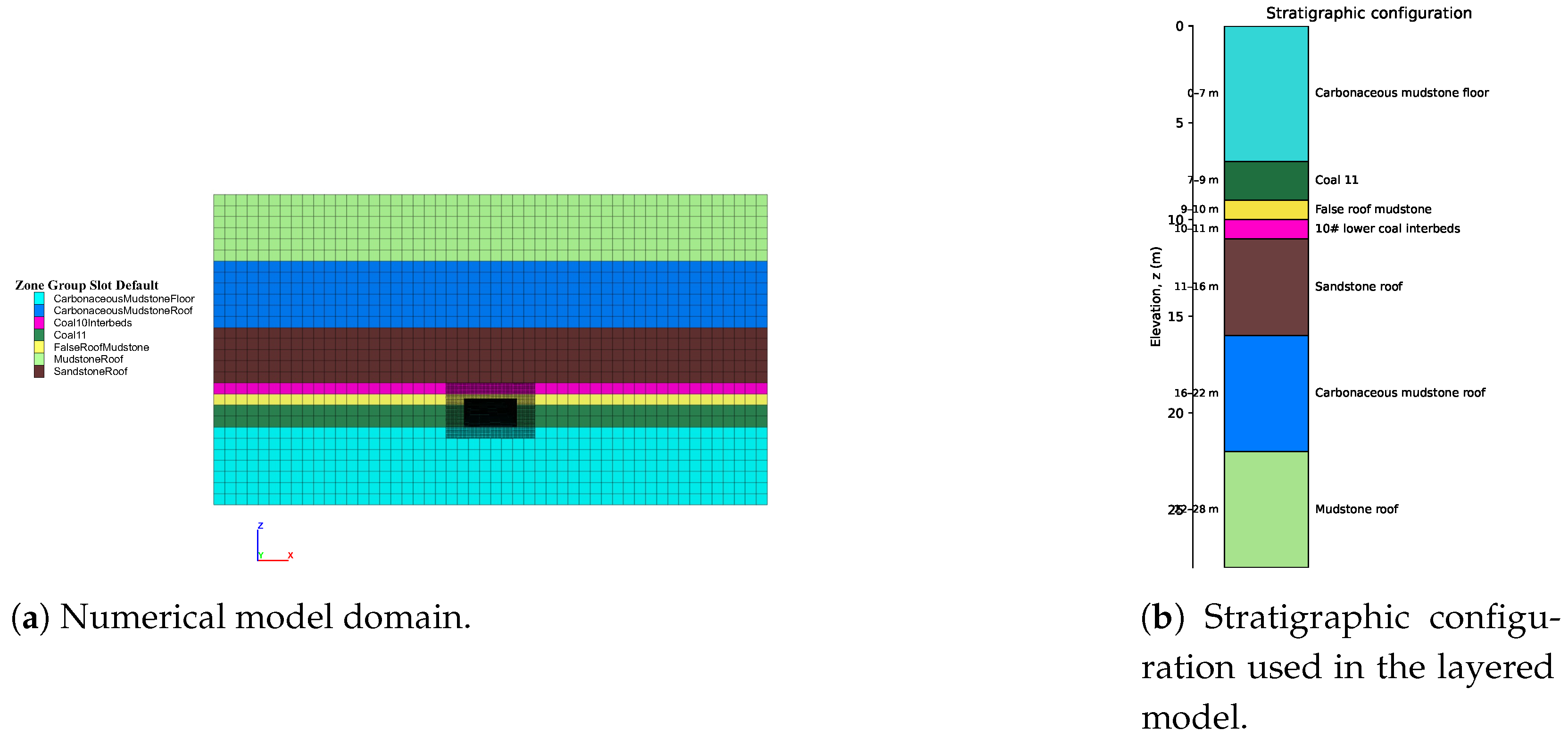
Numerical simulations were performed using FLAC3D 7.0. The FLAC3D model domain was 50 m × 50 m × 28 m. The roadway excavation was positioned at the model center, and the net rectangular section was 4.8 m × 2.6 m. The bottom boundary was fixed in the vertical direction, the lateral boundaries were fixed in the normal direction, gravity loading was applied, and an additional vertical stress of 6 MPa was imposed on the top boundary to represent the overburden effect. The lateral pressure coefficient was taken as 1.2, corresponding to the adopted horizontal-to-vertical stress ratio for the case. The resulting initial stress condition was therefore an equivalent static in-situ stress field rather than a measured three-dimensional stress tensor.
All rock and coal strata were modeled using the Mohr–Coulomb constitutive model, which was selected as an equivalent continuum representation of the layered coal-measure strata. This choice is consistent with the available engineering data, which provide lithology and basic mechanical properties but do not provide a complete mapped discontinuity database. Because detailed fracture surveys, including joint dip, dip direction, spacing, persistence, and discontinuity-set statistics, were not available for the case record, the present model does not explicitly simulate mapped joints or bedding separation surfaces. Instead, it represents the dominant stratigraphic sequence through layered material zoning and acknowledges that the influence of discontinuities is included only indirectly through equivalent strength parameters. The mesh was locally densified around the roadway and the roof-control region to improve the resolution of displacement and stress changes near the excavation. Because the original and optimized support schemes used exactly the same mesh, boundaries, material parameters, and monitoring paths, the comparison emphasizes relative differences between schemes. A full mesh-sensitivity study and explicit discontinuity modeling were not performed and are acknowledged as limitations.
Displacement and stress data were extracted along the central roadway cross section (
m). Roof and floor responses were monitored by
z-direction displacement and
, whereas rib responses were monitored by
x-direction displacement and
. The support system considered in the model was a permanent static reinforcement system composed of roof bolts, rib bolts, and roof cables, as listed in
Table 5. The roof bolts and rib bolts were used to reinforce the shallow fractured zone, while the longer roof cables were used to connect the shallow roof to a deeper bearing horizon. Bolt and cable members were represented by FLAC3D structural cable elements connected to the surrounding rock through grout-bond properties. The adopted structural parameters included an elastic modulus of 206 GPa, a cross-sectional area of
m
2, a yield-tension command parameter of
N, and an applied pretension of
N in the bonded reinforcement segment. In this simplified model, the reinforcement members mainly work in axial tension and transfer load to the surrounding rock through the grout interface; possible shear failure at individual discontinuities, installation deviation, plate-yield behavior, corrosion, and construction-equipment constraints were not explicitly modeled. During post-processing, the axial-force contours of bolts and cables were available only in combined form; accordingly, the shorter support members were interpreted as bolts and the longer ones as cables.
4.2. Stratigraphy and Material Parameters
From bottom to top, the model included carbonaceous mudstone floor, No. 11 coal seam, false-roof mudstone, No. 10 lower coal interbeds, sandstone roof, carbonaceous mudstone roof, and mudstone roof. This bottom-to-top arrangement is consistent in both the model-domain view and the stratigraphic schematic shown in
Figure 4. To improve numerical stability, the dilation angle of each stratum was set to zero. The major lithologies and mechanical parameters used in the FLAC3D model are listed in
Table 6.
In addition to the parameters listed in
Table 6, friction angles of the strata ranged from 24° to 33°, tensile strengths ranged from 0.08 to 0.80 MPa, and the dilation angle was set to 0° for all strata. The zero-dilation assumption was adopted to obtain a conservative and numerically stable representation of post-yield deformation in the relatively weak coal-measure strata.
4.3. Engineering Assumptions for Anchorage-System Selection
To make the support-design assumptions explicit, the anchorage system was interpreted according to the lithologic and loading conditions of the roadway. The weak coal seam and false-roof mudstone require short bolts to improve shallow-rock integrity, while the stronger sandstone roof provides a more favorable horizon for longer bolts and cables to develop anchorage. The roadway support was treated as a permanent static support system under the equivalent in-situ stress field described above. The dominant load direction for roof reinforcement was tensile load along the bolt or cable axis combined with confinement of shallow roof separation, whereas the rib bolts mainly restrained lateral convergence. The embedment length and spacing were checked through the theory-based correction rules so that the final support parameters remained within standard engineering ranges and avoided unconstructible or overly dense/sparse layouts. Environmental effects, dynamic vibration, water-induced weakening, construction equipment, and detailed installation procedures were not explicitly included in the numerical model; these factors are recognized as practical constraints that should be checked before field application.
5. Results and Discussion
5.1. Displacement Response
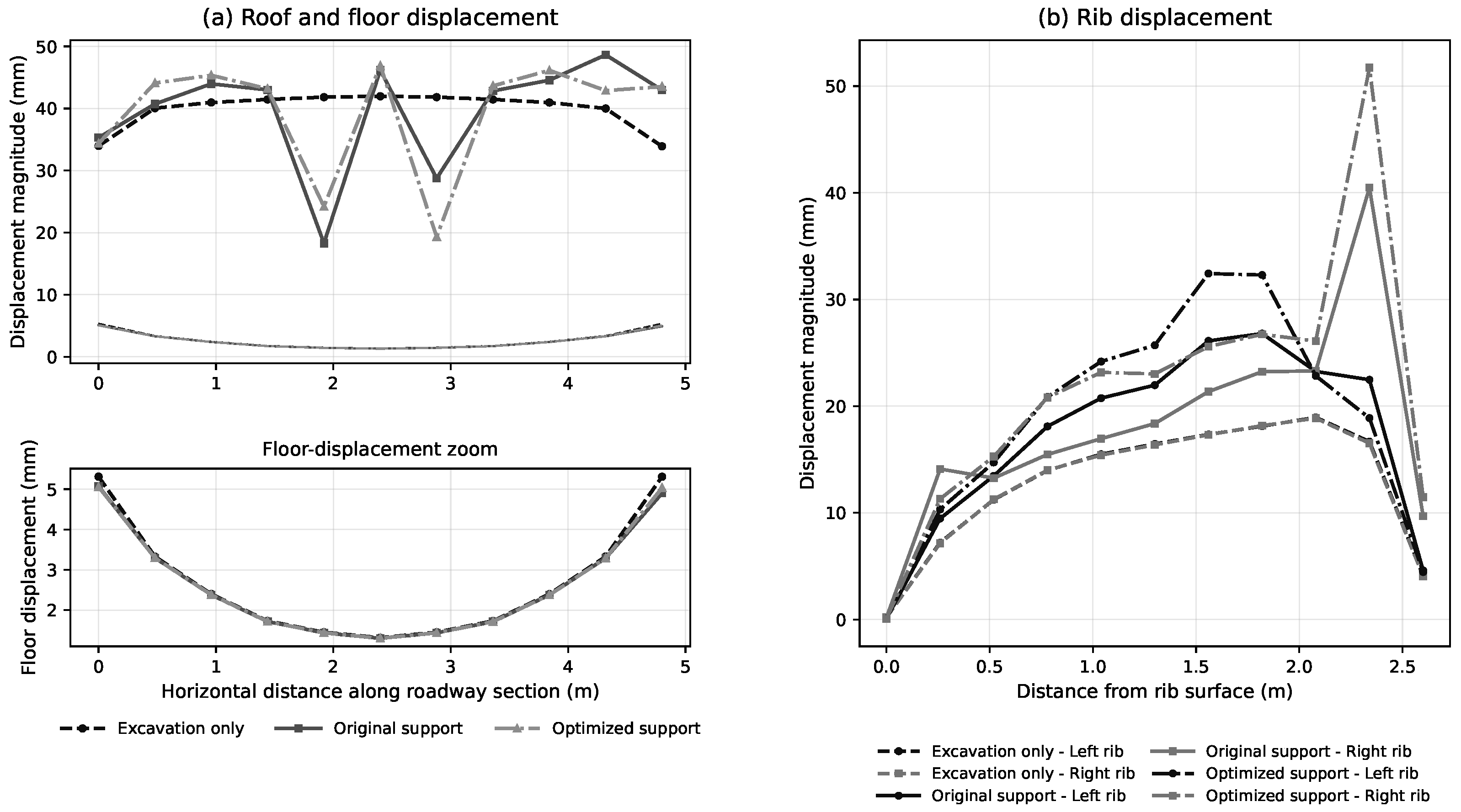
The displacement curves extracted from the central section are shown in
Figure 5. In
Figure 5a, a separate floor-zoom panel is placed below the main roof-and-floor displacement plot because the floor-displacement magnitudes are much smaller than the roof-subsidence values. The optimized scheme reduced the maximum roof subsidence from 48.64 mm to 46.91 mm, corresponding to an absolute reduction of 1.73 mm and a relative reduction of 3.55%. The floor heave changed only slightly, from 5.08 mm to 5.06 mm. Therefore, the improvement should be interpreted as modest rather than substantial. Its value is mainly that it identifies a mechanically interpretable roof-strengthening direction under a controlled single-variable comparison, not that it proves a large global deformation reduction.
The rib response followed a different trend. Under the original support scheme, the maximum displacements of the left and right ribs were 26.80 mm and 40.48 mm, respectively; under the optimized scheme, they increased to 32.42 mm and 51.72 mm. Consequently, the total rib convergence increased from 67.28 mm to 84.15 mm, namely an increase of 16.87 mm or approximately 25.1%. This adverse response weakens any claim of global support improvement. It suggests that the current optimization should be interpreted as a roof-priority strengthening scheme rather than a full-section optimization scheme. The result also indicates that increasing roof-bolt length may redistribute deformation toward the ribs when rib support remains unchanged. A local crossing between the roof-displacement curves can be observed around 2–3 m along the monitoring line. This behavior is interpreted as a local redistribution effect associated with the longer bolt anchoring horizon and the nonuniform transfer of support load near the roof shoulder, rather than a contradiction of the global result, because the maximum roof displacement and the overall roof-subsidence trend remain lower for the optimized scheme.
5.2. Stress Redistribution
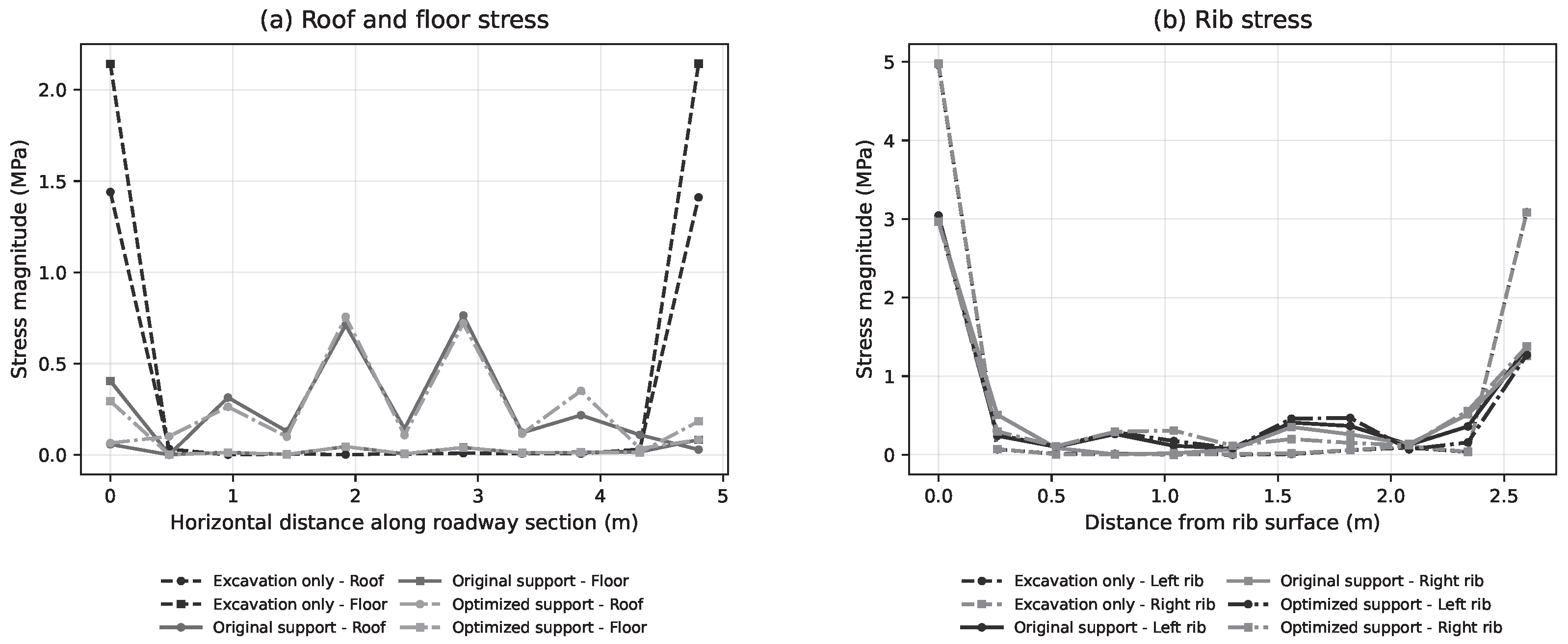
The stress curves are shown in
Figure 6. Along the monitoring path, the optimized scheme reduced the roof stress peak from 0.764 MPa to 0.757 MPa, the floor stress peak from 0.405 MPa to 0.295 MPa, the left-rib stress peak from 3.044 MPa to 2.981 MPa, and the right-rib stress peak from 2.979 MPa to 2.965 MPa. Although these values represent local peaks along the monitoring path rather than full-field extrema, they consistently indicate that the increase in roof bolt length alleviated local stress concentration to a certain extent.
This stress response is consistent with the support mechanism of longer roof bolts. When the bolts extend into more intact and mechanically stronger strata, their load-transfer capacity increases, and the shallow roof separation can be restrained more effectively. However, because the rib-bolt system was unchanged, the additional constraint was insufficient to suppress rib deformation.
5.3. Integrated Comparison of Key Indicators
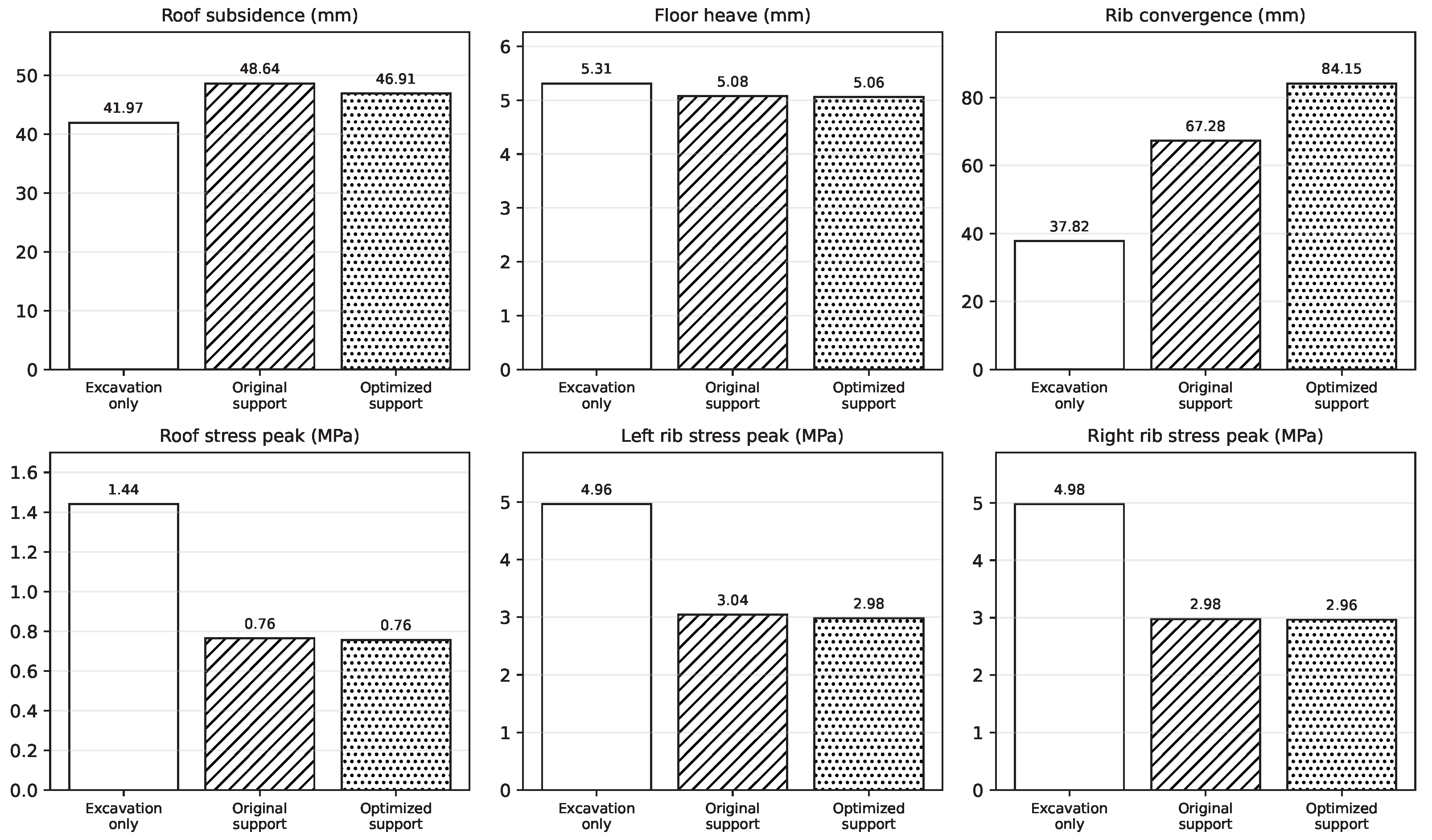
Figure 7 and
Table 7 summarize the key indicators. The optimized scheme performed better in roof control but worse in rib convergence. Therefore, the numerical verification does not support a generalized conclusion that the machine-learning-guided scheme is globally superior to the original scheme for all indicators. Instead, it shows that the proposed workflow can identify a more targeted improvement direction for the most critical component of the support system, namely the roof.
This distinction is important for engineering interpretation. In the present workflow, the machine learning model predicts only roof bolt-cable parameters, whereas the rib-bolt configuration is retained by rule-based continuation from the field scheme. The approach is therefore not intended as a full-section redesign method. The FLAC3D results are consistent with this methodological boundary: roof-oriented optimization improves roof response, but rib behavior still requires dedicated modeling and joint optimization in future work.
5.4. Engineering Implications
The Sanxia 1008 material roadway of Fucun Mine provides an external consistency check rather than a full independent numerical validation. For this case, the machine learning-theory workflow produced roof-support parameters that were close to the previously adopted field-adjusted scheme. This agreement suggests that the proposed workflow can reproduce a reasonable engineering tendency in a case outside the main FLAC3D simulation. However, because only one complete numerical verification was performed, the cross-case applicability of the method should be considered preliminary.
For the 11104 return-air roadway, the combined evidence from machine learning, engineering constraints, and FLAC3D indicates that extending the roof bolt length from 2.00 m to 2.64 m has clear mechanical interpretability: longer bolts can reach a more stable anchorage horizon and improve shallow roof integrity. From a practical perspective, this modification increases the bolt length by 0.64 m, or approximately 32% relative to the original 2.00 m bolt. Because the diameter, spacing, cable layout, and rib-bolt scheme are unchanged, the additional cost and construction workload are mainly associated with longer drilling and additional bolt material. Considering that the roof-subsidence reduction is only 3.55% and rib convergence worsens, the optimized scheme should not be directly promoted as a final field design without further rib-support adjustment, cost checking, and field monitoring. It is more appropriate to regard the result as a roof-priority recommendation that identifies the direction of roof reinforcement.
The current results also define the boundary of the workflow. A more complete method should include dedicated rib-support targets, joint roof-rib optimization, explicit discontinuity characterization, field monitoring calibration, and sensitivity analyses for pretension, spacing, bolt/cable length, lateral pressure coefficient, and rock-mass mechanical properties. Such analyses are necessary to test the robustness of the present conclusions and to determine whether the observed roof-benefit/rib-penalty pattern persists under broader parameter variation. With these extensions, the present workflow may evolve from a roof-priority optimization tool into a full-section support optimization framework.