Article

Mechanism of Uplift in Black Shale Fill Subgrade During Operational Phase: Integrating Field Monitoring with Numerical Simulation
1
China Railway Siyuan Survey and Design Group Co., Ltd., Wuhan 430063, China
2
Faculty of Geosciences and Engineering, Southwest Jiaotong University, Chengdu 611756, China
3
Engineering Technology Research Center of Ecological Mitigation of Geohazards in Tibet Plateau Transportation Corridors, Chengdu 611756, China
*
Author to whom correspondence should be addressed.
Appl. Sci. 2026, 16(10), 4705; https://doi.org/10.3390/app16104705
Submission received: 30 January 2026 / Revised: 26 April 2026 / Accepted: 2 May 2026 / Published: 9 May 2026
(This article belongs to the Special Issue Applied Structural Health Monitoring in Civil Engineering)

Abstract

The K166 embankment of the railway connecting Zhangjiajie to Huaihua experienced persistent uplift deformation during the operation state, posing a threat to traveling safety. This study systematically investigated the underlying mechanism through an integrated approach combining field monitoring, laboratory testing, and numerical simulation. Monitoring data confirmed continuous uplift progression. Laboratory analyses revealed that the oxidation of pyrite in the black shale fill generated an acidic environment, triggering acid-driven chemical reactions that caused significant expansion of the fill material. Numerical modeling successfully reproduced the deformation pattern. More importantly, a quantitative link between laboratory-scale expansion and field-scale uplift was established through equivalent parameter inversion. The results indicate that increasing the depth of replacement with non-expansive fill material effectively mitigates foundation uplift, and provides a basis for quantitative evaluation of remediation strategies. Furthermore, this effect becomes more pronounced as the replacement depth increases. It is concluded that in areas with black shale fill, monitoring environmental chemical conditions is essential, and remediation efforts should focus on controlling pyrite oxidation. This work provides both theoretical and practical foundations for addressing similar embankment failures and offers a simplified analytical framework for engineering predictions of uplift under varying conditions.

1. Introduction

The long-term stability of high-speed railway subgrades is essential for ensuring operational safety and ride comfort [1,2,3]. Subgrade engineering typically involves both foundation and fill components, with the engineering properties of the fill layer playing a decisive role in the overall structural performance [4,5,6]. From the perspective of sustainable development and ecological conservation, embankment fill materials generally follow the principle of utilizing locally available resources. While this approach reduces project costs, it also places greater demands on the scientific selection of fill materials [7,8,9]. This is especially critical for high-speed railways, where stringent standards govern post-construction settlement and differential deformation. Typically, specifications limit subgrade settlement to no more than 15 mm, as even minor deformations can compromise track smoothness [10,11]. Therefore, assessing the suitability of fill materials has become a crucial issue in high-speed railway construction.
In studies of subgrade deformation, the deformation mechanisms of fill materials and their long-term performance evolution have received insufficient attention compared to foundation settlement issues [12,13]. Traditional research has predominantly focused on deformation under mechanical loading, often neglecting deterioration caused by interactions between fill materials and environmental factors during operation [14,15,16]. Since fill materials are sourced directly from the surrounding environment of the railway line, they are continuously exposed to water, heat, and chemical agents during long-term operation. These environmental factors can trigger significant water–rock interactions [17,18,19]. These interactions may cause irreversible changes in fill properties, leading to typical failures such as frost heave and chemical expansion [20,21]. Therefore, investigating the long-term performance of fill materials while considering the coupled effects of water, thermal, mechanical, and chemical fields is of great theoretical importance for preventing and controlling subgrade failures.
Among various specialized fill materials, research on black shale fill rich in active minerals such as pyrite remains particularly limited. Under specific hydrochemical conditions, this material is prone to oxidative expansion, causing persistent uplift deformation in the subgrade and posing a severe threat to the structural integrity of ballastless track systems [22,23,24]. However, the quantitative relationship between oxidation-related chemical processes, laboratory-observed expansion behavior, and field-scale uplift evolution has not been clearly established. Previous studies have demonstrated that using an equivalent thermal expansion approach to represent chemically induced long-term swelling is a practical and acceptable engineering simplification [25,26]. Addressing this engineering challenge, this study investigates the black shale fill embankment at the K166 section of the Zhangjiajie-Huaihua Railway. Through 22 months of field deformation monitoring, it systematically reveals the spatiotemporal progression of embankment uplift. Subsequently, this study combined laboratory tests with numerical simulations to elucidate the expansion deformation mechanism of black shale fill at different scales. The laboratory tests included X-ray diffraction (XRD) analysis for mineral composition, swelling rate tests under different chemical conditions, and water chemistry analysis of the leachate. The primary contribution of this study lies in establishing a quantitative and multi-scale framework that integrates field observations, mechanism-oriented laboratory experiments, and equivalent parameter inversion to interpret the long-term uplift of black shale fill subgrades. This approach provides a practical method to quantitatively correlate pyrite oxidation, secondary mineral formation, and laboratory-measured expansion with field-scale uplift deformation of the subgrade. The overall research framework of this study comprises field monitoring, laboratory verification, numerical simulation, and mechanism interpretation, forming a comprehensive technical approach that spans from phenomenon identification to mechanism analysis and engineering evaluation. Furthermore, simplified analytical expressions have been developed to directly estimate uplift deformation under various environmental conditions and replacement depths, thereby extending the applicability of the results for engineering predictions.

2. Geological Conditions and Field Monitoring Results

Since the railway began operation in December 2021, the track section between K166+450 and K166+530 on the Zhangjiajie-Huaihua Railway has exhibited persistent subgrade uplift deformation, posing a serious threat to both track smoothness and operational safety. The primary affected section under investigation is located within Fenghuang County (Figure 1), Xiangxi Tujia and Miao Autonomous Prefecture, Hunan Province, in an eroded hilly terrain characterized by significant topographical undulations. Engineering geological investigations reveal that this area is part of the South China Fold Belt in a tectonic context. The embankment fill material primarily originates from nearby borrow pits, where the strata belong to the Huaqiao Formation (∈2h) of the Middle Cambrian Series. The lithology predominantly consists of limestone interbedded with black shale. Notably, these black shales frequently contain abundant pyrite (FeS2) nodules or banding, which constitute the primary source of subgrade failures [22]. The limestones typically exhibit a cryptocrystalline structure with medium-thick bedding and well-developed joints, whereas the black shales are thin-bedded, soft, and prone to weathering and fragmentation [27].
Field uplift monitoring was conducted using single-point settlement gauges (JMDL-47XXAT/ADT) manufactured by Changsha Jinma Measurement and Control Technology Co., Ltd., Changsha, China. These instruments have an accuracy of 0.5% full scale (FS) and a resolution of 0.01 mm. Measurements were recorded three times daily. The monitoring network comprised seven representative cross-sections, each equipped with settlement gauges installed at depths of 0.4 m, 1.0 m, 1.5 m, 2.0 m, 2.5 m, 3.5 m, and 5.0 m, along with four additional single-point settlement gauges deployed at separate sections for supplementary observations.
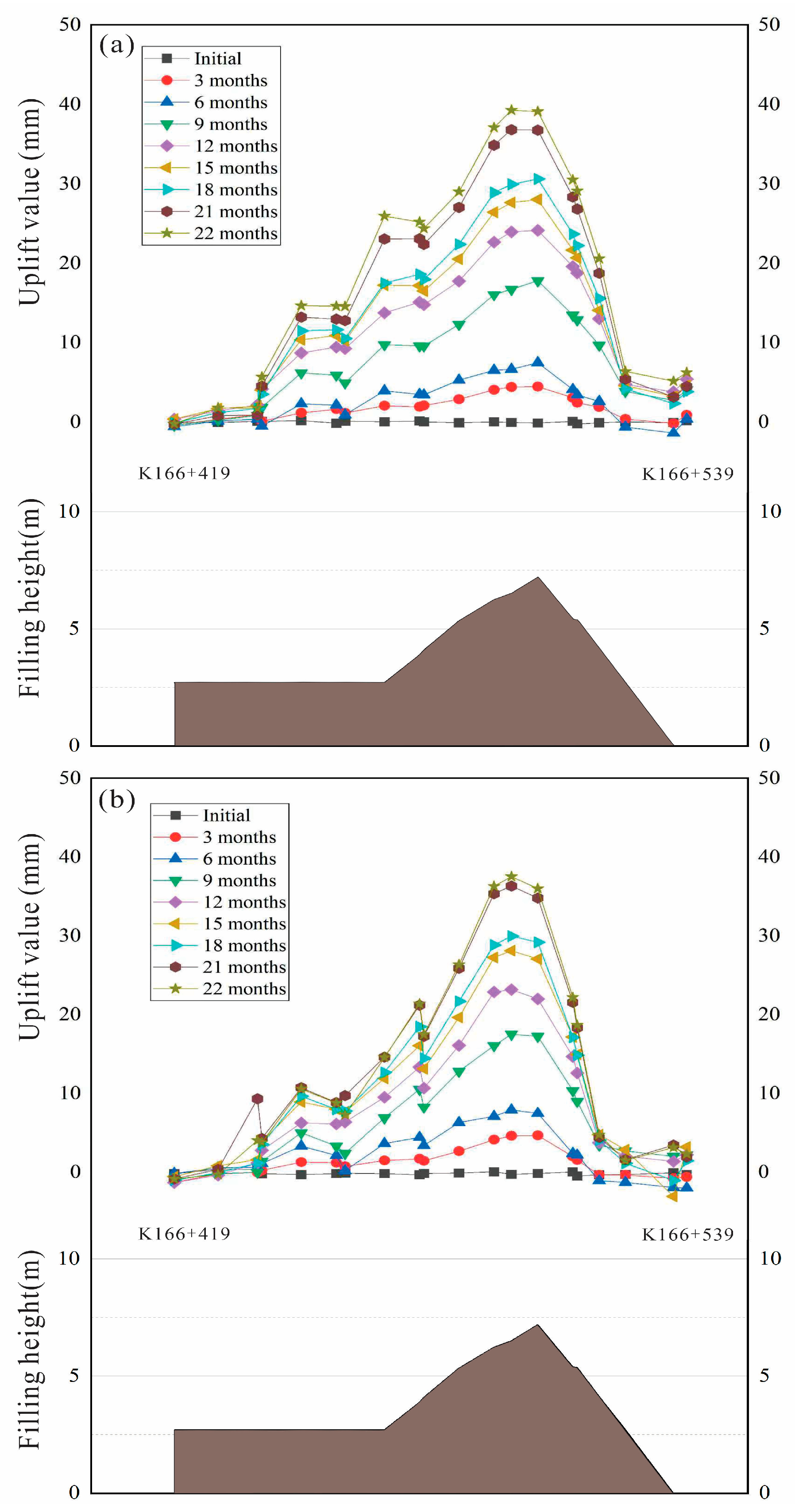
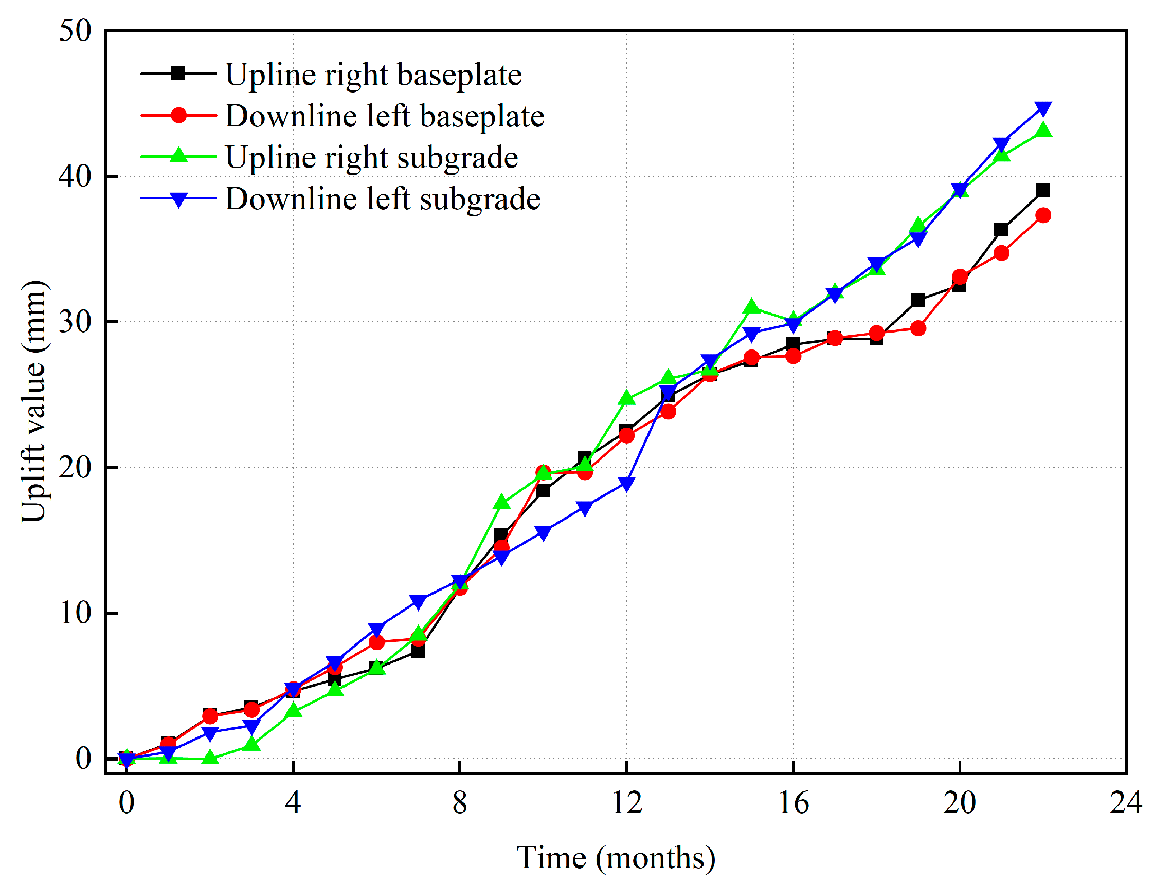
Detailed field monitoring data clearly documented the progression of deformation (Figure 2). By November 2023, the cumulative maximum uplift at K166+498 on the downline had reached 69 mm, with the corresponding position on the upline registering 67 mm. Crucially, no convergence trend was observed during the monitoring period.
During the final eight months of monitoring, approximately 15 mm of additional uplift occurred both downstream and upstream, with the monthly average uplift rate stabilizing at around 1.5 mm (Figure 3). This persistent deformation pattern closely aligns with the mechanism whereby pyrite within the black shale undergoes oxidation and hydrolysis under specific hydrochemical conditions within the subgrade, generating expansive sulfate minerals such as pyrite sulfate and gypsum. Given the fill thickness ranging from 2.3 to 11 m within this uplifted section, internal expansive stresses accumulated persistently, ultimately manifesting as pavement elevation. These systematic monitoring outcomes provide a robust foundation for elucidating the underlying failure mechanisms.

3. Uplift Mechanism

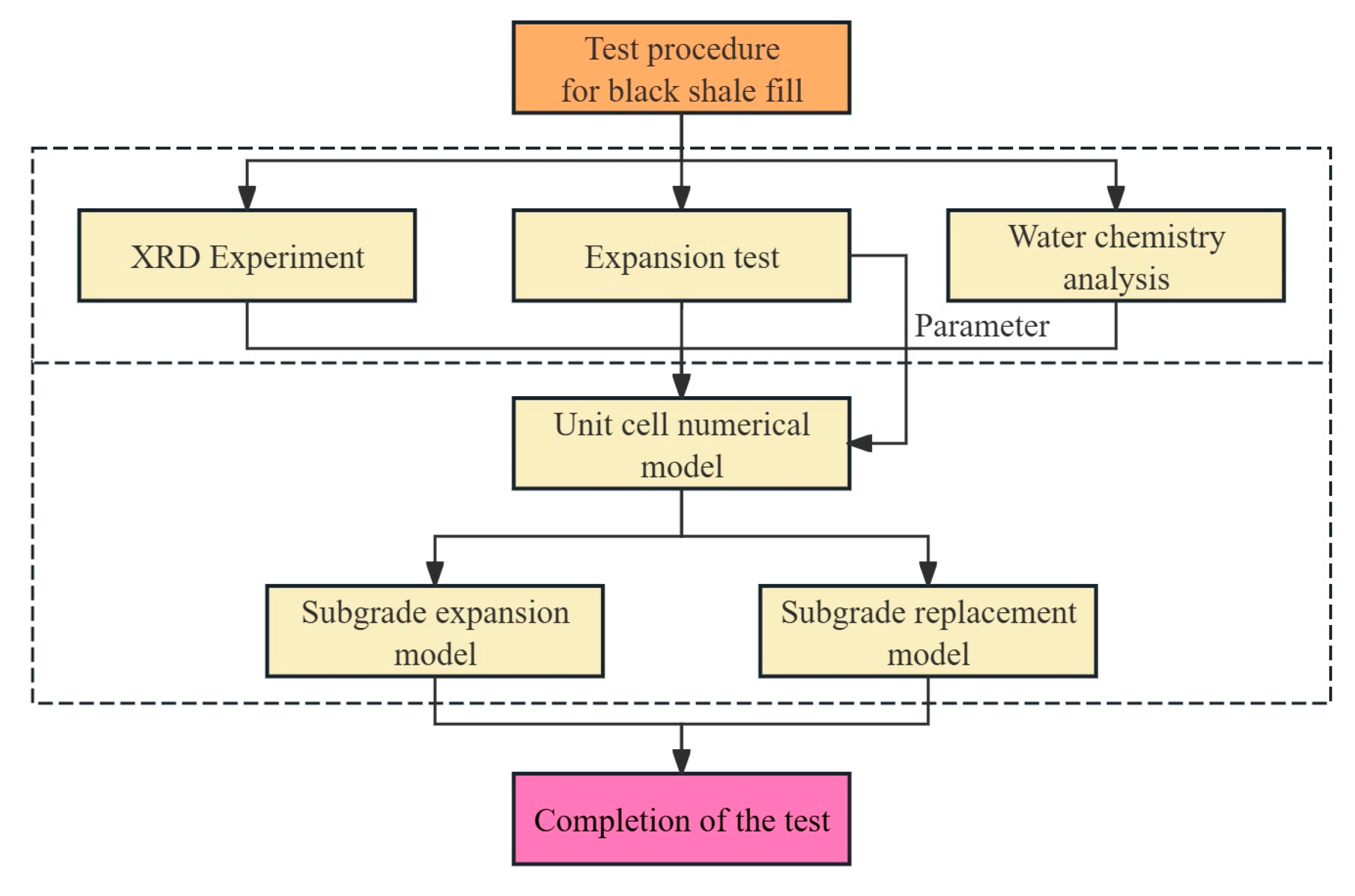
To clarify the uplift mechanism of the black shale fill subgrade, a systematic research framework was established. This study integrates laboratory experiments and numerical simulations. The mineral composition was first identified using X-ray diffraction (XRD) analysis. Expansion tests and water chemistry analyses were then conducted to reveal the chemical processes and volumetric behavior of the fill material. Based on these results, a unit cell numerical model was developed to determine the equivalent expansion coefficients. Finally, full-scale subgrade models were constructed to evaluate the uplift behavior and the effectiveness of replacement measures. The overall research procedure is illustrated in Figure 4.

3.1. Laboratory Test

3.1.1. Mineral Composition Analysis

To elucidate the compositional evolution of fill material under operational conditions and clarify the chemical mechanisms driving its uplift deformation, this study employed systematic mineralogical analysis using X-ray diffraction (XRD) on uplift-deformed roadbed fill material and undisturbed rock samples from the borrow pit. Mineral analysis was performed using X-ray diffraction (XRD; Rigaku MiniFlex, Tokyo, Japan) on randomly oriented powder mounts with Cu Kα radiation at 20 kV and 50 mA, over a scan range of 3° to 40°. The mineral contents listed in Table 1 should be considered approximate proportions. According to the manufacturer, the instrumental repeatability for representative MiniFlex-series measurements is better than 0.2 standard deviations.
This study selected filler samples from locations exhibiting varying deformation characteristics within the uplift section, along with undisturbed fresh black shale samples from the soil extraction site. Qualitative and semi-quantitative analyses were performed using an X-ray diffractometer. The results indicate that all samples are dominated by relatively stable minerals, including quartz (SiO2), feldspar, calcite (CaCO3), and dolomite (CaMg(CO3)2). In addition, pyrite (FeS2), gypsum (CaSO4·2H2O), and clay minerals such as illite and chlorite were identified in the black shale and fill samples. The specific mineral mass percentages for each sample are detailed in Table 1. These findings provide direct mineralogical evidence supporting the subsequent analysis of a composite subgrade uplift mechanism centered on pyrite oxidation, potentially accompanied by water absorption and expansion of clay minerals.

3.1.2. Expansion Test

To quantitatively assess the volumetric expansion potential of subgrade fill materials under specific environmental conditions and thereby elucidate the intrinsic mechanisms of their uplift deformation, this study conducted unloaded expansion rate tests on subgrade soil samples collected from the field. The tests aimed to compare the expansion characteristics of the fill material under natural hydrological conditions versus oxidized conditions.
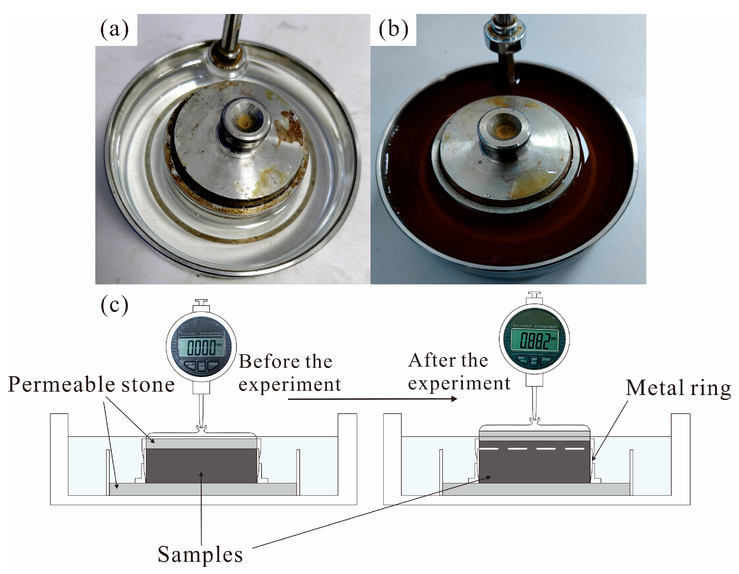
The test materials were ground in a ball mill to a particle size smaller than 150 mesh (less than 0.1 mm) to eliminate particle size effects and ensure complete reaction. The tests were conducted in strict accordance with the Standard for Geotechnical Test Methods (GB/T 50123-2019) [28]. Distilled water was used to simulate natural conditions, reflecting physical water absorption and expansion caused by natural precipitation or groundwater infiltration. In contrast, a 0.05 mol/L ferric chloride (FeCl3) solution was introduced as an oxidizing agent to represent the conditions associated with pyrite weathering. The pH of this solution is approximately 1, which is comparable to the acidic environment observed during pyrite oxidation and weathering [29]. The expansion test under distilled water and 0.05 mol/L FeCl3 solution conditions are shown in Figure 5.
The expansion tests were conducted in triplicate for each chemical condition. The differences among the repeated measurements were minimal, and the expansion rates reported below represent the average values of the three tests.
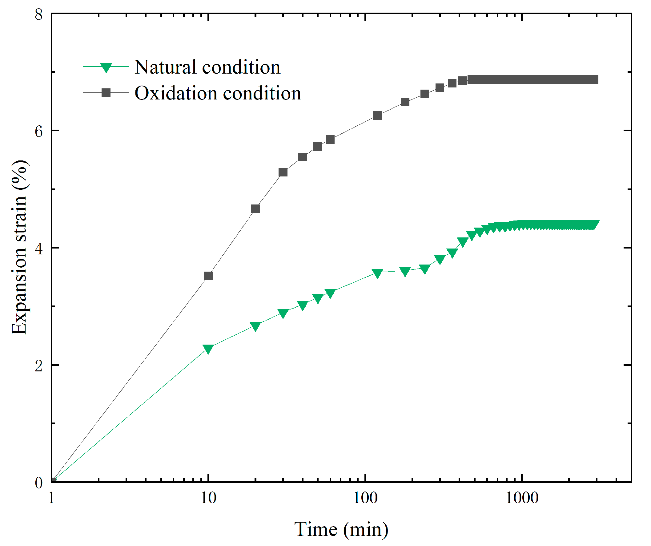
The experimental results (Figure 6) clearly demonstrate a significant difference between the two conditions. Under distilled water conditions, the expansion rate of the filler material was 4.41%, whereas under simulated oxidation conditions using FeCl3 solution, the expansion rate increased markedly to 6.87%.

3.1.3. Water Chemistry Analysis

Although expansion data directly reflect the final outcome of volume changes in fillers under varying chemical environments, this metric alone is insufficient to accurately elucidate the underlying mechanisms of differential expansion. The expansion of shale fillers represents the macroscopic manifestation of a complex interplay of microscopic physicochemical processes, including mineral dissolution, ion exchange, and the crystallization and precipitation of new phases. Different dominant reaction pathways can produce similar patterns in the macroscopic expansion timeline.
To overcome this limitation and elucidate the chemical mechanisms underlying expansion induced under natural and oxidizing conditions, this study conducted systematic hydrochemical analyses of the residual solutions collected after completion of the expansion tests (Table 2). The final pH values of the solutions under distilled water and 0.05 mol/L FeCl3 conditions were approximately 5.6 and 3.5, respectively. Before analysis, the solution samples were filtered, appropriately diluted, and acidified with nitric acid to prevent precipitation. The concentrations of major dissolved elements in the post-test solutions were determined using inductively coupled plasma mass spectrometry (ICP-MS; iCAP TQ, Thermo Fisher Scientific, Waltham, MA, USA). The main instrumental parameters included an RF power of 1550 W, a nebulizer gas flow rate of 1.0749 L/min, and KED mode.
By precisely measuring and comparing the concentrations and speciation of key elements (such as S, Fe, Ca, Mg, K, Si, etc.) in the solutions, the study aimed to trace the oxidation and dissolution processes of pyrite, identify evidence for the formation of secondary sulfate minerals (such as potassium iron sulfate and gypsum), and evaluate the ion exchange and dissolution behavior of clay minerals. This analysis serves as a crucial link between the macroscopic swelling phenomenon and the microscopic chemical reactions. For consistency with standard water chemistry reporting, the dissolved concentrations in Table 2 are expressed in density units (mg/L).

3.2. Numerical Model

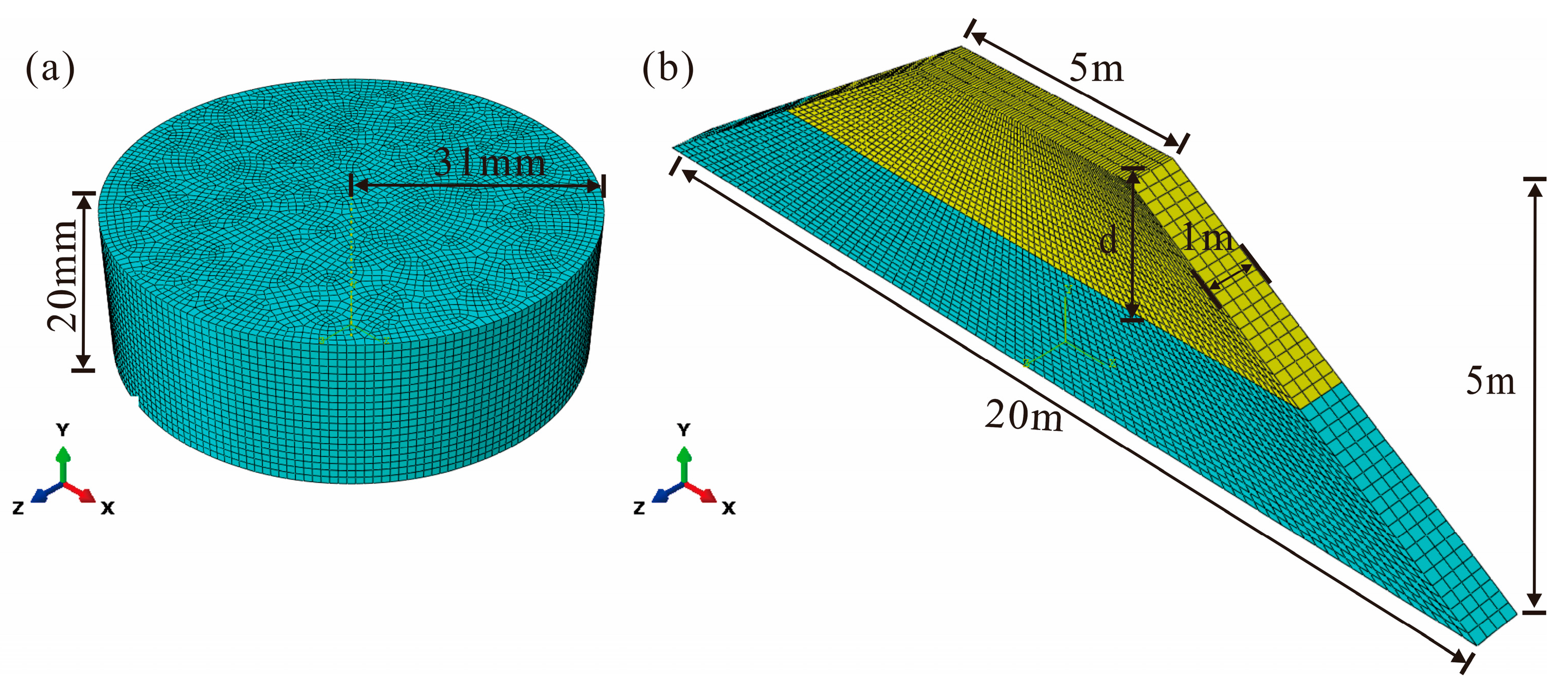
To quantitatively evaluate the heave deformation characteristics of roadbeds under various environmental conditions and to optimize engineering remediation strategies, this study developed a three-dimensional finite element model in ABAQUS (6.14) to study the expansion characteristics. Two representative working conditions were considered: natural environment and oxidizing environment. The top boundary of the model is free, while the bottom boundary is fixed. The side boundaries simulate lateral confinement experiments by restricting displacement in the horizontal direction. The finite element meshes of both the unit cell model and the full-scale subgrade model are shown in Figure 7. Different filling displacement depths are denoted by d in Figure 7b. In this study, the equivalent expansion coefficient was used to represent the combined chemical swelling effect of black shale fill, while physical temperature variations and moisture changes were not modeled as independent variables. In the numerical simulations, an implicit iterative solution scheme was employed.
The critical input parameters for the model, particularly the expansion coefficient governing volume expansion, were determined through unit cell inversion analysis. First, a cylindrical unit cell model matching the laboratory test dimensions (radius 31 mm, height 20 mm) was established. By adjusting the expansion coefficient, the simulated expansion curve was aligned with the laboratory unloaded expansion rate test results under two operating conditions, maintaining the error within 10%. The validated expansion coefficient was then applied to the expansion analysis of the full-scale subgrade model.
The subgrade model was constructed based on the actual subgrade cross-sectional dimensions, featuring a trapezoidal shape with a top width of 5 m, a base width of 20 m, and a height of 5 m. The longitudinal section of the model was assigned a thickness of 1 m to represent a typical cross-section. The model utilized a hexahedral-dominated mesh, uniformly divided into 10 layers along the height. The material constitutive behavior was modeled using the Mohr–Coulomb elastic–plastic model, with parameters specified according to the Railway Subgrade Design Specification (TB 10001-2016) [30] and relevant geological investigation reports [31]. The model’s base was fixed, with lateral displacement restricted on both sides, and self-weight effects (g = 9.8 m/s2) were included. Relevant parameters are shown in Table 3.
It should be noted that the current model represents chemical expansion as equivalent expansion.

3.2.1. Numerical Model Under Natural and Oxidizing Conditions

In the inversion analysis of the unit cell model, material parameters for subsequent full-scale simulations were determined by adjusting the coefficient of thermal expansion to align the simulated displacement with corresponding laboratory test results under operational conditions. In this study, the thermal expansion formulation was employed as an equivalent numerical approach to simulate chemically induced uplift, rather than purely temperature-driven deformation [25,26]. Given the thin-bedded nature and relatively uniform structural characteristics of black shale, it was treated as a homogeneous medium for the expansion simulation. Accordingly, pore structure and moisture content were not included as independent variables in the model [32,33,34].
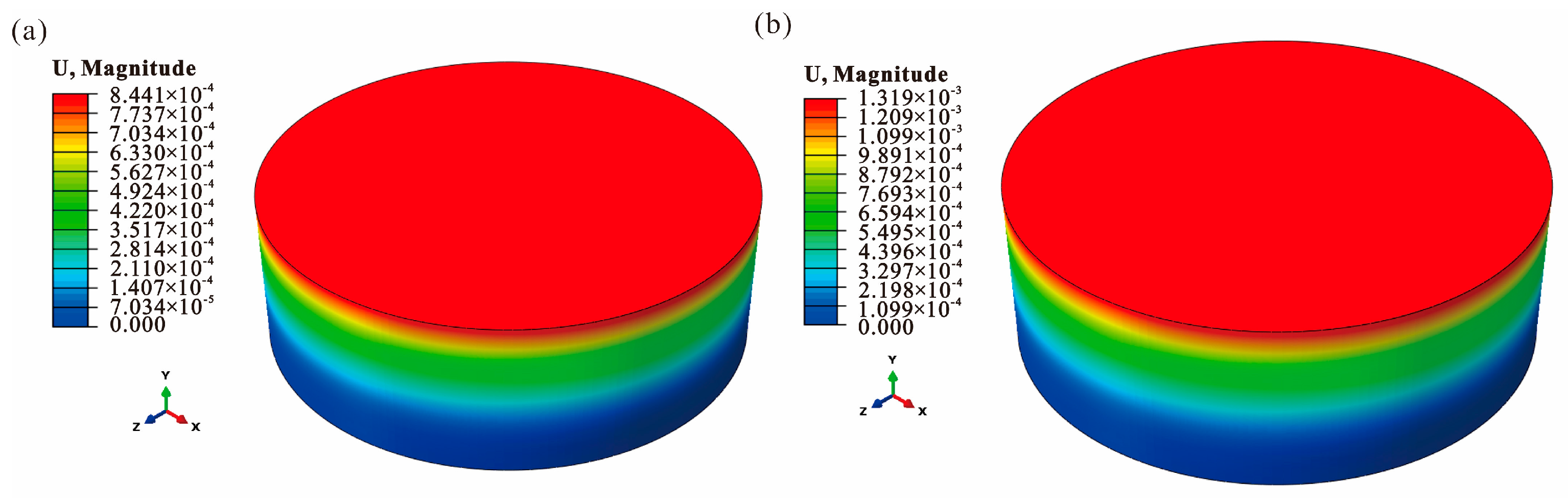
Specifically, a cylindrical unit cell model with the same dimensions as the specimens used in the unloaded expansion tests described in Section 3.1.2 was first developed. The coefficient of thermal expansion was iteratively calibrated until the simulated expansion displacement closely matched the laboratory measurements within a 10% margin. This calibrated coefficient was then adopted as the equivalent expansion parameter under the corresponding field conditions and subsequently applied to the full-scale subgrade model to predict the uplift deformation. Under natural conditions, the simulated displacement (0.844 mm) closely matched the test value (0.882 mm), establishing a coefficient of thermal expansion of 1.6 × 10⁻⁵ K−1 (Figure 8a). Under oxidizing conditions, the comparison of the simulated displacement (1.319 mm) with the test value (1.374 mm) validated the appropriateness of the adopted expansion coefficient of 2.5 × 10⁻⁵ K−1 (Figure 8b). The validated expansion coefficient was then directly applied to full-scale subgrade expansion simulations under the corresponding operating conditions. The agreement between the simulated and measured displacements under the two calibration conditions yielded an R2 value of 0.963 and an RMSE of 0.047 mm, indicating that the equivalent expansion model can accurately reproduce the observed deformation response at the specimen scale.
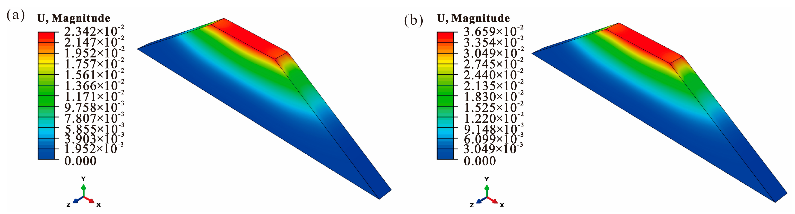
Under both operational conditions, the expansion coefficients validated through unit cell modeling were incorporated into the subgrade model to calculate the annual expansion displacement field for unfilled material conditions. Under natural conditions, the maximum displacement at the center of the subgrade surface reached 23.42 mm (Figure 9a); under oxidizing conditions, this value significantly increased to 36.59 mm (Figure 9b), indicating that oxidation substantially exacerbated material expansion. The displacement field exhibits a continuous spatial distribution pattern, increasing from the base upward and decreasing from the centerline toward the toe of the slope. This pattern aligns with the model’s boundary constraints. The numerical results corroborate the laboratory testing conclusions, jointly revealing that pyrite oxidation is the primary chemical mechanism causing significant uplift deformation in the field subgrade. Moreover, the simulated surface uplift under natural conditions was 23.42 mm, which closely agrees with the monitored uplift value of 25.17 mm shown in Figure 2, further supporting the reliability of the numerical model.

3.2.2. Numerical Model for the Replacement Depth of Different Black Shale Fill Materials

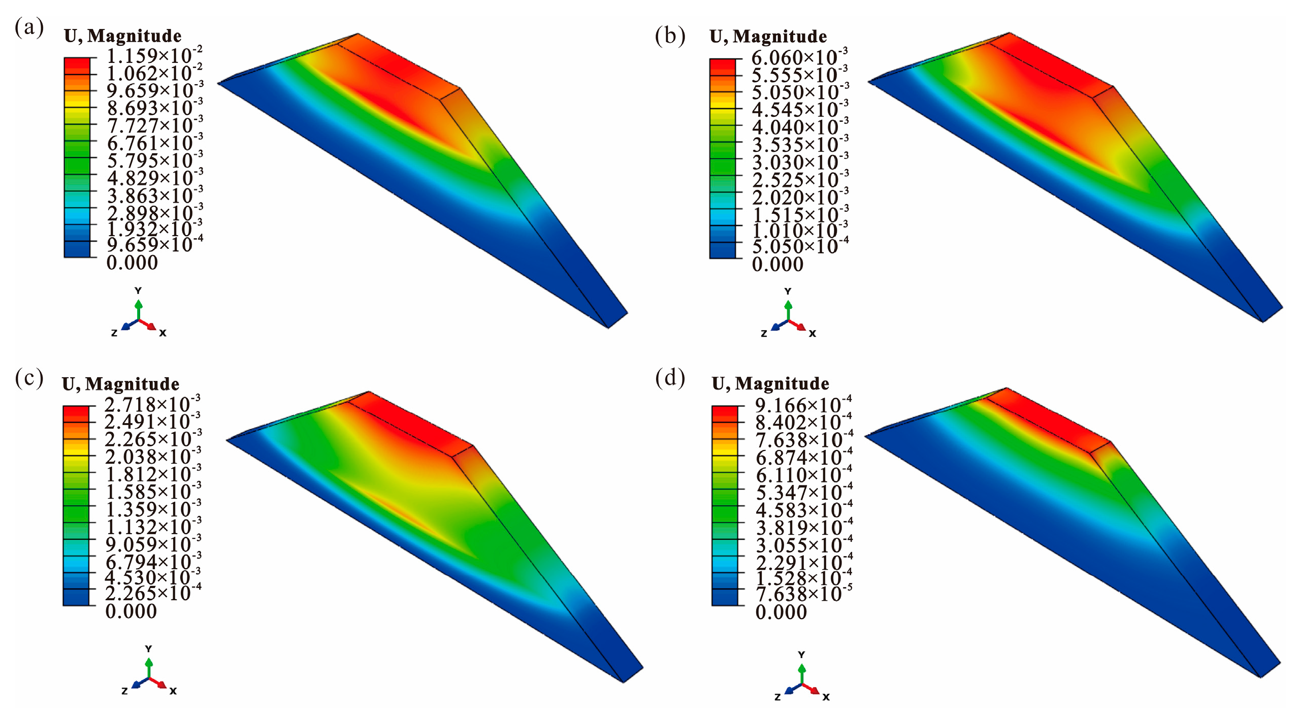
To evaluate the effectiveness of engineering remediation measures (replacement fill) in mitigating uplift deformation, this study systematically simulated the expansion behavior of embankments at various replacement depths. The subgrade model used in this section is identical in scale, geometry, and dimensions to that described in Section 3.2.1. The simulations used expansion coefficients derived from the inversion calibration of the unit cell model. Under natural conditions, the adopted coefficient was 1.6 × 10⁻⁵ K−1. These coefficients were subsequently applied to the full-scale subgrade models under the corresponding environmental conditions. Five key replacement scenarios using black shale fill material were established, with replacement thicknesses of 0 m, 1.5 m, 2.5 m, 3.5 m, and 5 m, covering engineering approaches from localized treatment to complete replacement. Representative displacement contours of the subgrade model for replacement depths of 1.5 m, 2.5 m, 3.5 m, and full replacement are shown in Figure 10a–d, respectively, while the unreplaced reference case corresponds to Figure 9a.
By extracting vertical displacement data along the centerline of the roadbed under various operating conditions, as shown in Table 4, the effectiveness of the replacement fill material can be clearly quantified. Numerical simulation results indicate that increasing the replacement depth generally reduces the ultimate uplift deformation of the subgrade, particularly at the subgrade surface. However, slight local non-monotonic variations may occur at certain intermediate depths. Specifically, greater replacement thickness substantially reduces both the maximum expansion displacement at the subgrade surface and the depth-wise extent of expansion influence. This pattern holds consistently under natural conditions, providing clear evidence of the effectiveness of increasing the replacement depth of fill materials to isolate or mitigate expansive black shale fill. These findings offer a solid quantitative basis for optimizing remediation strategies.

4. Discussions and Conclusions

4.1. Causes of Uplift: The Influence of Oxidation

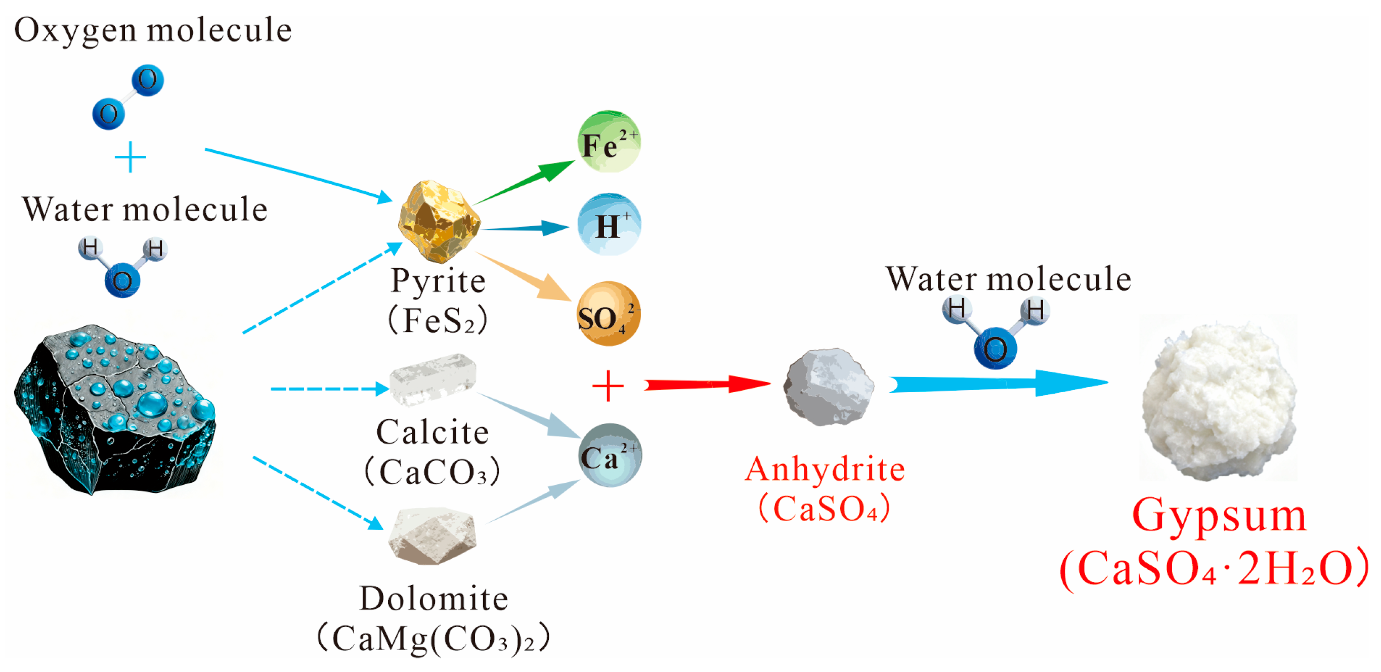
Based on the results of the water chemistry analysis (Table 2) and the mineral oxidation mechanism diagram (Figure 11), this subsection systematically explains that the chemical chain reaction centered on pyrite oxidation is the primary cause driving the uplift deformation of black shale filler subgrades. Under simulated natural conditions involving distilled water immersion, elemental leaching concentrations remained extremely low, with only minimal dissolution occurring in the fill material. The corresponding volumetric expansion rate was merely 4.41%, confirming that the chemical reactivity of the fill material is suppressed in environments lacking oxidizing agents.
However, under simulated aerobic conditions using a 0.05 mol/L FeCl3 solution, the concentrations of various ions in the leachate increased by several orders of magnitude. As shown in Figure 6, this dramatic chemical transformation began with a self-catalyzed oxidation cycle. Initially, pyrite (FeS2) oxidized in the presence of oxygen [35], producing Fe2+ and SO42− ions and releasing H+ ions, thereby initiating acidification, as depicted in Equation (1):
2 F e S 2 + 7 O 2 + 2 H 2 O 2 F e 2 + + 4 S O 4 2 + 4 H +
Subsequently, the generated Fe2+ can be further oxidized to the strong oxidizing agent Fe3+ in an oxygen-rich environment [36], as shown in Reaction (2):
4 F e 2 + + O 2 + 4 H + + 4 F e 3 + + 2 H 2 O
The newly generated Fe3+ ions, in turn, oxidize pyrite more efficiently, as shown in Equation (3) [36]. This cycle significantly accelerates the production of sulfate and hydrogen ions, serving as the key driving force behind the strong acidification of the solution.
F e S 2 + 14 F e 3 + + 8 H 2 O 15 F e 2 + + 2 S O 4 2 + 16 H +
The resulting acidic environment significantly accelerated the decomposition of other minerals within the fill material [37,38]. The marked increase in calcium and magnesium concentrations indicates substantial acid dissolution of carbonate minerals, such as calcite and dolomite, as shown in Equations (4) and (5) [39,40]. This process not only compromised the original structural integrity of the fill material but also supplied the essential calcium and sulfate ions required for the formation of secondary expansive minerals, such as gypsum.
C a C O 3 + H + C a 2 + + H C O 3
C a M g C O 3 2 + 2 H + C a 2 + + M g 2 + + 2 H C O 3
The Ca2+ ions released during dissolution combine with the abundant SO42− ions produced by prior oxidation reactions, initially forming anhydrite (CaSO4). In the groundwater environment, anhydrite undergoes further hydration, transforming into gypsum dihydrate (CaSO4·2H2O). This process involves significant volume expansion, which is the direct physicochemical mechanism responsible for filler swelling. Under oxidizing conditions, pyrite can produce gypsum and other secondary minerals, leading to volumetric expansion of the fill material [41,42]. The reaction is shown in Equations (6) and (7):
C a 2 + + S O 4 2 C a S O 4
C a S O 4 + 2 H 2 O C a S O 4 2 H 2 O
Concurrently, the elevated concentrations of potassium and silicon indicate that acidic conditions also accelerate the hydrolysis of silicate minerals such as illite, as demonstrated by Equation (8), thereby further altering the microstructure and engineering properties of the filler.
2 K A l S i 3 O 8 + 2 H + + 9 H 2 O A l 2 S i 2 O 5 ( O H ) 4 + 2 K + + 4 H 4 S i O 4
In summary, the oxidation of pyrite within subgrade fill material initiates the entire chain of deterioration. Through an autocatalytic oxidation cycle (Equations (1)–(3)), it generates a strongly acidic environment, which subsequently triggers the acid dissolution of carbonate minerals (Equations (4) and (5)) and the crystalline expansion of sulfate minerals (gypsum) (Equations (6) and (7)), accompanied by silicate hydrolysis (Equation (8)). These multistep, coupled chemical reactions ultimately cause significant volume expansion in the fill material (expansion rate up to 6.87%), manifesting macroscopically as persistent uplift deformation of the roadbed. Therefore, controlling the chemical processes centered on pyrite oxidation and directly indicated by gypsum formation is key to preventing and mitigating such roadbed pathologies.
Although the results of field monitoring, laboratory expansion tests, mineralogical analysis, and hydrochemical analysis consistently indicate that pyrite oxidation is the primary process driving subgrade uplift, other factors may also influence the deformation behavior. In particular, the effects of clay mineral swelling and geostress redistribution appear to be relatively limited in the studied subgrade and were therefore not considered primary controlling factors in this analysis [43,44,45,46]. Additionally, seasonal hydro-environmental factors, such as rainfall, temperature, and groundwater fluctuations, were not explicitly incorporated into the current study and should be examined in future research.

4.2. The Effect of Black Shale Filler Depth

To quantitatively assess the effectiveness of replacement works in mitigating uplift deformation, this study systematically simulated five replacement scenarios using a validated numerical model. The model’s deformation results closely matched the field monitoring data. The simulated crown displacement under the unreplaced scenario was 23.42 mm, closely matching the monitored surface uplift of 25.17 mm shown in Figure 2. This result confirms that the numerical model and its parameters accurately reproduce the uplift behavior observed in the field.
To effectively control the uplift deformation of the subgrade caused by the expansion of black shale fill material, it is essential to evaluate the treatment effectiveness at different replacement depths. Based on the numerical model established in Section 3.2.2, simulation analyses were conducted to assess subgrade deformation under five replacement scenarios (replacement depths of 0 m, 1.5 m, 2.5 m, 3.5 m, and 5 m). The objective was to elucidate the quantitative relationship between replacement depth and the effectiveness of uplift suppression.
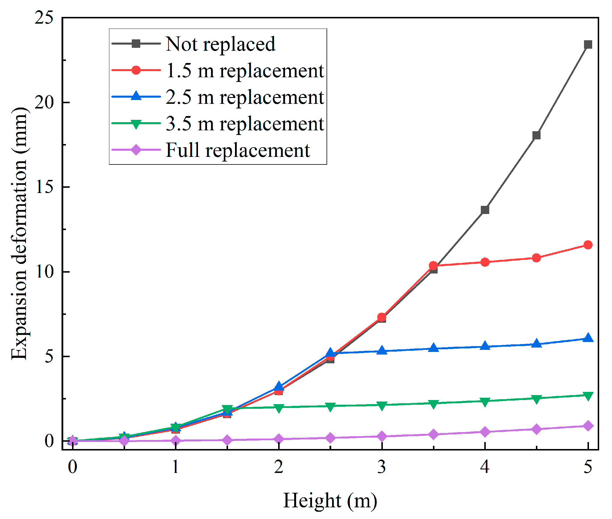
Figure 12 demonstrates that increasing the depth of fill material replacement significantly reduces subgrade expansion, with particularly pronounced effects on controlling deformation in the upper subgrade. At the subgrade surface, displacement decreased progressively from 23.42 mm (unreplaced) to 11.59 mm (1.5 m replacement), 6.06 mm (2.5 m replacement), 2.72 mm (3.5 m replacement), and 0.90 mm (full replacement). This substantial reduction clearly evidences the effectiveness of the replacement measure. Notably, in the shallow layer (e.g., the 1.5–2.5 m depth range), displacement in some replacement scenarios (1.5 m and 2.5 m) was slightly greater than in the unreplaced condition. This may be attributed to displacement altering the stiffness distribution and internal stress transfer pathways within the subgrade structure, resulting in a redistribution of local deformation. However, this effect does not undermine the overall trend of reduced surface deformation. The slightly higher displacement predicted in some intermediate layers is considered to reflect local deformation redistribution caused by the stiffness contrast between the replaced and unreplaced zones. Since the magnitude of this difference is small, it may also be partially influenced by numerical discretization and the assumption of uniform expansion. Therefore, it does not contradict the overall mitigation trend observed at the subgrade surface.
The mechanism underlying this phenomenon is intrinsically linked to the chemical properties of the uplift. As discussed in Section 4.1, the uplift is primarily driven by the oxidation of pyrite within the black shale fill material and the associated acidification effect. The primary function of replacement treatment is to physically isolate the deep-seated black shale fill from moisture and oxygen by substituting the original expansive fill at various depths with fill materials. The greater the replacement depth, the smaller the volume of black shale fill available for expansion reactions, thereby reducing the amount of material capable of generating expansion at its source. Additionally, the thicker layer of fill material acts as a form of ballast, partially constraining the deformation of the remaining expansive fill material beneath it.
From an engineering practice perspective, the data from this study provide direct evidence for determining an economically viable replacement depth. For example, increasing the replacement depth from 2.5 m to 3.5 m significantly reduced the top surface displacement from 6.06 mm to 2.72 mm, demonstrating a pronounced suppression effect. However, further increasing the depth to 5 m only reduced the displacement from 2.72 mm to 0.90 mm, indicating diminishing marginal returns. Consequently, remediation schemes need not pursue complete replacement. Instead, the minimum effective depth that stably controls deformation within permissible limits should be selected based on deformation control criteria and cost analysis. The quantitative results in Table 4 provide crucial support for this decision-making process.

4.3. Simplified Analytical Expressions for Uplift Prediction

The numerical results were further analyzed using a simplified analytical approach based on the expansion test data presented in Section 3.1.2. This approach is not intended to replace the numerical model but rather to provide simplified analytical expressions and practical engineering prediction formulas.
In the expansion test, the swelling ratio is expressed as:
  δ = h H s
where δ is the swelling ratio, Δh is the vertical expansion of the specimen, and Hs is the initial specimen height. In this study, chemically induced expansion was modeled numerically as an equivalent thermal expansion strain.
Therefore, the swelling ratio can be approximately related to the equivalent expansion coefficient by:
δ = η α e q T e q
And the equivalent expansion coefficient can be expressed as:
η = δ α e q T e q
where αeq is the equivalent expansion coefficient, ΔTeq is the equivalent temperature increment, η is the adjustment coefficient introduced to account for the amplification effect not directly represented by the equivalent temperature term.
It should be noted that the equivalent temperature increment does not represent an actual temperature change. It is a numerical parameter introduced to convert chemically induced expansion into an equivalent thermal strain. Therefore, its magnitude is not physically meaningful as a temperature but only reflects the strain level observed in the expansion tests.
According to the expansion test results, the swelling ratios under natural and oxidizing conditions were 4.41% and 6.87%. By applying a unified equivalent temperature increment of ΔTeq = 50, the calculated adjustment coefficient is 55. These values closely match those obtained from the numerical back-analysis. This agreement indicates that the expansion test results provide a reliable basis for estimating the equivalent expansion coefficient.
For the subgrade model, the free expansion of the expansive layer can be expressed as Uf = δH, where H is the thickness of the expansive layer. However, in the actual subgrade, the uplift is restrained by lateral constraints, the fixed bottom boundary, and the structural geometry. Therefore, a correction coefficient λ is introduced, and the surface uplift can be written as:
U = λ δ H
By combining Equation (10), the uplift can also be expressed as:
U = λ α e q T e q H
where U is the surface uplift of the subgrade, Uf is the free expansion displacement of the expansive layer, and λ is the correction coefficient reflecting the boundary constraint and structural restraint effects of the subgrade.
Using the natural-condition results in this study, with H = 5 m, δ = 4.41%, and U = 23.42, the correction coefficient is approximately λ = 0.106. Therefore, the simplified engineering prediction formula can be expressed as:
U = 0.106 δ H
Or equivalently,
U = 5.83 α e q T e q H
Under natural and oxidizing conditions, the predicted uplift values are 23.37 mm and 36.44 mm, respectively. These values closely match the numerical results of 23.42 mm and 36.59 mm. The above equations can provide a practical tool for rapid engineering estimation of subgrade uplift under different working conditions. Furthermore, the value of λ should be related to the time parameter. In future research, expansion data collected at different times can be incorporated into the model to derive a more accurate expression for λ, enabling better predictions of long-term roadbed expansion.
The replacement depth is denoted by d, the remaining expansive thickness can be expressed as Hd. A first-order estimation of the uplift can then be written as:
U ( d ) = λ α e q T e q ( H d )
This expression reflects the direct reduction in expansive thickness following replacement. However, it does not fully account for the stiffness redistribution and the additional constraint effects introduced by the replacement layer. To improve the prediction, a thickness-ratio attenuation term is introduced. Consequently, the uplift under replacement conditions can be expressed as:
U ( d ) = U 0 ( H d H ) m
where U0 is the uplift without replacement, and m is an attenuation exponent. Considering the small residual displacement under full replacement, the final form is expressed as:
U ( d ) = U r + ( U 0 U r ) ( H d H ) m
where Ur is the residual uplift under full replacement. Based on the numerical results in Table 4, U0 = 23.42 mm, Ur = 0.90 mm, and m ≈ 2.1. Therefore, the engineering prediction formula for the present case can be expressed as:
U ( d ) = 0.90 + 22.52 ( 5 d 5 ) 2.1
This equation is applicable for preliminary engineering predictions of uplift at different replacement depths.

4.4. The Necessity of Environmental Chemical Field Monitoring

The results from both laboratory water chemistry experiments and numerical simulations in this study collectively indicate that the uplift of subgrades in areas with black shale fill is a physical deformation process primarily governed by changes in the chemical environment. The oxidation rate of pyrite is strongly influenced by its chemical surroundings, particularly the migration and concentration distribution of moisture, oxygen, and reaction products such as Fe3+. Consequently, conventional methods that monitor only subgrade displacement, moisture content, or temperature are inadequate. To achieve early warning and precise prevention and control of uplift defects, monitoring of the environmental chemical field must be prioritized. It is recommended to deploy in situ monitoring systems along defect-prone sections, regularly collecting pore water samples or installing online sensors. Key monitoring indicators should include pore water pH, Eh (oxidation–reduction potential), and specific ion concentrations (e.g., Fe2+/Fe3+ ratio, SO42− concentration). By establishing correlations between chemical field parameters (such as sudden pH drops or sharp increases in SO42− concentration) and subsequent macroscopic deformation, expansion trends can be predicted earlier. This approach facilitates a shift from reactive remediation to proactive intervention, providing a scientific basis for railway safety operations and precision maintenance.
Moreover, the findings of this study suggest a pathway for developing targeted chemical remediation techniques. Since the root cause of the pathology is pyrite oxidation and the resulting acidification, in situ chemical modification methods may be considered. Examples include the injection of slow-release alkaline agents, such as magnesium oxide or calcium hydroxide suspensions. These methods can help neutralize the acidic environment and inhibit the oxidation chain reaction. As a result, the fill material may be chemically stabilized. Future research should incorporate long-term chemical field monitoring data to thoroughly evaluate the sustained efficacy of various chemical remediation approaches, their ecological impact on surrounding environments, and their economic feasibility. This will establish a comprehensive technical framework encompassing both ‘monitoring and early warning’ and chemical remediation.
Although the current approach offers a practical foundation for interpreting the uplift mechanism of black shale fill and assessing the engineering response under various replacement conditions, several aspects require further investigation. Notably, scale effects persist between laboratory testing and field conditions, as both the hydrochemical experiments and swelling tests were conducted on finely ground particles. Additionally, numerical studies that explicitly incorporate the complete chemical reaction process remain limited, and corresponding investigations integrating numerical modeling with laboratory experimental constraints are still insufficient. Consequently, the present numerical analysis only considers the effects of equivalent thermal expansion and gravity. While this approach cannot fully replicate the complete chemical–mechanical evolution of black shale fill, it provides a practical framework for linking laboratory-observed expansion behavior with field-scale uplift deformation. Future research should therefore combine in situ chemical monitoring, laboratory testing, and more advanced coupled constitutive models to enhance the reliability of long-term uplift predictions.

5. Conclusions

This study investigated the long-term uplift behavior of a black shale fill subgrade in the K166 section of the Zhangjiajie-Huaihua Railway through field monitoring, laboratory testing, and numerical simulation. The main conclusions are as follows:
(1)
Field monitoring demonstrated that subgrade uplift developed continuously during operation, with no clear trend of convergence observed throughout the monitoring period. This confirms that the deformation is a long-term, progressive process rather than a short-term, construction-induced disturbance.
(2)
Laboratory analyses of mineralogy, expansion, and water chemistry consistently indicate that pyrite oxidation is the primary process driving subgrade uplift. Under oxidizing conditions, pyrite oxidation creates an acidic environment that promotes the dissolution of carbonate and silicate minerals, along with the formation of secondary sulfate-bearing expansive products. These processes collectively result in significant swelling of the black shale fill.
(3)
The numerical results demonstrate that increasing the replacement depth of black shale fill effectively reduces uplift deformation and enables a quantitative evaluation of the relationship between replacement depth and uplift mitigation. Although slight local non-monotonic variations may occur at some intermediate depths due to stiffness redistribution and model simplifications, the overall mitigation trend is clear. This indicates that partial replacement can achieve substantial deformation reduction without the need for full replacement.
(4)
A simplified analytical framework is proposed to predict subgrade uplift using laboratory-derived expansion parameters. The resulting expressions allow for rapid estimation of uplift under various working conditions and replacement depths, offering a practical tool for engineering design and remediation assessment.
Overall, this study bridges the gap between chemical processes, laboratory observations, and engineering-scale deformation, offering a practical methodology for predicting and mitigating uplift in subgrades constructed with chemically reactive materials.

Author Contributions

Conceptualization, H.S.; methodology, M.Z. and W.L.; software, M.Z.; validation, X.L.; formal analysis, Y.W.; investigation, Y.W. and W.L.; resources, H.S.; data curation, H.S.; writing—original draft preparation, H.S. and M.Z.; writing—review and editing, Y.W.; supervision, X.L.; project administration, W.L. and X.L.; funding acquisition, X.L. All authors have read and agreed to the published version of the manuscript.

Funding

The research presented here is supported by the Natural Science Foundation of Sichuan Province for Young Scholars (2022NSFSC1117) and the Innovative Practice Bases of Geological Engineering and Surveying Engineering of Southwest Jiaotong University (YJG-2022-JD04).

Institutional Review Board Statement

Not applicable.

Informed Consent Statement

Not applicable.

Data Availability Statement

The original contributions presented in this study are included in the article. Further inquiries can be directed to the corresponding author.

Conflicts of Interest

Authors Honglin Sun, Yinghe Wang and Wei Li were employed by the company China Railway Siyuan Survey and Design Group Co., Ltd. The remaining authors declare that the research was conducted in the absence of any commercial or financial relationships that could be construed as a potential conflict of interest.

References

  1. Xiao, Y.; Chang, Z.; Mao, J.; Zhou, S.; Wang, X.; Wang, W.; Cai, D.; Zhu, H.; Long, Y. Evaluating the Effect of Rail Fastener Failure on Dynamic Responses of Train-Ballasted Track-Subgrade Coupling System for Smart Track Condition Assessment. Materials 2022, 15, 2675. [Google Scholar] [CrossRef]
  2. Murray, C.A.; Take, W.A.; Hoult, N.A. Measurement of vertical and longitudinal rail displacements using digital image correlation. Can. Geotech. J. 2015, 52, 141–155. [Google Scholar] [CrossRef]
  3. Mackie, S.L.; Koduri, G.; Hill, C.L.; Wakefield, R.J.; Hutchings, R.; Loy, C.; Dasgupta, B.; Wyatt, J.C. Dynamic response of ballasted High-Speed Railways: Insights from experimental measurements and 3D nonlinear numerical modelling. Transp. Geotech. 2025, 52, 101549. [Google Scholar] [CrossRef]
  4. Su, Y.; Cai, G.; Yin, F.; Shan, Y.; Wang, H. Investigation of the creep behavior and time-dependent constitutive model of red-stratum mudstone fill material in high-fill subgrade. Constr. Build. Mater. 2025, 458, 139560. [Google Scholar] [CrossRef]
  5. Zhang, C.; Jiang, G.; Buzzi, O.; Su, L. Full-scale model testing on the dynamic behavior of weathered red mudstone subgrade under railway cyclic loading. Soils Found. 2019, 59, 296–315. [Google Scholar] [CrossRef]
  6. Zhang, W.; He, Z.; Liu, Z.; Liu, Y. Study on dynamic resilience modulus and its prediction model of carbonaceous mudstone coarse-grained soil. Water Resour. Hydropower Eng. 2023, 54, 161–169. [Google Scholar] [CrossRef]
  7. He, Z.; Zhang, J.; Zhang, Y.; Zhang, L.; Yang, T. Compaction quality control of soil-rock filled subgrades in mountainous areas. Bull. Eng. Geol. Environ. 2025, 84, 326. [Google Scholar] [CrossRef]
  8. Chen, J.; Huang, B.; Shu, X.; Hu, C. DEM Simulation of Laboratory Compaction of Asphalt Mixtures Using an Open-Source Code. J. Mater. Civ. Eng. 2015, 27, 04014130. [Google Scholar] [CrossRef]
  9. Hu, M.; Huang, Z.; Chen, J.; Guo, Y.; Zhou, Y.; Liu, D.; Guo, R. Performance Study of Black Shale Modified Soil for Road Use Based on Eshelby-Mori-Tanaka Theory. Appl. Sci. 2024, 14, 1636. [Google Scholar] [CrossRef]
  10. Zhu, S.; Luo, J.; Wang, M.; Cai, C. Mechanical characteristic variation of ballastless track in highspeed railway: Effect of train–track interaction and environment loads. Railw. Eng. Sci. 2020, 28, 408–423. [Google Scholar] [CrossRef]
  11. Wang, L.-L.; Lei, X.; Liu, S. Investigation of immersion influence on dynamic properties of high-speed railway subgrade with semi-rigid waterproof functional layer through field-excitation testing. Can. Geotech. J. 2018, 55, 19–33. [Google Scholar] [CrossRef]
  12. Wang, P.; Ye, Y.; Zhang, Q.; Liu, J.; Yao, J. Investigation on the sulfate attack-induced heave of a ballastless track railway subgrade. Transp. Geotech. 2020, 23, 100316. [Google Scholar] [CrossRef]
  13. Wang, R.; Cheng, J.-J.; Gao, L.; Li, Z.-G.; Qi, Y.-L.; Wang, M.-T.; Ding, B.-S. Research on the swelling mechanism of high-speed railway subgrade and the induced railway heave of ballastless tracks. Transp. Geotech. 2021, 27, 100470. [Google Scholar] [CrossRef]
  14. Chen, J.; Li, A.; Bao, C.; Dai, Y.; Liu, M.; Lin, Z.; Niu, F.; Zhou, T. A deep learning forecasting method for frost heave deformation of high-speed railway subgrade. Cold Reg. Sci. Technol. 2021, 185, 103265. [Google Scholar] [CrossRef]
  15. Lin, Z.; Niu, F.; Li, X.; Li, A.; Liu, M.; Luo, J.; Shao, Z. Characteristics and controlling factors of frost heave in high-speed railway subgrade, Northwest China. Cold Reg. Sci. Technol. 2018, 53, 33–44. [Google Scholar] [CrossRef]
  16. Lyu, Q.; Long, X.; Ranjith, P.G.; Tan, J.; Kang, Y. Experimental investigation on the mechanical behaviors of a low-clay shale under water-based fluids. Eng. Geol. 2018, 233, 124–138. [Google Scholar] [CrossRef]
  17. Dai, Z.; Guo, J.; Yu, F.; Zhou, Z.; Li, J.; Chen, S. Long-term uplift of high-speed railway subgrade caused by swelling effect of red-bed mudstone: Case study in Southwest China. Bull. Eng. Geol. Environ. 2021, 80, 4855–4869. [Google Scholar] [CrossRef]
  18. Liu, C.-D.; Cheng, Y.; Jiao, Y.-Y.; Zhang, G.-H.; Zhang, W.-S.; Ou, G.-Z.; Tan, F. Experimental study on the effect of water on mechanical properties of swelling mudstone. Eng. Geol. 2021, 295, 106448. [Google Scholar] [CrossRef]
  19. Mohn, D.; Cutright, T.J.; Senko, J.; Abbas, A. Assessment of Sulfate Concentrations in Water Used During Chemical Stabilization and Its Potential Impact on Sulfate Induced Heave. Geotech. Geol. Eng. 2016, 34, 285–296. [Google Scholar] [CrossRef]
  20. Jiang, L.; Niu, D. Study of deterioration of concrete exposed to different types of sulfate solutions under drying-wetting cycles. Constr. Build. Mater. 2016, 117, 88–98. [Google Scholar] [CrossRef]
  21. Talluri, N.; Congress, S.S.C.; Bheemasetti, T.V.; Puppala, A.J.; Yu, X. Assessment of Sulfate-Induced Heave in Chemically Treated Soils Using a Novel Hybrid Sensor. Geotech. Test. J. 2021, 44, 30–47. [Google Scholar] [CrossRef]
  22. Liu, Z.; Huang, K.; Dai, Z.; Yu, F.; Song, X.; You, Y.; Li, Z.; Chen, S. Multistage reaction characteristics and kinetic effects of temperature on pyrite oxidation in black rock layers: Insights from high-speed railway subgrade filling materials. Case Stud. Constr. Mater. 2025, 22, e04485. [Google Scholar] [CrossRef]
  23. Liu, Z.; Dai, Z.; Yu, F.; Cai, H.; Xu, Z.; Chen, S. Effects of hydrodynamic conditions and particle size on oxidation kinetics and swelling mechanisms of black rock subgrade in high-speed railways. Constr. Build. Mater. 2025, 494, 143380. [Google Scholar] [CrossRef]
  24. McCabe, B.A.; McKeon, É.P.; Virbukiene, R.J.; Mannion, P.J.; O’connell, A.M. Pyritiferous mudstone-siltstone: Expansion rate measurement and prediction. Q. J. Eng. Geol. Hydrogeol. 2015, 48, 41–54. [Google Scholar] [CrossRef]
  25. Wang, A.; Xu, Y.; Xu, Y. Numerical modeling on the deformation features of expansive soil slopes under moisture variations based on Fractal model. Comput. Geotech. 2024, 165, 105900. [Google Scholar] [CrossRef]
  26. Wu, X.; Vanapalli, S.K. Three-dimensional modeling of the mechanical behavior of a single pile in unsaturated expansive soils during infiltration. Comput. Geotech. 2022, 145, 104696. [Google Scholar] [CrossRef]
  27. Gao, L.; Du, P.; Zhou, W.; Xu, R.; Dong, J.; Wang, Y.; Yan, Z. Numerical simulation study on the effects and mechanisms of bedding plane mechanical parameters on hydraulic fracture propagation in shale. Water Resour. Hydropower Eng. 2025, 56, 36–250. [Google Scholar] [CrossRef]
  28. GB/T 50123-2019; Standard for Geotechnical Testing Method. China Planning Press: Beijing, China, 2019.
  29. Baker, B.J.; Tyson, G.W.; Goosherst, L.; Banfield, J.F. Insights into the diversity of eukaryotes in acid mine drainage biofilm communities. Appl. Environ. Microbiol. 2009, 75, 2192–2199. [Google Scholar] [CrossRef]
  30. TB 10001-2016; Code for Design of Railway Earth Structure. China Railway Publishing House: Beijing, China, 2016.
  31. Fu, D.; Cao, C.; Li, P.; Fan, J.; Sun, J. Comparison of the development of engineering geological investigation codes between water conservancy and railway, highway industries. Water Resour. Hydropower Eng. 2025, 56, 546–560. [Google Scholar] [CrossRef]
  32. Rybacki, E.; Herrmann, J.; Wirth, R.; Dresen, G. Creep of Posidonia Shale at Elevated Pressure and Temperature. Rock Mech. Rock Eng. 2017, 50, 3121–3140. [Google Scholar] [CrossRef]
  33. Kim, M. Investigation of Indirect Shear Strength of Black Shale for Urban Deep Excavation. Buildings 2024, 14, 3050. [Google Scholar] [CrossRef]
  34. Zhou, Z.; Zhang, F.; Fu, H.; Xiu, N.; Guan, B.; Cai, B. A thermal–mechanical coupled DEM model for deep shale reservoir: The effects of temperature and anisotropy. Rock Mech. Rock Eng. 2024, 57, 3707–3726. [Google Scholar] [CrossRef]
  35. Shu, X.-H.; Zhang, Q.; Lu, G.-N.; Yi, X.-Y.; Dang, Z. Pollution characteristics and assessment of sulfide tailings from the Dabaoshan Mine, China. Int. Biodeterior. Biodegrad. 2018, 128, 122–128. [Google Scholar] [CrossRef]
  36. Sun, C.; Ling, S.; Wu, X.; Li, X.; Chen, J.; Jiang, W. Oxidation of black shale and its deterioration mechanism in the slip zone of the Xujiaping landslide in Sichuan Province, Southwestern China. Catena 2021, 200, 105139. [Google Scholar] [CrossRef]
  37. Duan, G.; Xu, G.; Luo, W.; Li, S. Study on shear characteristics of mudstone soil-rock mixture under acid-alkali environment. Water Resour. Hydropower Eng. 2024, 55, 148–155. [Google Scholar] [CrossRef]
  38. Huang, J.; Li, Q.; Wu, P.; Wang, S.; Lu, W.; Fu, Y.; Gu, S.; Li, X. Impact of acid mine drainage into a small karst watershed in terms of enhancing erosion of carbonate rocks and significant kinetic carbon isotope fractionation in Southwest China. J. Hydrol. 2025, 660, 133479. [Google Scholar] [CrossRef]
  39. Zeng, X.; Han, Y.; Hu, L.; Shu, J.; Lin, F.; Luo, X.; Fan, X.; Wang, R.; Chen, M. Formation characteristics of CaSO4·2H2O passivation layer during rhodochrosite leaching by sulfuric acid: Mineralogy and molecule simulation perspectives. Chem. Eng. Sci. 2025, 301, 120701. [Google Scholar] [CrossRef]
  40. Huminicki, D.M.; Rimstidt, J.D. Neutralization of sulfuric acid solutions by calcite dissolution and the application to anoxic limestone drain design. Appl. Geochem. 2008, 23, 148–165. [Google Scholar] [CrossRef]
  41. Noe, D.C.; Higgins, J.D.; Olsen, H.W. Steeply Dipping Heaving Bedrock, Colorado: Part 3—Environmental Controls and Heaving Processes. Environ. Eng. Geosci. 2007, 13, 325–344. [Google Scholar] [CrossRef]
  42. Valdés, A.C.; De Souza, D.J.; Capraro, A.P.B.; Pieralisi, R.; Medeiros, M.H.F. On the relevance of pyrite oxidation: A thermodynamic and experimental evaluation of concrete degradation. Cem. Concr. Compos. 2025, 164, 106295. [Google Scholar] [CrossRef]
  43. Yan, H.; Zhao, X.; Wünnemann, B.; Jian, L.; Chen, M.; Xiao, D. A method for predicting the subgrade uplift intensity along a high? speed railway track in red-bed areas in China. Bull. Eng. Geol. Environ. 2023, 82, 303. [Google Scholar] [CrossRef]
  44. Zhong, Z.; Zhou, Q.; Lyu, L.; Wu, P.; Li, T.; Yang, B.; Fan, X. Time-dependent swell–shrink behavior of red-bed mudstone under cyclic wetting and drying. Bull. Eng. Geol. Environ. 2023, 82, 470. [Google Scholar] [CrossRef]
  45. Xie, Z.; Liao, X.; Tan, Y.; Ling, S.; Chen, J.; Wu, X. Insight into Subgrade Long-Term Uplift Characteristic of Swelling Red-Bed Controlled by Temperature and Cyclic Load: From Laboratory Experiments Open Access. Lithosphere 2025, 2025, lithosphere_2024_247. [Google Scholar] [CrossRef]
  46. Ghalamzan, F.; De Rosa, J.; Gajo, A.; Di Maio, C. Swelling and swelling pressure of a clayey soil: Experimental data, model simulations and effects on slope stability. Eng. Geol. 2022, 297, 106512. [Google Scholar] [CrossRef]
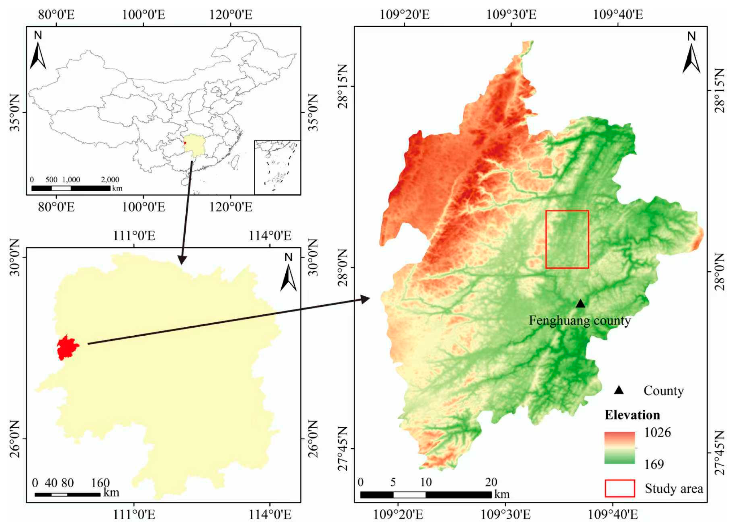
Figure 1. Geographic location map of the study area.
Applsci 16 04705 g001
Figure 2. The uplift of the subgrade and the depth of the black shale fill along the alignment, (a) monitoring curve of axial deformation for railway up line, (b) monitoring curve of axial deformation for railway down line.
Applsci 16 04705 g002
Figure 3. The uplift of the subgrade over time.
Applsci 16 04705 g003
Figure 4. Flowchart of the research procedure.
Applsci 16 04705 g004
Figure 5. Expansion tests under different operating conditions and internal diagrams of the instrument. (a) Distilled water condition; (b) 0.05 mol/L FeCl3 solution condition; (c) internal diagrams of the instrument.
Applsci 16 04705 g005
Figure 6. Variation in expansion strain with time.
Applsci 16 04705 g006
Figure 7. (a) Unit cell model; (b) subgrade model, d represents the depth of the replaced subgrade section.
Applsci 16 04705 g007
Figure 8. Unit cell model expansion displacement diagram: (a) natural condition; (b) oxidation condition.
Applsci 16 04705 g008
Figure 9. Subgrade model expansion displacement diagram: (a) natural condition; (b) oxidation condition.
Applsci 16 04705 g009
Figure 10. Expansion displacement diagrams of the roadbed models at different replacement depths: (a) Replacement 1.5 m; (b) Replacement 2.5 m; (c) Replacement 3.5 m; (d) Replacement 5 m.
Applsci 16 04705 g010
Figure 11. Diagram of the uplifting mechanism in black shale filler subgrades.
Applsci 16 04705 g011
Figure 12. Deformation curves of subgrade uplift at different replacement depths of black shale filler.
Applsci 16 04705 g012
Table 1. Filler mineral composition unit: wt. %.
MineralQuartzFeldsparCalciteDolomitePyriteGypsumIlliteChlorite
K166+440 301131151-75
K166+470 24941141155
K166+497 14955131143
K166+506 40.413.422.06.23.33.45.65.7
K166+52032926133278
Fresh shale49.021.87.434.92.1-5.62.4
Table 2. Water chemistry results unit: (mg/L).
SolutionSFe CaMgKSi
Distilled water18.270.015.091.042.160.24
0.05 mol/L FeCl3 solution547.003642.001159.70130.3082.904.58
Table 3. Relevant parameters.
MaterialsDensity
(kg·m−3)
Modulus of Elasticity
(MPa)
Poisson RatioConductivity
(W·m−1·K−1)
Heat
Capacity
(J·kg−1·K−1)
Coefficient of Expansion
(K−1)
Soil1800500.350.9511001.6 × 10−5
Filler1900700.31.058806.5 × 10−7
Table 4. Expansion displacement along the central axis of the subgrade at different replacement depths. Unit: mm.
Height (m)Replacement 0 mReplacement 1.5 mReplacement 2.5 mReplacement 3.5 mReplacement 5 m
000000
0.50.18320.17920.21950.25560.0069
10.68870.69230.78430.84250.0266
1.51.60731.63321.70711.93190.0626
22.96852.97033.20652.00190.1164
2.54.83115.00015.18732.07090.1893
37.24317.31925.31552.14150.2831
3.510.131610.35435.46502.23910.3999
413.655810.56555.57492.36880.5419
4.518.051710.81715.71982.52920.7101
523.421211.58796.06092.71810.9045
Disclaimer/Publisher’s Note: The statements, opinions and data contained in all publications are solely those of the individual author(s) and contributor(s) and not of MDPI and/or the editor(s). MDPI and/or the editor(s) disclaim responsibility for any injury to people or property resulting from any ideas, methods, instructions or products referred to in the content.