1. Introduction
Cable-stayed bridges are widely adopted worldwide due to their aesthetic appearance and excellent seismic performance [
1]. As a primary load-bearing component, a stay cable consists of multiple steel strands and is typically protected by a high-density polyethylene (HDPE) sheath to enhance durability and corrosion resistance [
2]. During cold seasons, ice accretion can readily form on the HDPE sheath. This accreted ice not only intensifies wind-induced vibrations of the stay cable but may also shed as large ice blocks, posing serious threats to traffic safety beneath the bridge [
3]. In recent years, ice-shedding incidents have been reported on multiple cable-stayed bridges worldwide, leading to traffic disruption and substantial economic losses [
4,
5]. Consequently, stay-cable icing has become a critical concern in bridge operation and maintenance.
Existing icing mitigation approaches can generally be categorized into anti-icing and de-icing [
6]. Anti-icing aims to suppress water adhesion through hydrophobic coatings [
7] or to prevent icing by embedding heating elements to provide thermal input [
8]. De-icing methods include manual removal [
9], chemical de-icing agents [
10], and various physical techniques such as mechanical scraping, thermal melting, ultrasonic vibration, and microwave delamination [
11,
12]. In practice, anti-icing solutions often incur high maintenance costs and are therefore unfavorable for long-term field applications; manual removal is inefficient and involves substantial safety risks, while chemical agents may damage bridge components. In contrast, mechanical de-icing offers lower cost, higher efficiency, and improved operational safety, and has been extensively applied in transmission-line de-icing scenarios that share certain similarities with stay-cable de-icing.
Despite these advances, dedicated studies on stay-cable de-icing remain limited, and existing efforts mainly fall into two streams: (i) climbing mechanisms for stay-cable inspection robots and (ii) ice removal technologies for transmission lines. The former targets autonomous climbing and inspection on large-diameter, steeply inclined cables, whereas the latter focuses on removing ice accretion from conductors.
Regarding stay-cable climbing mechanisms, a variety of designs have been developed to improve adhesion and stability on large-diameter and high-inclination cables. Xu et al. [
13] proposed a stay-cable climbing robot based on symmetric distribution, featuring an independent quadrilateral suspension and a “V”-shaped stabilizing structure [
14]; Sun et al. [
15] developed a self-traction, heavy-load inspection robot; Zheng et al. [
16] introduced a palm-inspired adhesive structure to enhance attachment on cylindrical cables; and Zhang et al. [
17] proposed a flying-type stay-cable climbing robot assisted by ducted fans. These studies have improved the mobility and attachment capability of stay-cable robots, establishing a foundation for autonomous operations; however, de-icing under icing conditions has rarely been addressed.
In transmission-line de-icing, mechanisms and device-level solutions have been extensively investigated, including motor-driven impact de-icing [
18,
19], rotary-tool milling de-icing [
20], vibration-based de-icing [
21], and ultrasonic de-icing [
22]. Meanwhile, theoretical and numerical studies have clarified key mechanisms: Ji et al. [
23] analyzed the transient response of ice-conductor assemblies under impact loading, and Zhu et al. [
24] examined the influence of ice thermal properties on melting efficiency. These studies provide valuable references in both method design and mechanism understanding.
However, transmission lines and stay cables differ substantially in engineering characteristics: transmission lines usually have small diameters (typically <50 mm) and low inclinations (nearly horizontal), with relatively thin and morphologically simple ice accretion; by contrast, stay cables are much larger in diameter (approximately 80–200 mm) with a wide inclination range (30–90°), and the ice layer is thicker and more spatially complex [
25]. These features make friction-dependent tracked or wheeled climbing mechanisms prone to failure under icing conditions [
26,
27], thereby limiting the direct transferability of transmission-line de-icing solutions to stay-cable applications. Therefore, stay-cable de-icing must address multiple challenges, including stable climbing under high-inclination and low-friction icing conditions, as well as achieving efficient ice removal while ensuring operational safety. Under these constraints, the design of dedicated de-icing devices for stay cables and the systematic investigation of their de-icing behavior remain insufficiently explored.
To tackle this challenge, this study proposes a scheme integrating quadrotor aerodynamic assistance with thermo-mechanical coupled de-icing and develops a quadrotor-assisted stay-cable de-icing device. In this context, rotor-based power schemes have already been explored in inspection and de-icing applications [
28]. Compared with conventional cable-inspection robots and de-icing devices, the proposed scheme uses rotor-induced aerodynamic assistance to reduce the dependence on cable-surface friction, thereby improving its adaptability under low-friction iced stay-cable conditions. In addition, the device can first climb to the target position and then perform top-down de-icing, thereby making use of gravity to reduce operating energy consumption. Furthermore, a thermo-mechanical coupling milling-based de-icing design is adopted. This design improves de-icing effectiveness while retaining the relatively low-impact characteristic of milling de-icing and, together with the lightweight design of the device, effectively reduces its influence on the stay cable.
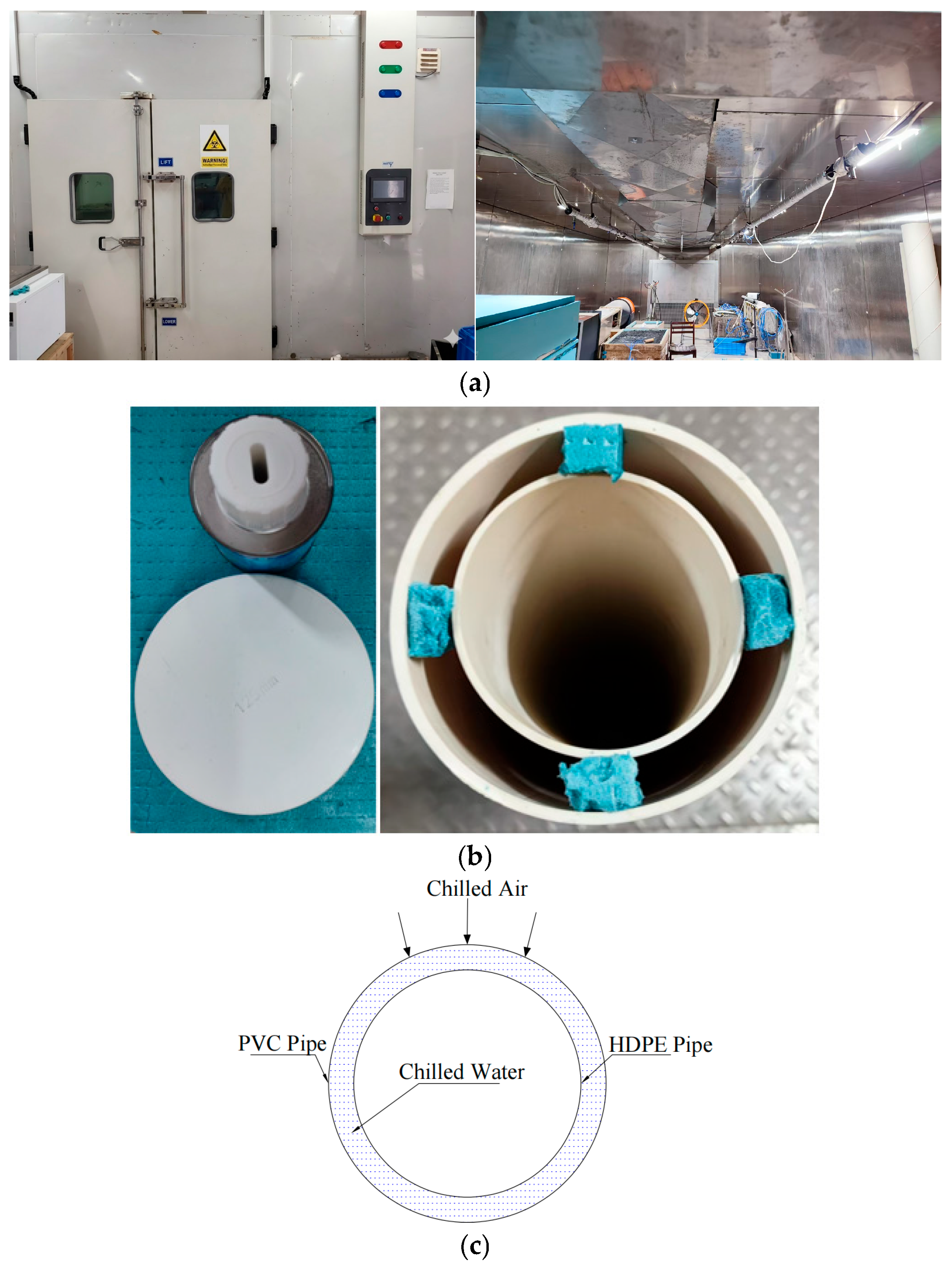
On this basis, the present study is carried out as follows. First, the integrated system is designed in SolidWorks (v2021). Second, indoor mechanical-only de-icing experiments and explicit dynamic simulations are performed to quantify the effects of normal clamping force and axial thrust and to validate the numerical model for parametric analysis. Third, temperature-rise tests are conducted to establish the power–temperature response of the embedded resistance wire, followed by thermo-mechanical de-icing tests to evaluate de-icing performance under reduced thrust. Finally, thermal-balance tests are carried out to assess temperature decay and its influence on de-icing efficiency during continuous operation. This stepwise workflow verifies the feasibility and engineering applicability of the proposed device.
2. System Design and De-Icing Mechanism
2.1. System Architecture and Structural Design
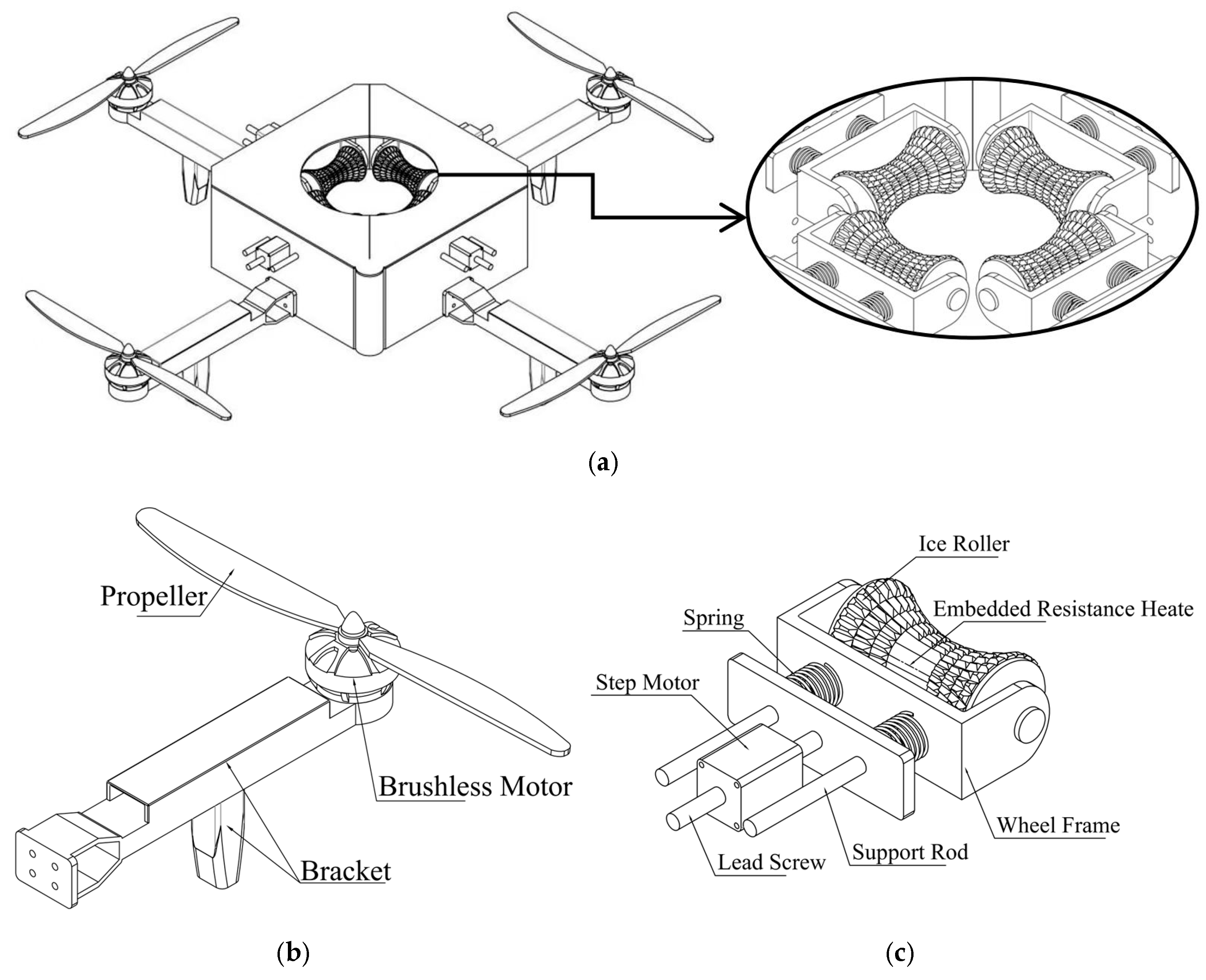
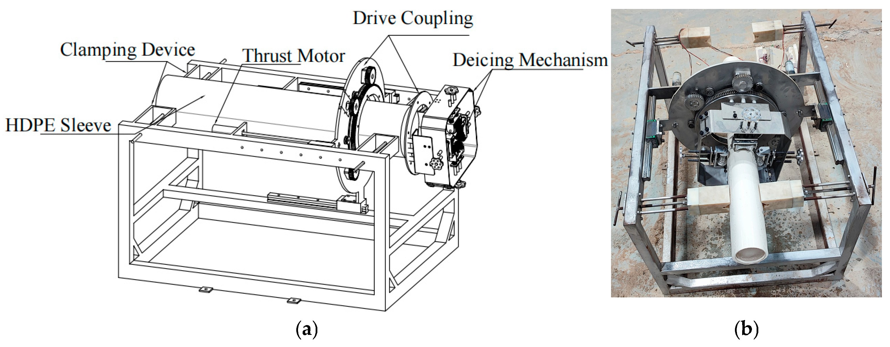
The prototype was designed for a stay cable with a diameter of 90 mm. The de-icing device employs a high-strength aluminum-alloy hinged split frame and consists of two subsystems: an aerodynamic assist unit and a de-icing unit (
Figure 1a). The aerodynamic assist unit is mounted to the frame via a support bracket to provide propulsion and attitude control. The de-icing unit is attached via a lead-screw assembly, enabling controlled radial infeed for ice cutting and peeling. In this study, a cable diameter of 90 mm was selected as a representative case for prototype design and laboratory validation. The proposed structural scheme has the potential to be adapted to different cable diameters by adjusting the structural dimensions and component selection of the key parts of the device.
2.1.1. Aerodynamic Assist Unit
The propulsion unit adopts a quadrotor mobility module design. The mobility module is bolted to the hinged split frame via a support bracket; the brushless motor is an X4110S multirotor motor, paired with an APC1238 propeller (
Figure 1b). This combination provides approximately 100 N of thrust under rated conditions, while the estimated total weight of the device with all modules installed is about 4.5 kg, which is far less than the thrust provided by the rotors.
Unlike conventional climbing mechanisms, the quadrotor mobility module does not rely on friction generated by the contact between the device’s clamping mechanism and the ice as the basis for movement. This scheme directly solves the climbing stability problem of stay cables under large-inclination and low-friction conditions at the design level, and creates the conditions for top-down de-icing by the de-icing unit. Consequently, the device’s own weight is converted into an assistive force during de-icing, thereby improving energy efficiency.
Because the quadrotor mobility module’s effectiveness is already evident from its design and component selection, and because the present study prioritizes the de-icing performance of the thermo-mechanical unit, the quadrotor module was not experimentally validated indoors—an omission that also prevents aerodynamic disturbances in the de-icing tests.
2.1.2. De-Icing Unit
The de-icing unit consists of an arc-shaped milling de-icing wheel, a lead-screw–spring force-regulation module, and an embedded heating module (
Figure 1c). It is rigidly connected to the open-close frame via the lead-screw thread and enables radial infeed. The wheel is designed with a circular arc profile according to the cable diameter, so as to maintain stable contact with the iced outer surface and distribute the contact load more uniformly. The force-regulation module provides the normal clamping force, achieved by compressing a spring through lead-screw displacement. With the assistance of the axial thrust, the wheel can perform continuous cutting and peeling. The heating module embeds a resistance wire into the axial groove of the wheel, delivering directional heating near the wheel surface to weaken ice strength and reduce interface adhesion.
2.2. Working Principle of Thermo-Mechanical De-Icing
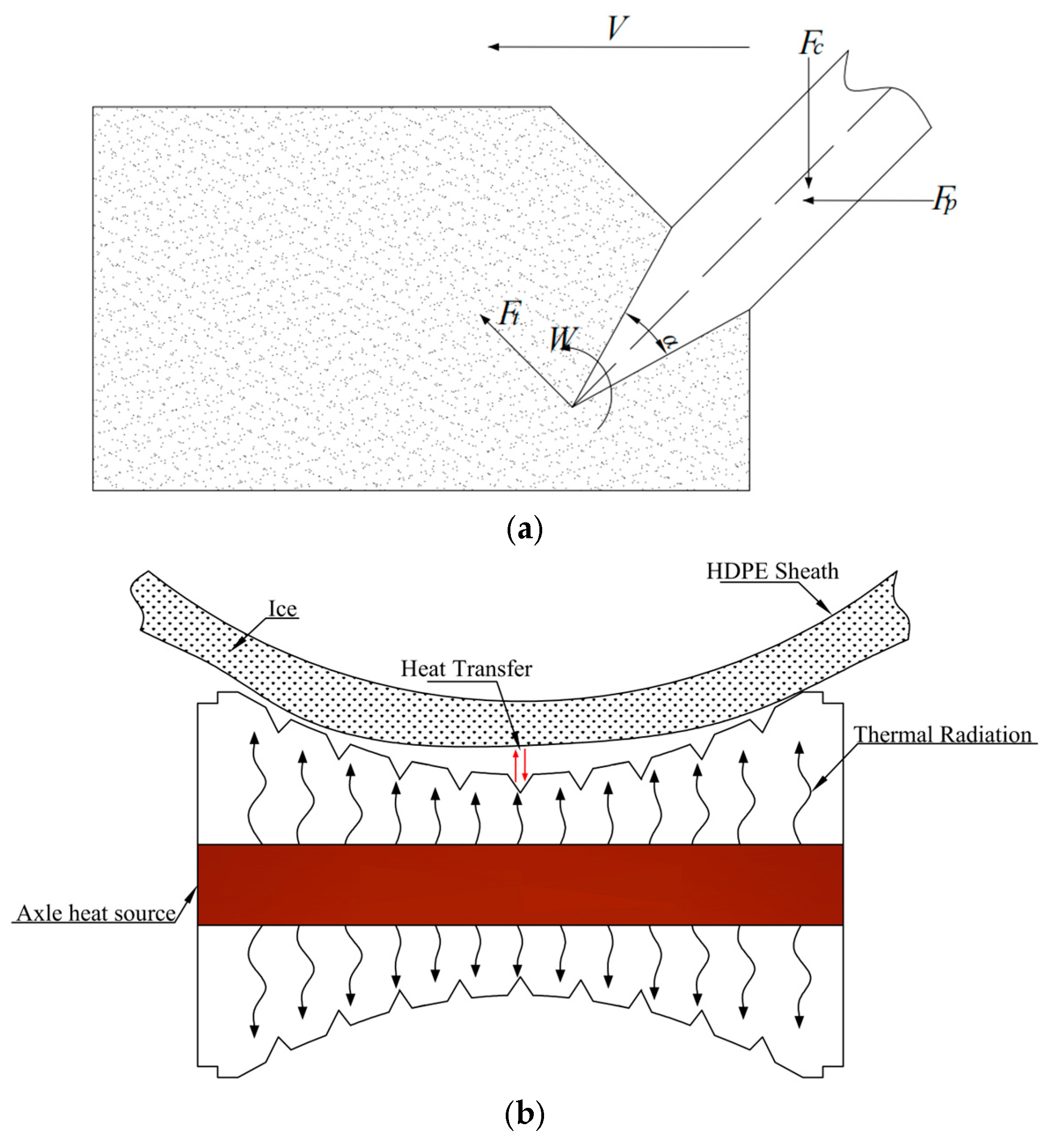
When the device operates along the stay cable, the de-icing wheel breaks the ice layer through a coupled normal–tangential cyclic contact process (
Figure 2a). The force conditions involved in mechanical de-icing can be divided into the following stages.
Stage I: Normal-load-induced failure (clamping force Fc).
Before de-icing starts, the spring is compressed by the lead screw to generate a normal clamping force
Fc. When the cutting edge indents into the ice under
Fc, stress concentration occurs. The maximum principal stress satisfies Equation (1).
In Equation (1), denotes the maximum principal stress; is the number of effective cutting blades; and is the effective contact area between a single blade and the ice. Brittle failure is initiated when reaches or exceeds the local yield strength of ice.
Stage II: Thrust-driven shear failure (axial thrust Fp).
After the de-icing wheel is pressed against the ice layer, the drive unit applies an axial thrust
Fp to translate the wheel along the stay-cable direction. After overcoming friction,
Fp is converted into an effective shear action on the ice, expressed as Equation (2):
In Equation (2), denotes the shear stress acting on the ice induced by the de-icing wheel; is the applied axial thrust; is the kinetic friction coefficient between the blade and the ice; is the cutting width of a single blade; and is the penetration depth of a single blade into the ice. Shear failure is initiated when τ reaches or exceeds the shear-yield (or shear-strength) threshold of ice, where stress concentration promotes intercrystalline sliding and local shear rupture.
Stage III: Cyclic crushing and impact due to passive rotation.
During de-icing under
Fp, the blades undergo passive rotation driven by the wheel translation. This produces repeated indentation-shear cycles as described above, together with impact torque and impact stress generated by blade rotation, as given by Equations (3) and (4):
In Equations (3) and (4), is the impact torque; is the effective radius (moment arm) of the cutter head; is the impact stress; is the effective mass of a single blade; is the rotational speed of the blade; is the impact contact duration; and is the impact contact area.
The above mechanical analysis indicates that de-icing performance is primarily governed by the axial thrust Fp and the normal clamping force Fc acting on the de-icing wheel.
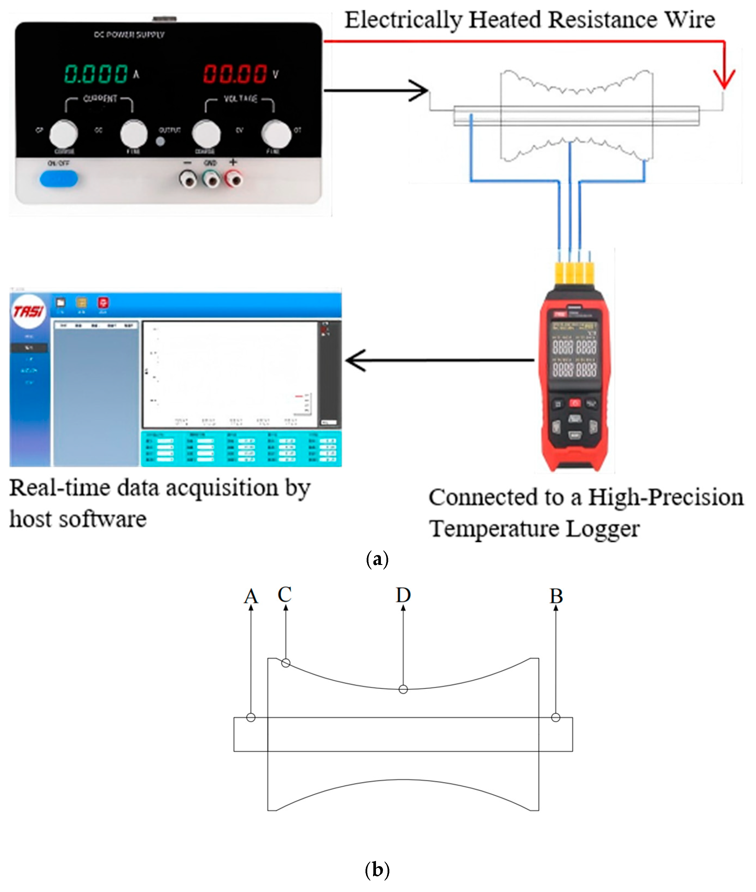
Although purely mechanical milling can remove ice, it may suffer from an insufficient ice removal ratio and constraints on allowable mechanical loads. Therefore, this study introduces a thermal-assistance scheme: a resistance-wire heating module is integrated into the axial groove of the wheel shaft. Joule heating raises the wheel temperature, and the supplied heat weakens the ice microstructure and reduces the cutting resistance (
Figure 2b). This design follows the thermo-mechanical coupling mechanism discussed by Song et al. [
29], in which thermal energy facilitates ice-layer delamination by a thermal-softening effect. The heating power is determined by the electrical relation
.
Because the resistance wire is wound inside the shaft groove, the resistance wire and the shaft are treated as an integrated body. Neglecting convective heat exchange between the wheel and ambient air, the internal heat-conduction model of the wheel is described by Equations (5) and (6):
In Equations (5) and (6), is the temperature at radial position r (°C); is the wheel-shaft temperature (°C); is the total heating power of the resistance wire (W); is the equivalent thermal conductivity of the wheel W/(M·K); is the shaft length (m); is the radial distance from the axis to a point in the wheel (m); and is the maximum wheel radius (m). These equations describe the radial temperature field induced by uniform heating; the closer to the shaft, the higher the temperature.
Once the wheel surface reaches the target temperature, it contacts the ice layer and heat conduction begins. Based on Fourier heat-conduction theory, the instantaneous wheel–ice heat-transfer process can be expressed by Equation (7). Meanwhile, the strength degradation of ice caused by heat diffusion in the ice layer can be described by Equation (8):
In Equations (7) and (8), is the heat-flux density at the wheel–ice interface; is the thermal conductivity of ice; is the temperature gradient between the wheel and the ice; is the thermal diffusivity of ice; is the wheel–ice contact time during de-icing; denotes the compressive/shear strength of ice at temperature ; denotes the compressive/shear strength at the reference temperature ; is the temperature-dependent decay coefficient; is the current ice temperature; and is the reference temperature.
4. Results
4.1. De-Icing Phenomena and Evaluation Metrics
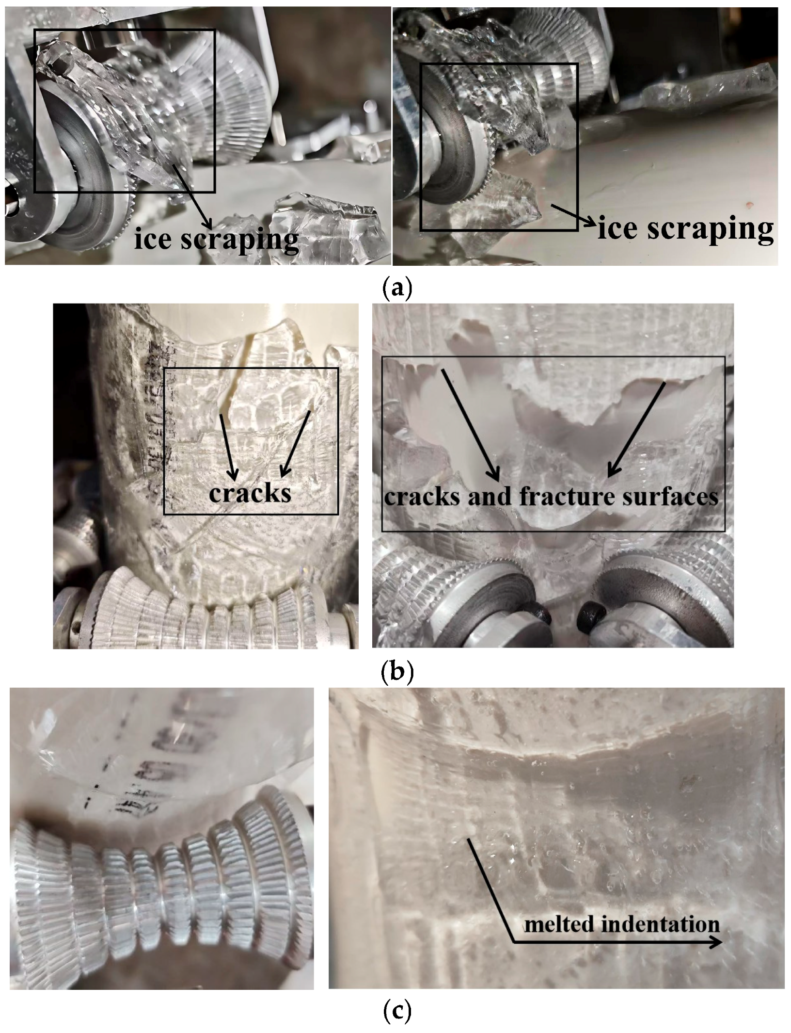
During cutter-wheel de-icing, ice failure is initiated by local stress concentration within the wheel–ice contact zone. As illustrated in
Figure 6a, the cutter wheel first contacts the ice layer under the normal clamping force, inducing localized stress concentration and subsequent yielding/failure of the ice. The axial thrust then drives the wheel forward, scraping the failed ice off the sheath surface and completing the removal process.
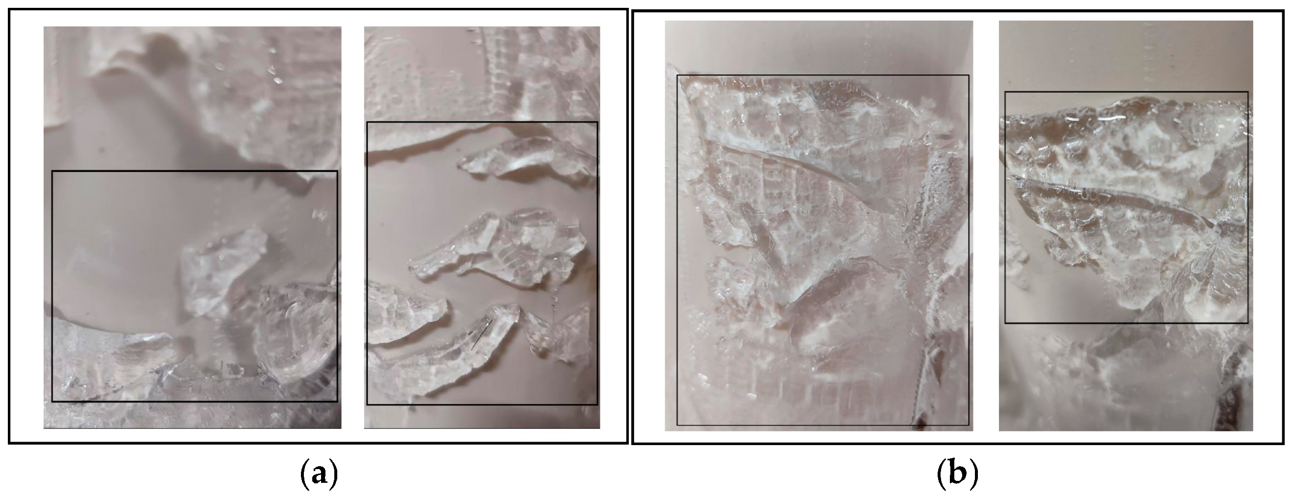
Depending on the actuation mode, two failure patterns are observed. Under purely mechanical de-icing, failure is characterized by brittle fracture accompanied by localized ductile deformation. When the cutter wheel contacts the ice under normal clamping, the local stress rapidly exceeds the yield strength and fracture toughness of ice; cracks initiate at the contact edge and propagate along the ice surface (
Figure 6b). As cracks coalesce laterally, a clear fracture surface forms and interfacial delamination occurs, resulting in a “compression-induced fracture” pattern. Under thermo-mechanical de-icing, the dominant pattern shifts to temperature-assisted yielding governed by thermal softening and local phase change. As the wheel temperature increases, heat exchange occurs in the contact zone; the ice undergoes solid–liquid phase transition during compression, with fine water droplets observed on the surface and distinct indentation marks left by the wheel (
Figure 6c), indicating a “compression-induced melting/softening” pattern.
Although the same mode follows a consistent failure pattern, different parameters lead to notably different damage severity and final removal outcomes. Due to non-uniform stress distribution, part of the ice may remain on the sheath surface after de-icing as residual ice. To systematically evaluate de-icing performance, this study adopts an evaluation scheme using the ice removal ratio as the primary metric, supplemented by the residual-ice size distribution. The ice removal ratio is defined as:
In Equation (9), is the initial ice-covered area, and is the residual-ice area after the de-icing operation. is taken as the lateral area of the iced segment of the sheath, calculated as , where is the outer radius of the sheath and is the length of the evaluated ice-covered segment. is the sum of the areas of all residual ice patches. The area of each individual ice patch is estimated by approximating its contour as an equivalent quadrilateral. Based on the equivalent area , residual ice is classified as small-sized ( < 100 mm2), medium-sized (100 mm2 ≤ < 900 mm2), or large-sized ( ≥ 900 mm2).
4.2. Mechanical De-Icing Results
4.2.1. Laboratory Test Results
A baseline condition of Fc = 35 N and Fp = 150 N was used to compare indoor experiments with simulations, in order to verify the validity of the numerical model for subsequent parametric extension.
Laboratory de-icing experiments showed that, under the 5 mm ice-thickness condition, the de-icing wheel formed a stable failure path, enabling continuous ice removal from the de-icing zone. Three repeated experiments yielded ice removal ratios of 77.6%, 78.1%, and 78.5%, with a mean of 78.1% (rounded to 78%) and an error range of approximately ±0.5%. As shown in
Figure 7a, the residual ice was mainly distributed near the incompletely removed edge regions and was dominated by medium-sized fragments.
When the ice thickness increased to 10 mm, the continuity of the de-icing process decreased, and both the amount and size of the residual ice increased. The corresponding ice removal ratios were 61.3%, 62.7%, and 61.8%, with a mean of approximately 62% and an error range of about ±0.7%, indicating reduced de-icing effectiveness under the thicker-ice condition. As shown in
Figure 7b, the residual ice was mainly block-like, and the area of large residual ice exceeded that of small- and medium-sized residual ice. This is attributed to stress attenuation within the thicker ice layer, which prevented the fracture zone from penetrating the full thickness and led to residual ice remaining mainly in the middle and lower regions.
4.2.2. Numerical Simulation Results
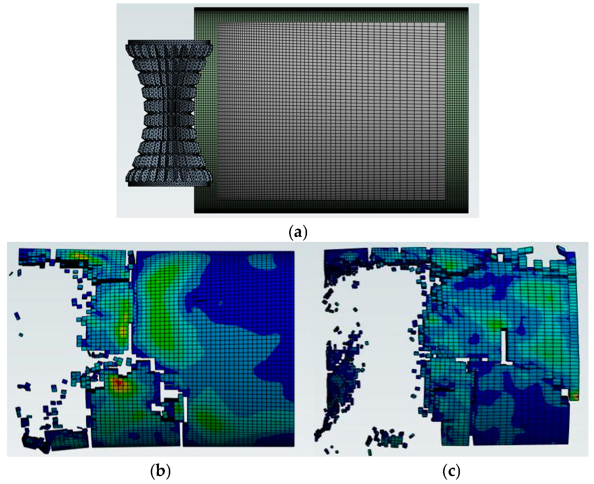
As shown in
Figure 8, the simulated ice removal ratios under the 5 mm and 10 mm ice-thickness conditions were 81% and 67%, respectively, consistent with the experimental trend, with a difference of approximately 4 percentage points. This discrepancy mainly results from statistical deviation in the equivalent-area estimation of residual-ice contours and the idealized treatment of material parameters and contact conditions in the simulation. Considering the error range of the repeated experiments, the difference is acceptable overall. In addition, the simulation reproduced the main fracture characteristics observed in the experiments, namely fine and scattered residual ice at 5 mm and larger block-like adhered residual ice at 10 mm. These results indicate that the numerical model can reasonably capture both the ice removal performance and the fracture behavior, and can therefore be used to extend the operating conditions beyond those covered in the laboratory experiments.
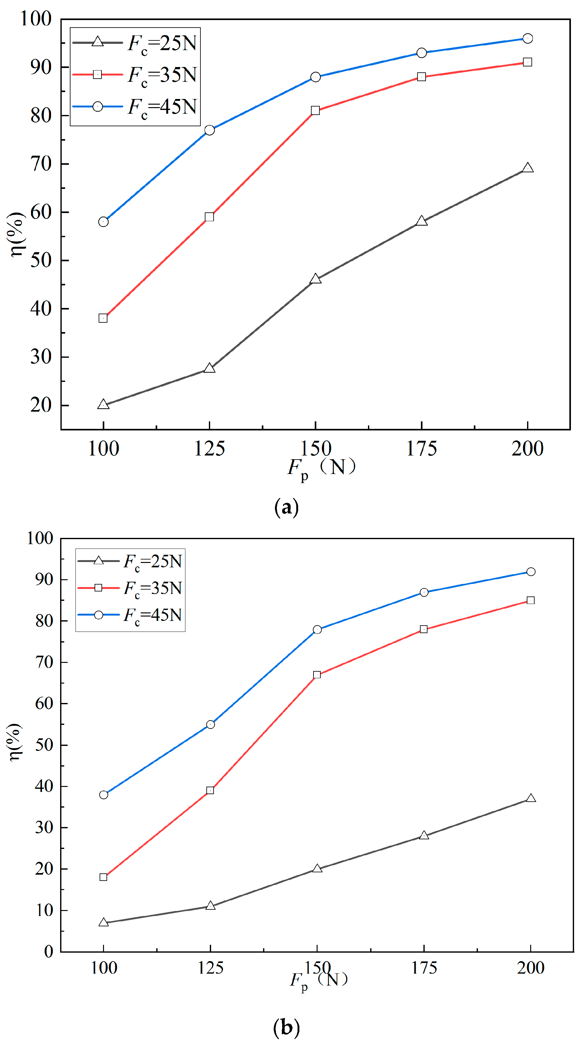
Based on the validated simulation, the ice removal ratios under different conditions are summarized in
Figure 9. Under the same
Fc and
Fp, the overall ice removal ratio for 5 mm ice is consistently higher than that for 10 mm ice, directly reflecting the strong influence of ice thickness on removal efficiency.
From the perspective of axial thrust, both thicknesses exhibit increasing ice removal ratios with increasing Fp, followed by gradual saturation. The saturation appears earlier for 5 mm ice: at Fc = 35 N, the ice removal ratio is already close to its peak when Fp reaches 150 N, whereas 10 mm ice still increases rapidly under the same condition. From the perspective of clamping force, when Fc is low (25 N), the ice removal ratio increases slowly for both thicknesses, indicating that insufficient normal constraint limits effective removal. When Fc increases to 35 N or above, the process becomes more stable and the ice removal ratio rises more rapidly with increasing Fp. In summary, ice thickness not only affects the attainable removal level but also changes the relative roles of Fc and Fp: for thinner ice, the process transitions earlier to a thrust-dominated stage, and further increases in Fc become less effective.
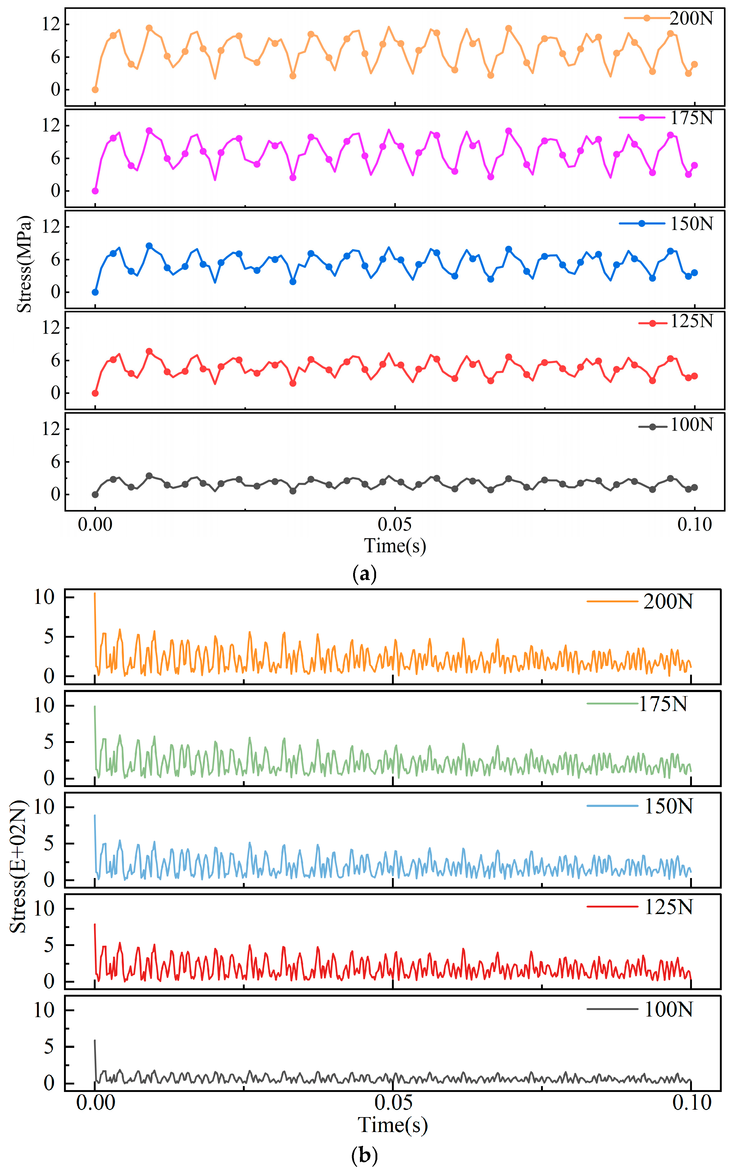
To further reveal the dynamics of de-icing, the contact-force response and equivalent stress from the simulation were analyzed. Since the trends are consistent across cases, a representative case of 10 mm ice with
Fc = 35 N and
Fp = 100–200 N is presented in
Figure 10. Both the force response and equivalent stress exhibit periodic fluctuations, corresponding to the cyclic “contact–compression failure–peeling” process. When
Fp increases from 100 N to 200 N, the force-response range expands from 0–200 N to 0–500 N, and the equivalent-stress range increases from 0–3 MPa to 0–12 MPa. This indicates that higher thrust increases both global load and local stress, strengthening the cyclic failure effect. Over time, the equivalent stress maintains a stable periodic pattern, implying repeated attainment of the yield/failure condition in the contact zone, whereas the fluctuation amplitude of the force response gradually decays, consistent with progressive crack initiation and growth that reduce the overall structural strength of the ice layer during removal.
Overall,
Figure 9 indicates that, under purely mechanical de-icing, the ice removal ratio increases markedly with mechanical parameters at first and then gradually saturates; thicker ice consistently results in a lower removal level and a stronger dependence on mechanical loading.
Figure 10 provides a dynamic explanation: de-icing is essentially a cyclic failure process driven by repeated wheel–ice contact. Increasing mechanical parameters (e.g.,
Fc and
Fp) intensifies the damage in the contact zone, facilitating crack initiation and propagation and thus accelerating ice peeling. However, once pronounced cracking has accumulated and the ice layer is continuously weakened, the load required for further breakage decreases, and further increases in mechanical parameters yield only limited improvement in the ice removal ratio. Therefore, the performance gain achievable by simply increasing mechanical loading is inherently bounded and comes at the cost of higher device loads; in comparison, introducing thermal input to reduce ice strength is likely to be a more effective approach.
4.3. Thermo-Mechanical De-Icing Results
4.3.1. Wheel-Temperature-Rise Test
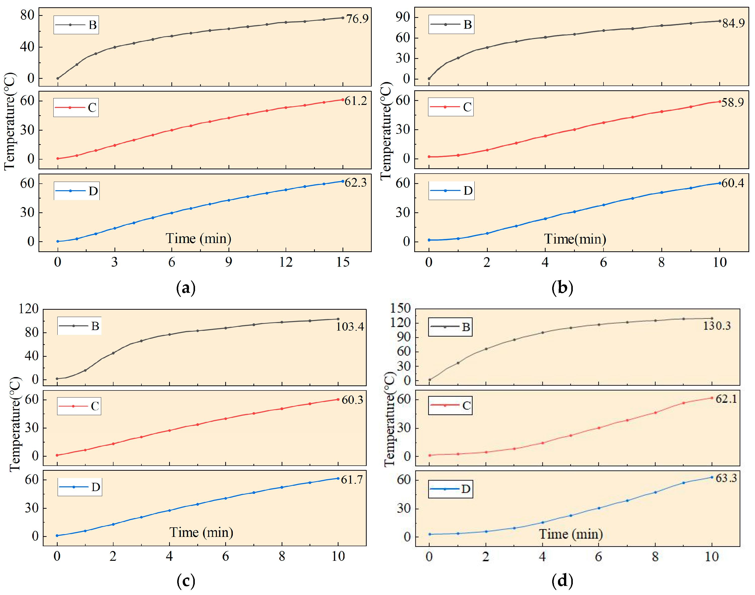
Under a constant 0 °C environment and a sampling rate of 1 Hz, the temperature–time curves at points B, C, and D are shown in
Figure 11. All curves exhibit a “fast-then-slow” heating trend. The temperature at point B is much higher than that at points C and D, and point C remains approximately 1 °C lower than point D. At P = 50 W, the temperature at point B reaches 76.9 °C after 15 min, while points C and D reach 61.3 °C and 62.3 °C, respectively. When the power increases to 60–80 W, points C and D approach 60 °C within 10 min, and the maximum temperature at point B increases with power.
Considering the average stay-cable length in Wuhan and the drive capability of the rotor system, the wheel temperature needs to reach an effective range of 50–60 °C within approximately 10 min. The experimental results indicate that power below 60 W is insufficient; 60 W is marginally acceptable; and 70–80 W provides additional heating margin. However, the temperature-rise rate gradually levels off with increasing power. Considering energy consumption, a power range of 60–80 W is adequate.
4.3.2. Thermo-Mechanical De-Icing Test
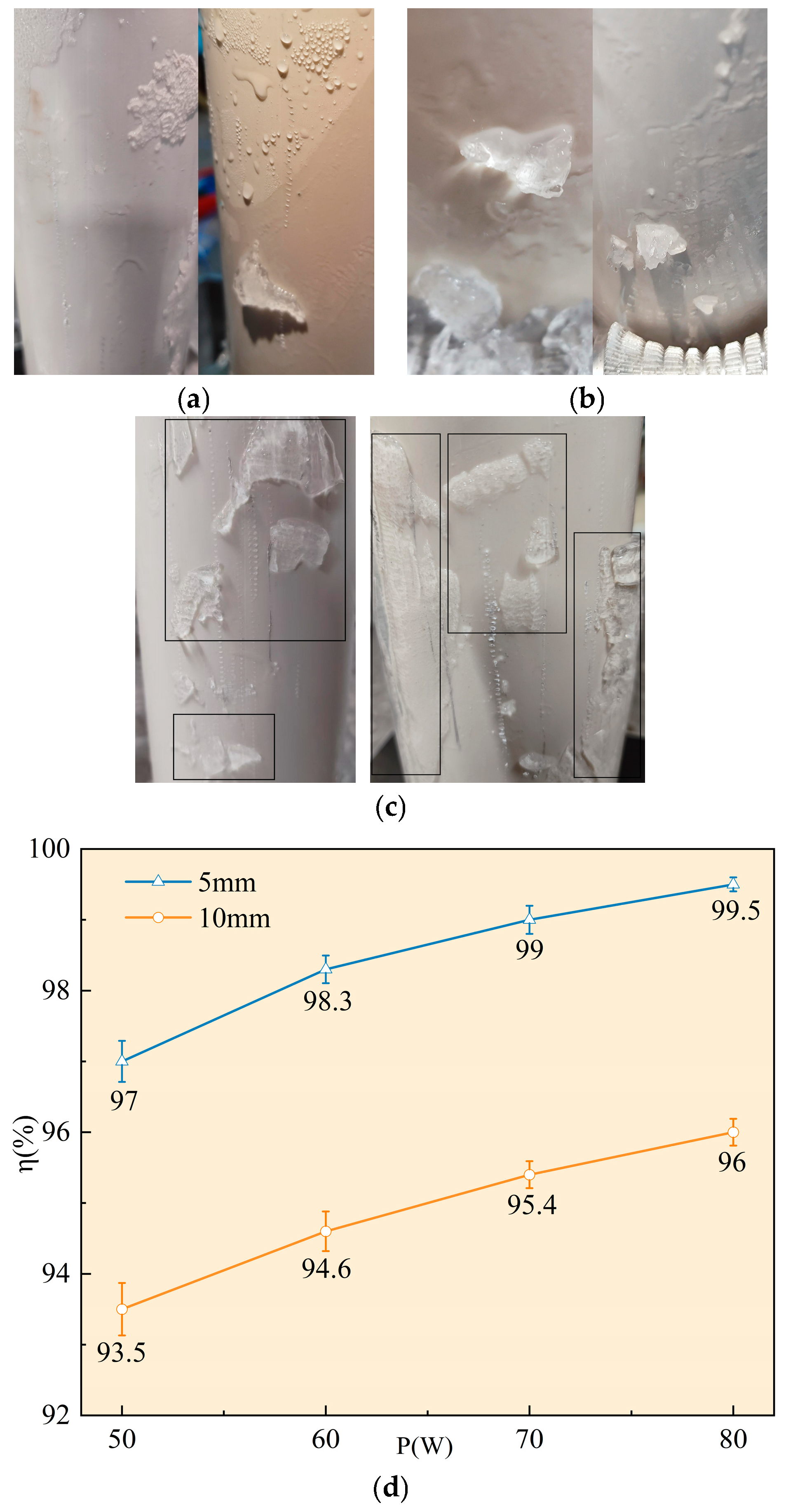
Based on the temperature-rise results, thermo-mechanical de-icing tests were conducted at four power levels (50–80 W) to investigate the effect of power on ice removal. The tests show consistent de-icing behavior across the four power levels: ice in the wheel–ice contact zone melts rapidly, fractures, and is promptly expelled; the wheel path remains clear, and no slipping or interruption occurs. As shown in
Figure 12a,b, for 5 mm ice, the sheath surface after de-icing shows visible wet traces and an extremely thin ice film. Residual ice is discretely distributed with equivalent areas below 100 mm
2 (small-size residuals), with rounded edges and no typical brittle fracture surfaces. For 10 mm ice, the wet region decreases; residual ice remains discretely distributed without obvious brittle fracture surfaces, with a small amount of medium-size residuals and no large-size residuals.
For comparison,
Figure 12c shows the purely mechanical de-icing results. For 5 mm ice, fracture and peeling are achieved, but residual fragments remain relatively numerous, indicating that removal is still dominated by brittle fragmentation with dispersed residuals. When the thickness increases to 10 mm, residual ice becomes significantly larger and exhibits clear scraping marks, indicating that the ice has been mechanically cut but lacks effective through-thickness failure and complete peeling, resulting in the “scraped but not fully removed” behavior under thick-ice conditions. Overall, thermo-mechanical coupling reduces fragment residuals for 5 mm ice and suppresses large-block residuals for 10 mm ice, improving removal completeness for both thin and thick ice.
The ice removal ratio under each power level is shown in
Figure 12d. For 5 mm ice,
= 97–99.5%, with the repeatability error controlled within approximately ±(0.1–0.3)%; for 10 mm ice,
= 93.5–96%, with the repeatability error controlled within approximately ±(0.2–0.4)%. The variation is below 3% for both thicknesses, indicating a minor influence of power on η. The
–power curve shows a more pronounced increase from 50 W to 60 W, followed by saturation. In summary, when the initial temperature is ensured, power mainly affects the heating rate and temperature stability, and provides limited improvement in
once stable removal is achieved.
4.3.3. Thermal-Balance Test
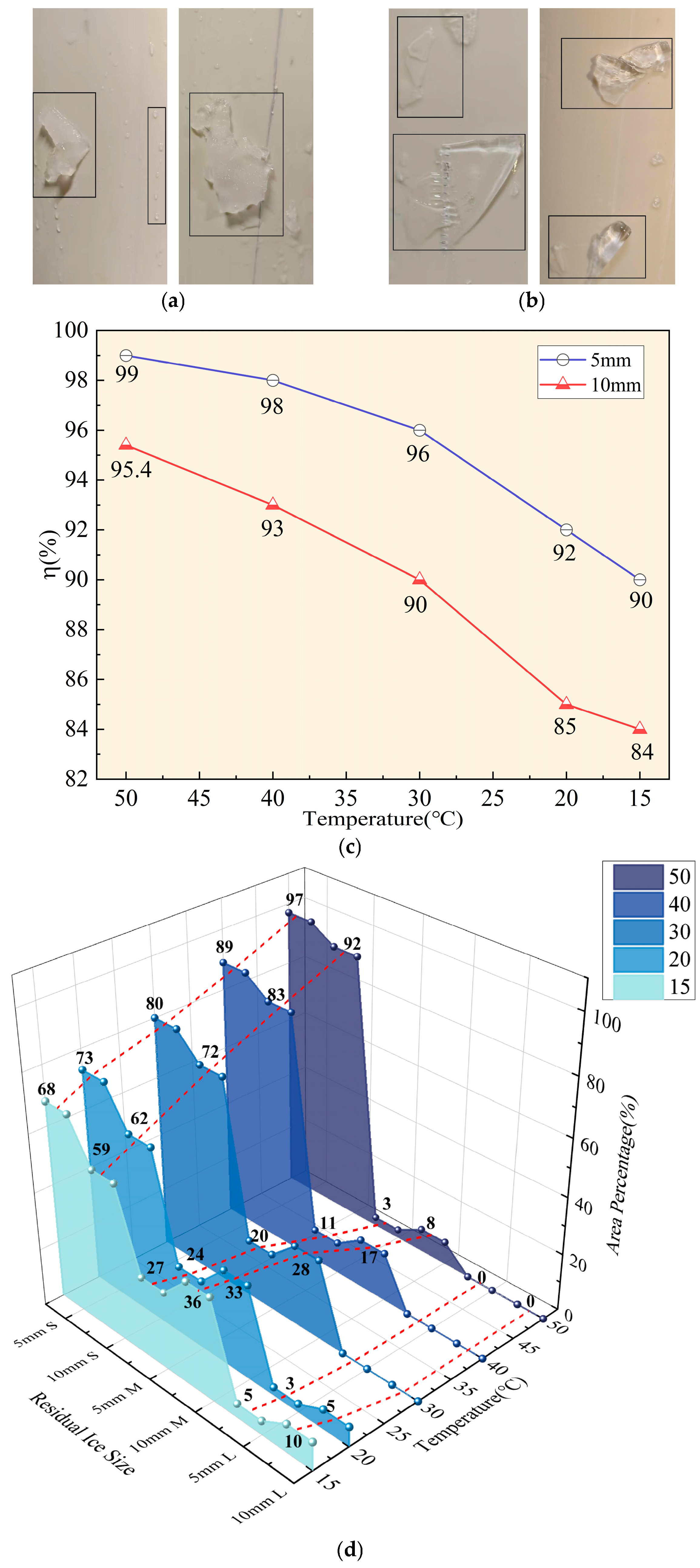
Under four power levels (50–80 W), the final thermal-equilibrium temperature of the wheel remains in a narrow range of approximately 13.8–15.5 °C. Therefore, 70 W was selected as a representative condition, and tests were conducted with initial temperatures of 50 °C, 40 °C, 30 °C, 20 °C and 15 °C, while keeping other parameters unchanged.
The tests show that as the initial temperature decreases from 50 °C to 15 °C, de-icing remains continuous without interruption or slipping, but the softening capability gradually weakens and the residual-ice morphology transitions from a high-temperature thermo-mechanical state toward purely mechanical removal. At 50 °C, the ice removal ratios are 99% (5 mm) and 95.4% (10 mm), as discussed above. At 40–30 °C, residual ice for 5 mm remains fine and mostly small in size, with
decreasing from 98% to 96%; for 10 mm, residual ice slightly increases with some medium-size patches, wet traces decrease, and
drops from 93% to 90% (
Figure 13a). When the initial temperature further decreases to 20–15 °C, de-icing performance weakens (
Figure 13b): for 5 mm, residual ice increases and is mainly medium-sized, with
decreasing from 92% to 90%; for 10 mm,
decreases from 85% to 84%, with a small amount of large-size residuals and clear fracture surfaces, indicating that the fracture is mainly mechanical with limited thermal softening.
To quantify the influence of temperature, the residual-ice size distribution was analyzed (
Figure 13d). As the initial temperature decreases systematically from 50 °C to 15 °C, the area fraction of small-size residuals decreases continuously, while the fractions of medium and large residuals increase. For 10 mm ice, the small-residual fraction decreases from about 93% to about 52%, the medium-residual fraction increases from 7% to 38%, and large residuals appear from 20 °C and reach about 10% at 15 °C. A higher fraction of small residuals indicates more thorough fragmentation and peeling, corresponding to higher
; conversely, increased medium/large residuals indicate weakened mechanical fragmentation and more block-like retention, leading to lower
. Thus, residual-size statistics confirm that temperature influences the ice softening state and fracture behavior, thereby affecting de-icing dynamics and the final ice removal ratio.
Overall: (1) the temperature-rise test confirms insufficient heating at 50 W and rapid heating to the target temperature at 60–80 W; (2) in thermo-mechanical de-icing, increasing power from 50 W to 80 W increases (5 mm: 97–99.5%; 10 mm: 93.5–96%); and (3) the thermal-balance test shows a thermal-equilibrium temperature of 13.8–15.5 °C under 50–80 W, and decreases as the initial temperature drops from 50 °C to 15 °C (5 mm: 99–90%; 10 mm: 95.4–84%). Residual-size statistics further reveal micro-level changes in de-icing dynamics under thermo-mechanical coupling and explain the observed trend of η.
4.4. Comparative Analysis
From
Table 3, neglecting numerical simulation errors, for 5 mm ice, under purely mechanical de-icing with clamping forces of 25–45 N and thrust forces of 100–200 N, the ice removal ratio ranges from 20% to 96%, indicating strong dependence on mechanical loading. Under thermo-mechanical de-icing with
Fc = 35 N and
Fp = 150 N, the ice removal ratio increases significantly to 90–99%. For 10 mm ice, the corresponding ranges are 7–92% for purely mechanical de-icing and 84–95.4% for thermo-mechanical de-icing, demonstrating the clear superiority of thermo-mechanical operation.
Equation (10) represents piecewise linear interpolation, assuming that the relationship between adjacent data points is approximately linear, thereby allowing the inverse estimation of the parameter value required to reach a target ice removal ratio.
In Equation (10), is the reference ice removal ratio, and denotes the value of a given parameter (thrust force, clamping force, or temperature). When analyzing the relationship between thrust and ice removal ratio, x corresponds to the thrust force; similarly, when interpolating clamping force or temperature, represents the clamping force or temperature, respectively. , , and correspond to three parameter values associated with ice removal ratios , , and , where < < . In Equation (11), is the equivalence coefficient; denotes the thrust required to achieve the same ice removal ratio η under parameter value ; and is the reference value used for equivalence conversion. This formulation allows the contributions of different parameters (clamping force or temperature) to be compared in terms of equivalent thrust.
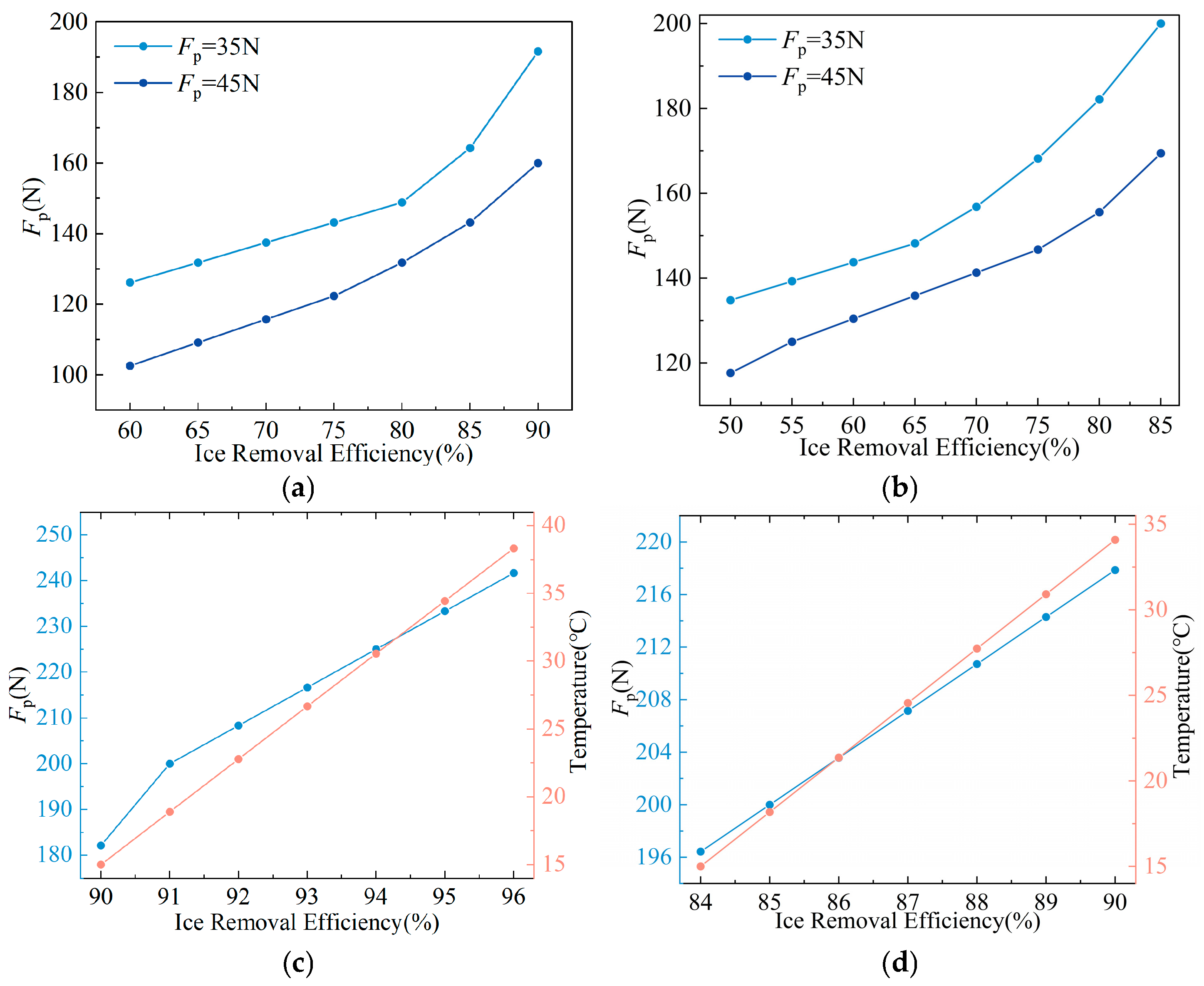
To evaluate the relative contributions of different parameters to ice removal performance, equivalence conversion among thrust, clamping force, and temperature at the same ice removal ratio was established using the interpolation method. Although this equivalence cannot fully reveal the underlying relationship, it provides a clearer comparison of the relationships between these parameters and the ice removal ratio within the tested range, and offers a preliminary reference for future engineering applications, as shown in
Figure 14.
Figure 14a,b show that the equivalence trends between mechanical parameters are similar for different ice thicknesses. As the ice removal ratio increases, purely mechanical de-icing requires progressively higher mechanical inputs. The relationship between thrust and clamping force remains relatively stable across most of the range. For 5 mm thick ice, each additional newton of clamping force is equivalent to approximately 2.26 N of thrust. For 10 mm thick ice, the average equivalence is about 1.89 N of thrust per newton of clamping force. However, at high removal ratios (80–85%), the equivalence becomes more pronounced, reaching about 2.85 N of thrust per newton of clamping force, which is consistent with the role of clamping force in promoting through-thickness failure.
Under thermo-mechanical conditions, due to the generally high ice removal ratio, the equivalence analysis was conducted by comparing thermo-mechanical de-icing at Fc = 35 N with purely mechanical de-icing at Fc = 45 N. This comparison was adopted because thermo-mechanical de-icing at a lower clamping-force level had already achieved a removal-performance range close to that of purely mechanical de-icing at a higher clamping-force level, which helps illustrate the role of thermal assistance in reducing mechanical demand. The results show that, for 5 mm ice, each 1 °C increase in temperature is equivalent to approximately 2.14 N of thrust, while for 10 mm ice, the equivalence is about 1.12 N/°C.
From the perspective of unit conversion efficiency, the equivalent thrust per 1 °C temperature increase is lower than that per 1 N increase in clamping force on average. However, at 15 °C, the temperature-to-thrust equivalence increases significantly, reaching approximately 3.93 N/°C for 5 mm ice and 2.94 N/°C for 10 mm ice. This indicates that temperature introduction has a pronounced effect on enhancing ice removal performance, although its marginal benefit decreases as temperature increases. Moreover, since temperature can be increased over a relatively wide range in practical systems (exceeding 50 °C), the cumulative equivalent thrust gain from thermal input can reach 50–100 N, thereby substantially enhancing the final ice removal capability of the de-icing device.
5. Conclusions
This study proposes a quadrotor-assisted stay-cable de-icing device and experimentally investigates the de-icing performance of its de-icing mechanism under different working conditions. For a representative cable diameter of 90 mm and two typical ice thicknesses (5 mm and 10 mm), the following conclusions are drawn:
The proposed device integrates a split-type openable frame, an arc-shaped milling de-icing wheel, and an embedded heating module. Although the quadrotor mobility module has not been validated through field tests, its feasibility has been supported at the design and component-selection level. Further full-system and outdoor validation will be carried out in future work. The ice specimens used in the de-icing experiments are comparable to actual stay-cable icing conditions in key physical parameters. The present results indicate that the proposed de-icing mechanism shows promising applicability under the representative indoor conditions considered in this study.
Under purely mechanical de-icing conditions, the ice removal process is jointly governed by the clamping force Fc and the axial thrust force Fp. Increasing either parameter improves the ice removal ratio; however, the improvement gradually diminishes as the ice layer becomes progressively damaged. When Fc is insufficient, the ice removal ratio remains low even with increasing thrust, whereas once a critical clamping level is reached, thrust plays a more dominant role in promoting continuous peeling and removal.
Thermo-mechanical coupling significantly enhances de-icing performance for both thin and thick ice layers. Compared with purely mechanical de-icing, the introduction of heating weakens ice strength and reduces interfacial adhesion, enabling high ice removal ratios under lower mechanical loads. In the tested range, thermo-mechanical de-icing consistently achieved ice removal ratios above 84% for 10 mm ice and above 90% for 5 mm ice, indicating its robustness across different icing conditions.
Parameter equivalence analysis shows that temperature input can be effectively converted into an equivalent reduction in mechanical demand. On average, an increase of 1 N in clamping force corresponds to approximately 1.89 N–2.26 N of equivalent thrust, while an increase of 1 °C corresponds to approximately 1.12 N–2.14 N of equivalent thrust. At low temperature levels, the temperature-to-thrust equivalence is further amplified, highlighting the high efficiency of thermal input in reducing mechanical load requirements, although a diminishing-return effect is observed with increasing temperature.
Based on the present results, a set of de-icing parameters can be proposed for engineering reference. For thin ice of 5 mm or less, purely mechanical de-icing is recommended, with Fc = 35–45 N and Fp = 150–200 N. For ice thicknesses of 5–10 mm or relatively thicker icing conditions, thermo-mechanical de-icing is more suitable; favorable performance was obtained under Fc = 35 N, Fp = 150 N, and P = 60–80 W.
These results show that thermo-mechanical coupling is particularly effective when higher removal ratios are required or when the allowable mechanical load is limited, and they provide useful guidance for the design and parameter optimization of stay-cable de-icing devices under complex icing conditions.