1. Introduction
With the increasing frequency and intensity of earthquakes, interest in seismic design has grown significantly. In particular, the seismic behavior of pile-supported structures involves complex soil–structure interactions, making accurate predictions crucial. Traditional seismic design approaches often rely on simplified two-dimensional (2D) analyses, which fail to fully capture the intricate behavior of actual soil–structure systems. Consequently, the necessity of three-dimensional (3D) analysis methods has become more evident. Examining real earthquake damage cases, the 1995 Hanshin-Awaji earthquake (magnitude 6.9) in Japan resulted in severe structural failures due to foundation damage, even for pile-supported structures. Similarly, the 2011 Great East Japan earthquake (magnitude 9.0) led to widespread liquefaction, causing excessive settlement and tilting of many pile-supported structures. More recently, the 2023 Türkiye–Syria earthquake highlighted significant structural collapses due to inadequate seismic performance. These cases underscore the need for a more comprehensive analysis of pile-supported structures under seismic loads and the refinement of design criteria.
The seismic behavior of pile foundations is influenced by various factors, among which the relative density of the soil and the mass of the superstructure are critical parameters. The relative density of the soil determines the magnitude and direction of kinematic forces transmitted through the piles. During seismic events, ground deformation generates soil kinematic forces, which are then transferred to the pile foundation and ultimately to the structure. In dense soils, the deformation is relatively small, and higher soil stiffness results in greater kinematic forces being transmitted to the piles. Conversely, in loose soils, significant ground deformation leads to increased seismic wave attenuation, but excessive soil movement around the piles can complicate their behavior. Low relative density increases the risk of pile buckling, whereas high relative density leads to greater internal stress, potentially elevating the likelihood of structural damage.
The mass of the superstructure plays a crucial role in determining the magnitude of inertial forces generated during an earthquake. According to Newton’s second law (F = ma), a larger superstructure mass results in greater inertial forces under seismic acceleration. These forces impose additional horizontal and vertical loads on the pile foundation, increasing bending moments and shear forces in the piles. However, an increased superstructure mass also lowers the structure’s natural frequency, potentially reducing the likelihood of resonance with seismic waves and thereby mitigating seismic response. The interplay between inertial and kinematic forces necessitates a comprehensive understanding of soil–structure interaction.
Traditional experimental and 2D numerical methods are often insufficient in capturing the full complexity of pile–soil–structure interactions. Physical model tests are constrained by scale effects, limiting their ability to replicate actual soil–structure interactions under seismic loads. Likewise, 2D numerical analyses fail to account for the three-dimensional effects of seismic loading on piles and soil. Particularly in pile groups, interactions between adjacent piles, asymmetric soil responses, and localized stress concentrations must be considered. Given these limitations, this study employs 3D numerical analysis using FLAC3D to provide a more precise evaluation of the seismic response of pile-supported structures.
Several studies have investigated the seismic behavior of pile-supported structures, focusing on different influencing factors. Reference [
1] reveals that kinematic interaction significantly influences pile behavior in both liquefiable and non-liquefiable sites, with inertial interaction affecting pile failure modes differently. Reference [
2] highlights that earthquake magnitude significantly influences the dynamic behavior of soil–pile foundation systems. Kinematic interaction analyses reveal that layered soil conditions, particularly when 75% of the pile length is in weak soil, create unfavorable scenarios during seismic events. Reference [
3] indicates that during dynamic soil–pile–structure interaction in dry sand, inertial forces from the superstructure dominate, while kinematic forces from soil deformation are relatively insignificant. Reference [
4] focuses on dynamic soil–pile behavior during liquefaction, highlighting the influence of excess pore pressure and soil nonlinearity on structural responses. It emphasizes the differences in interactive behavior between liquefied and dry sand under cyclic loading conditions. Reference [
5] analyzed the influence of soil relative density on pile deformation and seismic response. The authors’ findings indicate that higher relative densities reduce pile deformation, enhancing overall stability. Reference [
6] studied the effect of superstructure mass on pile foundations under seismic loading. The authors observed that while an increase in mass generally amplifies inertial forces and bending moments in piles, beyond a certain threshold, seismic response diminishes due to reduced resonance. Reference [
7] examined the interaction between kinematic and inertial forces, highlighting that denser soils and heavier superstructures intensify these interactions, significantly affecting pile seismic performance. Reference [
8] investigated pile behavior in liquefied soils, demonstrating that lower relative densities increase the risk of buckling and lateral displacement, which can compromise structural integrity. Reference [
9] examined how soil relative density affects the lateral response of piled raft foundations. Higher density increased stiffness, reducing lateral displacement and shifting more load resistance to the raft component. Previous studies have primarily focused on analyzing these effects separately, with limited research investigating the combined interaction of kinematic and inertial forces. Furthermore, a comparative analysis of the seismic behavior of single piles and pile groups remains necessary to provide practical seismic design guidelines. Several other studies have attempted to evaluate the dynamic interaction behavior of soil–pile–structure using various methods such as numerical analysis techniques [
10,
11,
12,
13,
14,
15]. However, it is difficult to view them as studies focused on inertial and kinetic forces.
This study aims to analyze the seismic behavior of group pile-supported structure using 3D numerical simulations with FLAC3D. The focus is on evaluating the effects of soil relative density and superstructure mass on the seismic response of pile foundations by examining the interplay between kinematic and inertial forces. Through quantitative comparisons, this study seeks to identify key factors influencing the seismic response of pile-supported structures and provide valuable insights for improving seismic design. Furthermore, this research addresses the existing gap in previous studies by comprehensively investigating the dynamic interaction of kinematic and inertial forces using a 3D approach. The findings are expected to contribute to the optimization of seismic design for pile foundations.
2. Modeling Methodology
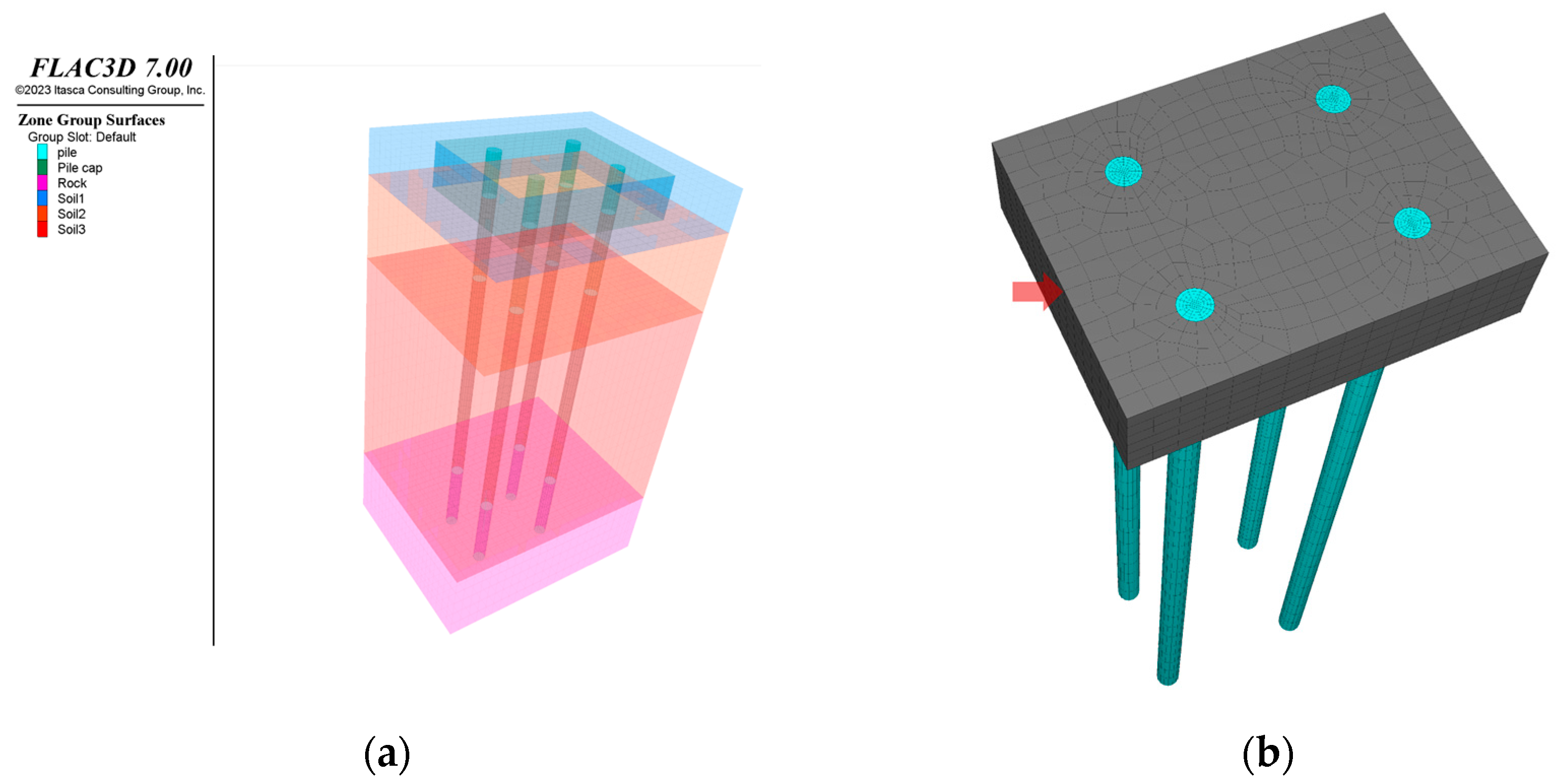
In this study, a partial segment of a bridge structure supported by a 2 × 2 group pile foundation was adopted as a prototype to evaluate the seismic response of superstructures supported by pile foundations. The model system was designed to represent actual bridge and subsoil conditions in Cheonan, Chungcheongnam-do, South Korea. To systematically analyze various seismic response conditions, soil conditions and input parameters of the superstructure were parametrically varied. The general specifications of the prototype structure are depicted in
Figure 1. The foundation consists of a 2 × 2 configuration of steel pipe piles, with a pile cap measuring approximately 4 m in width, 3 m in length, and 1.6 m in height. The piles are steel pipe piles with a diameter(Φ) of 502 mm, thickness(t) of 12 mm.
A three-dimensional continuum modeling method based on the finite difference method (FDM) was employed to assess the dynamic response of the bridge foundation under seismic loading. FLAC3D 7.0 [
16], a widely used commercial software in geotechnical and foundation engineering, was utilized for this analysis. The soil model was implemented using the Mohr–Coulomb elasto-plastic model, and the input soil properties of the subsurface layers were derived from the site-specific geotechnical investigation report of the actual target location. The stratigraphy primarily consists of silty sand overlying weathered rock, and the material properties of each soil layer are detailed in
Table 1 and
Figure 2. In this study, the input material properties for silty sand with two different relative densities were determined according to the analysis cases described below. The estimation of material properties considered key geotechnical characteristics, including shear strength and deformation modulus, as functions of relative density. The material parameters were derived based on empirical formulas presented in previous studies and relevant literature. The total depth of the soil model was set to 11 m, consistent with the pile foundation length, to simulate the embedment condition in the weathered rock.
The pile foundation and pile cap structures were modeled using an elastic constitutive model, and the key material properties for each structural component are presented in
Table 2. The pile foundation was simulated as steel pipe piles (Φ502, 12t). However, for computational convenience, they were modeled as solid circular piles. To maintain equivalent flexural rigidity to the actual steel pipe piles, the diameter was adjusted to Φ329. The pile length was set to 11 m according to the design drawings, ensuring an embedment depth of 2 m into the weathered rock layer. The pile cap was modeled as a reinforced concrete structure with dimensions of approximately 4 m in width, 3 m in length, and 1.6 m in height.
Figure 2 shows the layout of the structural model.
Structures that are either in contact with or embedded within the soil exhibit different dynamic behaviors from the surrounding ground due to material heterogeneity under seismic excitation. When significant stiffness contrasts exist between the structure and the surrounding soil, and when substantial external loads are applied, dynamic soil–structure interaction (SSI) becomes pronounced, leading to response deviations from those predicted under fixed-base assumptions. Therefore, an interface model was incorporated to explicitly account for soil–structure interaction effects, including potential slippage and separation between the structure and the surrounding soil under seismic loading. The interface model was applied to all contact surfaces of the foundation structure, as illustrated in
Figure 3, and consisted of five key interaction zones: (1) the lateral interface between the pile cap and the uppermost soil layer, (2) the interface between the pile cap base and the second soil layer, (3) the interface between the piles and the second and third soil layers, and (4) the interface between the piles and the weathered rock. Each interface area is marked with a different color in
Figure 3. The actual field soil conditions consisted of four different strata, but in this study, a single stratum was simulated for parametric study according to the difference in soil relative density, so the material properties of Interfaces 1, 2, 4, and 5 were entered identically. The layout for the interface model is depicted in
Figure 3, and the primary input parameters for the interface model included normal and shear stiffness as well as the internal friction angle, as summarized in
Table 3.
Another critical aspect in the dynamic analysis of numerical models with a limited number of elements is the boundary condition. To mitigate errors arising from wave reflections at the model boundaries, a quiet boundary condition was applied to both lateral faces of the model along the
x-axis. This approach ensures that seismic waves propagating towards the boundaries are absorbed rather than reflected, effectively simulating the response of a semi-infinite soil domain. The input seismic motion was applied to the model base as a velocity-time history in the x-direction, while responses in the y-direction were constrained.
Figure 4 depicts the composition of model boundary conditions.
The dynamic analysis procedures for the developed three-dimensional continuum model are outlined as follows. Initially, a geo-static equilibrium analysis was performed to verify the numerical stability including mesh convergence and static equilibrium of the model. Subsequently, dynamic analysis was conducted. The seismic loading applied at the model base propagated through the soil–pile–structure system, ultimately reaching the pile cap. The dynamic response was evaluated at the upper-leftmost point of the pile cap, as depicted in
Figure 5. The extent and nature of soil–pile–structure interaction (SPSI) can significantly influence the superstructure response. While extensive research has been conducted on the effects of inertial and kinematic interactions within SPSI systems, most studies have focused on either one of these effects or have primarily examined pile responses (e.g., acceleration, displacement, and internal forces such as bending moments) rather than superstructure behavior. However, the ultimate objective of seismic design is to ensure serviceability of the superstructure. In pile foundation systems, the superstructure response is primarily governed by the pile cap response, which subsequently serves as the input load for structural analysis. Accordingly, this study focuses on investigating how inertial and kinematic interactions in soil–pile–structure systems differ between single piles and pile groups, and how these interactions influence the seismic response of the superstructure.
The analysis cases considered in this study are summarized in
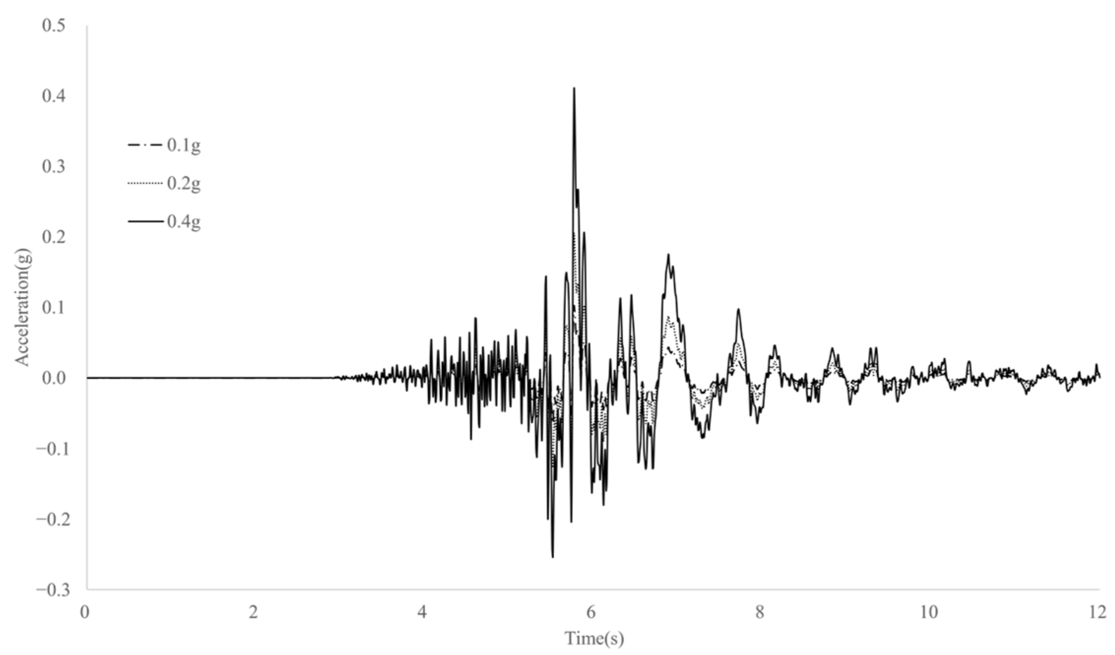
Table 4. The input seismic waves were modified to match the design response spectrum from the north-south (NS) component recorded at the PHA2 station (bedrock motion) during the 2017 Pohang earthquake, accounting for the seismic characteristics of the Korean Peninsula. The NS component corresponds to the larger value of the two seismic waves (NS, EW) measured at the PHS station. Seismic accelerations of 0.1 g, 0.2 g, and 0.4 g were used as input motions and applied at the base of the numerical model. The acceleration-time histories of these input motions are illustrated in
Figure 6. Additionally, to assess the influence of inertial and kinematic interactions in the soil–pile system, two different superstructure mass conditions and two relative soil density conditions were considered. As a result, a total of 12 three-dimensional numerical simulations were conducted. In addition, since velocity and displacement responses are mainly used when evaluating or designing seismic responses of superstructures such as bridges, following analysis results were investigated with a focus on dynamic velocity responses and displacement responses.
4. Conclusions
This study conducted three-dimensional numerical analyses using FLAC3D to assess the seismic response of group pile-supported structures, with emphasis on the interplay between kinematic and inertial effects. A total of 12 simulation cases were developed by varying seismic intensity, soil relative density, and superstructure mass, allowing for a comprehensive evaluation of soil–pile–structure interaction in dry ground conditions.
- (1)
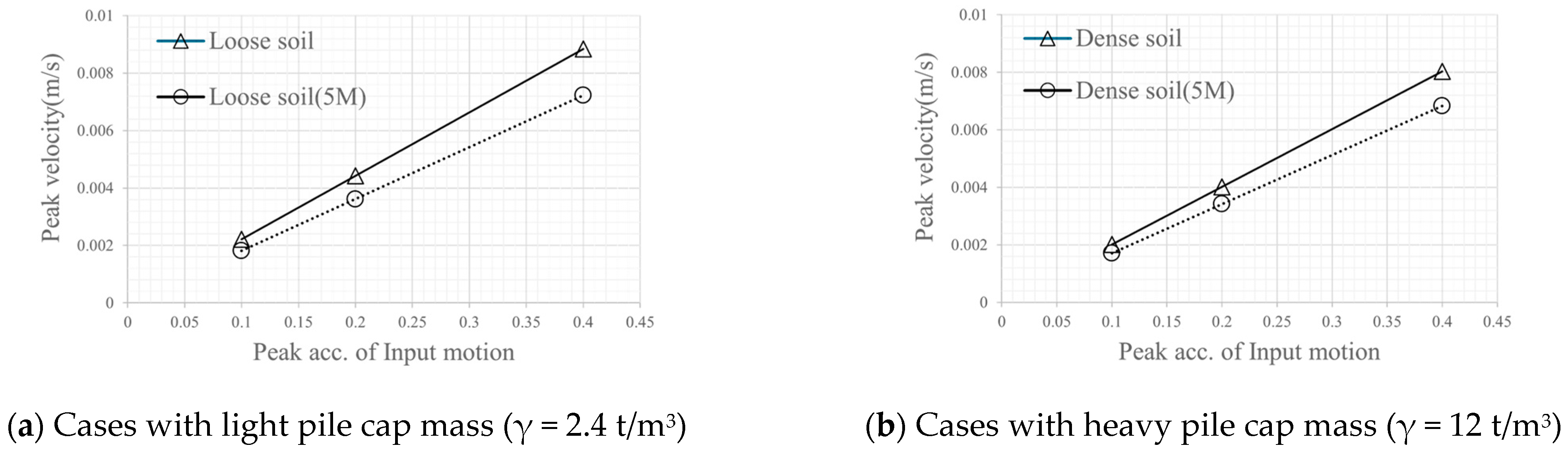
The results reveal that kinematic effects become increasingly pronounced with higher seismic input levels, especially under dense soil conditions. While loose soils exhibited relatively large displacements, the difference in pile cap velocity responses between loose and dense soils grew with increasing seismic intensity. This trend confirms that denser soils, although stiffer, transmit stronger kinematic forces during strong seismic events, which can amplify bending moments in the piles and structural demands on the superstructure.
- (2)
The simulations showed that heavier superstructure mass generally leads to increased inertial forces. However, due to the embedment of the pile cap and the confining effect of the pile group system, the manifestation of inertial effects was limited in terms of pile and pile cap displacements. Interestingly, an increase in pile cap mass introduced a resistive interaction with kinematic effects, reducing differential motions and contributing to more synchronized dynamic responses between pile top and bottom in some cases. This interplay was more evident under dense soil conditions and higher input motions.
- (3)
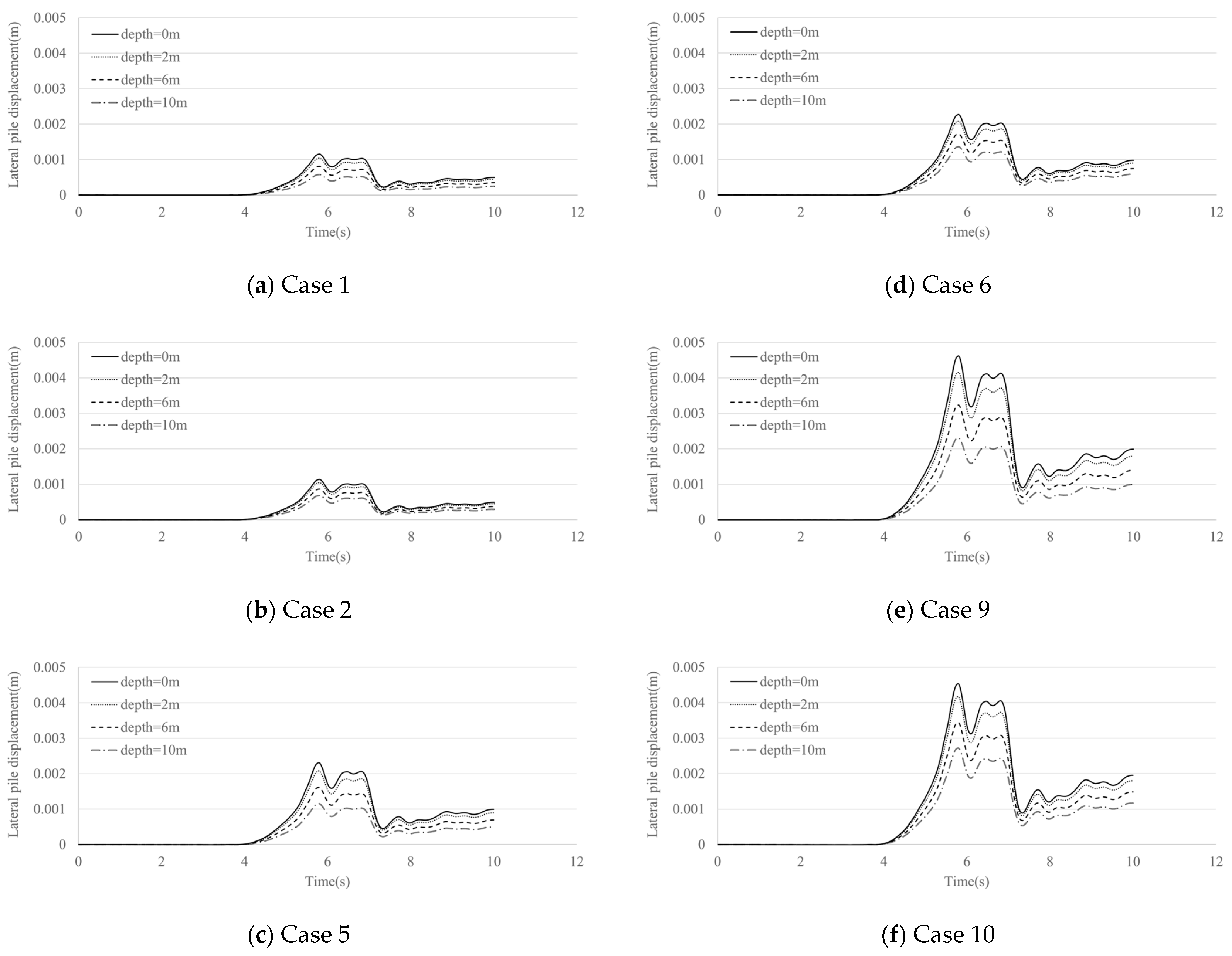
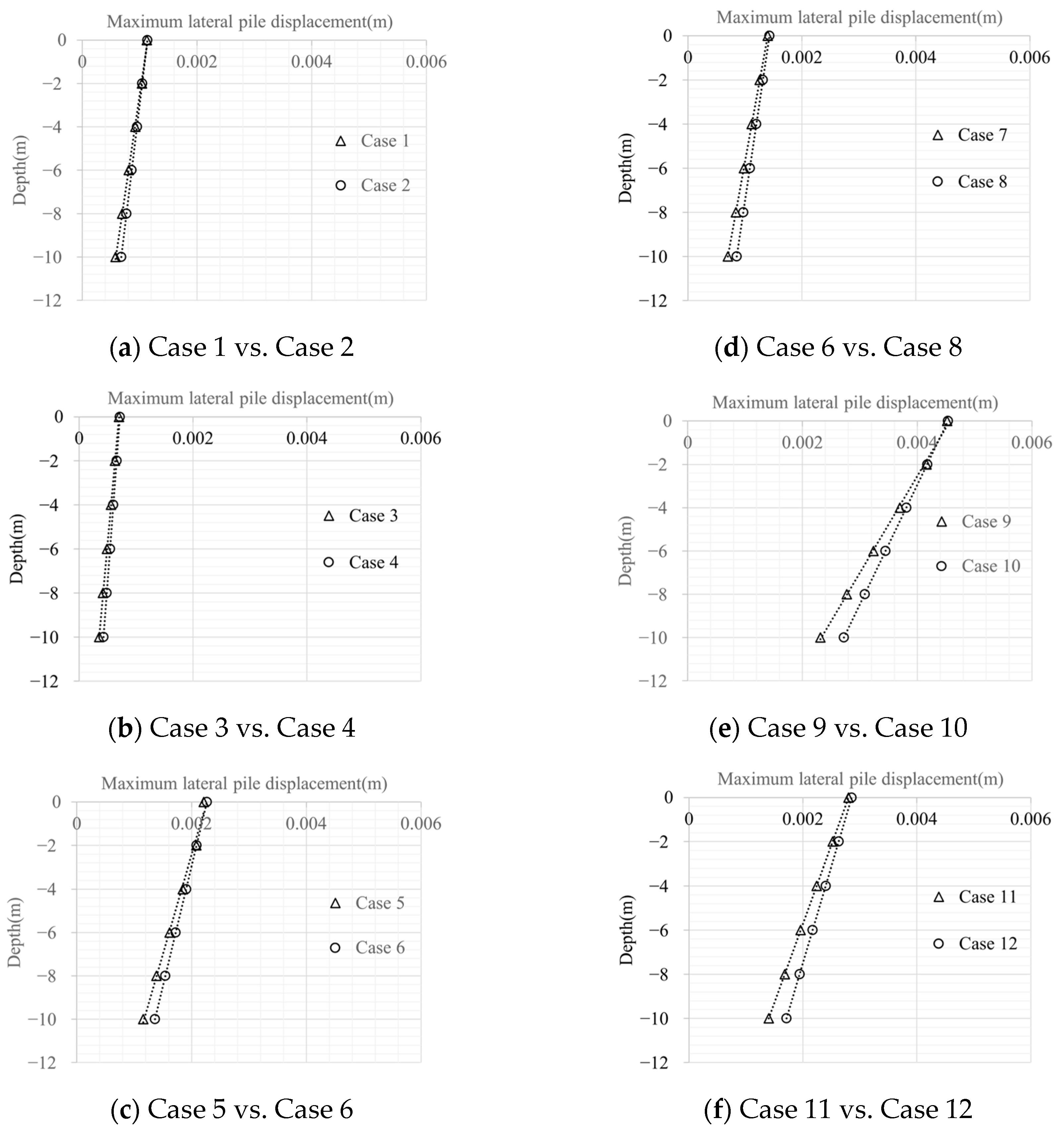
Despite varying soil conditions and seismic intensities, the absolute magnitude of pile displacements remained relatively small (less than 5 mm at pile tops), suggesting limited impact on serviceability for pile group systems with embedded pile caps under dry ground conditions. However, from a structural stability perspective, attention must be paid to stress accumulation in the piles, particularly under dense soil conditions where internal forces intensify due to stronger kinematic interactions. Furthermore, while the current study focuses on dry soil environments, significantly different behavior is anticipated in liquefiable soils, where factors such as strength degradation and lateral spreading can dominate the response.
In conclusion, this study provides valuable insights into the dynamic behavior of pile-supported structures by analyzing the coupled effects of kinematic and inertial forces in a three-dimensional framework. In general, the effect of kinetic force is expected to be large in loose soil (large displacement during earthquake) such as liquefied soil, but it was identified that the effect of kinetic force in dense soil could be more prominent in dry soil conditions when the magnitude of the earthquake is large. In addition, it was identified that the interaction of inertial force and kinetic force acts in the direction of reducing the difference in behavior between the top and bottom of the piles in the condition of pile cap-embedded group piles and that a more economical design is possible when considering this when the superstructure mass increases.
The findings emphasize the importance of considering both soil stiffness and structural mass when evaluating seismic performance and highlight the necessity of tailored design strategies for varying ground conditions. These results can inform more robust seismic design guidelines and serve as a basis for future research involving complex soil–structure interaction phenomena under liquefaction or multi-directional loading scenarios. In order to secure the reliability of the numerical analysis results presented in this paper, further studies will require additional experiments and comparisons with the results, which are expected to provide much improved insight into the interaction of inertial and kinetic forces of the foundation structure. In addition, in terms of the numerical model, it may be necessary to supplement the fact that the soil model used in this paper cannot closely reflect the nonlinear behavior of the soil that may occur during a strong earthquake. This was intentionally not considered in this paper because it focused on the behavior at the top of the structure, and I wanted to utilize an efficient model that can be used in practice as much as possible. However, if the numerical model is supplemented by additionally applying a model that can closely consider the nonlinearity of the ground, such as the decrease in shear modulus due to the increase in shear strain, through further study, it is judged that results reflecting more detailed dynamic responses can be derived. In addition, the practical implications and recommendations for engineers and designers are described as follows. In practice, the inertial and kinetic effects based on the dynamic soil–structure interaction are not widely applied in design. However, the results of this paper are expected to be of great help in terms of stability and economy. First, in terms of stability, for example, if the phenomenon that the kinetic force effect is more severe in dense soil is not properly considered, structural problems may arise at points where the design compactness is relatively low due to the high stiffness of the soil. In addition, in terms of economy, if a serviceability-based design that considers the magnitude of the superstructure displacement is performed, it is expected that much more efficient bridge foundation design will be possible than before.


