1. Introduction
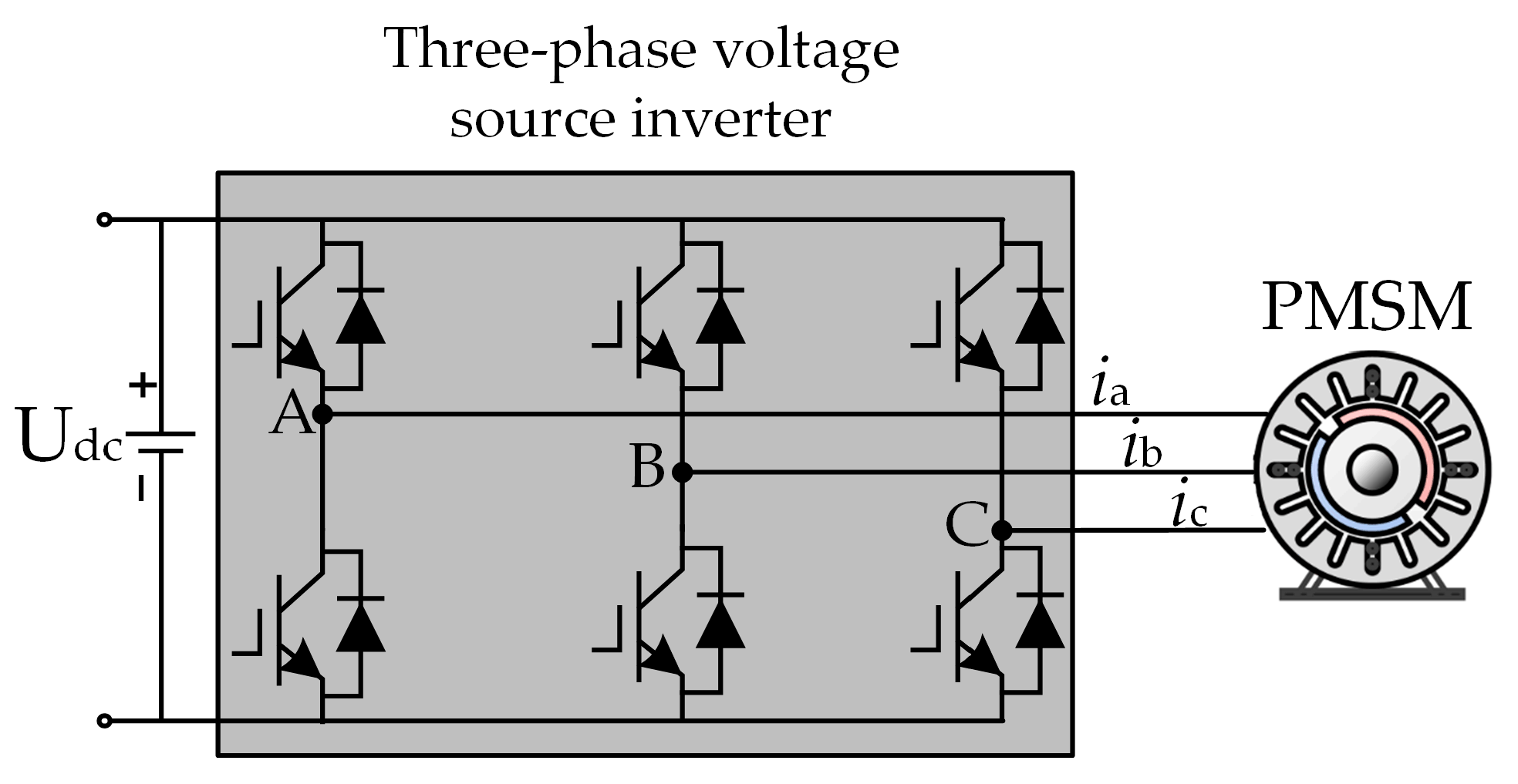
With the deterioration of the global ecological environment and the aggravation of the energy crisis, Electric Vehicles (EVs), as an important carrier of green transportation, have shown explosive growth in market demand and technological innovation. As the core of EVs, the performance of the motor drive system directly determines the energy efficiency, reliability, and user experience of the vehicle. At present, the mainstream inverter control technology—SVPWM—is widely used for its high efficiency, low harmonics, and other advantages. However, the traditional SVPWM adopts the modulation strategy of fixed switching frequency, which leads to the generation of high-amplitude discrete harmonics at the switching frequency and its octave frequency of the inverter power devices, triggering the problems of Electromagnetic Interference (EMI), Noise Vibration Harshness (NVH), etc., and severely restricting the comprehensive control of the electric drive system. This seriously restricts the comprehensive performance of the electric drive system [
1].
In recent years, in order to reduce the high-amplitude harmonics generated by conventional SVPWM, researchers have continuously optimized the conventional SVPWM and proposed various modulation techniques [
2]. For example, Periodic PWM (PPWM) varies the switching frequency periodically (e.g., with the laws of triangle wave, sine wave, and sawtooth wave, etc.), which disperses the harmonic energy that was originally concentrated at a fixed frequency into an extended frequency band centered on the switching frequency, but it introduces side effects such as the increase in current ripple and the decrease in the control accuracy [
3,
4]; Selective Harmonic Elimination PWM (SHEPWM), on the other hand, directly eliminates the harmonic components in the target frequency band by optimizing the combination of switching angles. Taking the three-phase two-level inverter as an example, specific harmonic elimination can be realized without relying on filters by solving a system of nonlinear equations constructed using Fourier series. However, its algorithmic complexity is high and needs to be redesigned for different topologies, which limits its generalization [
5,
6]. Passive suppression means mainly relying on external devices, such as common-mode chokes, RC absorber circuits, or active electromagnetic shields, which can mitigate the harmonic effects but increase the system size and cost and do not solve the problem at the root cause [
7,
8].
Relatively speaking, the RPWM technique, by randomizing the switching frequency or pulse position, uniformly scatters the discrete harmonic energy within a broad frequency domain range, significantly reduces the amplitude of the harmonic energy, and has thereby become a hot research topic at present [
9]. Reference [
10] proposed a randomized switching control method to improve the high-voltage spectrum, but only three switching frequencies were used, and the spectrum distribution was not uniform. Reference [
11] proposed a random switching frequency method for eliminating specific frequency harmonics so that the harmonic spectrum can be uniformly distributed, but the system oscillates at low frequencies and the output waveform fluctuates too much. Reference [
12] proposed a spectral zero method based on the random switching cycle technique, which realizes spectral shaping at the resonance frequency, but it only works at resonance frequencies greater than 20 kHz. Reference [
13] proposed a double random pulse width modulation technique that improves the harmonic expansion factor by about 30% compared to SVPWM, but it causes the low-frequency spreading problem of PWM harmonics, which in turn causes low-frequency noise in the motor. Reference [
14] analyzes the effects of five random modulation strategies on EMI and switching current harmonics of simple and interleaved buck converters and proposes a random carrier frequency fixed duty cycle modulation strategy as the best modulation scheme that can significantly reduce EMI and current harmonics, but the random number generator used has limitations in accuracy and randomness range that can affect the accuracy of the experiment.
However, the core challenge of the RPWM lies in the quality of random number generation [
15]. Ideal uniformly distributed random numbers rely on hardware implementation, which is costly and difficult to integrate into on-board microprocessors, while pseudo-random numbers generated by algorithms such as the linear congruential method have problems such as high sequence repetitiveness and statistical characteristic deviations, leading to incomplete spectrum expansion and even secondary problems such as motor resonance [
16]. Compared with ideal random numbers, pseudo-random numbers may show continuous values greater than or less than the central value in certain time periods, thereby reducing random performance and directly affecting the suppression effect of the RPWM on high-amplitude harmonics.
To address this issue, researchers have proposed numerous approaches, with the Markov chain demonstrating the most significant efficacy. In reference [
17], a two-state Markov chain was employed for random number generation and integrated with the asymmetric SVPWM technique to mitigate high-frequency harmonics in the IMC-PMSM system. In reference [
18], building upon random pulse position modulation, the Markov chain was leveraged to optimize random number generation, thereby improving the suppression of high-frequency sideband harmonics.
In summary, the RPWM technology still has certain limitations at present. Although existing research has optimized the random number performance of the RPWM by using Markov chains, it has not deeply analyzed the reasons for its impact on the RPWM. Based on this, this study takes the permanent magnet synchronous motor as the research object and proposes a control method for permanent magnet synchronous motors based on two-state Markov chain random spread spectrum. Different from the existing literature, this method fully considers the influence of spread spectrum parameters and combines the immune algorithm for parameter optimization to avoid the problem of poor spread spectrum effect caused by human selection. The contributions of this article are as follows:
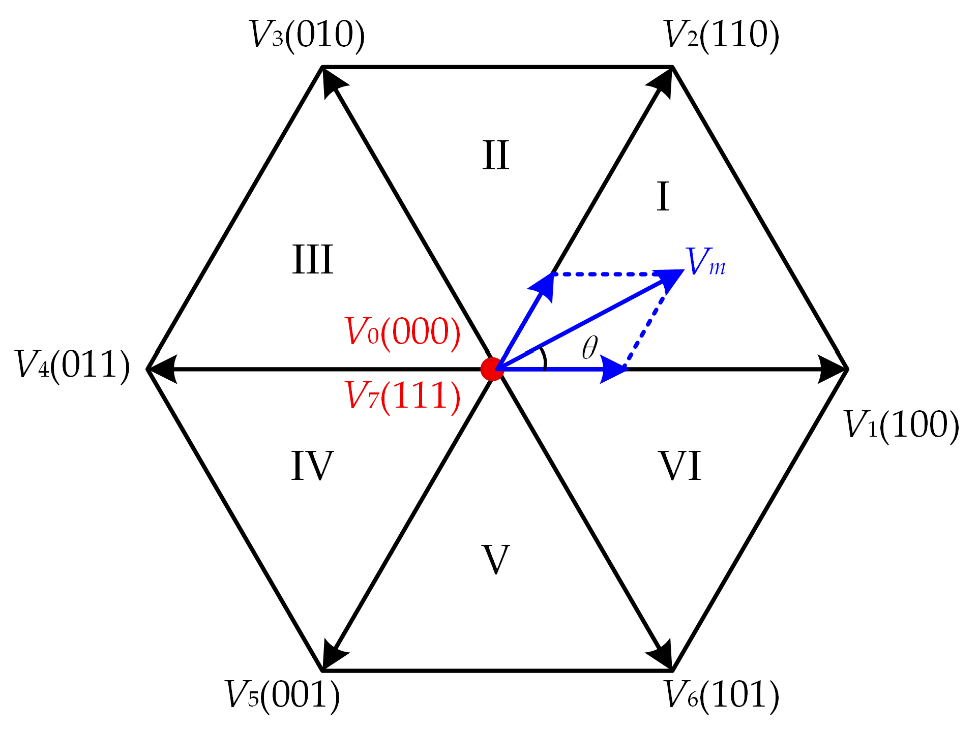
The working principle of the SVPWM is expounded, and the distribution characteristics of its output harmonics are deeply analyzed, laying a foundation for the theoretical analysis of the RPWM;
An RPWM based on a two-state Markov chain is proposed. By introducing the concepts of Markov process and Markov chain, the mathematical model of the two-state Markov chain is derived to optimize the random number performance of the RPWM;
A thorough analysis was conducted on the influence of transition probability and random gain on the two-state Markov chain RPWM, and the immune algorithm was employed to optimize these two key parameters, thereby resolving the issue of ineffective reduction in high-frequency harmonics due to improper parameter selection.
The rest of this paper is organized as follows:
Section 2 introduces the working principle of traditional SVPWM and the analysis of output harmonics.
Section 3 presents the traditional RPWM, followed by the proposal of an improved RPWM technique based on a two-state Markov chain and the use of an immune algorithm to optimize the spread spectrum parameters. In
Section 4, the feasibility and effectiveness of the proposed method are verified through the construction of a permanent magnet synchronous motor experimental platform, and its advantages over traditional methods are demonstrated. In
Section 5, the contributions and methods of this paper are summarized.
3. Random PWM Technique Based Two-State Markov Chain
3.1. Conventional RPWM Technique
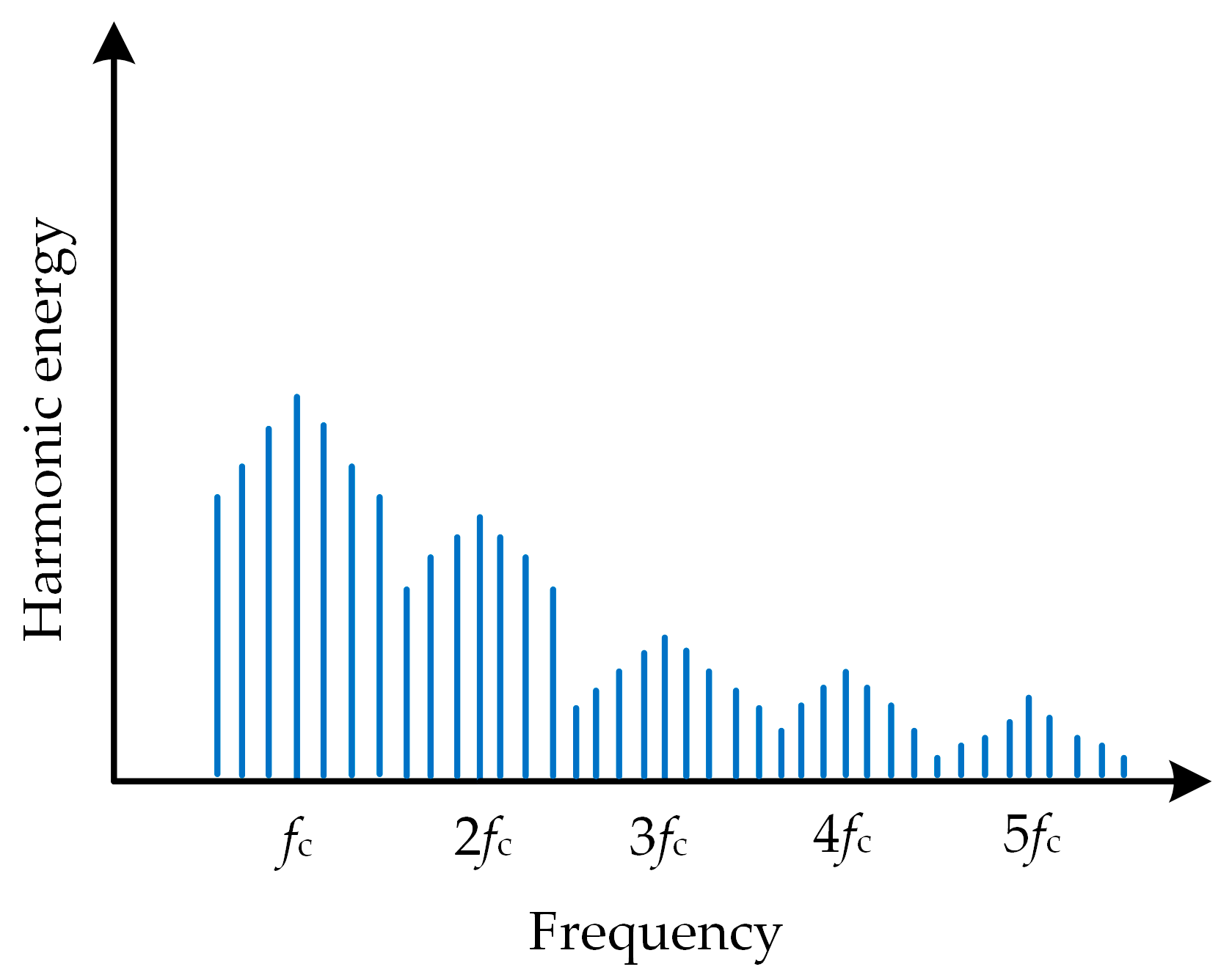
Conventional RPWM is based on Equation (7); the carrier frequency is randomized so that the harmonics at its carrier frequency and its octave are uniformly apportioned in a wide frequency domain, effectively reducing the harmonic amplitude to achieve the purpose of suppressing the EMI of the motor [
23]. The spectral distribution after the spreading of the spectrum is shown in
Figure 4.
The expression for the RPWM is shown below:
where
fr represents the randomized carrier frequency,
fc denotes the desired carrier frequency,
s is a random number that varies within the range of [−1, 1], and
r signifies the random gain, which is expressed as the spreading width.
From the above equation, it can be concluded that the final effect of the random spread spectrum technique is mainly determined by the two parameters of random number
s and random gain
r together, and the carrier frequency variation range is [
fc −
r,
fc +
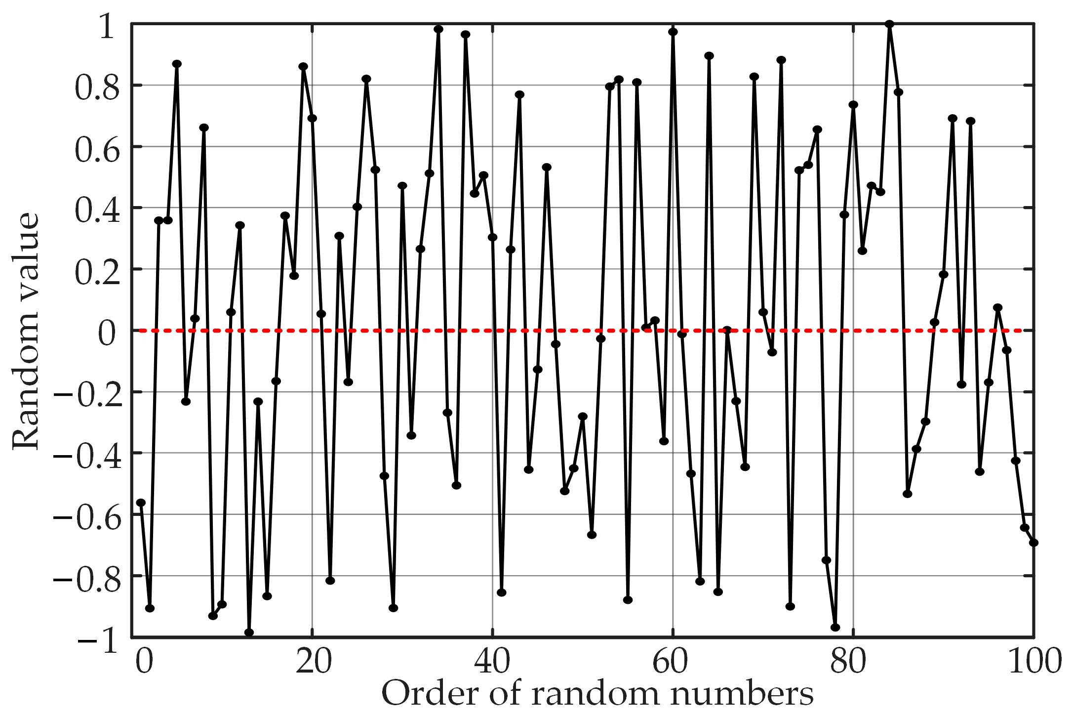
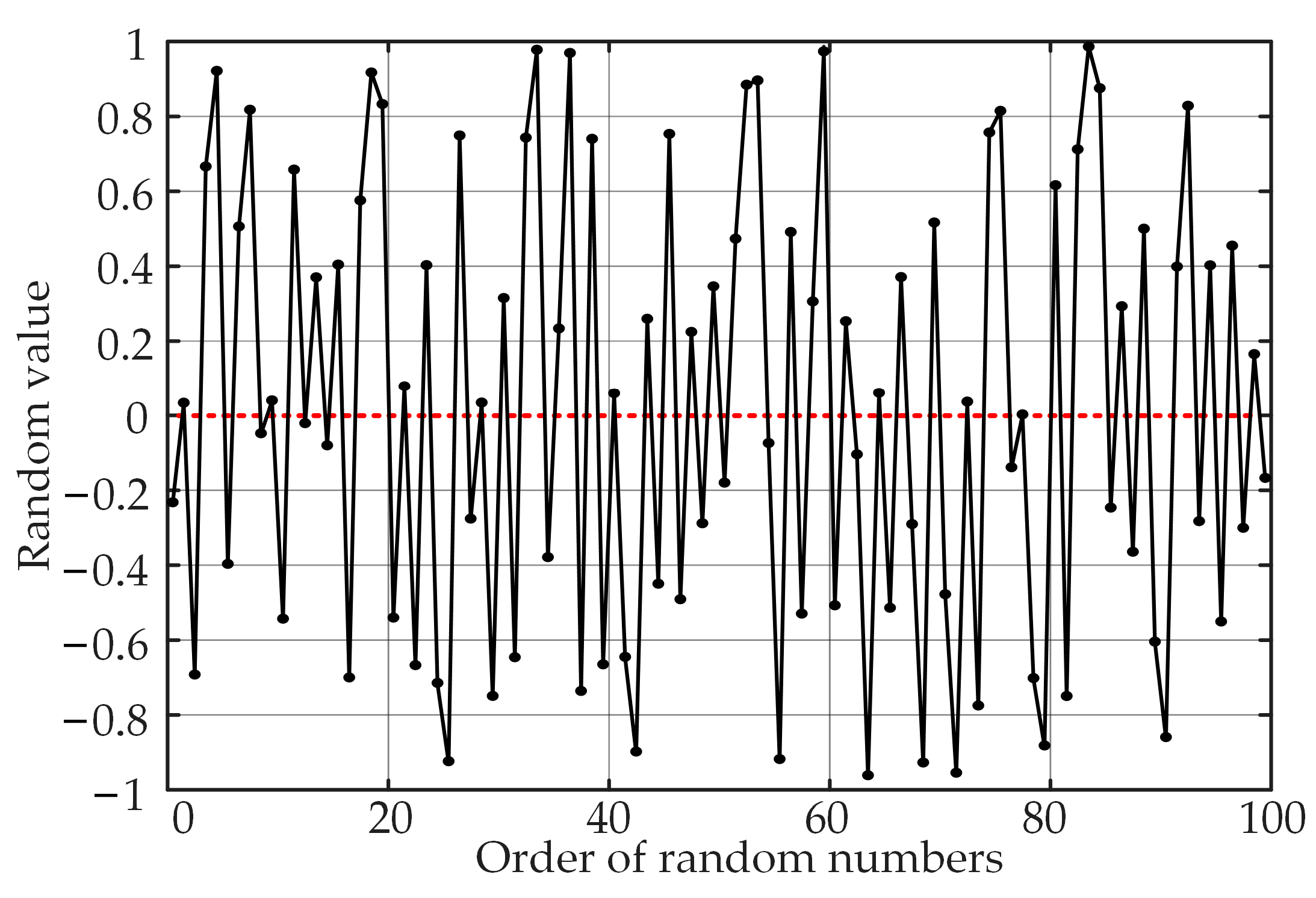
r], and the random number in the traditional RPWM technique is generally generated by the linear congruence method, which does not impose restrictions on the random number generation. Therefore, in the process of random number generation, it will occur in several consecutive cycles if the random value is greater or less than the expected value, as shown in
Figure 5. Thus, the random carrier frequency will also be greater or less than the desired carrier frequency, which ultimately affects the EMI suppression effect of the RPWM.
3.2. RPWM Technique Based on Two-State Markov Chain
In order to solve the problem of unsatisfactory random number generation results mentioned in the previous section, this section introduces the Markov chain into the RPWM technique to improve the random performance of the random numbers, thus further weakening the harmonic peaks.
Markov property refers to the fact that under the condition that the current state is known, the value of the future does not depend on the past; only the current state can predict the future, and the past is useless for predicting the future [
24]. And the random process with the Markov property is called the Markov process. Let {
A(
t),
t ∈
T} be a random process with 0 <
t1 <
t2 < … <
tn ∈
T. If the value of
A(
t) at moment 0 <
t1 <
t2 < … <
tn is
a1,
a2, …,
an and
then
A(
t) is called a Markov process.
A Markov process with both time and state being discrete is called a Markov chain. It is a sequence of random events where the future value is only related to the current value and has no relation to historical values. It is a discrete random process. Therefore, to handle discrete problems, the concept of transition probability is introduced in Markov chains:
where (
i,
j) ∈
S,
S = {
a1,
a2, …,
an} represents the state space, while
Pij denotes the transition probability. From Equation (8), it can be seen that the probability that the state is
ai at
m moments and after (
n –
m) time is transferred to
aj state; it can also be understood as the probability of being in state
j at
n moments under the condition that the state is
i at
m moments. Therefore, the transition probability is actually a conditional probability. And from this, the expression for the transition probability matrix is derived:
where all elements in the equation are non-negative and the sum of all elements in each row is 1.
Theoretically, the larger the state space of the Markov chain, the better, but this will increase the amount of system calculations, requiring a larger memory. From a practical situation to consider, the state space should not be too large. When the state space is 2, the transition probability matrix P has two unknowns; when the state space is 3, the transition probability matrix P has six unknowns. Therefore, as the state space increases, there are more and more unknowns, which increases the computational difficulty. In summary, this paper chooses two state spaces, that is, the two-state Markov chain is incorporated into the RPWM technique.
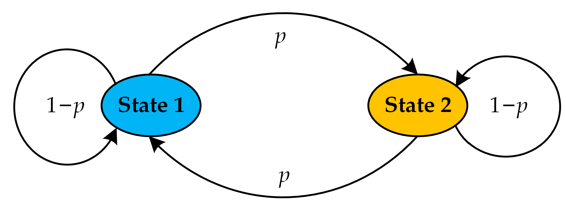
The control method of a permanent magnet synchronous motor based on a two-state Markov chain RPWM is implemented as shown in
Figure 6. Specifically, when the carrier frequency is greater than
fc, it is set as State 1; when it is less than
fc, it is set as State 2. When the carrier frequency is in State 1, the probability that the carrier frequency will be in State 2 in the next moment is
p, and the probability that it remains in State 1 is 1 −
p. When the carrier frequency is in State 2, the probability that it will be in State 1 in the next moment is
p, and the probability that it remains in State 2 is 1 −
p.
By analyzing and deriving the implementation method, the transition probability matrix of the RPWM based on the two-state Markov chain can be finally obtained with the following expression:
where
p11,
p12,
p21, and
p22 denote the probability of transferring from State 1 to State 1, State 1 to State 2, State 2 to State 1, and State 2 to State 2, respectively. In order not to affect the spectral characteristics of the system, the value of
p cannot be 1.
The results of the random numbers generated based on the two-state Markov chain are shown in
Figure 7. Compared with the random numbers in the traditional RPWM, the phenomenon that the random values in several consecutive cycles are greater than or less than the expected value is significantly reduced, the random number distribution is more uniform, and the carrier frequency distribution of the randomization is also better optimized.
3.3. Two-State Markov Chain Parameter Optimization Based on the Immune Algorithm
From Equation (8), the desired frequency and the random gain together determine the frequency variation range of the RPWM, so the random degree of the carrier frequency can be expressed as follows:
where
fmax and
fmin represent the upper limit of frequency change and the lower limit of frequency change, respectively.
It can be known from the above formula that the random degree is jointly determined by the random gain r and the desired frequency fc, while the value of fc is set in advance by the control requirements of the permanent magnet synchronous motor system. Therefore, the random degree is only determined by one parameter, random gain r, and the spreading effect depends on the size of the random degree, which means that r affects the final effect of the RPWM.
From this, it can be concluded that the magnitude of the values of the two spreading parameters, random gain r and transition probability p, play a decisive role in the final effect of the proposed method. Moreover, when the given range of these two parameters is large, the computation volume will increase as it is discrete data, which occupies a larger memory of the main control chip. Therefore, in this paper, the immune algorithm is chosen to optimize the spread spectrum parameters r and p so that the set of r and p with the best harmonic suppression effect can be found quickly.
The immune algorithm is an intelligent optimization algorithm inspired by the biological immune system, which has the characteristics of balanced global and local search, strong robustness, and anti-interference ability compared to other optimization algorithms (e.g., genetic algorithm, particle swarm algorithm, ant colony algorithm, etc.), which makes it more advantageous than other intelligent algorithms in solving parameter optimization problems [
25,
26].
When using the immune algorithm to optimize the parameters, the most critical link is to establish the evaluation target model. And through the above analysis, it can be known that each set of different values of
r and
p produces different harmonic suppression effects, which are manifested as different output current waveform spectra of permanent magnet synchronous motors in practical applications. The purpose of using the immune algorithm for parameter optimization is to find the minimum current spectrum harmonic peak within the given parameter range. This problem can be abstracted as the following expression:
where
f(
r,
p) represents the peak magnitude of the current spectrum harmonics of the experimental motor model under the set of independent variables
r and
p, and
y is the reciprocal of the peak magnitude of the harmonics. Thus, we have obtained the evaluation target model
y.
Now, the parameter optimization is converted into solving max(
y) with
r and
p, that is, using the immune algorithm to find the globally optimal solution, and the basic flow block diagram is shown in
Figure 8.
The global optimal solution is solved as follows:
Initial parameter calibration: According to the system parameters of the experimental motor, as shown in
Table 1, the parameters of the permanent magnet synchronous motor model in the simulation model are calibrated to ensure that the results of the simulation model are consistent with the experimental results;
Specification of the range of antibody values: The range of random gain r is set to [1500, 2500] and the range of transition probability p is set to [0.5, 1];
Initialization of antibody population: The initial antibody population A0 is randomly generated based on probability; each antibody in the population contains two basic information, that is, random gain r and transition probability p. Considering the small number of optimization parameters, the number of antibody populations is set to 30;
Calculation of the affinity of the antibody population: The antibody population is substituted into Equation (14) to obtain the evaluation target value, which is the affinity of the antibody population. From this, the affinity expression is obtained as follows:
where
n represents the number of iterations that have been performed by the immune algorithm,
an denotes the antibody at the nth iteration, and
aff(
n) signifies the affinity corresponding to the antibody
an;
Updating of the optimal solution affinity: During each iteration, each antibody is compared with the highest affinity antibody that has been generated, and a new global optimal solution is updated, hence the expression:
where
affmax and
affopt represent the antibody with the highest affinity and the globally optimal antibody affinity, respectively;
Determination whether the number of iteration steps is satisfied: The number of iteration steps is used as the termination condition; if the maximum number of iteration steps is satisfied, the optimization algorithm is stopped and the result is outputted; otherwise, the iteration is continued. The specific expression is
where
aopt denotes the global optimal antibody, representing the set of spreading parameters with the most optimal effect;
Algorithmout signifies the final output of the immune algorithm; Additionally,
N represents the maximum number of iteration steps, which is set to 50 to prevent the antibody population from converging prematurely or failing to converge due to excessive iterations;
Performance of immunological operations on the antibody population: A certain proportion of high-quality antibodies is selected based on affinity for cloning, and then mutation operations are performed on the cloned antibodies to generate a new antibody population. Subsequently, the mutated antibodies are screened and those with high affinity are retained. Among them, the expression for the cloning operation is
where
clone(
·) represents the cloning operation, which is a function used to generate cloned antibodies identical to the original antibody;
bn is the selected high-quality antibody, and
m is the number of cloned antibodies.
clone(
m,
bn) indicates generating
m cloned antibodies that are exactly the same as
bn, and these antibodies will form a set
C. The expression for the mutation operation is
where
cn represents an individual cloned antibody,
δ defines the range of neighborhoods, and
rand is a function that generates a random number within the range [0, 1]; The probability of mutation is denoted by
pm, and
D represents the antibody population subjected to the mutation operation;
Antibody population update: The antibody with high affinity obtained in the previous step is substituted for the antibody with low affinity in population An, thus generating a new generation of population An+1, and the new population is sent to step 4 to continue the iteration.
4. Experimental Results and Analysis
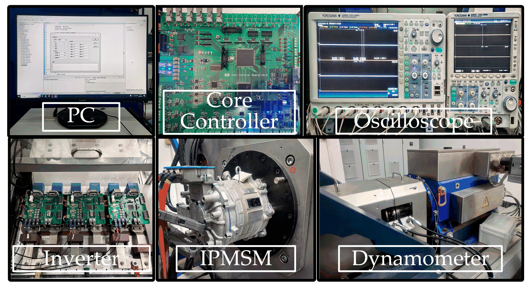
In order to verify the correctness of the theoretical analysis and the effectiveness of the proposed strategy, the experimental platform shown in
Figure 9 is built. The hardware circuit is built with TMS320F28335 DSP manufactured by Texas Instruments in Texas, the United as the core, and the speed/torque loading is realized based on the dynamometer driven by the AVL control system.
The experimental motor was operated under two steady-state conditions: at a speed of 3820 r/min, a load torque of 5 N·m, and a modulation index of 0.5; and at a speed of 3820 r/min, a load torque of 150 N·m, and a modulation index of 1.0. The traditional SVPWM, traditional RPWM, RPWM based on a two-state Markov chain, and the method proposed in this paper were experimentally verified. The expected carrier frequency fc is 10 kHz, the random gain r is 2 kHz, and the randomized carrier frequency fr varies randomly within the range of [8 kHz, 12 kHz].
In order to analyze the harmonic suppression effect of PMSM during operation, the experimental results are analyzed using frequency domain analysis, and due to the adoption of the RPWM, the Power Spectral Density (PSD) analysis method is further used.
4.1. Experimental Results of Conventional RPWM
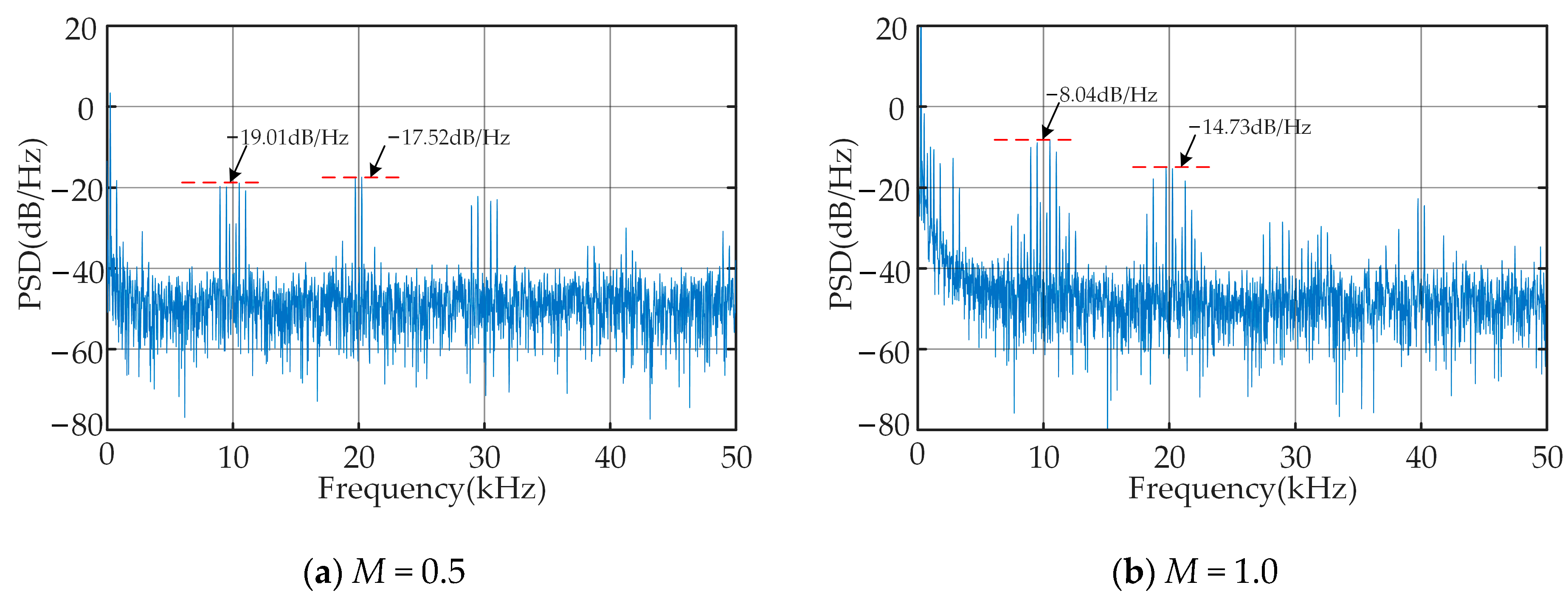
Figure 10 shows the current harmonic analysis of the conventional SVPWM. As can be seen from the figure, the harmonic energy generated by the traditional SVPWM shows a discrete distribution state throughout the entire frequency band, mainly concentrating at the integer multiples of the carrier frequency (10 kHz, 20 kHz, …). These harmonic components are the main sources of EMI. The harmonic energy after three times the carrier frequency has a significant attenuation, so this paper only considers the degree of amplitude decrease in the power spectral density near 10 kHz and 20 kHz. It can also be known from the figure that with the increase in the modulation index, the distribution characteristics of the power spectral density do not have an essential change, but due to the increase in the input energy of the motor system, the harmonic energy also increases, manifested as the increase in the amplitude of the power spectral density.
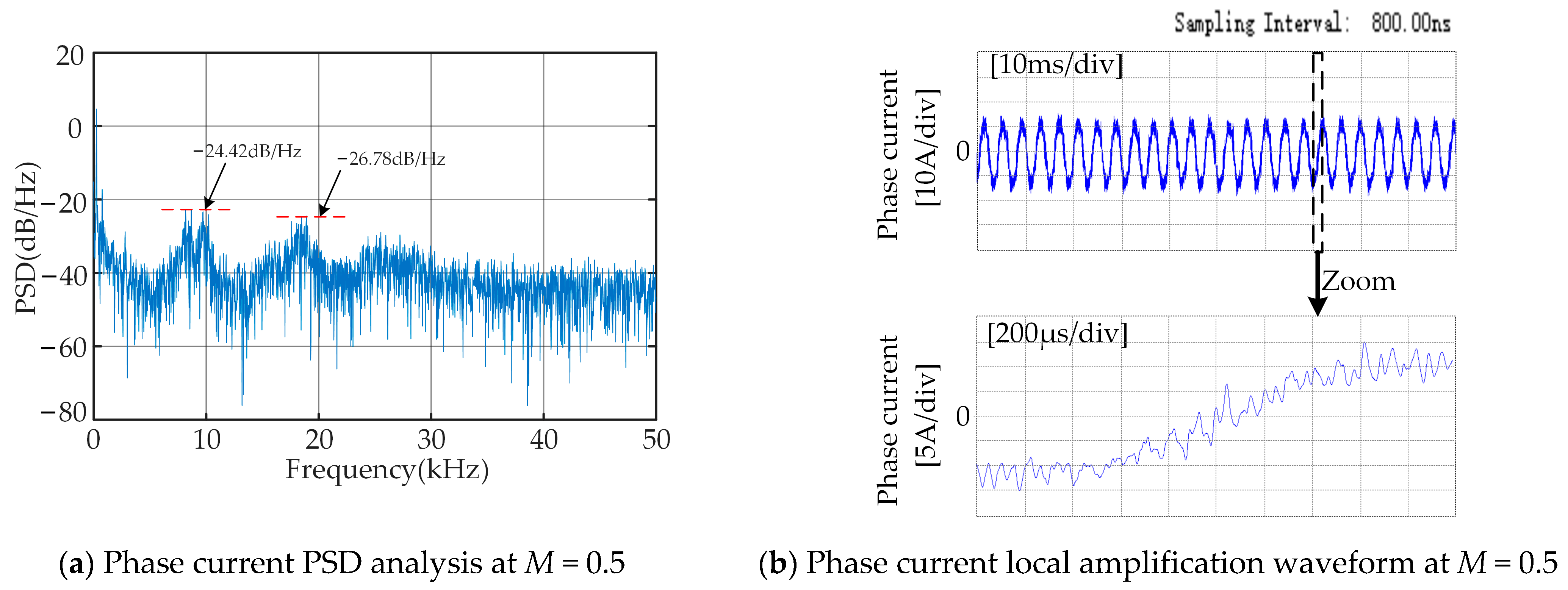
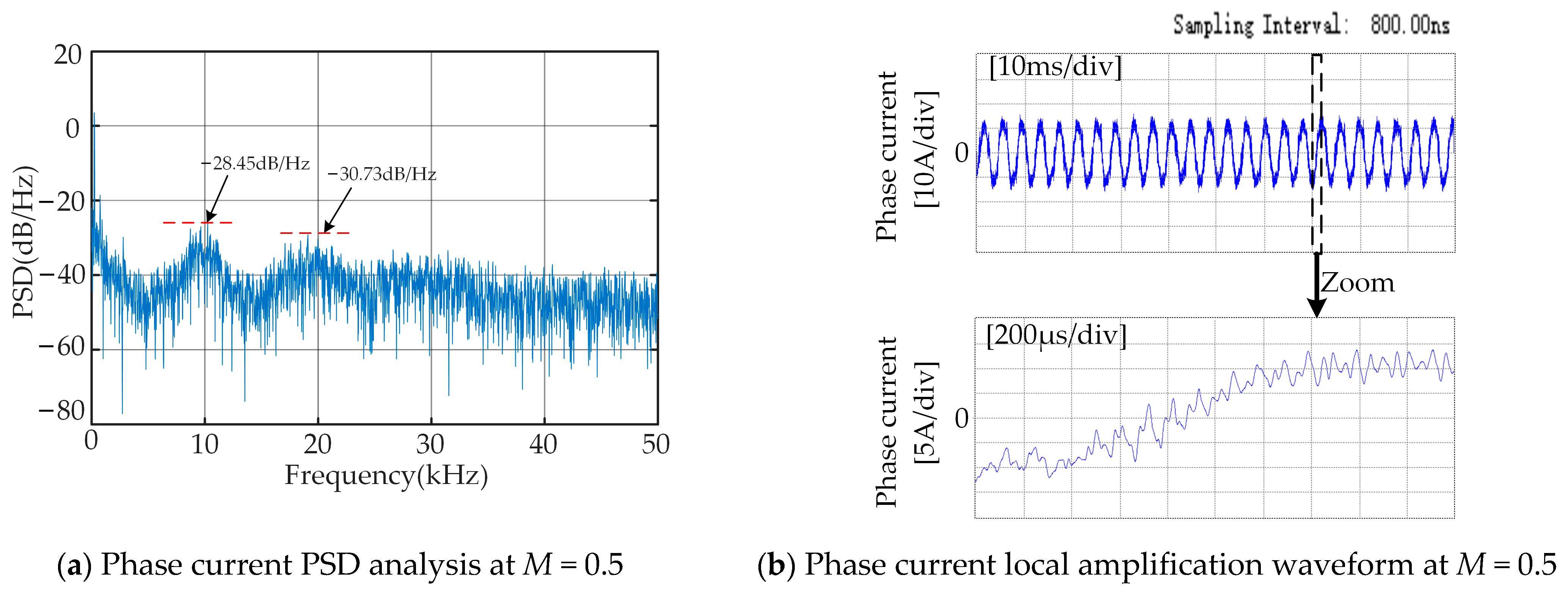
Figure 11 shows the current harmonic suppression effect of conventional RPWM. By comparing
Figure 11 with
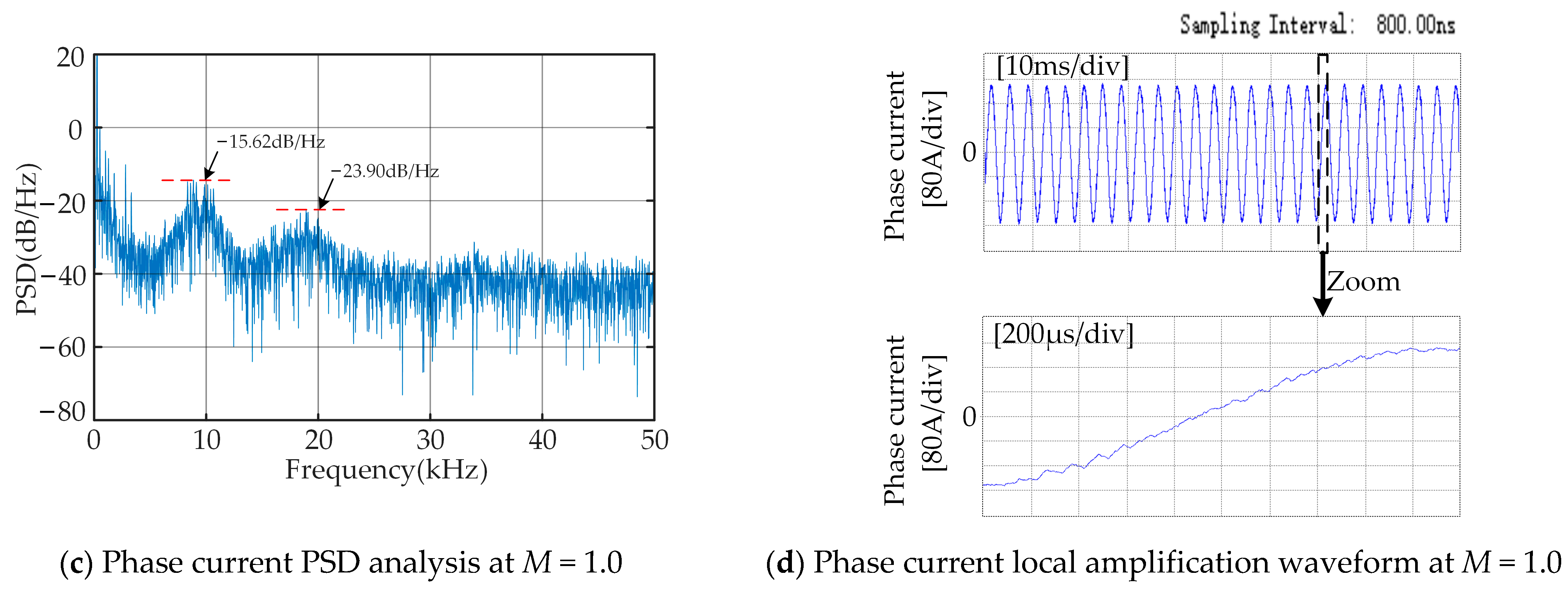
Figure 10, it can be seen that the traditional RPWM disperses the originally high-amplitude harmonic energy, making the distribution of harmonic energy more uniform. However, the suppression effect is limited, and obvious noise spikes still exist. At the power spectral density of 10 kHz and 20 kHz, when the modulation index is 0.5, they, respectively, decrease from −19.01 dB/Hz and −17.52 dB/Hz to −24.42 dB/Hz and −26.78 dB/Hz; when the modulation index is 1.0, they, respectively, decrease from −8.04 dB/Hz and −14.73 dB/Hz to −15.62 dB/Hz and −23.90 dB/Hz. At the same time, in the local current waveform, there will be several consecutive carrier cycles that are greater than or less than the expected carrier cycle, which is also consistent with the theoretical derivation.
By comparing
Figure 11b,d, it can be observed that as the modulation index increases (i.e., the gradually increasing torque of the motor load), the sinusoidal nature of the phase current waveform significantly improves, and the current distortion rate decreases accordingly. This phenomenon indicates that the motor system can operate in a more efficient condition when the modulation index increases.
4.2. Experimental Results of the RPWM Based on Two-State Markov Chain
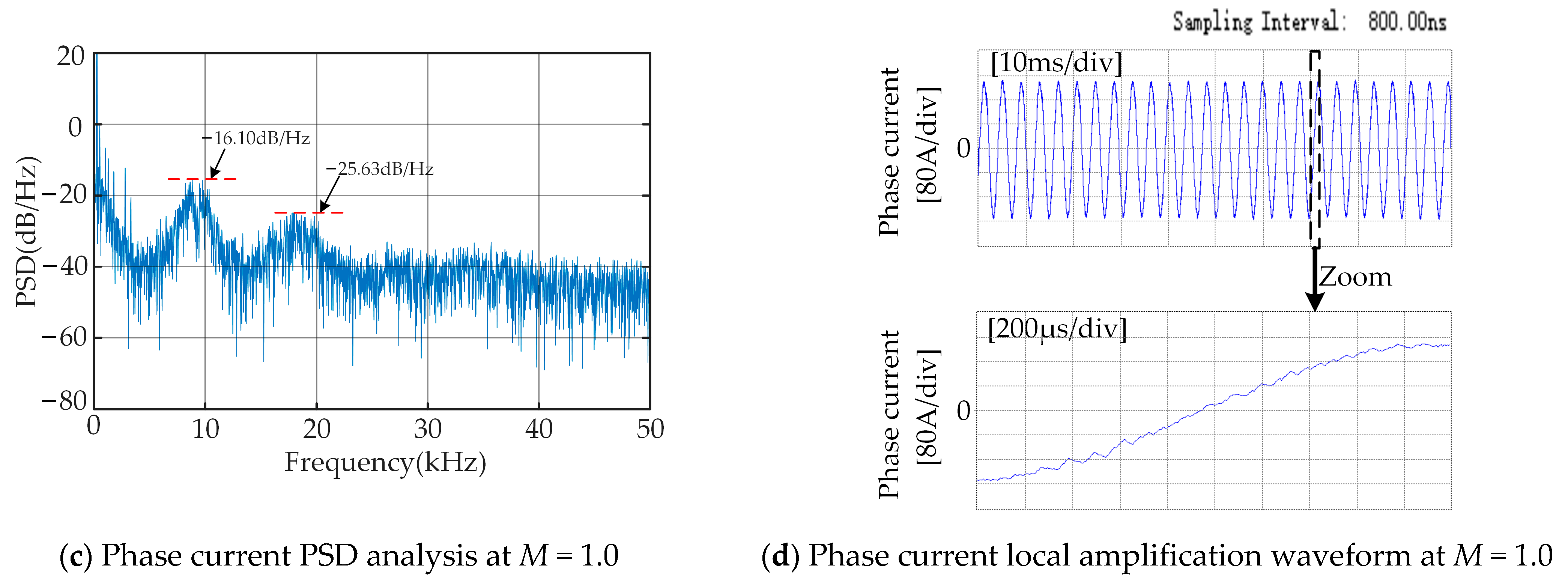
Figure 12 shows the current harmonic suppression effect of the RPWM based on a two-state Markov chain. By comparing
Figure 12 with
Figure 11, it can be seen that, compared with the traditional RPWM, the RPWM based on the two-state Markov chain further spreads the harmonic energy concentrated at the carrier frequency and its multiples and further reduces the amplitude of the harmonic energy. In the power spectral density near 10 kHz and 20 kHz, when the modulation index is 0.5, it drops from −24.42 dB/Hz and −26.78 dB/Hz to −27.29 dB/Hz and −28.89 dB/Hz, respectively; when the modulation index is 1.0, it drops from −15.62 dB/Hz and −23.90 dB/Hz to −16.10 dB/Hz and −25.63 dB/Hz. At the same time, the phenomenon of several carrier periods being greater than or less than the expected carrier period appearing in the local current waveform has decreased, and the quality of the current waveform has been improved.
In order to further optimize the random number generation results and enhance the spread spectrum effect, this paper conducts rapid optimization of two key spread spectrum parameters, r and p, based on the immune algorithm. When the peak value of the current harmonic is the minimum value, the optimal parameter combination is obtained. The optimal parameter group is then introduced into the RPWM based on the two-state Markov chain to improve the randomization of the carrier frequency distribution and further suppress the peak value of harmonic energy in order to achieve the optimal EMI suppression effect.
As shown in
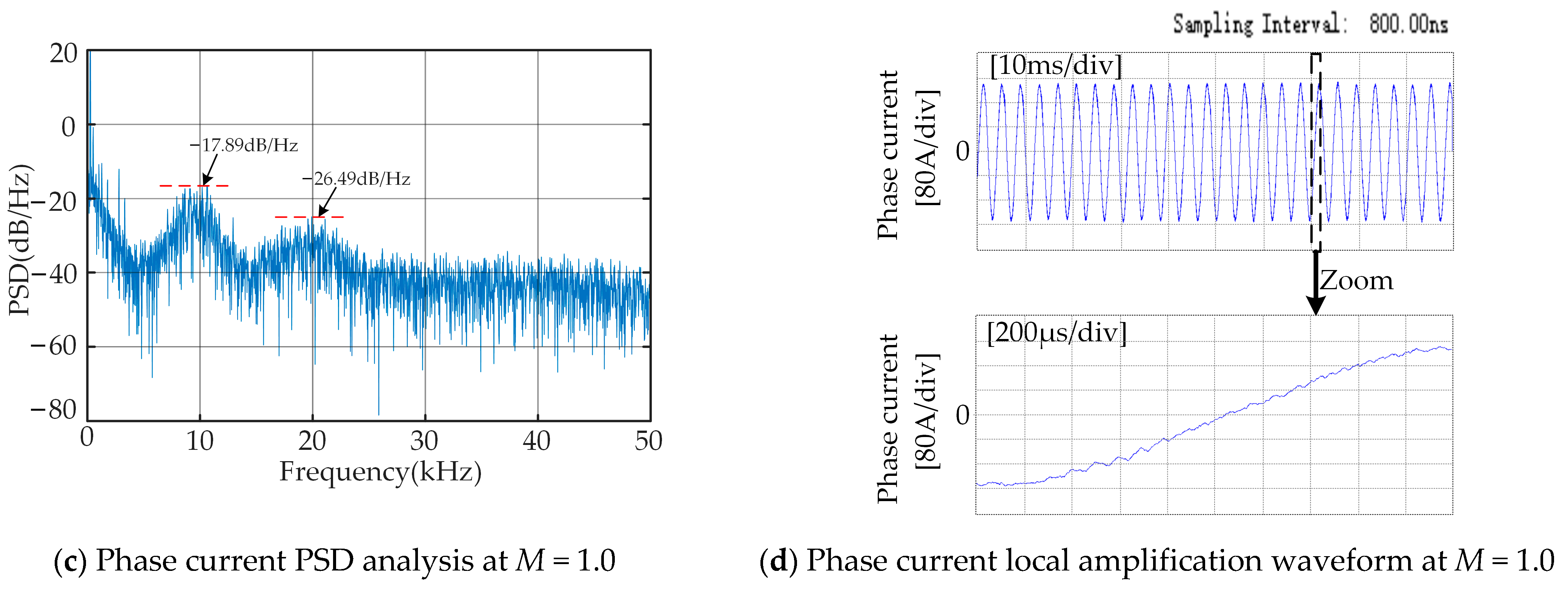
Figure 13, the current harmonic suppression effect based on the parameter optimization of the two-state Markov chain using the immune algorithm is presented. By comparing this method with the previous two RPWMs, it can be found that it performs better in terms of the power spectral density of the phase current and the current quality. The current frequency spectrum distribution is more uniform, the harmonic peaks in the power spectrum are significantly reduced, and the influence of EMI is further decreased. At the same time, from the local amplification waveform of the phase current, it can be seen that the phenomenon of being greater than or less than the expected carrier period for several consecutive carrier periods basically does not occur, and the current quality is maximally improved.
By combining
Table 2 and
Table 3, it can be seen from the power spectral density that compared with the traditional RPWM and the RPWM based on the two-state Markov chain, the two-state Markov chain parameter optimization method based on the immune algorithm has the best current harmonic suppression effect under different modulation indices.
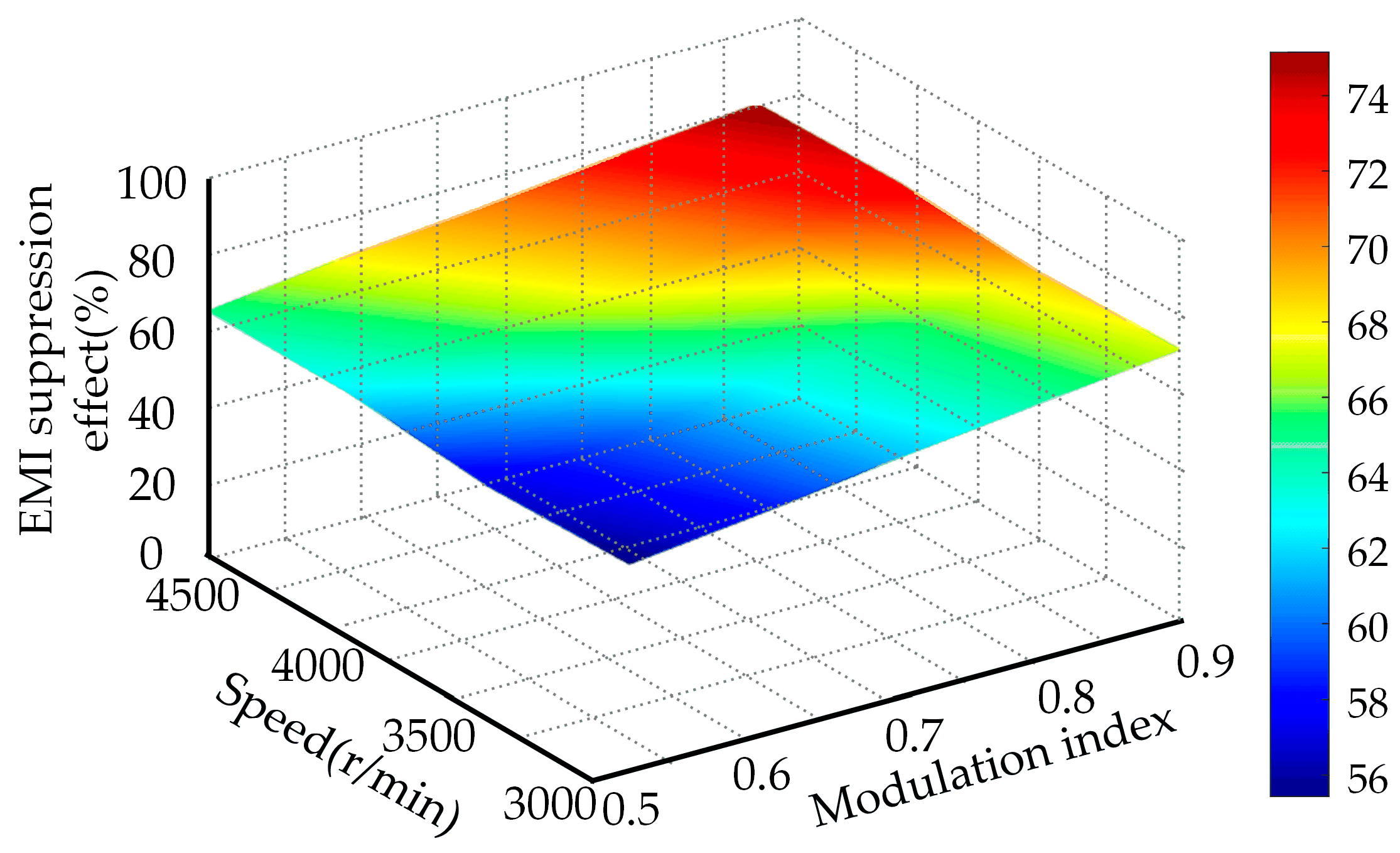
Figure 14 presents the EMI suppression effect of the two-state Markov chain parameter optimization method based on the immune algorithm under different rotational speeds and modulation indices. The EMI suppression effect is calculated as follows: the power spectral density amplitudes of the proposed method at 1 time and 2 times carrier frequencies are compared with those of the traditional SVPWM, and the obtained decrease amplitude (percentage quantity) is averaged to obtain the final result. The results show that the proposed method exhibits an excellent EMI suppression effect under different rotational speeds and modulation indices, with a more uniform spectral distribution and a significant decrease in the amplitude of high-frequency harmonics. This result further validates the effectiveness and applicability of the proposed method.


