Review

Review on the Recent Numerical Studies of Liquid Atomization

1
Chongqing Academy of Metrology and Quality Inspection, Chongqing 401123, China
2
Department of Energy and Power Engineering, Shandong University of Technology, Zibo 255000, China
*
Author to whom correspondence should be addressed.
Appl. Sci. 2025, 15(9), 4928; https://doi.org/10.3390/app15094928
Submission received: 19 March 2025 / Revised: 9 April 2025 / Accepted: 22 April 2025 / Published: 29 April 2025

Abstract

:

Featured Application

Liquid atomization has wide applications in jet-type and reciprocating engines, powder generation, cooling towers, and atmosphere dust removal.

Abstract

Liquid atomization has wide applications in jet-type and reciprocating engines, powder generation, cooling towers, and atmosphere dust removal. Droplet size and distribution are the decisive factors in the performance of the above applications. The rapid development and usage of computer science brings huge differences in the research manner of liquid atomization and has shed great light on the micro-phenomena of the formation, deformation, and rupture of liquid ligaments. However, the numerical methods of liquid atomization still lack efficiency due to their huge cost of computer resources and their accuracy due to their dependence on empirical correlations. Before achieving reliable implementation in atomization device design, such computational models must undergo rigorous validation against experimentally measured data acquired through advanced diagnostic techniques. The present paper reviews the mainstream numerical methods of liquid atomization including interface capturing, particle tracking, smoothed particle hydrodynamics, etc. Their respective numerical kernels and some representative simulation cases are summarized. The aim of the present review is to provide a general idea and future research orientation on the capabilities of modern computer and numerical models in calculating atomization and designing relative devices and hopefully guide future research to strive efficiently and productively.

1. Introduction

Atomization is the process of breaking down a liquid into fine droplets, thereby significantly increasing its surface area. This is achieved through mechanical, thermal, or aerodynamic forces, which disrupt the substance’s cohesive forces. The primary goal is to enhance efficiency in processes involving heat transfer, mass transfer, or chemical reactions by maximizing the surface area-to-volume ratio. Atomization enhances efficiency and precision across industries—from energy (fuel injection) and healthcare (nebulizers) to agriculture (pesticide sprays) and manufacturing (3D printing, spray drying).
Nozzles of various shapes are designed to generate spray of different liquids for the purposes of subsequent combustion, solidifying, or vaporization. Spray generation, or so-called liquid atomization, is a complex gas–liquid two-phase flow occurring in a very small space in a very rapid way, and it has wide applications in fields of fuel combustion, metal powder production, dust removal, cooling towers, and agriculture irrigation.
Although many efforts, such as the use of nuclear, wind, solar, or biomass, have been devoted to replacing fossil fuels in the past decades, massive exploitation and consumption of fossil fuels is still inevitable in the foreseeable future, as their stable supply and mature utilization technology are benefits. In the future, artificial liquid fuel—including biodiesel, alcohol, and ammonia energy—would be very promising substitutes for fossil fuel to overcome the crisis of energy shortage and pollutant emission. To convert the chemical energy contained in these liquids into mechanical power or direct heat, atomization and the subsequent combustion seems to be the unique way. However, under the great pressure of environmental protection, strict regulations on power equipment using liquid fuel have been enacted worldwide. L. Opfer [1] focuses on the spray atomization, transport, and impact on a solid substrate under cross-flow conditions, as used in airblast atomizers with prefilmers for aero engines and gas turbines. Computational fluid dynamics (CFD) has been used as a key element to understand and improve diesel spray [2]. The relevance of reference [3] is due to the necessity to intensify the secondary breakup of composite water-containing fuel droplets by their collisions with each other. Consequently, it can be said that liquid atomization plays a key role in energy fields as it determines the combustion efficiency and pollutant emission.
As an advanced machining technique, additive manufacture, or the so-called 3D-print, has become frequently used in the production of molds or sometimes structural components. Different from the PLA or ABS materials, which are commonly made into wire rode before being used in additive manufacturing, the metal materials are pre-processed into powders as the raw ingredient for metal additive manufacturing. One of the most popular ways is ejecting the liquid metal through a nozzle and atomizing it by aerodynamics forces [4]. The atomized metal droplets can then be cooled into solid ones rapidly with the help of the fast heat transfer with the ambient gas. This way of producing metal powders has the advantage of continuous high yield. However, the request for the uniformity of the resulted droplet size for use in additive manufacturing is much stricter than the other applications. A.M. Mullis [5] constructed a CFD model for gas flow within a gas atomizer, which is compared against high-speed video footage of a research scale atomizer. Computational fluid dynamic techniques were used to analyze the gas flow behavior [6], gas pressure [7], powder size considering phase change [8], and validation of a composite model [9] in a liquid metal atomization configuration. Therefore, one of the research focuses of metal powder production is controlling the powder size to be the predetermined value [5,6,7,8,9].
Both for the fuel ejection and powder production, liquid atomization finishes within a short distance of a few times of the nozzle diameter, after which vaporization or solidification occurs and gas–liquid flow disappears. Therefore, it is the primary and secondary breakup that play vital roles instead of the droplets’ collision and coalescence.
In order to suppress micro-particle contamination of the atmosphere as well as to reduce the incidence rate of respiratory disease, multi-stage breakup has been employed for cutting dust in the mining industry and sometimes in urban streets [10,11,12]. The size and distribution of the droplets and their interaction with the dust far from the nozzle exit determine the suppression efficiency and thus attract the most research focus. Other applications of liquid atomization that focus most on the spray far from the nozzle exit include spray systems to crop-dust or irrigate agriculture plants and cooling towers used for electricity production [13]. Droplets’ secondary breakup, collision, and coalescence are therefore important even in the far region from the nozzle, and their mechanisms must be taken care of when modeling this kind of liquid atomization.
Liquid atomization is one important type of gas–liquid multiphase flows. Different from internal gas–liquid flow, where a combination of two streams of particular speed usually corresponds to one flow pattern and thus all the macroscopic features like heat transfer and pressure drop can be evaluated [14], atomization shows varying patterns in a tiny space while having significant impact on the downstream spray evolution. Not only do the physical characteristics and flow speeds of the fluids influence the atomization pattern, but also the historical flow conditions, including the turbulence upstream and the nozzle shape, play a critical role. Description and division of the atomization regimes and mechanisms are still in development, and some controversial conclusions exist.
Predictions of shape of the spray as well as distributions of droplets size and velocity are also research objectives of liquid atomization. No matter what the liquid is (liquid metal or non-metal, combustible or not) and what kinds of nozzle, the micro phenomena the moment after the liquid is ejected out resemble each other. Also, the difficulties encountered when exploring these phenomena are also similar, such as the measurement of the dense region of the spray when trying to capture its high-resolution temporal and spatial evolvement. Fortunately, numerical simulation can act as a good substitute, possessing superiority over experimental observation in aspects of obtaining massive detailed temporal evolution of micro interface structure, although currently it requires huge computer resources unacceptable for practical use, in addition to the questionable accuracy of various models.
Numerical exploration provides measures to obtain details of the atomization that otherwise would be hard or impossible and helps to make certain serval atomization mechanisms. However, the current various numerical methods adopt inconsistent fundamental models and sometimes result in discrepancy among each other. Moreover, some methods cost huge computer resources, which is impossible for design purposes even within the foreseeable prosperous development of computer technology. The aim of the present review is to provide a general idea of the capabilities of modern computer technology and numerical models in aspects of simulating atomization and designing relative devices and to hopefully guide the future research to strive toward efficient and productive methods.
This paper is divided into eight sections. After this first introductory part, the general characteristics of liquid atomization including the different regimes for nozzle of various types are discussed in Section 2. Then, five main numerical frameworks including interface capturing, particle tracking, hybrid of interface capturing and particle tracking, multi-fluid and multi-scale Eulerian method, and smoothed particle hydrodynamics method are illustrated in sequence from Section 3 to Section 7, where their respective numerical kernels of primary and secondary breakup as well as some representative simulation cases are summarized. The possible subsequent evaporation, combustion, or solidification will not be considered, since this paper focuses on the atomization itself. Finally, the future research focus and orientation are suggested in Section 8.

2. General Overview of Liquid Atomization

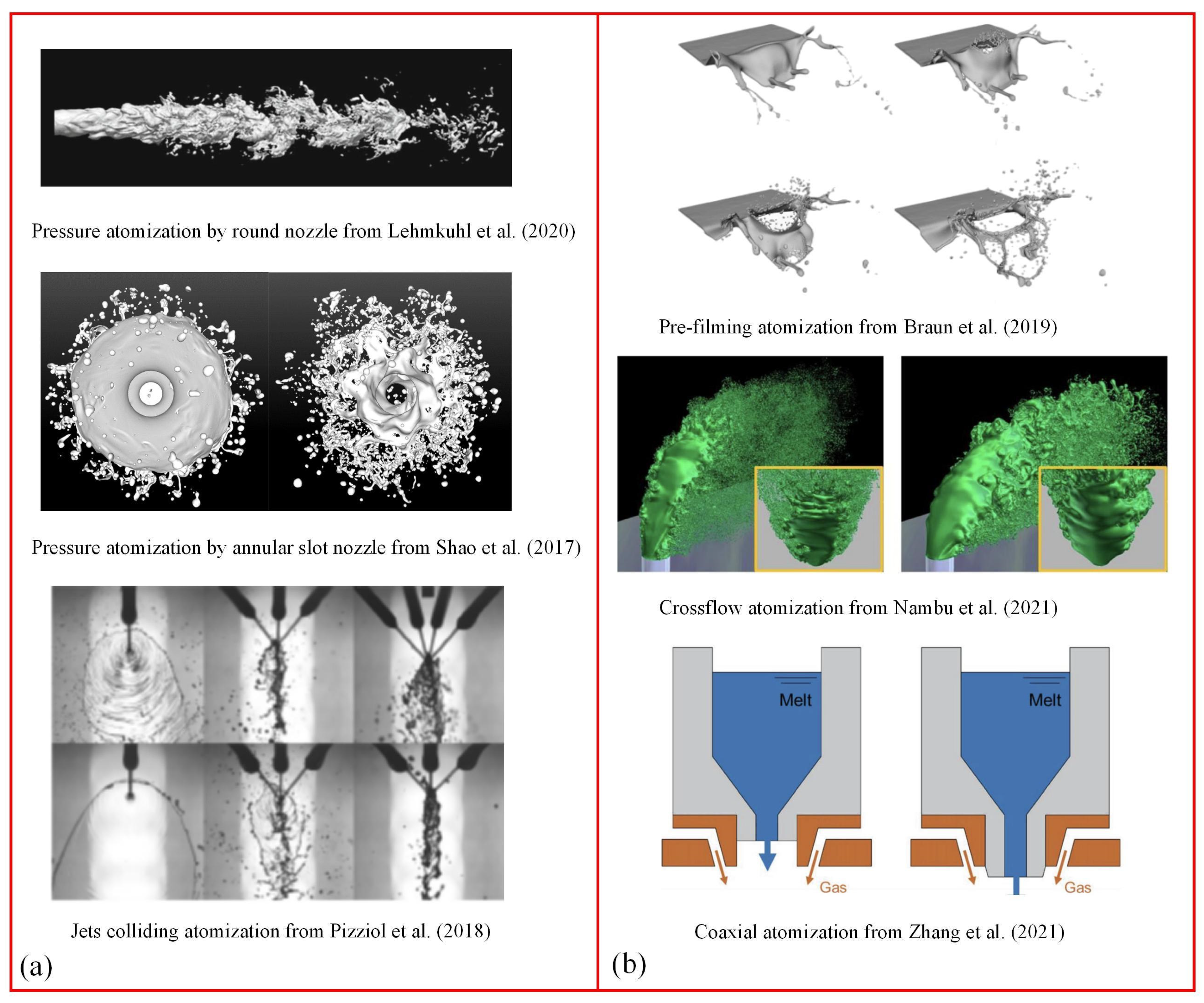
2.1. Atomization Types

As shown in Figure 1, liquids can be atomized through different layouts of nozzles and external gas streams. The spray formed by single-phase liquids ejecting into stationary atmosphere is classified as non-gas-assisted, since the first factor leading to primary breakup is the internal turbulence and the external gas has weak influence [15]. The ejection speed and turbulence stem from the great pressure difference between inside and outside the nozzle, so the non-gas-assisted atomization is usually called pressure atomization [16]. Nozzles of round shape and slot are commonly adopted, and pressure swirl nozzles into which a swirl structure is built help expand the spray angle and generate finer droplets [17]. Several liquid streams colliding with each other rapidly can also lead to atomization, called impact atomization [18]. One advantage of non-gas-assisted atomization is the free mixing ratio of gas and liquid. While colliding jets effectively induce interfacial instabilities through momentum exchange, recent studies demonstrate that pulsating injection can further enhance atomization efficiency by modulating vortex formation. Periodic flow oscillations amplify Kelvin–Helmholtz instabilities at the gas–liquid interface, reducing critical Weber numbers for droplet detachment by 15–30% [19]. This mechanism promotes finer sprays (<50 μm SMD) while suppressing satellite droplet formation, as evidenced by time-resolved PIV measurements in intermittent jets [20]. Such pulsation-driven effects warrant consideration alongside geometric nozzle optimization in next-generation atomizer designs.
For gas-assisted atomization [26], gas is conveyed compulsively to intervene with the liquid either inside or outside the nozzle, and the aerodynamic forces become the first factor leading to primary breakup. Crossflow atomization [27] is usually adopted in jet engines, where the air usually flows at high-speed vertical to the fuel ejection direction. Coaxial atomization [28] is one kind of parallel-flow atomization when the liquid is ejected through a hole in the center of nozzle, while the high-speed gas is ejected through the toroidal slot around the nozzle. Sometime there could be an angle between the path of the liquid and gas instead of parallel, so the gas impacts somewhere downstream of the liquid exit and stimulates the breakup. Coaxial atomization is often encountered in powder production from liquid metal.
Pre-filming atomization [29] is being investigated for use in lean burn combustors to further promote fuel efficiency and low pollution. The liquid film is pre-distributed on a plane through conceal holes or wall jet and the high-speed gas is blowing from both up and down sides of the plane. The instabilities between the gas and liquid grow before the plane edge after which the atomization starts from the primary breakup of the liquid film.

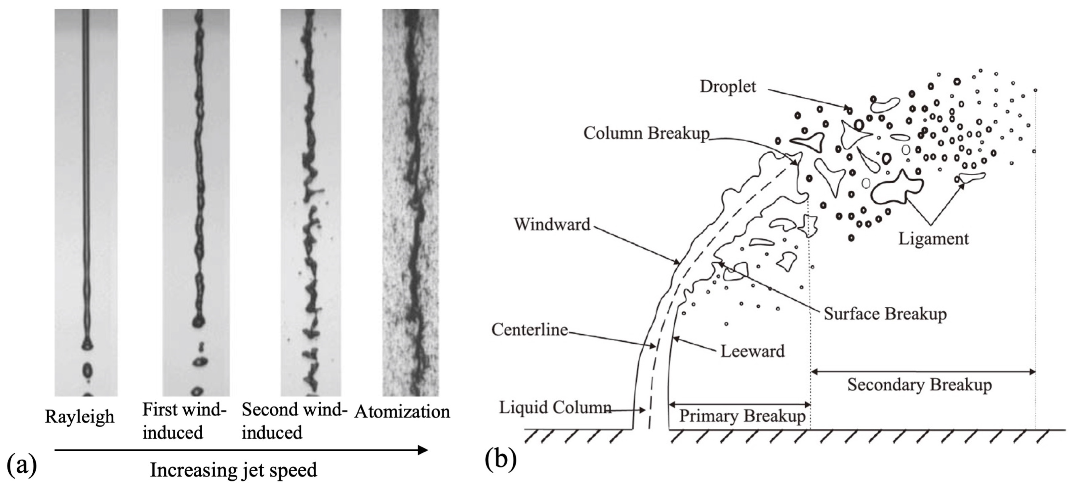
2.2. Two Atomization Regions

In this paper, the nomenclature regime is used to describe one particular atomization pattern and region is used to distinguish patterns at different locations. Spatially, the atomization in the vicinity of the nozzle exit is called primary breakup. The broken-up liquid ligaments in this stage can be ellipse, strip, membrane, bag, et al. At some distance, some of these ligaments would experience secondary breakup into finer droplets.

2.2.1. Primary Breakup

Under different combinations of fluids properties and flow speeds, primary atomization would demonstrate clear visual distinction, forming the so-called different atomization regimes. The essential reasons resulting in these various atomization phenomena are the variation of the importance of different forces, such as the inertia force, surface tension force, and viscous force. For different layouts of nozzles, the regimes that can be exhibited with the increase of flow speed also change.
For round jets that are not gas-assisted, dripping regime, Rayleigh regime, first wind-induced regime, second wind-induced regime, and atomization regime appear in sequence with the increase of the liquid speed, as shown by Figure 2a. For round jets with coaxial gas-assisted, three atomization regimes can be identified as Rayleigh-type breakup, membrane-type breakup, and fiber-type breakup with the increase of relative speed between phases. Dumouchel [30] reviewed the experimental investigations on confirming these regimes and exploring the underlying mechanisms. His review covered round jets, slot sheets, air-assisted round jets, and air-assisted slot sheets. The varying competing factors including turbulence energy, Rayleigh-Taylor (RT) instability, and Kelvin–Helmholtz (KH) instability contribute to the regime transitions.
For crossflow atomization in Figure 2b, the jet is curved towards the gas flow direction by aerodynamic forces. At low gas speed, the liquid jet only breaks up at the end of the column, called column breakup. The column breakup resembles droplet breakup and can show bag mode, multimode, sheet-thinning mode, shear mode, and catastrophic mode. As the gas speed increases to some extent, surface breakup occurs due to the KH instability. Detailed reviews on the cross-flow atomization can be found in works of Wu et al. [32] and Mashayek and Ashgriz [33].

2.2.2. Secondary Breakup

Ligaments disintegrated from the continuous liquid jet or film may encounter further breakup depending on the relative magnitude of surface tension force, aerodynamic force, and viscous force. It is worth nothing the droplets formed from the secondary breakup may break a third and fourth time and they are still classified as a secondary breakup.
A massive review on secondary atomization has been presented by Guildenbecher et al. [34], where abundant literature on experimental methods, breakup regime, timing, droplet size and velocity distributions are discussed. Generally, the breakup regime is controlled by the relative speed between gas and droplet, or by the non-dimensional Weber number We. Also, there exists a critical We around 11, below which the breakup is suppressed by the surface tension. As the We increases from the critical value, vibration mode, bag breakup, sheet-thinning breakup, multimode, and catastrophic mode can be observed in order. The liquid viscosity, which is measured as the ratio of viscous force to surface tension force (Oh), shows a minor effect on the breakup morphology unless Oh increases to more than unit, which is not common for regular liquid. The secondary atomization regimes are schematically shown in Figure 3.

2.3. Non-Dimensional Groups

The breakup patterns in a spray can be highly complicated due to multiple entities, re-entrant, and other topologically complex interfaces, plus multiple spatial and time scales. In addition, multiple physical properties and fluid properties influence liquid atomization, which makes mathematical and numerical description very challenging, especially in the early days of this field. Fortunately, predecessors described their findings in terms of a number of non-dimensional groups. They are still in use today, and most authors make use of one or more of those listed in Table 1. The logic behind their choice is as follows.
No matter in primary or secondary atomization, the aerodynamic forces act to deform a liquid surface, causing it to become unstable or fragment. This deformation is resisted by the surface tension force, which tends to restore the surface to be flattened and smooth. As a result, the Weber number, We, defined as the ratio of the disrupting aerodynamic forces to the restorative surface tension force, is the most important parameter when describing atomization. The We can be defined as the gas We using gas properties, liquid We using liquid properties, or relative We using the relative velocity between phases. A larger We indicates a higher tendency toward fragmentation.
Viscosity hinders deformation and also dissipates kinetic energy supplied by aerodynamic forces. Both factors reduce the likelihood of fragmentation. To account for this, many authors make use of the Ohnesorge number, Oh, which represents the ratio of viscous force to surface tension force. A higher Oh indicates a lower tendency toward fragmentation. The Ohnesorge number is usually defined using the properties of liquid phase.
Other important dimensionless groups are the density ratio of liquid to gas ε, the viscosity ratio of liquid to gas N and the Reynolds number, which is not independent because it can be derived from We and Oh. The momentum flux ratio of the liquid to gas q is an indicator of the jet trajectory and how far the liquid jet can penetrate into the atmosphere.
These dimensionless groups are not only related to the atomization regimes but also influence the choice of numerical methods. Their definitions are summarized in Table 1.

3. Interface Capturing

The interface capturing methods try to locate the interface shape and position at each numerical iteration step based on the volume fraction or signed distance function, depending on if volume of fluid (VOF) or level set (LS) method is used, which are representatives of interface capturing methods. The VOF method is able to guarantee the conservation in nature but requires more computation cost when calculating the normal interface and curvature. The LS makes up this disadvantage but loses in conservation nature. Therefore, they are frequently coupled together in liquid atomization called the CLSVOF method. The smoothed particle hydrodynamics (SPH) method and lattice Boltzmann method (LBM), which are going to be discussed in following sections, also have the ability to capture interface, so in some literature [35] they are also referred to as the interface capture method.

3.1. Mathematical Description

As a single-fluid Eulerian method, the gas and liquid phases in VOF and LS share the same conservation equations, which are shown as follows:
ρ t + · ρ U = 0
( ρ U ) t + · ρ U × U = P + · T + ρ g + F σ
( ρ e ) t + · ρ U ( e + P ρ ) = · q + · ( T · U ) + κ σ α · U
where U is velocity, α is the volume fraction of the liquid phase, ρ is density, P is pressure, σ is the surface tension coefficient, κ is the local interface curvature, e is the total energy per unit mass, g is gravity, T is the viscous stress tensor, which can be obtained from Newton internal friction law, q is the heat flux vector, which can be obtained from Fourier’s law, and Fσ is the surface tension force, which can be calculated using the continuous surface force (CSF) method as follows [36]:
F σ = κ σ n
where n is the interfacial normal vector. The interface normal vector and curvature are calculated as:
n = α ,   a n d   κ = · n
As a single set of N-S equations are employed for two fluids, the properties including density, thermal conductivity and viscosity must be replaced by fraction-weighted or mass-weighted average value.
In the VOF method, volume fraction of 1 and 0 represent liquid and gas phases, respectively, while intermediate values represent the interface. The tracking of the interfaces is accomplished by the solution of a continuity equation for the volume fraction of secondary (liquid) phase, as shown in Equation (6), and the volume fraction of primary (gas) phase can be taken as 1-α.
α ρ l t + · α ρ l U l = 0
In the LS method, the interface is represented by the zero value of a level set function φ(x, t) [37], which equals the signed distance d to the nearest interface location. The evolution of φ can be expressed similar to the volume fraction:
φ t + · φ U l = 0
The momentum equation is the same with Equation (2), and the surface tension force can be given by:
F σ = κ σ δ ( φ ) n
where δ(φ), n, and κ can be expressed by:
δ φ =   0 ,                                           φ > a   1 + cos ( π φ a ) 2 a ,   φ < a
n = φ φ ,   a n d   κ = · n
With the transportation of the level-set function by Equation (7), the features of it representing distance from the interface cannot be guaranteed due to the deformation of the interface and uneven profile. To avoid the errors from accumulating in mass and momentum solutions, at each time step the level set function is re-initialized as a distance function; that is to guarantee |∇φ| = 1. Due to the reinitialization, the LS method is found to have a deficiency in preserving volume conservation. One of the reinitialization methods to improve the conservation is to couple with the VOF by using the interface-front construction method through the use of both values of VOF and LS function. More details of the different reinitialization methods can be found in Luo et al. [35].

3.2. Application Cases

Warncke et al. [38] combined direct numerical simulation (DNS) and large eddy simulation (LES) turbulence model, respectively, in the dense and sparse regions of a pre-filming atomization. A total number of 84 million cells were used with a time step of 5 × 10⁻⁸ s. VOF in the OpenFOAM was employed, resulting in comparable gas–liquid patterns and droplet distribution with the visual measurement. Huang and Zhao [39] considered evaporation in their simulation of liquid fuel jet. In their VOF method, ghost fluid method (GFM) was used to solve the discretizing problem of the jumping interface, and 130 million cells were created in a region of 4 mm × 4 mm × 16 mm.
Hanthanan et al. [40] studied the influence of gas pressure on the droplet size distribution of metal powder production. The instantaneous and local complexity of the gas–liquid interface was captured using the VOF method integrated in the OpenFOAM, and a clear increment of the atomization effectiveness was found with the increasing gas pressure. The LES model was adopted to capture the turbulence vortex. In order to keep track of both primary and secondary breakup, a quarter cylindrical domain with radius and length of 20 mm and 100 mm, respectively, was simulated. Due to the demand of Courant number with a gas velocity more than 1500 m/s, 11.8 million cells as well as a time step of 10−8 s had to be used.
Ketterl et al. [41] analyzed the unclosed terms stemming from filtering of the two-phase flow LES equations, which have not been fully covered in the single phase LES method. An idealized jet imitating diesel injection with both density ratio and viscosity ratios equal to 40 has been simulated with the VOF method in the PARIS solver. As no experimental results were available, the LES results were verified in comparison with the DNS results. In a cuboid region in the dimension of 10 mm, 2 million cells were adopted in the LES method and 900 million cells for the DNS method. The studied sub-grid scale (SGS) closure models include convective term, surface tension term, Favre filtered velocity divergence and flux in the interface advection equation. They showed the closures for each unknown term strongly interact with the other terms and as well with the numerical scheme.
Lehmkuhl et al. [21] used an entropy stable conservative method to overcome the inefficiencies of the LS method. The comparison of LES results with DNS reference data indicated a good agreement in aspects of interface concentration and void fraction. Liquid jet into moderate gas pressure was used in their simulation, and only an atomization duration of 45 μs was calculated with 60 million cells.
Mingalev et al. [42] simulated the air-assisted pre-filming atomizer of kerosene. The VOF in commercial software Fluent 2021 R1 was used along with the DNS turbulence model. They focused on the different droplet size distributions between 2D and 3D simulation. The VOF from Fluent was also adopted by Hua et al. [43] to investigate the effect of wall roughness on atomization of diesel injected from a hole of 0.1 mm. Only a realizable k-ε turbulence model was used since they focused on the injection angle and penetration length. Mantripragada et al. [8] cooperated the heat transfer and solidification models into the VOF of Fluent to predict the droplet size distribution formed from a centrifugal atomizer, and the turbulence was accounted for by the SST k-ω model.
The atomization during coughing and sneezing resembles that of air-assisted pre-filming atomization and has gained major concern during the COVID pandemic. Pairetti et al. [44] performed one expensive DNS simulation using the VOF method. In a region of 50 mm × 20 mm × 10 mm, 500 billion cells have to be created, so as to resolve the Kolmogorov turbulence scale. A total of 3.2 billion cells were found enough with the assist of adaptive mesh refinement method (AMR), though a refinement level between eleven to thirteen has to be employed, which is also a huge computer burden.
With their inhouse numerical code ARCHER, Asuri et al. [45] performed a simulation on pre-filming atomization with the CLSVOF method and synthetic turbulence model. A total of 3.3 million grids were created in a zone with a scale of 6 mm. The simulation results showed agreement with the experiment of Gepperth et al. [46] qualitatively in ligament formation process, but under-predicted the formation frequency.
With the CLSVOF method and LES model, Chang et al. [47] calculated the jet atomization in a crossflow within a rectangular channel of length, width, and height of 55D × 30D × 30D, where D is the nozzle diameter. Subsonic air speed of 180 m/s was used to mimic a combustion situation in a cruising airplane. A total of 3.4 million primary cells were created, which was adaptive to 8.6 million during calculation with an AMR level of three. The trajectory of the jet was comparable to an experimental observation, and they also demonstrated the KH instability and RT instability dominate the breakup in the downside and upside of the liquid column, respectively.
Table 2 compares the commonly used mathematical modeling methods mentioned above. It can be seen from the above review that LES or DNS are usually adopted as the turbulence model in order to fully resolve the gas–liquid interface in atomization. This is because the interfaces evolve very rapidly in scales as small as the turbulence vortices, and the Reynolds-averaged Navier–Stokes (RANS) turbulence models only resulting in time-average information are not competent. However, LES or DNS would require grid numbers in the magnitude of hundreds of millions or billions within just a calculation zone of a few millimeters. This unbearable burden even for most supercomputer centers indicates impossibility for engineering design purposes.

3.3. Summary

Liquid atomization modeling faces three critical challenges in interface-capturing methods: (1) numerical dissipation during microscale interface evolution, addressed through CLSVOF with Gaussian curvature correction and THINC/QQ algorithms, reducing droplet volume errors to <1% while maintaining 2–3 cell interface sharpness; (2) high Weber number oscillations mitigated by tensor-based CSS formulations and IMEX-BDF2 temporal schemes, achieving 68% velocity fluctuation suppression and CFL stability enhancement to 0.5; (3) multiphysics computational bottlenecks overcome via DRL-AMR and transformer-accelerated models, delivering 8–100× speedups validated on 100 M-grid aerospace atomizers. Emerging quantum-AI hybrid paradigms and digital twin frameworks (EU H2020 AMPHIBIAN case) demonstrate potential for 1000× efficiency gains and <5% cross-scale errors, positioning these solutions as foundational for next-generation atomization design across energy and propulsion systems.

4. Particle Tracking

Considering the current computer technology, particle tracking is more suitable than interface capturing in aspects of simulating the full primary and secondary atomization regions covering a broader space. Droplets having the same properties are tracked in a Lagrangian manner in a liquid parcel thus saving computer resources. However, the breakup mechanisms of continuous liquid jet or disintegrated ligaments must be accounted for by semi-empirical correlations. A dedicated review back in 2011 on the different breakup models can be seen in Chryssakis et al. [48].

4.1. Mathematical Description

The motion of the gas phase is still in the Eulerian framework, while the particle motion is solved by the integral of Newton’s law, which can be written as:
m p d u p d t = F d + F g + F x
where mp is the parcel mass, up is the velocity, Fd the drag force, Fg the gravitational force, and Fx represents the other force and are usually neglected. For instance, the magnitudes of the longitudinal forces such as Basset force, pressure gradient force, and virtual mass force are at least two orders less than the drag force. The Magnus force acting on rotating spheres and lift force working on high tangential zone are also not the case for the parcels in atomization flow field and thus can be ignored. The drag force can be expressed by:
F d = 1 2 C d A p ρ ( u u p ) u u p
where Cd is the drag coefficient and Ap is the windward area.
The Lagrangian tracking framework resolves droplet trajectories at the resolved scale (>50 μm) yet cannot intrinsically capture sub-particle interfacial instabilities that govern breakup processes. This necessitates the introduction of breakup models to close the momentum exchange term, where the droplet acceleration is modulated by competing forces.
d u d d t = u g u d τ d D r a g + C W e σ ρ d r d 2 n S u r f a c e   t e n s i o n + B ( W e , O h , η ^ ) B r e a k u p i n d u c e d   a c c e l e r a t i o n
Here, the breakup term B is parameterized through the Taylor analogy breakup (TAB) or Kelvin–Helmholtz/Rayleigh–Taylor (KH-RT) models, which inject SGS interface instability effects into resolved-scale motion via: Weber number (dictates droplet deformation thresholds), Ohnesorge number (controls viscosity-dominated breakup delay), axis-switching parameter (tracks preferential breakup orientations from local shear spectra). This multiscale coupling enables particle tracking methods to reproduce experimentally observed spray granulometry within 12% error.
Turbulence models of RANS, LES, and DNS are all competent for particle tracking method. Since particle tracking usually covers a much wider range of atomization than interface tracking, RANS models are more often used as it saves computer resources.

4.2. Breakup Models

Breakup models are generally accepted as one of the largest sources of uncertainty in a CFD simulation of atomization. Shown below are fundamental ones, based upon which more sophisticated models have been proposed.

4.2.1. Huh-Gosman Model

One commonly used primary breakup model was developed by Huh and Gosman (HG) [49]. It assumes the length scale of turbulence originating from upstream overwhelms the wavelength of surface perturbations. The breakup length scale LHG (length scale in the Huh–Gosman model) and time scale τHG (time scale in the Huh–Gosman model) can be expressed by:
L H G = C 1 L T = C 2 L w
τ H G = C 3 τ T + C 4 τ W
where C1, C2, C3, and C4 are empirical model constants set as 2, 0.5, 1.2, and 0.5. LT, LW, and τT, τw, respectively, represents the length scale and time scale of turbulence and surface wavelength, and their values can be obtained from:
L T = L T 0 ( 1 + C a 1 t τ T 0 ) C a 2
τ T = τ T 0 ( 1 + C a 1 t τ T 0 )
τ W = L w U ρ l ρ g
where Ca1 and Ca2 are usually taken values around 0.9 and 0.45, respectively. U is the relative velocity between phases. LT0 and τT0 are the initial turbulence length and time scale determined from the turbulence energy and dissipation rates at the nozzle exit.
The liquid jet can be represented in the form of computational parcels, with the rate of change of parent droplet size proportional to the ratio of breakup length over time scale:
d a d t = L H G τ H G
A new parcel is created once its mass exceeds 10% of the initial mass of the parent parcel, and the size of parent parcel is adjusted according to Equation (19) while the size of the child parcel is set to LHG.

4.2.2. Wu-Faeth Model

The Wu–Faeth (WF) model [32,50] also adopts the breakup length and time scales to characterize the primary breakup, which can be expressed respectively by:
L W F = C s x Λ ( x   Λ W e l Λ 0.54 ) 0.57
τ W F = ( ρ l L W F 3 σ ) 1 / 2  
where Λ is the radial turbulent integral length scale equal to d/8, x is the distance from the nozzle exit, and Csx is the model constant with recommended value of 0.65. The radius of the parent droplet changes according to:
d a d t = C W F L W F τ W F
where CWF is recommended to be 0.7.

4.2.3. Taylor Analogy Breakup Model

The Taylor analogy breakup (TAB) model is suitable for the low-Weber-number droplet. This method is based upon analogy [51,52] between a distorting droplet and a spring mass system, assuming the droplet is only undergoing oscillation mode. The breakup occurs for y > 1, where y is obtained from:
d 2 y d t 2 = C F C b ρ g ρ l u 2 r 2 C k σ ρ l r 3 y C d μ l ρ l r 2 d y d t
where Cb, CF, Ck, and Cd equals to 0.5, 1/3, 8, and 5, respectively. u is the relative velocity between gas and droplet and r is the undisturbed equivalent radius of the parent parcel. The Sauter mean radius of the child droplets can be found by:
r 32 = r 1 + 8 K y 2 20 + ρ l r 3 d y d t 2 σ ( 6 K 5 120 )
where K is the ratio of the total energy in distortion and oscillation to the energy in the fundamental mode and can take the value of 10/3. The diameters of the resulted child droplets obey the Rosin–Rammler distribution with the r32 from Equation (24) and spread parameter of 3.5.

4.2.4. Kelvin–Helmholtz Model

The Kelvin–Helmholtz (KH) model is suitable for droplet Weber number greater than 100 [53]. The radius of the newly formed droplets is proportional to the wavelength Λ of the fastest-growing unstable surface wave on the parent droplet, given by:
r = B 0 Λ
where B0 is a constant equal to 0.61. The rate of change of droplet radius a in the parent parcel is given by:
d a d t = ( a r ) τ
and τ is:
τ = 3.726 B 1 a Λ Ω
where B1 is an empirical breakup time constant in the range between 1 and 60. The maximum growth rate of the surface wave ΩKH and its corresponding wavelength ΛKH were deducted by Reitz [53] by numerically analyzing the KH instability and can be expressed as:
Λ K H a = 9.02 ( 1 + 0.45 O h 0.5 ) ( 1 + 0.4 T a 0.7 ) ( 1 + 0.87 W e 2 1.67 ) 0.6
Ω K H ρ 1 a 3 σ = 0.34 + 0.38 W e 2 1.5 ( 1 + O h ) ( 1 + 1.4 T a 0.6 )
where the dimensionless groups have been defined in Table 1.

4.2.5. Rayleigh–Taylor Model

The KH-RT breakup model was meant for high We and low-pressure systems. Generally, it divides the dominant mechanisms to be KH instability within the liquid core and RT instability outside. The length of the liquid core L is defined as [54]:
L = C L d 0 ρ l ρ g
where CL is the Levich constant and d0 is a reference diameter. For conical injections, d0 is the minimum of the droplet diameter and the inner diameter of the nozzle. For surface injection from a droplet, the equivalent hydraulic diameter of the surface area is used as d0. For droplets distributed in a Rosin–Rammler manner, the maximum diameter of the Rosin–Rammler becomes the d0. The liquid core just outside a nozzle is the continuous liquid jet, which can be regarded as consisting of a series of blobs, so this breakup model also applies to primary breakup.
Within the liquid core, the KH breakup model is dominant while the maximum growth rate and wavelength can be calculated from Equations (28) and (29). Outside the liquid core, the RT instability typically grows faster. The maximum growth rate of the surface wave Ω RT and the corresponding wavelength ΛRT are given by [55]:
Ω R T = 2 ( g t ( ρ l ρ g ) ) 3 / 2 3 3 σ ( ρ l + ρ g )
Λ R T = 2 π C R T / g t ( ρ l ρ g ) 3 σ
where CRT is the breakup radius constant with a value of 0.1. The rate of change of droplet radius a in the parent parcel can still be obtained by Equations (26) and (27). In both KH and RT breakup models, child parcels are generated only when the accumulated shed parcel mass exceeds 5% of the parent parcel mass.

4.2.6. Comparison of Breakup Models

The following is a summary and analysis of the advantages and disadvantages of several commonly used droplet fragmentation models, as shown in Table 3:

4.3. Application Cases

Using the particle tracking method, multiple researchers studied the transportation phenomenon of liquid droplets including trajectory, heat transfer, and evaporation. Recently, Ye et al. [56] simulated the evaporation of desulphurization wastewater in flue gas using the commercial code CFX. Zhang et al. [57] investigated the dust capture using liquid spray in mineral excavation face by Fluent. The influence of atmosphere pressure on the metal-powder production through liquid metal atomization has been discussed in Shi et al. [58], where a wave break model integrated into Fluent was adopted. In these studies, not much attention has been paid to the atomization core where breakup models function.
Li et al. [59] simulated the gasoline spray in direct injection spark ignition engines using Star-CD. Before the primary breakup length, the HG model and KH model competed depending on whether the turbulence or the aerodynamic force dominated. After the primary region, it is assumed the fast-growing wavelength may come from KH instability or RT instability, upon which KH or RT breakup model was chosen. A grid space of 1.5 mm and time step of 0.01 ms were applied, which apparently would not cost as much computer resource as the interface capturing method. After validation of the spray penetration length with experiment, the influence of injection pressure and ambient pressure were discussed.
Sometime cavitation may occur upstream of the nozzle because the local pressure reaches below the saturation status. The cavitation may produce turbulence energy strong enough to alter the atomization outside the nozzle. Therefore, an aerodynamic–cavitation–turbulence (ACT) model was developed to precisely predict the turbulence energy at the nozzle exit. The pure KH model, KH-ACT hybrid model and KH-WF hybrid model were evaluated by Magnotti and Genzale [60] in their simulation of diesel injection with Converge. Comparison of the predicted spray structure among the three spray models and against available measurements helps identify a set of experimental conditions and measurements that are needed to inform the development of improved atomization and spray breakup models.
In a review made by Magnotti et al. [61] on atomization of diesel injection, comprehensive breakup modes of liquid column at different flow speeds and breakup regimes at different locations are covered. The main mechanisms of primary atomization have been identified to be aerodynamic-related (usually for injection into high density atmosphere), turbulence-related (usually for injection into low density atmosphere), or a mixture of both. Several primary breakup models were tested in OpenFOAM and the results from KH–Faeth model, which properly tunes the influence of aerodynamic and turbulence mechanisms, best agreed with the SMD distribution measured by an X-ray technique.
Li et al. [62] developed a hybrid model for a six-hole gasoline direction injection system. Similar to the work by Li et al. [59], they used joint WF-KH-RT breakup model instead of an HG-KH-RT model. The WF or KH breakup models were candidates in the primary atomization region and the KH or RT breakup models were candidates in the secondary atomization region. Selection of the breakup models depends on the strength or growth rate of length scales corresponding to different breakup mechanisms. A grid size of 1 mm and time step of 1 ns was employed with the RNG k-ε model in STAR-CD. The simulation results were in good agreement with visual measurement from a high-speed camera and particle image analysis.
Despite recent advancements, critical limitations persist in current simulation frameworks that hinder predictive accuracy across atomization applications. First, scale decoupling issues arise from inadequate grid resolution (typically > 1 mm in Lagrangian tracking), which fails to resolve sub-grid ligament dynamics (<200 μm) governing droplet formation. This spatial undersampling forces excessive reliance on empirical tuning of child droplet distributions, with X-ray tomography revealing up to 37% discrepancies in predicted Sauter mean diameter (SMD) compared to experimental measurements in diesel sprays. Second, the arbitrary selection of breakup mechanisms—manifested through ad hoc switching between HG/KH/WF models—introduces physical inconsistencies, particularly in Levich constant determination where ±40% variations plague cross-study comparisons of gasoline/diesel spray correlations. Such heuristic approaches prove particularly deficient in transient regimes characterized by competing aerodynamic (We > 300) and turbulent (Re > 10,000) forces. Finally, while aerodynamic–cavitation–turbulence (ACT) models enhance nozzle exit turbulence predictions, their neglect of phase-change-induced interface destabilization leads to systematic 15–20% underestimation of spray penetration depths in high-pressure ammonia injection systems—a critical oversight given the growing importance of carbon-free fuels. These interconnected limitations underscore the need for next-generation modeling paradigms that fundamentally redefine multiscale coupling and mechanism selection rigor.
To address these limitations, future research should prioritize the development of integrated frameworks that bridge current methodological gaps while leveraging emerging computational paradigms. First, multiscale embedded modeling techniques—such as hybrid VOF-DDM architectures—show promise in synchronizing interface-resolved primary breakup simulation (<500 μm ligament dynamics) with Lagrangian droplet tracking, recently achieving 92% accuracy in predicting ligament-to-droplet transitions when validated against ultrafast X-ray cinematography. Second, physics-informed machine learning architectures could revolutionize model selection processes; neural networks trained on high-temporal-resolution shadowgraphy datasets (≥1 MHz sampling) now enable autonomous breakup regime with 89% reliability while reducing empirical constants by 60. Third, digital twin validation ecosystems integrating synchrotron X-ray diagnostics (50 ns temporal resolution) with real-time CFD correction loops have demonstrated 40% reductions in SMD prediction errors for complex biofuel sprays, as evidenced by the EU H2020 AMPHIBIAN project’s full-scale combustor tests. Finally, quantum-enhanced computational strategies—particularly quantum annealing-optimized parameter search algorithms—exhibit potential to accelerate multiphysics spray model calibration by three orders of magnitude, enabling near-real-time atomizer design optimization for next-generation hydrogen propulsion systems. These interconnected advancements collectively establish a roadmap toward predictive, experimentally grounded atomization modeling that transcends current empirical limitations.

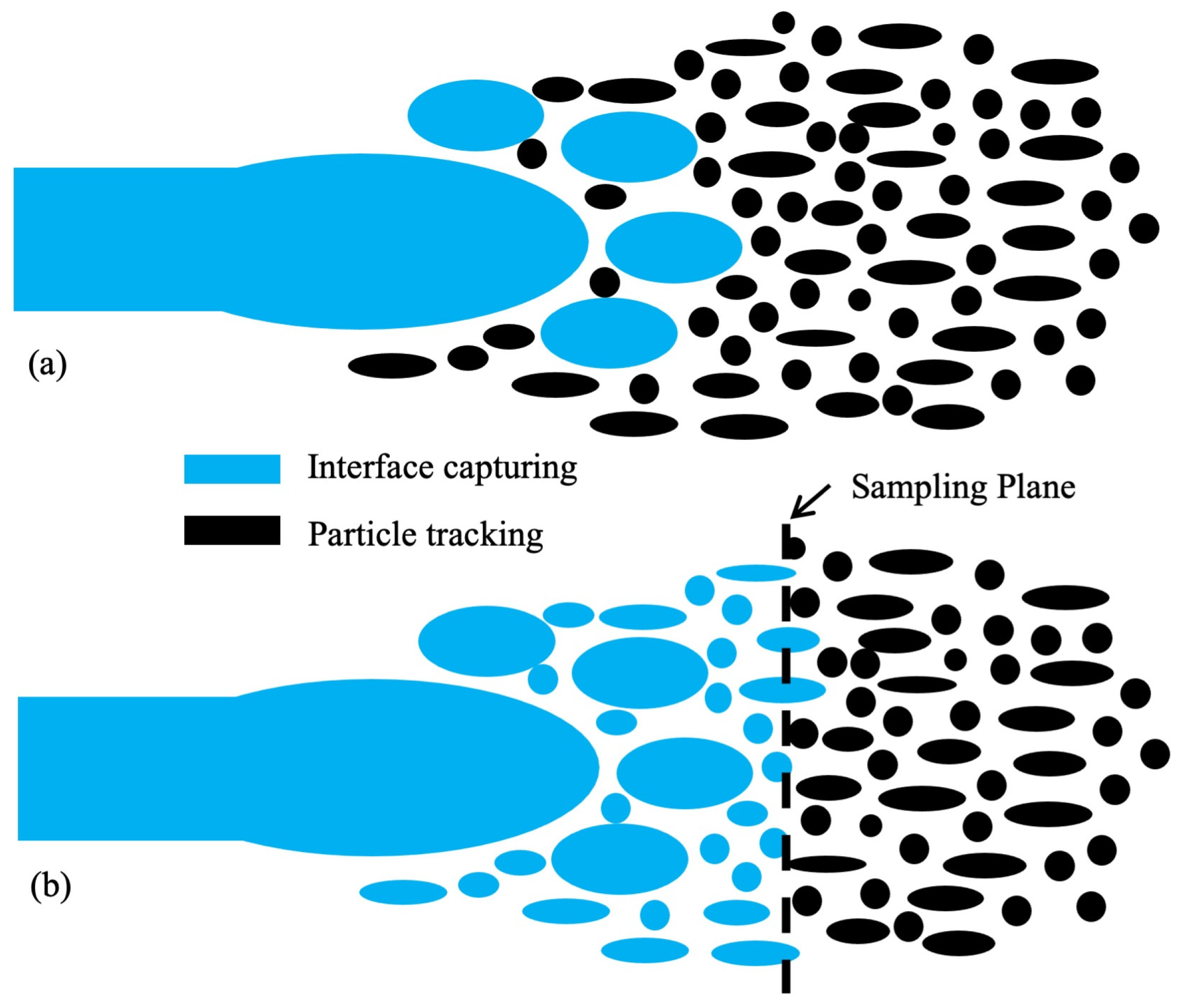
5. Hybrid of Interface Capturing and Particle Tracking

According to the analysis in Section 3 and Section 4, it can be seen that the interface capturing method is able to preserve most first principal theories relying on minor empirical relations while the particle tracking method must rely on various semi-empirical breakup models to guarantee the simulation accuracy. The advantage of the interface capturing method is its precise prediction on the local interface evolvement, which inherently includes the primary and secondary breakup. Its disadvantage lies in the great computer cost or very limited computation domain. In contrast, the particle tracking method is able to cover a much broader flow field while computationally inexpensive. As a result, there comes a simulation method of atomization that combines the merits of both above methods.

5.1. Basic Idea

The atmosphere is always in Eulerian manner while the liquid phase is conditionally treated as Eulerian phase or Lagrangian phase for interface capturing and particle tracking methods, respectively. In the hybrid method, the liquid in the primary atomization is mostly Eulerian phase, while the liquid in the secondary atomization is usually Lagrangian phase. This classification is not absolute since in practice there are two ways of mixing the interface capturing and particle tracking. The first way is to transform any liquid masses that have detached from the liquid core in Eulerian phase into Lagrangian phase as long as they meet the criteria such as size and sphericity. As shown in Figure 4a, the transformation to DPM (discrete particle method) particles is able to occur anywhere in the flow field. Several levels of grid refinement must be employed to sufficiently resolve the interfaces and after the removal of qualified liquid parcels from the Eulerian field, the grid would be reverted. Small time steps must be applied throughout the whole calculation domain to guarantee the small Courant number, thus wasting computer resources for the Lagrangian region. As a substitute shown in Figure 4b, the transformed DPM particle can be sampled on either a cut plane or the outlet boundary of the domain, and the information for every particle including location and speed be saved into a file, after which the injection file can be used for another particle tracking simulation. By doing so, a larger time step can be used on the Lagrangian phase, thus greatly saving computer cost.

5.2. Application Cases

Estivalèzes et al. [63] proposed a criterion to judge if a connect liquid domain or so-called liquid inclusion should be transferred into Lagrangian particles. Taking 3D simulation for example, Nl was noted as the number of cells in a liquid inclusion. If Nl is less than 8, the inclusion is automatically treated as a Lagrangian phase and if Nl is larger than 216, the inclusion is still treated by the Eulerian CLSVOF method until a possible stabilization or fragmentation stemming from Eulerian calculation occurs. For liquid inclusion 8 < Nl < 216, a sphericity criterion is used. rp is taken as the radius of the sphere of equivalent volume to the liquid inclusion, Vl is the inclusion volume, δl and δV are defined as the difference of characteristic length and volume, respectively, as shown below:
δ l = r p L   δ v = V c e l l χ i
where L is the smallest distance between the sphere center and inclusion interface, i is the cell index for each grid of the inclusion, Vcell is the volume of each grid, and χ is 1 if the cell is located outside the sphere and 0 if inside the sphere. Upon the above definition, one liquid inclusion can be judged as Lagrangian particle if:
δ l r p < C a δ V V l < C b
where Ca and Cb are coefficients being set as 0.5 and 1, respectively.
Duarte et al. [64] performed a comparison study between VOF and fine grid volume tracking (FGVT) methods with their in-house MFSim code. They focused on the primary atomization of liquid jet in crossflow. LES turbulence model was adopted in the Eulerian region and a simple transition criterion to Lagrangian region was based on two prerequisites show below:
V d r o p < V c r i t e r i o n   &   r m a x < 2 3 4 π V d r o p 3
The transition occurs if the continuous liquid ligament has a Vdrop smaller than Vcriterion, and its maximum radius rmax must be less than twice that of the sphere of equivalent volume.
Wei et al. [65] analyzed the atomizing powder preparation of 24CrNiMoY alloy steel for additive manufacturing. For the primary atomization very close to the nozzle exit, LES was cooperated into VOF to resolve the interface, and for the secondary atomization DPM was used together with SST k-ω model. The secondary breakup was also accounted for by the competition between breaking mechanisms of KH and TAB breakup models. Two grid systems with different grid refinement levels were employed for the VOF and DPM, respectively. The transition from Eulerian phase to Lagrangian was through sampling the particles near the end of primary atomization, saving to an extra file, and importing that particle information to another simulation.
The coupling between VOF and DPM was further improved to a twice incorporation manner by Luo et al. [66] in their powder preparation of AlSi10Mg. The VOF in the Fluent was used to take into account the liquid shear and primary atomization, after which the particles from three main injections were sampled and imported to a subsequent DPM simulation. In the DPM, the TAB model was used regarding the possible secondary breakup. After the breakup finishes, each droplet with the information from the DPM was once again imported into a VOF simulation, which only covers a smaller area with the same gas flow field extracted from the full-field simulation. The solidifying powders including hollow, satellite, and irregular powders, which are all unwished defects in the powder production, were analyzed, and some measures to avoid these defects were proposed.
A numerical study of atomization fully covering from inside the nozzle until far away was present in Yu et al. [67]. Inside the nozzle, a length of 24.2 mm of single-phase flow was solved by k-ε model. For the region of primary atomization corresponding to a length of 12 mm, VOF and LES were adopted. For the secondary atomization region with a length of 2988 mm, the DPM and k-ε model were adopted. Two artificial planes were used to divide the three regions with different grid densities created to improve simulation efficiency, and the data including the particles’ size and velocity were transferred across the plane by user-defined functions.
One of the complete simulations of primary and secondary atomization, evaporation, and combustion of acetone in air were performed by Wen et al. [68]. The Eulerian phase was assumed to transit into a Lagrangian phase in a predefined plane so as to form a hybrid interface capturing and particle tracking method. The combustion was accounted for through an LES-based flamelet progress variable model.
Despite advancements in multiscale modeling, critical gaps persist in current atomization simulations. First, phase transition criteria—such as sphericity thresholds [63] and volume-based rules [64]—rely heavily on empirical parameters rather than physics-driven metrics, causing significant errors in high-viscosity droplet predictions (27% for alloy steels [65]). Second, multiphysics couplings, particularly cavitation–turbulence interactions, remain underresolved, leading to 15% underestimation of primary breakup lengths in nozzle flows [67]. Third, validation frameworks lack cross-scale rigor, often focusing narrowly on particle size distributions while ignoring ligament dynamics [66]. These issues stem from fragmented modeling approaches that decouple interfacial, turbulent, and phase-change phenomena.
To address these limitations, three transformative directions are proposed. First, intelligent adaptive frameworks should integrate VOF, DPM, and SPH methods with reinforcement learning to dynamically allocate computational resources across scales—resolving primary breakup via CLSVOF-LES method, tracking secondary droplets with KH-RT-optimized DPM, and modeling microdroplets using ML-corrected SPH, achieving 5× faster simulations with <10% errors. Second, quantum annealing algorithms should optimize high-dimensional parameters (e.g., cavitation coefficients in ACT models), enabling 1000× faster calibration for aerospace injector designs. Third, industrial digital twins must unify embedded sensor networks, GPU-accelerated solvers, and PINN-based optimization to reduce defects in additive manufacturing. Supported by multimodal validation databases and initiatives, these strategies will bridge the gap between empirical models and predictive simulation.

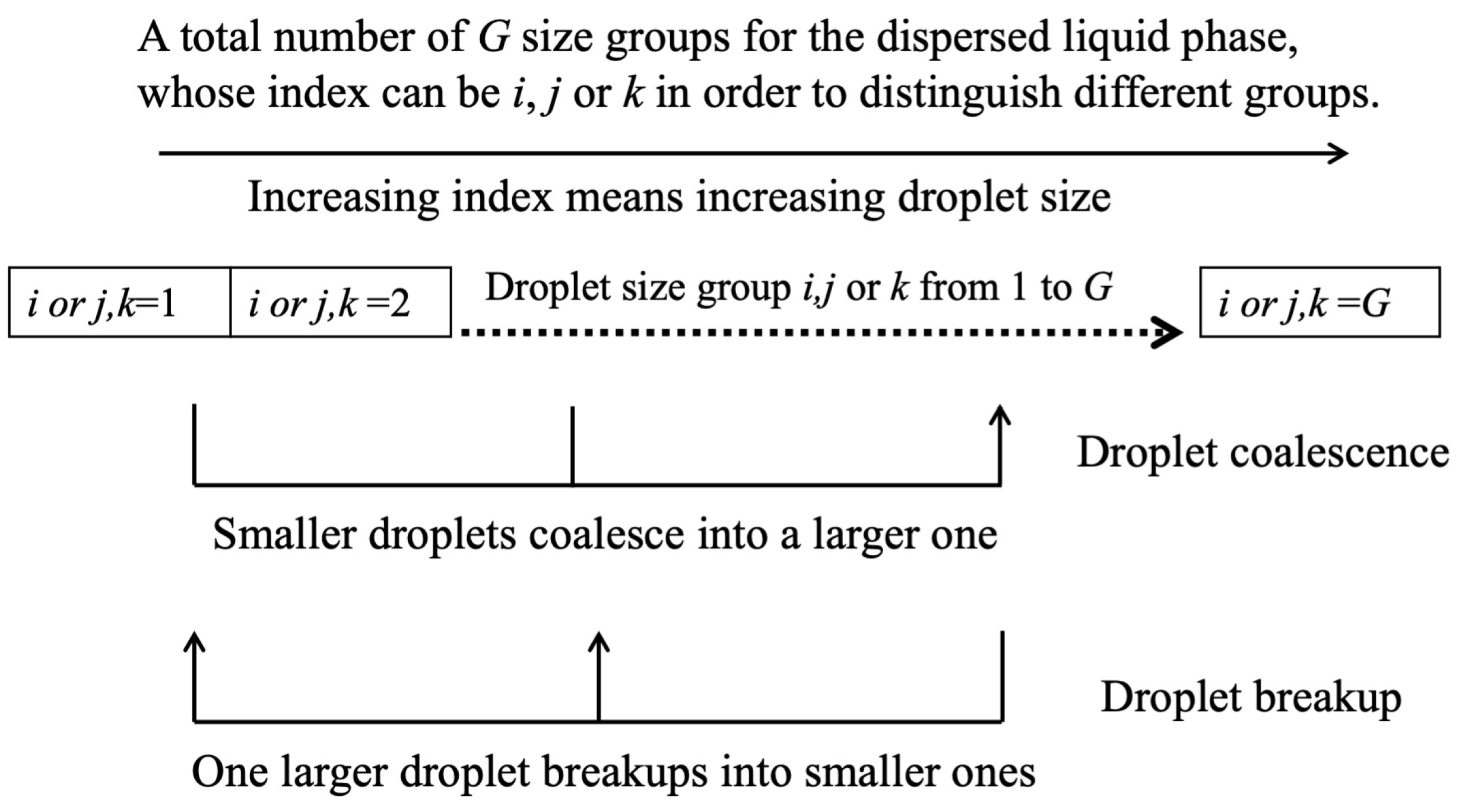
6. Multi-Fluid and Multi-Scale Eulerian Method

This method treats the atomization in Eulerian framework, but different from the LS or VOF method, it does not construct the interface during calculation. Instead, a few different Eulerian phases or so-called fluids, including continuous liquid, continuous gas, dispersed liquid, and dispersed gas, are assumed to be coexisting in the flow field. The dispersed liquid or gas are further treated as droplets or bubbles with a limited number of sizes but enough to cover all the possible scales of the dispersed phase. Based upon this, this method was named as multi-fluid and multi-scale (MFMS) method.

6.1. Theoretical Bases

The transitions from continuous fluids to dispersed fluids are bidirectional, and there can be momentum transfer between the couples of continuous liquid and continuous gas, continuous liquid and dispersed gas, and continuous gas and dispersed liquid. The control equations for the fluids, the mass and momentum transfer among fluids, as well as the breakup and coalescence of the different scales of dispersed phases are all in the Eulerian framework. It relies on various semi-empirical correlations to obtain the mass transitions and interface scale transformation. A high-resolution turbulence model was usually unnecessary, and thus this method is computationally inexpensive.
The momentum interactions exerted by the different interface topologies between continuous liquid and continuous gas can be dealt with by an algebraic interfacial area density (AIAD) model [69]. Regardless of the specific interface geometry, the volumetric drag force density in between is expressed as:
M c l = M c g = 0.5 C D A ρ U 2
where CD is the dimensionless drag coefficient, A is the interfacial area density, U is the relative velocity and ρ is the volume fraction-weight averaged density of the two phases. Mcl and Mcg are the interfacial forces exerted to each phase by another phase, of course through the interface.
The AIAD mixes the contributions of three interface topologies, namely dispersed droplets, dispersed bubbles, and continuous surface into interfacial area density A and drag coefficient CD by three blending functions [70], as shown below:
f D = [ 1 + e a D α c l α D , l i m i t ] 1 f B = [ 1 + e a B α c g α B , l i m i t ] 1 f F S = 1 f D f B  
where D, B, and FS represent droplet, bubble, and continuous free surface, respectively, and αcl and αcg are the volume fraction of continuous liquid and gas. Note that since there are more than two phases, the summation of αcl and αcg is less than unit. The other constants usually have the following value: aD = aB = 70 and αD,limit = αB,limit = 0.3.
By adopting proper models for the interfacial area densities and drag force coefficients for each of the three interface topologies, the CD and A in Equation (36) can be obtained by their summation weighted by the blending functions in Equation (37).
The momentum interactions between a continuous phase and a dispersed phase (continuous liquid with bubbles, continuous gas with droplets) can still be taken care of by the particle model. Comparing the relative magnitudes, drag force, lift force, and turbulent dispersion force are usually considered to be important, and their formulations are no difference from those in particle tracking method.
The disintegration of droplets from the continuous liquid or the primary breakup has to be accounted for by sub-grid models since the coarsen grid system is not precise enough to produce exact interface structure. According to the theory of Faeth et al. [71], a droplet with size of the eddy can be disintegrated out of continuous surface if the addition of turbulent energy of an eddy and the aerodynamic energy exerted by the flowing gas can overcome the surface tension energy, which can be written as
C R = ρ c l v f l 2 + C a ρ c g u g 2 λ 3 C s σ λ 2 > 0
where Ca and Cs are empirical constants. vfl is the velocity fluctuations vertical to the surface of the continuous liquid. The eddy size λ is modeled by turbulent kinetic energy k, viscosity ν and dissipation rate ε as follow [72]:
λ = 10 ν k ε
If the criteria in Equation (38) are satisfied, the disintegrating mass rate from the continuous liquid to dispersed liquid reads [73]:
S d l = S c l = ρ c l v f l π λ 6 x
where Sdl is the mass gain for the dispersed phase and Scl is the mass loss for the continuous phase.
The disintegrated liquid droplets or gas bubbles are referred to as the dispersed interface. The variation of the sizes is referred to as change of interface scales. In the multi-scale method, the change of the interface scales can be realized by discrete population balance model. Using the dispersed droplets as an example as shown in Figure 5, a discrete number of size groups G is set covering the possible minimum and maximum range of the droplet size. Increasing the number of size groups improves the accuracy but would require more computer resources, and normally 6–9 groups was considered enough. Also, if the many size groups in a dispersed phase show great discrepancy in flow features such as a too-large difference in velocities between different scales, the dispersed phase can be further divided into several velocity groups, each of which contains several size groups. As matter of course, several more groups of N-S equations would be required, thus increasing the computer burden.
Mathematically, the net birth rate of a particular size group can be expressed by:
S i = ( B B + B C D B D C ) i
where BB is the droplet birth rate due to breakup of droplets large than the i-th size group, BC is the droplet birth rate due to the coalescence of droplets smaller than the i-th size group, DB is the death rate due to breakup of the i-th size group into smaller droplets and DC is the death rate due to coalescence of i-th size group with other size group. Currently, the breakup rate and coalescence rate can be calculated from the Luo and Svendsen model [74] and Prince and Blanche model [75], respectively. Since these two models are derived from bubbles breakup or coalescence, future efforts need to be dedicated to building models regarding droplet breakup or coalescence.

6.2. Application Cases

A fully Eulerian-based MFMS method has been applied in the simulation of gas–liquid flow in a pipe [76], liquid column impinging into a free surface [77], a dam break [78], and boiling flow in a heated pipe [79]. The simulations were usually conducted on the commercial code CFX, utilizing the inhomogeneous MUlti-SIze Group (iMUSIG) model, which is a kind of discrete population balance model. Except the theories shown in Section 6.1, multiple sub-grid turbulence models and turbulence dumping need to be included since avoiding using LES or DNS is the aim of MFMS, intended for applications in practical and efficient engineering design.
Application of MFMS on jet flow is rare in the literature. The authors of the present paper have performed a simulation of an air jet injected into water [80], with air as the dispersed gas phase and water as the continuous liquid phase, both in a Eulerian framework. Since the bubble sizes were observed ranging from 1 to 10 mm, much velocity discrepancy was expected, and the dispersed phase was divided into two velocity groups and six size groups, thus forming a three-phase Eulerian simulation. The distribution of bubble size as well as the gas volume fraction were in better agreement with the electricity probe measurement than the mono-dispersed or homogeneous MUSIG methods.
For the simulation of jet atomization, we also developed a three-phase Eulerian method, which contains continuous gas, continuous liquid, and dispersed liquid [81]. Nine groups of droplet size from 10 um to 160 um were assumed for the dispersed liquid phase. An RMS turbulence model and the turbulence criteria shown in equations from (38) to (40) were adopted for obtaining the transition rates from continuous liquid to dispersed liquid. The computational domain with a length of 0.5 m was meshed by two million cells, which is more acceptable than the interface capturing method for practical engineering usage. The comparison with the experiment reveals reasonable agreement in aspects such as jet spreading, droplet coalescence, and distribution of droplet sizes. However, this study only serves as a primary exploration, and it is necessary to adjust the parameters of the droplet collision model or to develop a new model to take care of the secondary evolvement of the droplets and hence better predict the droplet size distribution downstream. To realize this, more experimental measures must be carried out for validation purposes.

7. Smoothed Particle Hydrodynamics

As a non-grid method, Smoothed Particle Hydrodynamics (SPH) has some advantages in tracking multiphase flow over grid-based method, mainly because the diffusive effects at the interface can be avoided.
The SPH method was originally developed in the context of astrophysics [82,83]. The numerical discretization elements are particles fulfilled into the whole domain and the motivation for using Lagrangian framework was to avoid the discretization of large, empty interstellar spaces. In many two-phase flows, the less important gas phase is allowed to be omitted without particles representing it, thus saving massive computational effort. This is not the case for the atomization process since the gas flow plays an essential role. Particles representing either liquid or gas phase are tracked with identical equations and are discriminated through properties such as density. Density ratios of liquid to gas less than 1000 can be handled without any stability issues. No explicit interface tracking or capturing is needed, and interface diffusion is inherently avoided, so SPH is suitable for simulating multiphase flow with severe interface deformations like liquid atomization.
The main idea behind the SPH is to evaluate the physical property of a particle or its derivative by interpolating over neighbor particles within a certain cut-off radius, and the basic interpolation formalism for a particle with index i is:
Φ i = j V j Φ j W ( x i x j , h )
where Φ is a physical quantity, Vj is the volume of a neighbor particle j, W is a weighting function, depending on the distance between particle i and j, and h is the smoothing length, which defines the cut-off radius. The density formulation is proposed by Hu and Adams [84] as:
ρ i = m i j W i j
The contributions by the pressure gradient [85] and viscous force [86] to the conservation of momentum can be described by the following Equations (44) and (45):
F i , p = j m j ( p i + p j ) ρ i ρ j W i j
F i , μ = j 2 m j ( d + 2 ) ( υ i + υ j ρ i + ρ j v i j r i j r i j 2 + η 2 ) W i j
where d denotes the dimensionality and η is a small constant to avoid divisions by zero.
The SPH method also has some disadvantages. For instance, neither the consistency of the method nor the convergence have been proven mathematically. The interpolation accuracy is strongly affected by the particle arrangement. This feature resembles the influence of grid quality in grid-based methods. The introduction of the background pressure described previously, in order to regularize the particle arrangement, can improve interpolation accuracy only to a certain extent. However, due to the extremely high numerical efficiency, it is often possible to carry out simulations with a much finer resolution than with conventional methods. This high spatial resolution is indispensable if primary atomization is to be simulated.
Igari et al. [87] used an incompressible SPH method in their simulation of the liquid flow scattering from a rotary atomizer. The influence of grooves at the edges of the atomizers on the formation of ligaments and droplets is investigated. It is found that small droplets are likely to be generated when the number of grooves is large and the depth of grooves is deep, and the grooves work more effectively in bell-cup atomizers than in disk-type atomizers.
Barun et al. [88] performed SPH simulation of an air-assisted pre-filming atomization in a dimension of 6 mm × 4 mm × 6 mm. The spatial resolution yields 1.2 billion particles, and a physical period of time of 14.6 ms cost their computer cluster 60 days of running time. Both thread-shaped liquid structures and bursts of liquid film bags have been successfully captured. The number of discretized elements was comparable to that of DNS simulation, but the authors claim SPH is superior in terms of efficiency and flexibility for the upcoming heterogeneous computer systems.

8. Summary and Outlook

Theoretically, the interface capturing method coupled with the DNS turbulence model is able to precisely replicate the observed atomization phenomena in any scale of all kinds of liquid and gas layout and shapes of nozzle. This is because it is based upon conservative fundamentals of mass, momentum, and energy, relying on no additional assumptions or empirical correlations. To acquire precise enough interface structures, the turbulence in the Kolmogorov scale has to be resolved, and the grid size must be in the same magnitude. The turbulence of both near and far away from the interface may produce a strong enough disturbance to transform interface topology and shape, so the method of adaptive mesh refinement based on the gradient of interface area density is sometimes not adequate. Moreover, the Kolmogorov scale decreases with increasing flow velocity, which further brings down the scale that has to be involved for liquid atomization as a well atomized flow intrinsically need high speed.
Limited by the current computer technology, the interface capturing method can only cover a small range that is a portion of the primary region near the nozzle exit. This method is now mainly for exploring atomization details, which are too fast and small scale to conduct experiment observation, and currently not suitable for engineering design purposes even with the supercomputer center. As a result, one research orientation of this method is attributed to developing high-performance computers, building clusters, and improving efficiency of parallel computing. Another research orientation is improving the computer iteration algorithms in order to save computational effort.
For the particle tracking method, the gas is treated in a Eulerian manner usually with a RANS-type turbulence model, requiring much coarser grids than the interface capturing method. The liquid, whether large liquid core or small liquid ligaments, is treated as blobs, parcels, or droplets tracked in the Lagrangian framework, which does not need grids. Therefore, it consumes realizable computational effort even with a personal computer and can predict full primary and secondary atomization in a broader range within a realizable amount of time. This method has been applied during the design of nozzles in the cooling tower, irrigation, and dust removal. However, since the instantaneous local interface is not constructed, the primary and secondary breakup of the liquid phase must be realized through constitutive models, which are actually semi-empirical formulations defining the transition rates between liquid core and droplets as well as among droplets of varying sizes.
It has been clarified that turbulence kinetic energy, surface tension, viscosity, and aerodynamic forces are the main factors determining the disintegrating rates, upon which various models were established. However, there remain two aspects opening for further research. Firstly, the accuracy of those constitutive models generating primary and secondary breakup rates needs to be improved to fit various layouts of atomization, speeds, and properties of liquid and gas and nozzle shapes because if those disintegrating and coalescences models need to be tuned for each kind of atomization, their level of confidence would be greatly compromised. This can be performed via thorough quantitative understanding of the controversial mechanisms that promote or suppress the breakup potential. Secondly, as the particle tracking method is able to cover a wider region of atomization, the collisions and coalescences of droplets far downstream probably occur and influence the distribution of droplet velocity and size severely. This phenomenon has not been fully considered and there are rarely models involved in the atomization process.
The hybrid method of interface capturing and particle tracking avoids a majority of the empirical models that particle tracking requires while making use of the initial droplets distribution from the interface capturing method. Except for struggling on the research subjects for both, the future research efforts should be made on the transition criteria from the Eulerian phase to Lagrangian phase. On the one hand, the shape and size upon which the liquid ligament reaches when the transition occurs should be quantitatively determined. On the other hand, when determining the transition criteria, the computational cost and accuracy should be balanced, since the interface capturing method and particle tracking method possesses the merits of simulation accuracy and efficiency, respectively.
Like the particle tracking method, the multi-fluid and multi-scale (MFMS) method also relies on various disintegration models accounting for the transitions among phases. The difference is that the former treats the liquid phase in a Lagrangian manner while the latter treats the liquid phase in a Eulerian manner. For the particle tracking method, the computational cost increases with the number of droplets since each of them needs a set of conservation equations. In contrast, the computational cost of the MFMS method is not sensitive to the complexity of the interface topology; instead, it mainly depends on the calculation domain and number of cells. As a result, the MFMS method embraces more flexibility when the number of droplets is enormous or when the simulation domain has a complex layout. However, the available transition models among phases for MFMS are rarer than the breakup models for particle tracking methods. Fortunately, the mechanisms for the transitions in the MFMS method also stem from the same influential factors such as turbulence kinetic energy, surface tension, viscosity, and aerodynamic forces. Therefore, after adequate validation against experiments, it is possible those breakup models shown in Section 4.2 can be reformulated into utilization in the full Eulerian framework.
The non-grid methods, such as the SPH method mentioned above and the lattice Boltzmann method (LBM), are new emerging methods intending to overcome the discontinuity and diffusive effects at the interface encountered by grid-based methods. The calculation domain is discretized by particles or lattices without discriminating between gas and liquid. The cost of computer resources is claimed to be less than the DNS method with the same accuracy. However, their studies are currently more behind than the grid-based methods for practical usage, mainly because the theoretical fundamentals of these methods are still developing, including the processing of initial and boundary conditions and inadequacy in proving consistency and convergence.

Author Contributions

Conceptualization, L.L. and X.Q.; formal analysis, G.W.; investigation, L.L.; resources, X.Q.; writing—original draft preparation, L.L.; writing—review and editing, G.W.; project administration, X.Q.; funding acquisition, X.Q. and G.W. All authors have read and agreed to the published version of the manuscript.

Funding

This research was sponsored by Natural Science Foundation of Chongqing, China (CSTB2022NSCQ-MSX1302), National Natural Science Foundation of China (52276157), Natural Science Fund for Outstanding Young Scholars of Shandong Province (ZR2023YQ048), and Fund for Taishan Youth scholars of Shandong Province (tsqn202408179).

Institutional Review Board Statement

Not applicable.

Informed Consent Statement

Not applicable.

Data Availability Statement

The data presented in this article are available upon request from the corresponding authors.

Acknowledgments

The authors are grateful to the anonymous reviewers for their careful review and constructive comments.

Conflicts of Interest

The authors declare no conflicts of interest.

Abbreviations

The following abbreviations are used in this manuscript:
ACTaerodynamic–cavitation–turbulence
AIADalgebraic interfacial area density
AMRadaptive mesh refinement
DNSdirect numerical simulation
DPMdiscrete particle method
FGVTfine grid volume tracking
GFMghost fluid method
HGHuh–Gosman
iMUSIGinhomogeneous MUlti-SIze Group
KHKelvin–Helmholtz
LBMlattice Boltzmann method
LESlarge eddy simulation
LSlevel set
MFMSmulti-fluid and multi-scale
RANSReynolds-averaged Navier-Stokes
RTRayleigh–Taylor
SGSstudied sub-grid scale
SPHsmoothed particle hydrodynamics
TABTaylor analogy breakup
VOFvolume of fluid
WFWu–Faeth

References

  1. Opfer, L.; Roisman, I.V.; Tropea, C. Primary Atomization in an Airblast Gas Turbine Atomizer; Springer: Dordrecht, The Netherlands, 2013. [Google Scholar]
  2. Salvador, F.; Romero, J.-V.; Roselló, M.-D.; Jaramillo, D. Numerical simulation of primary atomization in diesel spray at low injection pressure. J. Comput. Appl. Math. 2016, 291, 94–102. [Google Scholar] [CrossRef]
  3. Solomatin, Y.; Shlegel, N.E.; Strizhak, P.A. Atomization of promising multicomponent fuel droplets by their collisions. Fuel 2019, 255, 115751. [Google Scholar] [CrossRef]
  4. Zhang, S.; Alavi, S.; Kashani, A.; Ma, Y.; Zhan, Y.; Dai, W.; Li, W.; Mostaghimi, J. Simulation of Supersonic High-Pressure Gas Atomizer for Metal Powder Production. J. Therm. Spray Technol. 2021, 30, 1968–1994. [Google Scholar] [CrossRef]
  5. Mullis, A.M.; Kumar, A.P.A.; Borman, D.J. CFD Modelling of High Pressure Gas Atomization of Liquid Metals. In CFD Modeling and Simulation in Materials Processing 2018; Springer: Cham, Switzerland, 2018; pp. 77–84. [Google Scholar]
  6. Xu, Q.; Cheng, D.; Trapaga, G.; Yang, N.; Lavernia, E. Numerical analyses of fluid dynamics of an atomization configuration. J. Mater. Res. 2002, 17, 156–166. [Google Scholar] [CrossRef]
  7. Zhao, X.; Xu, J.; Zhu, X.; Zhang, S. Effect of atomization gas pressure variation on gas flow field in supersonic gas atomization. Sci. China Technol. Sci. 2009, 52, 3046–3053. [Google Scholar] [CrossRef]
  8. Mantripragada, V.T.; Kumar, K.; Kumar, P.; Sarkar, S. Modeling of Powder Production During Centrifugal Atomization. J. Sustain. Met. 2021, 7, 620–629. [Google Scholar] [CrossRef]
  9. Hernandez, F.; Riedemann, T.; Tiarks, J.; Kong, B.; Regele, J.D.; Ward, T.; Anderson, I.E. Numerical Simulation and Validation of Gas and Molten Metal Flows in Close-Coupled Gas Atomization. In TMS 2019 148th Annual Meeting & Exhibition Supplemental Proceedings; Springer: Cham, Switzerland, 2019; pp. 1507–1519. [Google Scholar]
  10. Wang, J.; Zhou, G.; Wei, X.; Wang, S. Experimental characterization of multi-nozzle atomization interference for dust reduction between hydraulic supports at a fully mechanized coal mining face. Environ. Sci. Pollut. Res. 2019, 26, 10023–10036. [Google Scholar] [CrossRef]
  11. Kou, B.-F.; Liu, Q.-Z.; Cao, S.-C.; Hu, X.-H.; Li, Y.-F.; Wang, Y.-R.; Zhao, B.-H. Experimental investigation on atomization and collecting efficiency of wind-spray dust controller and its parameters optimization. J. Central South Univ. 2015, 22, 4213–4218. [Google Scholar] [CrossRef]
  12. Yin, W.; Zhou, G.; Gao, D. Simulation analysis and engineering application of distribution characteristics about multi-stage atomization field for cutting dust in fully mechanized mining face. Adv. Powder Technol. 2019, 30, 2600–2615. [Google Scholar] [CrossRef]
  13. Musiu, E.M.; Qi, L.; Wu, Y. Evaluation of droplets size distribution and velocity pattern using Computational Fluid Dynamics modelling. Comput. Electron. Agric. 2019, 164, 104886. [Google Scholar] [CrossRef]
  14. Ishii, M.; Hibiki, T. Thermo-Fluid Dynamics of Two-Phase Flow; Springer: New York, NY, USA, 2010. [Google Scholar]
  15. Liu, J.; Li, Q.; Zhen, Z.; Wu, H. Numerical simulation of flow field in pressure-swirl injector based on VOF interface tracking method. J. Aerosp. Power 2011, 26, 1986–1994. [Google Scholar]
  16. Wang, D.; Liu, J.; Li, Q.; Ni, G.; Wang, S. Investigation on the Influence of Pressure on Enhancing Atomization Effect of Molten Metal Stream. Trans. Indian Inst. Met. 2024, 77, 2787–2795. [Google Scholar] [CrossRef]
  17. Chen, R.; Li, H.; Wang, J.; Guo, X. Effects of Pressure and Nozzle Size on the Spray Characteristics of Low-Pressure Rotating Sprinklers. Water 2020, 12, 2904. [Google Scholar] [CrossRef]
  18. Cui, L.; Sun, Y.; Zhou, Z.; Sun, Z.; Xi, G. Numerical Study of Double Jet Impact Atomization Using Meshless MPS Method. J. Eng. Thermophys. 2024, 45, 1385–1394. [Google Scholar]
  19. Grosshans, H.; Szász, R.-Z.; Fuchs, L. Enhanced liquid–gas mixing due to pulsating injection. Comput. Fluids 2015, 107, 196–204. [Google Scholar] [CrossRef]
  20. Nygård, A.; Altimira, M.; Semlitsch, B.; Wittberg, L.P.; Fuchs, L. Analysis of vortical structures in intermittent jets. In Proceedings of the 5th International Conference on Jets, Wakes and Separated Flows (ICJWSF2015), Stockholm, Sweden, 15–18 June 2015; Springer Proceedings in Physics. Springer: Cham, Switzerland, 2016; Volume 185, pp. 3–10. [Google Scholar]
  21. Lehmkuhl, O.; Mira, D.; Gasparino, L.; Owen, H.; Houzeaux, G. Large-Eddy Simulation of Primary Atomization Using an Entropy Stable Conservative Level Set. In Direct and Large Eddy Simulation XII; Springer: Cham, Switzerland, 2020; pp. 207–213. [Google Scholar]
  22. Shao, C.; Luo, K.; Yang, Y.; Fan, J. Detailed numerical simulation of swirling primary atomization using a mass conservative level set method. Int. J. Multiph. Flow 2017, 89, 57–68. [Google Scholar] [CrossRef]
  23. Pizziol, B.; Costa, M.; Panão, M.O.; Silva, A. Multiple impinging jet air-assisted atomization. Exp. Therm. Fluid Sci. 2018, 96, 303–310. [Google Scholar] [CrossRef]
  24. Braun, S.; Wieth, L.; Holz, S.; Dauch, T.F.; Keller, M.C.; Chaussonnet, G.; Gepperth, S.; Koch, R.; Bauer, H. Numerical prediction of air-assisted primary atomization using Smoothed Particle Hydrodynamics. Int. J. Multiph. Flow 2019, 114, 303–315. [Google Scholar] [CrossRef]
  25. Nambu, T.; Mizobuchi, Y. Detailed numerical simulation of primary atomization by crossflow under gas turbine engine combustor conditions. Proc. Combust. Inst. 2021, 38, 3213–3221. [Google Scholar] [CrossRef]
  26. Liu, R.; Zhong, L.; Li, S.; Li, J.; Ji, H. Numerical investigation on the spray characteristics of biodiesel with gas-assisted atomization injection. Fuel 2023, 358, 130178. [Google Scholar] [CrossRef]
  27. Xu, T.; Yang, F.; Zhu, M.; Ye, T.; Zhou, J.; Song, Y. Numerical simulation of spray atomization in crossflow using an empirical primary atomization model. Int. J. Multiph. Flow 2024, 174, 104768. [Google Scholar] [CrossRef]
  28. Zhang, T.; Mu, X.; Ge, S.; Li, S.; Ren, S.; Zhao, S.; Tao, S. Supersonic coaxial aerodynamic atomization dust removal technolo. Powder Technol. 2024, 444, 120076. [Google Scholar]
  29. Wang, Y.; Zhang, P.; Li, W.; Liu, Y.; Yan, Y. Experimental investigation of the atomization characteristics of pre-filming atomizer with low-temperature fuel. Phys. Fluids 2024, 36, 125159. [Google Scholar] [CrossRef]
  30. Dumouchel, C. On the experimental investigation on primary atomization of liquid streams. Exp. Fluids 2008, 45, 371–422. [Google Scholar] [CrossRef]
  31. Olyaei, G.; Kebriaee, A. Experimental study of liquid jets injected in crossflow. Exp. Therm. Fluid Sci. 2020, 115, 110049. [Google Scholar] [CrossRef]
  32. Wu, P.-K.; Tseng, L.-K.; Faeth, G.M. Primary breakup in gas/liquid mixing layers for turbulent liquids. At. Sprays 1992, 2, 295–317. [Google Scholar] [CrossRef]
  33. Mashayek, A.; Ashgriz, N. Atomization of a Liquid Jet in a Crossflow. In Handbook of Atomization and Sprays; Springer: Boston, MA, USA, 2011; pp. 657–683. [Google Scholar] [CrossRef]
  34. Guildenbecher, D.R.; López-Rivera, C.; Sojka, P.E. Secondary atomization. Exp. Fluids 2009, 46, 371–402. [Google Scholar] [CrossRef]
  35. Luo, K.; Shao, C.; Chai, M.; Fan, J. Level set method for atomization and evaporation simulations. Prog. Energy Combust. Sci. 2019, 73, 65–94. [Google Scholar] [CrossRef]
  36. Brackbill, J.; Kothe, D.; Zemach, C. A continuum method for modeling surface tension. J. Comput. Phys. 1992, 100, 335–354. [Google Scholar] [CrossRef]
  37. Osher, S.; Sethian, J.A. Fronts propagating with curvature-dependent speed: Algorithms based on Hamilton-Jacobi formulations. J. Comput. Phys. 1988, 79, 12–49. [Google Scholar] [CrossRef]
  38. Warncke, K.; Gepperth, S.; Sauer, B.; Sadiki, A.; Janicka, J.; Koch, R.; Bauer, H.-J. Experimental and numerical investigation of the primary breakup of an airblasted liquid sheet. Int. J. Multiph. Flow 2017, 91, 208–224. [Google Scholar] [CrossRef]
  39. Huang, J.; Zhao, X. Numerical simulations of atomization and evaporation in liquid jet flows. Int. J. Multiph. Flow 2019, 119, 180–193. [Google Scholar] [CrossRef]
  40. Arachchilage, K.H.; Haghshenas, M.; Park, S.; Zhou, L.; Sohn, Y.; McWilliams, B.; Cho, K.; Kumar, R. Numerical simulation of high-pressure gas atomization of two-phase flow: Effect of gas pressure on droplet size distribution. Adv. Powder Technol. 2019, 30, 2726–2732. [Google Scholar] [CrossRef]
  41. Ketterl, S.; Reißmann, M.; Klein, M. Large eddy simulation of multiphase flows using the volume of fluid method: Part 2—A-posteriori analysis of liquid jet atomization. Exp. Comput. Multiph. Flow 2019, 1, 201–211. [Google Scholar] [CrossRef]
  42. Mingalev, S.; Inozemtsev, A.; Gomzikov, L.; Sipatov, A.; Abramchuk, T. Simulation of Primary Film Atomization in Prefilming Air-assisted Atomizer Using Volume-of-Fluid Method. Microgravity Sci. Technol. 2020, 32, 465–476. [Google Scholar] [CrossRef]
  43. Hua, D.; Zongfang, D.; Yanwei, L. Simulation and experimental research on the injection characteristics of the laser processing injection hole. J. Braz. Soc. Mech. Sci. Eng. 2021, 43, 202. [Google Scholar] [CrossRef]
  44. Pairetti, C.; Villiers, R.; Zaleski, S. On shear layer atomization within closed channels: Numerical simulations of a cough-replicating experiment. Comput. Fluids 2021, 231, 105125. [Google Scholar] [CrossRef]
  45. Mukundan, A.A.; Ménard, T.; de Motta, J.C.B.; Berlemont, A. Detailed numerical simulations of primary atomization of airblasted liquid sheet. Int. J. Multiph. Flow 2022, 147, 103848. [Google Scholar] [CrossRef]
  46. Gepperth, S.; Muller, A.; Koch, R.; Bauer, H.-J. Ligament and droplet characteristics in prefilming airblast atomization. In Proceedings of the 12th Triennial International Conference on Liquid Atomization and Spray Systems, Heidelberg, Germany, 2–6 September 2012. [Google Scholar]
  47. Chang, J.; Chen, L.; He, L.; Zhou, Y. Numerical simulation of primary atomization process of liquid jet in subsonic crossflow. Energy Rep. 2022, 8, 1–15. [Google Scholar] [CrossRef]
  48. Chryssakis, C.A.; Assanis, D.N.; Tanner, F.X. Atomization Models. In Handbook of Atomization and Sprays; Springer: Boston, MA, USA, 2011; pp. 215–231. [Google Scholar] [CrossRef]
  49. Huh, K.Y.; Gosman, A.D. A phenomenological model of diesel spray atomization. Int. Conf. Multiph. Flow 1991, 2, 515–518. [Google Scholar]
  50. Wu, P.-K.; Faeth, G.M. Aerodynamic effects on primary breakup of turbulent liquids. At. Sprays 1993, 3, 265–289. [Google Scholar] [CrossRef]
  51. Taylor, G.I. The Shape and Acceleration of a Drop in a High Speed Air Stream. In Scientific Papers of G. I. Taylor; Batchelor, G.K., Ed.; Technical Report; Cambridge University Press: Cambridge, UK, 1963. [Google Scholar]
  52. O’Rourke, P.J.; Amsden, A.A. The TAB Method for Numerical Calculation of Spray Droplet Breakup; SAE Technical Paper; SAE International: Warrendale, PA, USA, 1987; p. 872089. [Google Scholar] [CrossRef]
  53. Reitz, R.D. Mechanisms of Atomization Processes in High-Pressure Vaporizing Sprays. At. Spray Technol. 1987, 3, 309–337. [Google Scholar]
  54. Levich, V.G. Physicochemical Hydrodynamics; Prentice Hall: Hoboken, NJ, USA, 1962. [Google Scholar]
  55. Xin, J.; Ricart, L.; Reitz, R. Computer Modeling of Diesel Spray Atomization and Combustion. Combust. Sci. Technol. 1998, 137, 171–194. [Google Scholar] [CrossRef]
  56. Ye, X.; An, X.; Zhang, H.; Wang, S.; Guo, B.; Yu, A. Process simulation on atomization and evaporation of desulfurization wastewater and its application. Powder Technol. 2021, 389, 178–188. [Google Scholar] [CrossRef]
  57. Zhang, G.; Zhou, G.; Zhang, L.; Sun, B.; Wang, N.; Yang, H.; Liu, W. Numerical simulation and engineering application of multistage atomization dustfall at a fully mechanized excavation face. Tunn. Undergr. Space Technol. 2020, 104, 103540. [Google Scholar] [CrossRef]
  58. Shi, Y.; Lu, W.; Sun, W.; Zhang, S.; Yang, B.; Wang, J. Impact of gas pressure on particle feature in Fe-based amorphous alloy powders via gas atomization: Simulation and experiment. J. Mater. Sci. Technol. 2022, 105, 203–213. [Google Scholar] [CrossRef]
  59. Li, Z.-H.; He, B.-Q.; Zhao, H. Application of a hybrid breakup model for the spray simulation of a multi-hole injector used for a DISI gasoline engine. Appl. Therm. Eng. 2014, 65, 282–292. [Google Scholar] [CrossRef]
  60. Magnotti, G.M.; Genzale, C.L. Exploration of Turbulent Atomization Mechanisms for Diesel Spray Simulations; Georgia Institute of Technology: Atlanta, Georgia, 2017. [Google Scholar]
  61. Magnotti, G.M.; Genzale, C.L. Recent Progress in Primary Atomization Model Development for Diesel Engine Simulations. In Two-Phase Flow for Automotive and Power Generation Sectors; Springer: Singapore, 2019; pp. 63–107. [Google Scholar]
  62. Li, Y.; Huang, Y.; Luo, K.; Liang, M.; Lei, B. Development and validation of an improved atomization model for GDI spray simulations: Coupling effects of nozzle-generated turbulence and aerodynamic force. Fuel 2021, 299, 120871. [Google Scholar] [CrossRef]
  63. Estivalèzes, J.L.; Zuzio, D.; DiPierro, B. An Improved Multiscale Eulerian-Lagrangian Method for Simulation of Atomization Process. In Turbulence and Interactions; Springer: Cham, Switzerland, 2018; pp. 65–77. [Google Scholar]
  64. Duarte, B.A.d.F.; Barbi, F.; Villar, M.M.; Serfaty, R.; da Silveira Neto, A. Primary atomization of a turbulent liquid jet in crossflow: A comparison between VOF and FGVT methods. J. Braz. Soc. Mech. Sci. Eng. 2020, 42, 277. [Google Scholar] [CrossRef]
  65. Wei, M.; Chen, S.; Sun, M.; Liang, J.; Liu, C.; Wang, M. Atomization simulation and preparation of 24CrNiMoY alloy steel powder using VIGA technology at high gas pressure. Powder Technol. 2020, 367, 724–739. [Google Scholar] [CrossRef]
  66. Luo, S.; Wang, H.; Gao, Z.; Wu, Y.; Wang, H. Interaction between high-velocity gas and liquid in gas atomization revealed by a new coupled simulation model. Mater. Des. 2021, 212, 110264. [Google Scholar] [CrossRef]
  67. Yu, H.; Jin, Y.-C.; Cheng, W.; Yang, X.; Peng, X.; Xie, Y. Multiscale simulation of atomization process and droplet particles diffusion of pressure-swirl nozzle. Powder Technol. 2021, 379, 127–143. [Google Scholar] [CrossRef]
  68. Wen, J.; Hu, Y.; Nishiie, T.; Iino, J.; Masri, A.; Kurose, R. A flamelet LES of turbulent dense spray flame using a detailed high-resolution VOF simulation of liquid fuel atomization. Combust. Flame 2022, 237, 111742. [Google Scholar] [CrossRef]
  69. Ayad, F.; Baghdada, M.; Bouaichaoui, Y.; Höhne, T. Verification & validation of CFD predictions regarding pressurized thermal shock (PTS) situations in ROCOM installation: Comparison with IAEA benchmark. Nucl. Eng. Des. 2023, 413, 112498. [Google Scholar] [CrossRef]
  70. Höhne, T.; Vallée, C. Experiments and Numerical Simulations of Horizontal Two-Phase Flow Regimes Using an Interfacial Area Density Model. J. Comput. Multiph. Flows 2010, 2, 131–143. [Google Scholar] [CrossRef]
  71. Faeth, G.; Hsiang, L.-P.; Wu, P.-K. Structure and breakup properties of sprays. Int. J. Multiph. Flow 1995, 21, 99–127. [Google Scholar] [CrossRef]
  72. Pope, S. Turbulent Flows; Cambridge University Press: Cambridge, UK, 2000. [Google Scholar]
  73. Saeedipour, M.; Pirker, S.; Bozorgi, S.; Schneiderbauer, S. An Eulerian–Lagrangian hybrid model for the coarse-grid simulation of turbulent liquid jet breakup. Int. J. Multiph. Flow 2016, 82, 17–26. [Google Scholar] [CrossRef]
  74. Luo, H.; Svendsen, H.F. Theoretical Model for Drop and Bubble Breakup in Turbulent Dispersions. AIChE J. 1996, 42, 1225–1233. [Google Scholar] [CrossRef]
  75. Prince, M.J.; Blanch, H.W. Bubble Coalescence and Break-Up in Air-Sparged Bubble Columns. AIChE J. 1990, 36, 1485–1499. [Google Scholar] [CrossRef]
  76. Höhne, T.; Deendarlianto; Lucas, D. Numerical simulations of counter-current two-phase flow experiments in a PWR hot leg model using an interfacial area density model. Int. J. Heat Fluid Flow 2011, 32, 1047–1056. [Google Scholar] [CrossRef]
  77. Hänsch, S.; Lucas, D.; Krepper, E.; Höhne, T. A multi-field two-fluid concept for transitions between different scales of interfacial structures. Int. J. Multiph. Flow 2012, 47, 171–182. [Google Scholar] [CrossRef]
  78. Höhne, T.; Mehlhoop, J.-P. Validation of closure models for interfacial drag and turbulence in numerical simulations of horizontal stratified gas–liquid flows. Int. J. Multiph. Flow 2014, 62, 1–16. [Google Scholar] [CrossRef]
  79. Höhne, T.; Krepper, E.; Montoya, G.; Lucas, D. CFD-simulation of boiling in a heated pipe including flow pattern transitions using the GENTOP concept. Nucl. Eng. Des. 2017, 322, 165–176. [Google Scholar] [CrossRef]
  80. Qu, X.; Zhang, Y.; Qi, X.; Guo, Q. Modeling of gas jet flow into a liquid bath using the inhomogeneous poly-dispersed method. Prog. Nucl. Energy 2021, 137, 103773. [Google Scholar] [CrossRef]
  81. Qu, X.; Revankar, S.; Qi, X.; Guo, Q. Exploring on a three-fluid Eulerian-Eulerian-Eulerian approach for the prediction of liquid jet atomization. Appl. Therm. Eng. 2021, 195, 117160. [Google Scholar] [CrossRef]
  82. Gingold, R.A.; Monaghan, J.J. Smoothed particle hydrodynamics: Theory and application to non-spherical stars. Mon. Not. R. Astron. Soc. 1977, 181, 375–389. [Google Scholar] [CrossRef]
  83. Lucy, L.B. A numerical approach to the testing of the fission hypothesis. Astron. J. 1977, 82, 1013. [Google Scholar] [CrossRef]
  84. Hu, X.; Adams, N. A multi-phase SPH method for macroscopic and mesoscopic flows. J. Comput. Phys. 2006, 213, 844–861. [Google Scholar] [CrossRef]
  85. Colagrossi, A.; Landrini, M. Numerical simulation of interfacial flows by smoothed particle hydrodynamics. J. Comput. Phys. 2003, 191, 448–475. [Google Scholar] [CrossRef]
  86. Szewc, K.; Pozorski, J.; Minier, J. Analysis of the incompressibility constraint in the smoothed particle hydrodynamics method. Int. J. Numer. Methods Eng. 2012, 92, 343–369. [Google Scholar] [CrossRef]
  87. Igari, N.; Iso, T.; Nishio, Y.; Izawa, S.; Fukunishi, Y. Numerical simulation of droplet-formation in rotary atomizer. Theor. Appl. Mech. Lett. 2019, 9, 202–205. [Google Scholar] [CrossRef]
  88. Braun, S.; Koch, R.; Bauer, H.-J. Smoothed Particle Hydrodynamics for Numerical Predictions of Primary Atomization. In High Performance Computing in Science and Engineering ’16; Springer: Cham, Switzerland, 2016; pp. 321–336. [Google Scholar]
Figure 1. Atomization types (a) without and (b) with air-assisted [4,21,22,23,24,25].
Applsci 15 04928 g001
Figure 2. Primary breakup regimes for round jet (a) and crossflow (b). (a) Reprinted from Dumouchel [30]. (b) Reprinted from Olyaei and Kebriaee [31].
Applsci 15 04928 g002
Figure 3. Different secondary breakup regimes. Reprinted from Guildenbecher et al. [34].
Applsci 15 04928 g003
Figure 4. Two different ways of transiting the liquid Eulerian phase to Lagrangian phase. (a) transiting in the whole region. (b) transiting after a distance.
Applsci 15 04928 g004
Figure 5. Illustration of the discrete population balance model.
Applsci 15 04928 g005
Table 1. Dimensionless groups in liquid atomization.
NameAbbreviationExpression
Weber numberWe ρ U 2 d σ
Ohnesorge numberOh μ l ρ l d σ
Density Ratioε ρ l ρ g
Viscosity RatioN μ l μ g
Reynolds numberRe ρ U d μ
Momentum Ratioq ρ l U l 2 ρ g U g 2
Table 2. Comparison of commonly used mathematical modeling methods.
ReferenceMathematical ModelKey ParametersGrid SizeApplication Scenario
[28]VOF, LESGas–liquid velocity ratio, turbulence intensity~10 million cellsPrimary breakup of airblasted liquid sheets in combustion systems
[29]VOF, Level Set, Ghost Fluid MethodWeber number, Reynolds number, evaporation rate4.23 billion cellsAtomization and evaporation in turbulent liquid jet flows
[30]Two-phase CFD with Eulerian–Lagrangian couplingGas pressure (1–10 MPa), droplet Sauter mean diameter~1 million cellsHigh-pressure gas atomization for metal powder production
[31]LES with VOFTurbulence models, interfacial tension~5 million cellsLiquid jet atomization in multiphase flows
[32]Entropy-stable conservative Level SetSurface tension, viscosity, density ratioNot reportedPrimary atomization in fuel injectors
[33]VOF with adaptive mesh refinementAir–liquid momentum flux ratio, film thickness~3 million cellsPrefilming air-assisted atomizers in aerospace engines
[34]Experimental and CFD (ANSYS Fluent)Injection pressure, nozzle geometry~500,000 cellsLaser-processed fuel injection holes in automotive systems
[35]VOF with shear-stress transport (SST) modelsCough-induced shear flow, droplet size distribution~2 million cellsBiofluid atomization in respiratory systems
[36]High-resolution VOF and DNSTurbulent kinetic energy, breakup length scales6 billion cellsPrimary atomization of airblasted liquid sheets in industrial burners
[37]Experimental/PIV and LESLigament formation time, droplet velocityNot reportedPrefilming airblast atomization in gas turbines
[38]CLSVOF (Coupled Level Set/VOF)Crossflow velocity, jet-to-crossflow momentum ratio~100 million cellsLiquid jet atomization in subsonic crossflow (e.g., scramjet combustors)
Table 3. Comparison table of breakup models.
Model NameApplication ScenarioCore MechanismAdvantagesDisadvantages
Huh–Gosman (HG)Primary breakup in high-pressure nozzlesTurbulent eddy-driven interface instability1. Directly links nozzle turbulence parameters
2. High engineering usability
1. Relies on empirical constants (C1–C4)
2. Fails to capture secondary breakup
Wu–Faeth (WF)Primary breakup in transverse jetsTurbulence-surface wave coupling1. Incorporates radial turbulent integral scales
2. Suitable for non-axisymmetric flows
1. Requires precise nozzle exit measurements
2. Fails at high Weber numbers (We > 500)
TABLow-speed, low-We droplets (We < 100)Spring-mass-damper system analogy1. Physically intuitive
2. Low computational cost
1. Neglects shear-dominated breakup
2. Inapplicable to high-viscosity fluids (Oh > 0.1)
KHHigh Weber numbers (We > 100)Shear-induced surface wave instability1. Resolves rapid surface wave growth
2. Suitable for fuel injection
1. Neglects acceleration effects
2. Overpredicts small droplets (error ~20%)
KH-RTHigh-speed, high-pressure multiphase flows (e.g., IC engines)Shear (KH) + acceleration (RT) instability1. Dual-mechanism coupling improves accuracy
2. Industrially validated
1. High computational complexity
2. Requires manual liquid core region (L) definition
Disclaimer/Publisher’s Note: The statements, opinions and data contained in all publications are solely those of the individual author(s) and contributor(s) and not of MDPI and/or the editor(s). MDPI and/or the editor(s) disclaim responsibility for any injury to people or property resulting from any ideas, methods, instructions or products referred to in the content.

