
Super Twisted Sliding Mode Observer for Enhancing Ventilation Drive Performance


Abstract
1. Introduction
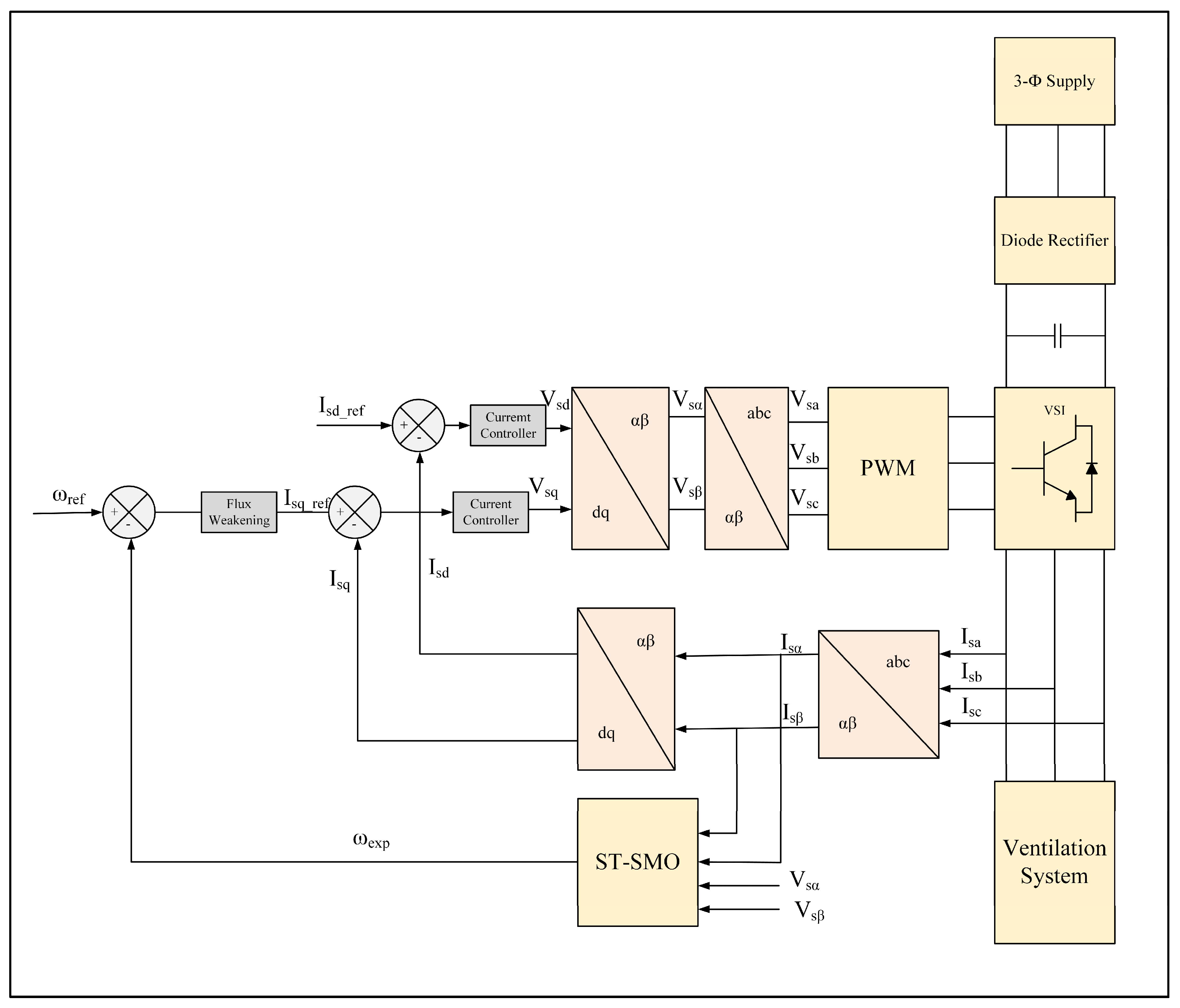
2. System Modelling
2.1. IM Modeling
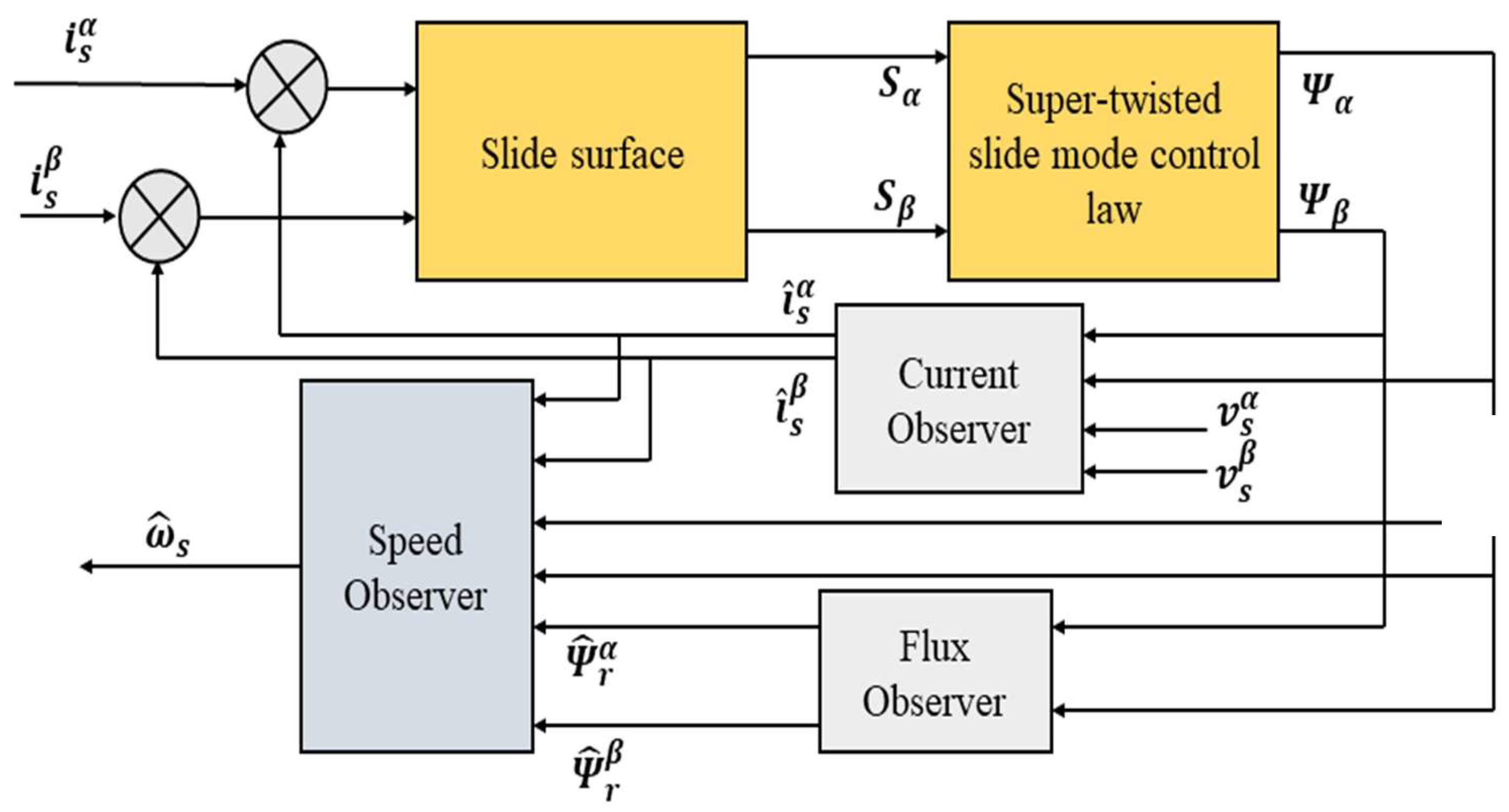
2.2. Super-Twisted Slide Mode Observer (ST-SMO) Speed Estimator
2.2.1. Super Twisting Algorithm (STA)
2.2.2. Current Observer
2.2.3. Stability Analysis
2.2.4. Flux and Rotor Speed Observers
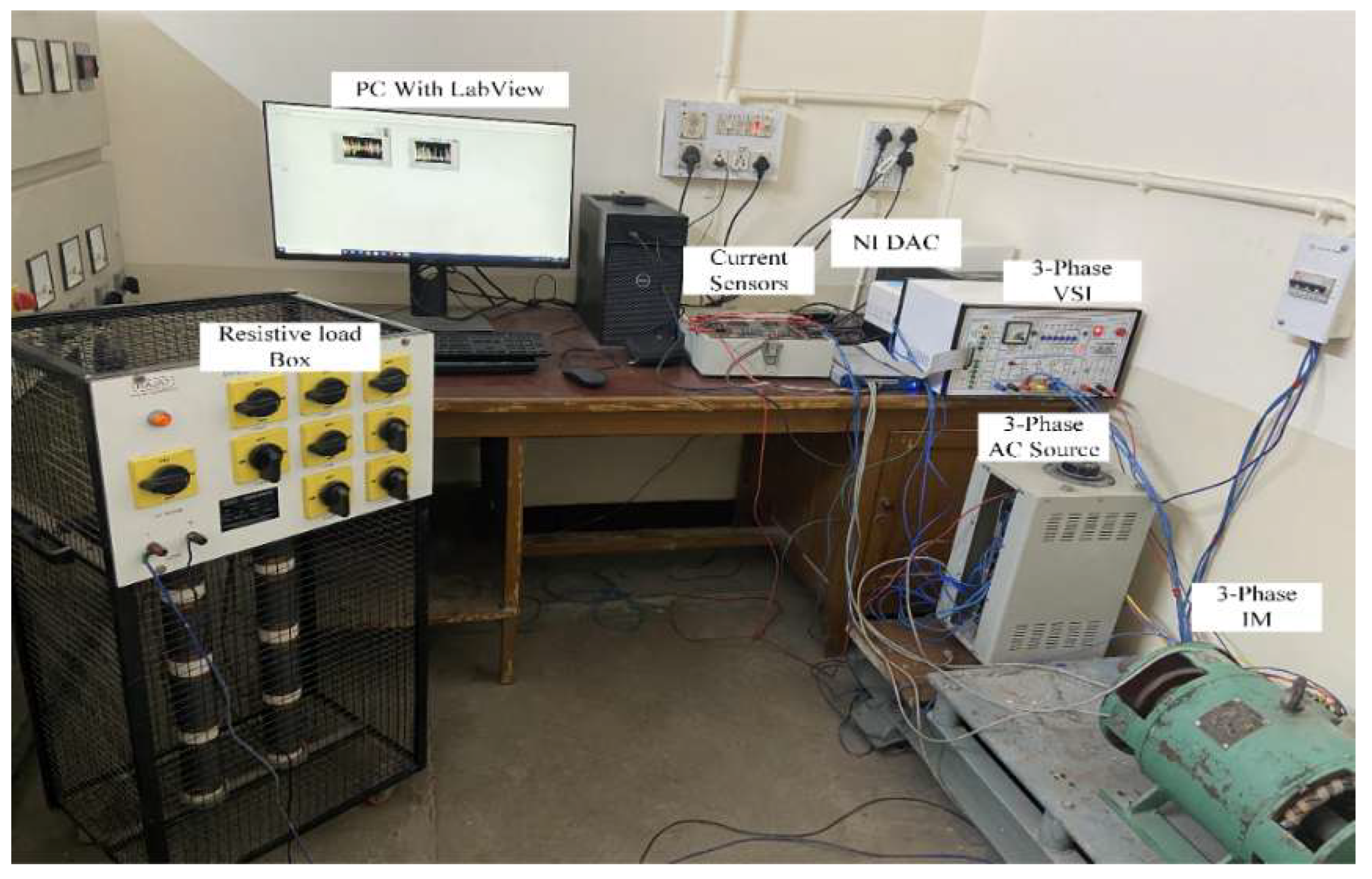
3. Experimental Setup and Results
3.1. Experimental Setup
3.2. Results and Discussion
- Case 1: Sensorless vector control encounters challenges at near-zero speed during no-load operation. Figure 4a compares the performance of the traditional MRAS with the STSMO-based MRAS. Notably, the STSMO-based MRAS demonstrates stable steady-state performance under the given conditions.
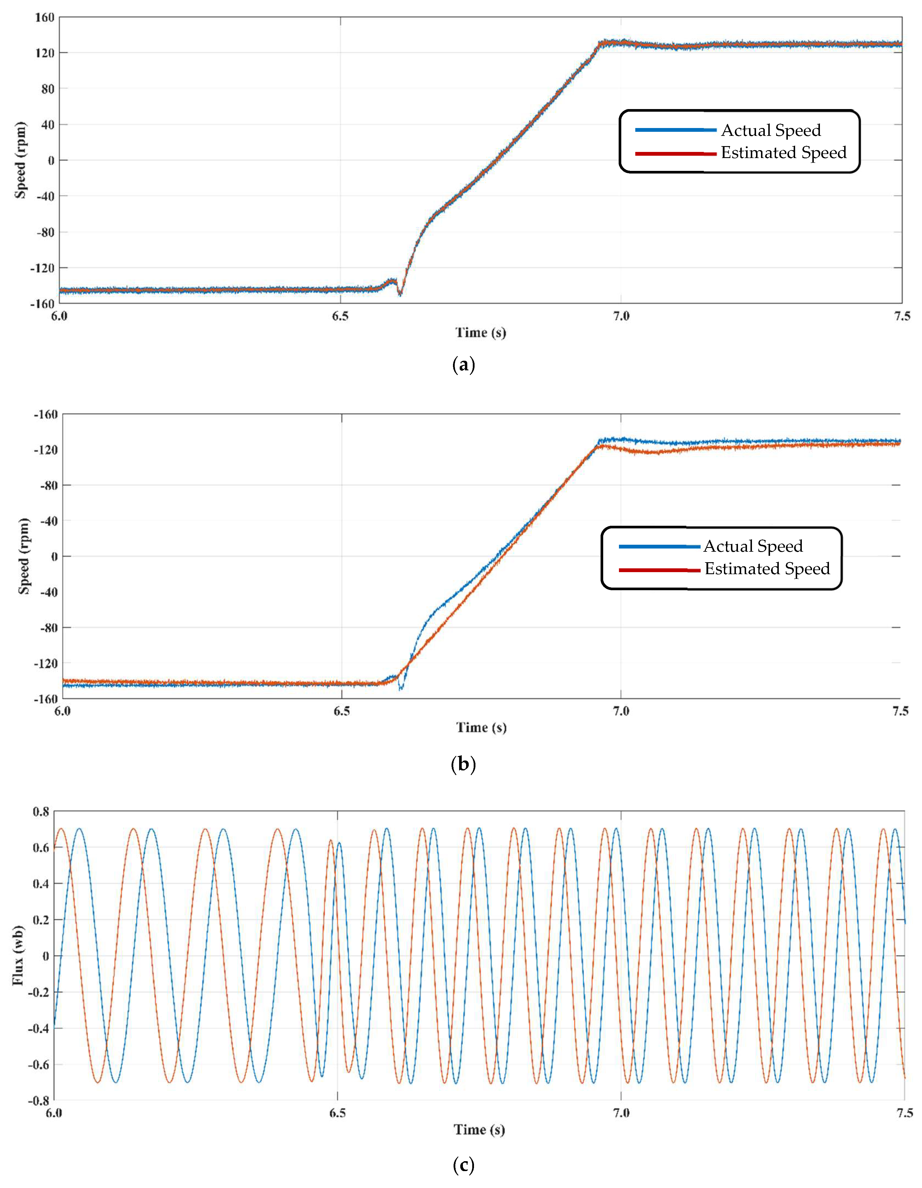
- Case 2: This scenario examines the system’s response to a predetermined reference speed, which challenges the drive’s ability to maintain field orientation at low stator frequencies. The corresponding results are illustrated in Figure 5. As depicted in Figure 5b, the standard SMO demonstrates unsteady performance, with fluctuations observed between −140 and 130 rpm. In contrast, the STSMO-based MRAS achieves stable operation without oscillations (Figure 5a).
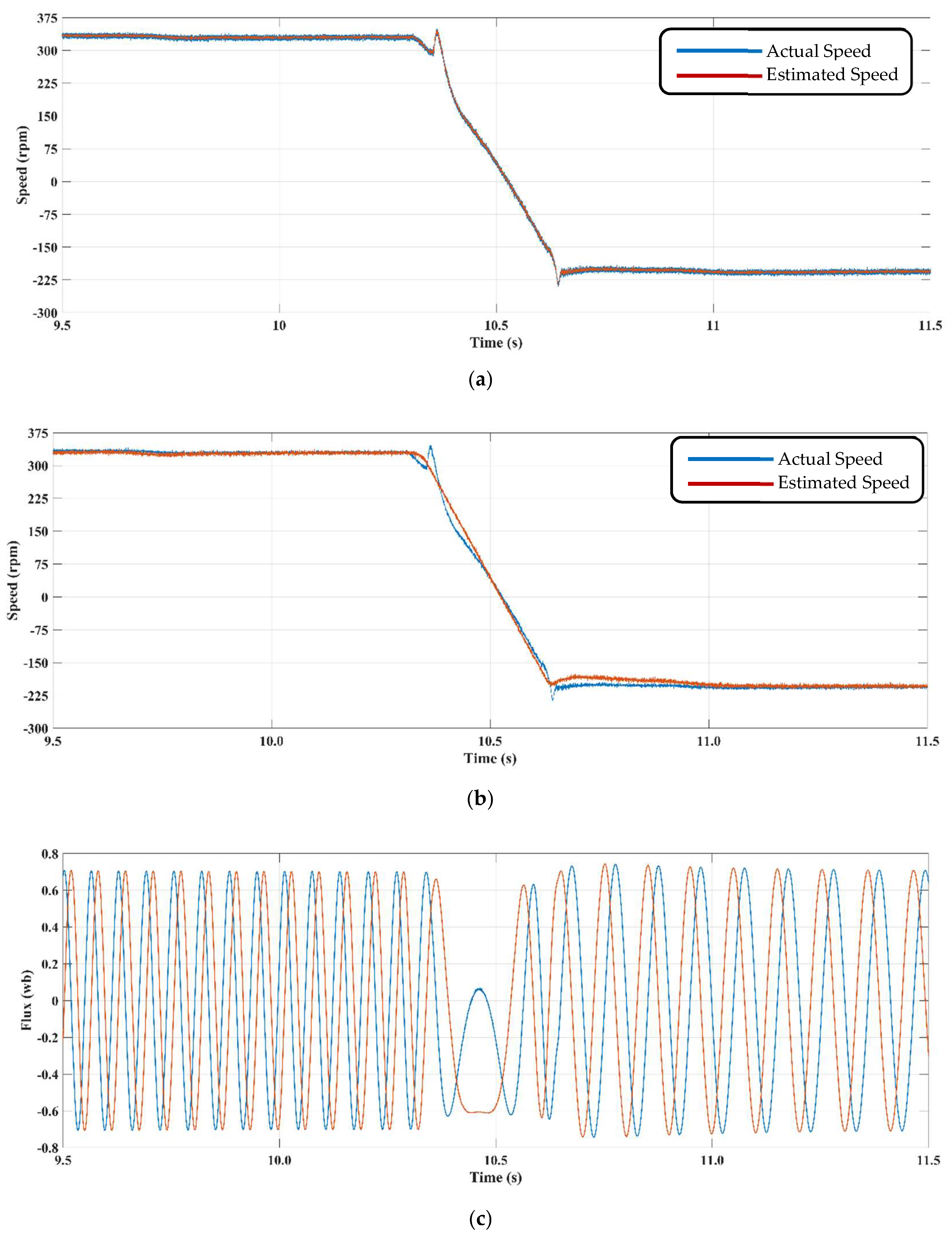
- Case 3: This scenario evaluates the encoderless drive’s performance between reference speeds of 345 rpm and −200 rpm. The results for the proposed model are depicted in Figure 6a, while Figure 6b presents the results for the traditional SMO technique. Compared to the traditional SMO with a PI controller, the proposed STSMO-based MRAS achieves consistent performance with minimal steady-state error.
4. Conclusions
- Further optimization of STSMO performance, such as adaptive tuning strategies or integration with machine-learning algorithms to enhance real-time robustness and adaptability.
- Application of the proposed STSMO to different motor control systems, including permanent magnet synchronous motors (PMSMs) and brushless DC motors (BLDCs), to explore its generalization capability across motor types.
- Hardware implementation considerations, focusing on computational efficiency and implementation on low-cost microcontrollers for industrial use cases.
Author Contributions
Funding
Institutional Review Board Statement
Informed Consent Statement
Data Availability Statement
Conflicts of Interest
References
- Prince; Hati, A.S.; Chakrabarti, P.; Abawajy, J.H.; Keong, N.W. Development of energy efficient drive for ventilation system using recurrent neural network. Neural Comput. Appl. 2021, 33, 8659–8668. [Google Scholar] [CrossRef]
- Bose, B.K. Power Electronics and AC Drives; Prentice-Hall: Englewood Cliffs, NJ, USA, 1986; 416p. [Google Scholar]
- Prince; Hati, A.S. Temperature and Humidity Dependent MRAS Based Speed Estimation Technique for Induction Motor Used in Mine Ventilation Drive. J. Min. Sci. 2021, 57, 842–851. [Google Scholar] [CrossRef]
- Kumar, P.; Hati, A.S. Sensor-less speed control of ventilation system using extended Kalman filter for high performance. In Proceedings of the 2021 IEEE 8th Uttar Pradesh Section International Conference on Electrical, Electronics and Computer Engineering (UPCON), Dehradun, India, 11–13 November 2021; IEEE: Piscataway, NJ, USA, 2021; pp. 1–6. [Google Scholar]
- Vas, P. Sensorless Vector and Direct Torque Control; Oxford University Press: Oxford, UK, 1998. [Google Scholar]
- Orlowska-Kowalska, T.; Dybkowski, M. Stator-current-based MRAS estimator for a wide range speed-sensorless induction-motor drive. IEEE Trans. Ind. Electron. 2009, 57, 1296–1308. [Google Scholar] [CrossRef]
- Ammar, A.; Bourek, A.; Benakcha, A. Sensorless SVM-direct torque control for induction motor drive using sliding mode observers. J. Control. Autom. Electr. Syst. 2017, 28, 189–202. [Google Scholar] [CrossRef]
- Wu, L.; Liu, J.; Vazquez, S.; Mazumder, S.K. Sliding mode control in power converters and drives: A review. IEEE/CAA J. Autom. Sin. 2021, 9, 392–406. [Google Scholar] [CrossRef]
- Bıçak, A.; Gelen, A. Modified Super-Twisting Algorithm-Based Model Reference Adaptive Observer for Sensorless Control of the Interior Permanent-Magnet Synchronous Motor in Electric Vehicles. Machines 2023, 11, 871. [Google Scholar] [CrossRef]
- Lu, Y.; Tan, C.; Ge, W.; Zhao, Y.; Wang, G. Adaptive disturbance observer-based improved super-twisting sliding mode control for electromagnetic direct-drive pump. Smart Mater. Struct. 2022, 32, 017001. [Google Scholar] [CrossRef]
- Yalavarthi, A.; Singh, B. SMO-based position sensorless SRM drive for battery-supported PV submersible pumps. IEEE J. Emerg. Sel. Top. Power Electron. 2021, 10, 3917–3926. [Google Scholar] [CrossRef]
- Sami, I.; Ullah, S.; Basit, A.; Ullah, N.; Ro, J.-S. Integral super twisting sliding mode based sensorless predictive torque control of induction motor. IEEE Access 2020, 8, 186740–186755. [Google Scholar] [CrossRef]
- Wang, H.; Ge, X.; Liu, Y.-C. Second-order sliding-mode MRAS observer-based sensorless vector control of linear induction motor drives for medium-low speed Maglev applications. IEEE Trans. Ind. Electron. 2018, 65, 9938–9952. [Google Scholar] [CrossRef]
- Nurettin, A.; İnanç, N. Sensorless vector control for induction motor drive at very low and zero speeds based on an adaptive-gain super-twisting sliding mode observer. IEEE J. Emerg. Sel. Top. Power Electron. 2023, 11, 4332–4339. [Google Scholar] [CrossRef]
- Lin, S.; Zhang, W. An adaptive sliding-mode observer with a tangent function-based PLL structure for position sensorless PMSM drives. Int. J. Electr. Power Energy Syst. 2017, 88, 63–74. [Google Scholar] [CrossRef]
- Yang, X.; Ge, Y.; Zhu, W.; Deng, W.; Zhao, X.; Yao, J. Adaptive Motion Control for Electro-hydraulic Servo Systems with Appointed-Time Performance. IEEE/ASME Trans. Mechatron. 2025; early access. [Google Scholar]
- Yang, X.; Deng, W.; Yao, J. Neural adaptive dynamic surface asymptotic tracking control of hydraulic manipulators with guaranteed transient performance. IEEE Trans. Neural Netw. Learn. Syst. 2022, 34, 7339–7349. [Google Scholar] [CrossRef] [PubMed]
- Bist, A.; Jadhav, S.V. Sensorless control based on sliding mode observer for pmsm drive. In Proceedings of the 2020 IEEE International Conference on Power Electronics, Drives and Energy Systems (PEDES), Jaipur, India, 16–19 December 2020; IEEE: Piscataway, NJ, USA, 2020; pp. 1–6. [Google Scholar]
- Li, Z.; Wang, J.; Wang, S.; Feng, S.; Zhu, Y.; Sun, H. Design of sensorless speed control system for permanent magnet linear synchronous motor based on fuzzy super-twisted sliding mode observer. Electronics 2022, 11, 1394. [Google Scholar] [CrossRef]
- Wang, C.; Cao, D. New sensorless speed control of a hybrid stepper motor based on fuzzy sliding mode observer. Energies 2020, 13, 4939. [Google Scholar] [CrossRef]
- Saghafinia, A.; Ping, H.W.; Uddin, M.N.; Gaeid, K.S. Adaptive fuzzy sliding-mode control into chattering-free IM drive. IEEE Trans. Ind. Appl. 2014, 51, 692–701. [Google Scholar] [CrossRef]
- Chalanga, A.; Kamal, S.; Fridman, L.M.; Bandyopadhyay, B.; Moreno, J.A. Implementation of super-twisting control: Super-twisting and higher order sliding-mode observer-based approaches. IEEE Trans. Ind. Electron. 2016, 63, 3677–3685. [Google Scholar] [CrossRef]
- Liu, Y.-C.; Laghrouche, S.; Depernet, D.; Djerdir, A.; Cirrincione, M. Disturbance-observer-based complementary sliding-mode speed control for PMSM drives: A super-twisting sliding-mode observer-based approach. IEEE J. Emerg. Sel. Top. Power Electron. 2020, 9, 5416–5428. [Google Scholar] [CrossRef]
- Nguyen, M.H.; Ahn, K.K. An improved voltage regulation performance of floating interleaved boost converters for fuel cell applications subject to input variation and load change. Appl. Sci. 2022, 12, 11501. [Google Scholar] [CrossRef]
- Wogi, L.; Morawiec, M.; Ayana, T. Sensorless Control of Induction Motor Based on Super-Twisting Sliding Mode Observer with Speed Convergence Improvement. IEEE Access 2024, 12, 74239–74250. [Google Scholar] [CrossRef]
- Huangfu, L.; Chen, C.; Zhang, T. A sensorless control scheme based on fractional order super-twisting algorithm and improved FLL for PMSM. Adv. Mech. Eng. 2024, 16, 16878132241282013. [Google Scholar] [CrossRef]
- Mishra, A.; Choudhary, P. Speed control of an induction motor by using indirect vector control method. Int. J. Emerg. Technol. Adv. Eng. 2012, 2, 144–150. [Google Scholar]
- Beerens, R.; Bisoffi, A.; Zaccarian, L.; Heemels, W.P.; Nijmeijer, H.; van de Wouw, N. Hybrid PID control for transient performance improvement of motion systems with friction. In Proceedings of the 2018 Annual American Control Conference (ACC), Milwaukee, WI, USA, 27–29 June 2018; IEEE: Piscataway, NJ, USA, 2018; pp. 539–544. [Google Scholar]
- Lascu, C.; Andreescu, G.-D. Sliding-mode observer and improved integrator with DC-offset compensation for flux estimation in sensorless-controlled induction motors. IEEE Trans. Ind. Electron. 2006, 53, 785–794. [Google Scholar] [CrossRef]
- Choudhary, M.S.; Saqi, M.S.; Javed, M.R.; Gelani, H.E. Solar powered space vector pulse width modulation based induction motor drive for industry applications. Bull. Electr. Eng. Inform. 2022, 11, 1828–1836. [Google Scholar] [CrossRef]
- Savitha, P.; Divakar, B. Performance comparison of Rotor Flux based and Back EMF Based Model Reference Adaptive System Speed Estimator for 3 Phase Induction Motor. In Proceedings of the2023 IEEE International Conference on Distributed Computing, VLSI, Electrical Circuits and Robotics (DISCOVER), Mangalore, India, 13–14 October 2023; IEEE: Piscataway, NJ, USA, 2023; pp. 127–133. [Google Scholar]


| Refs. | Proposed Method/Technique | Application/Objective | Key Contribution/Improvement |
|---|---|---|---|
| [8,9] | Alternative to PI adaptation mechanism | MRAS approaches | Improved approximation accuracy |
| [10,11] | Second-order SMO for rotor flux estimation | MRAS method | Enhanced rotor flux estimation |
| [12] | SM model-based speed observer | Magnetizing current measurement | Improved speed estimation |
| [13,14] | Fundamental SMO technique | Flux and speed estimation | Utilized SM functions for direct speed derivation |
| [15] | Enhanced SMO | IM Drives (position and velocity estimation) | Reduced chattering compared to sign function |
| [16] | Adaptive appointed-time control | Electro-hydraulic servo systems | Handles unknown parameters and disturbances |
| [17] | NN-based adaptive dynamic surface control | n-DOF hydraulic manipulators | Ensured transient performance |
| [18] | Sigmoid function-based SMO | Rotor position estimation in IMs | Reduced chattering |
| [19,20,21] | Fuzzy-logic-based SMO | Flux and speed estimation | Mitigated chattering, improved load distortion resilience |
| [22] | Super-twisting observer (STO) with SMC | Slide mode control | Discussed limitations of SOSM |
| [23] | DO-CSM speed controller | FOC-PMSM drive system | Disturbance-observer-based control |
| [24] | Control framework for FIBCs | Fuel cell application | Precise output voltage regulation |
| Gain Value | RMSE | Convergence Time | Chattering Index |
|---|---|---|---|
| 500 | 1.12 | 120 | high |
| 1000 | 0.35 | 65 | Very-low |
| 1500 | 0.42 | 75 | low |
| 2000 | 0.56 | 90 | moderate |
| Observer | Complexity | Robustness | Maximum Estimation Error | |
|---|---|---|---|---|
| 1 | PWM method [30] | High | Low | Occurs at medium and high speeds |
| 2 | Back-EMF-based method [31] | Low | High | Occurs at medium and high speeds |
| 3 | MRAS-based method [6] | Low | High | Occurs at low and medium speeds |
| 4 | SMO-based method [7] | Moderate | Moderate | Occurs at medium and high speeds |
| 5 | Proposed method | Low | High | Occurs at low and medium speeds |
| Response | Conventional SMO | Proposed Controller | |
|---|---|---|---|
| Speed Response | Rise time (ms) | 80 | 15 |
| Settling time (ms) | 450 | 100 | |
| Overshoot time (/min) | 50 | 0 | |
| Observer | Spectral Entropy | HF Energy (1–10 kHz) | RMSE Chattering (rad/s) |
|---|---|---|---|
| SMO | 0.72 | 2.84 × 10⁻² | 0.094 |
| MRAS | 0.66 | 2.14 × 10⁻² | 0.071 |
| Proposed method | 0.45 | 6.75 × 10⁻³ | 0.023 |
Disclaimer/Publisher’s Note: The statements, opinions and data contained in all publications are solely those of the individual author(s) and contributor(s) and not of MDPI and/or the editor(s). MDPI and/or the editor(s) disclaim responsibility for any injury to people or property resulting from any ideas, methods, instructions or products referred to in the content. |
© 2025 by the authors. Licensee MDPI, Basel, Switzerland. This article is an open access article distributed under the terms and conditions of the Creative Commons Attribution (CC BY) license (https://creativecommons.org/licenses/by/4.0/).
Share and Cite
Prince; Yoon, B. Super Twisted Sliding Mode Observer for Enhancing Ventilation Drive Performance. Appl. Sci. 2025, 15, 4927. https://doi.org/10.3390/app15094927
Prince, Yoon B. Super Twisted Sliding Mode Observer for Enhancing Ventilation Drive Performance. Applied Sciences. 2025; 15(9):4927. https://doi.org/10.3390/app15094927
Chicago/Turabian StylePrince, and Byungun Yoon. 2025. "Super Twisted Sliding Mode Observer for Enhancing Ventilation Drive Performance" Applied Sciences 15, no. 9: 4927. https://doi.org/10.3390/app15094927
APA StylePrince, & Yoon, B. (2025). Super Twisted Sliding Mode Observer for Enhancing Ventilation Drive Performance. Applied Sciences, 15(9), 4927. https://doi.org/10.3390/app15094927