
A Low-Profile Dual-Polarized Transmitarray with Enhanced Gain and Beam Steering at Ku Band

 , , ,
, , ,  and
and 
Abstract
1. Introduction
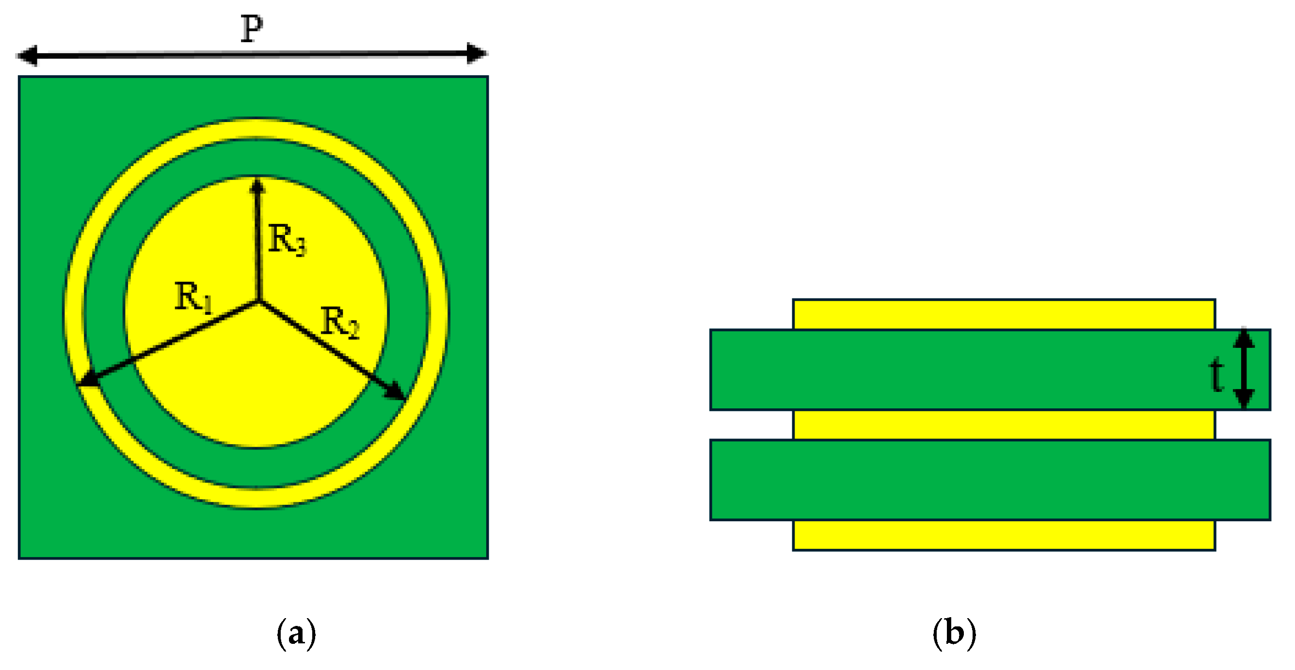
2. UC Design
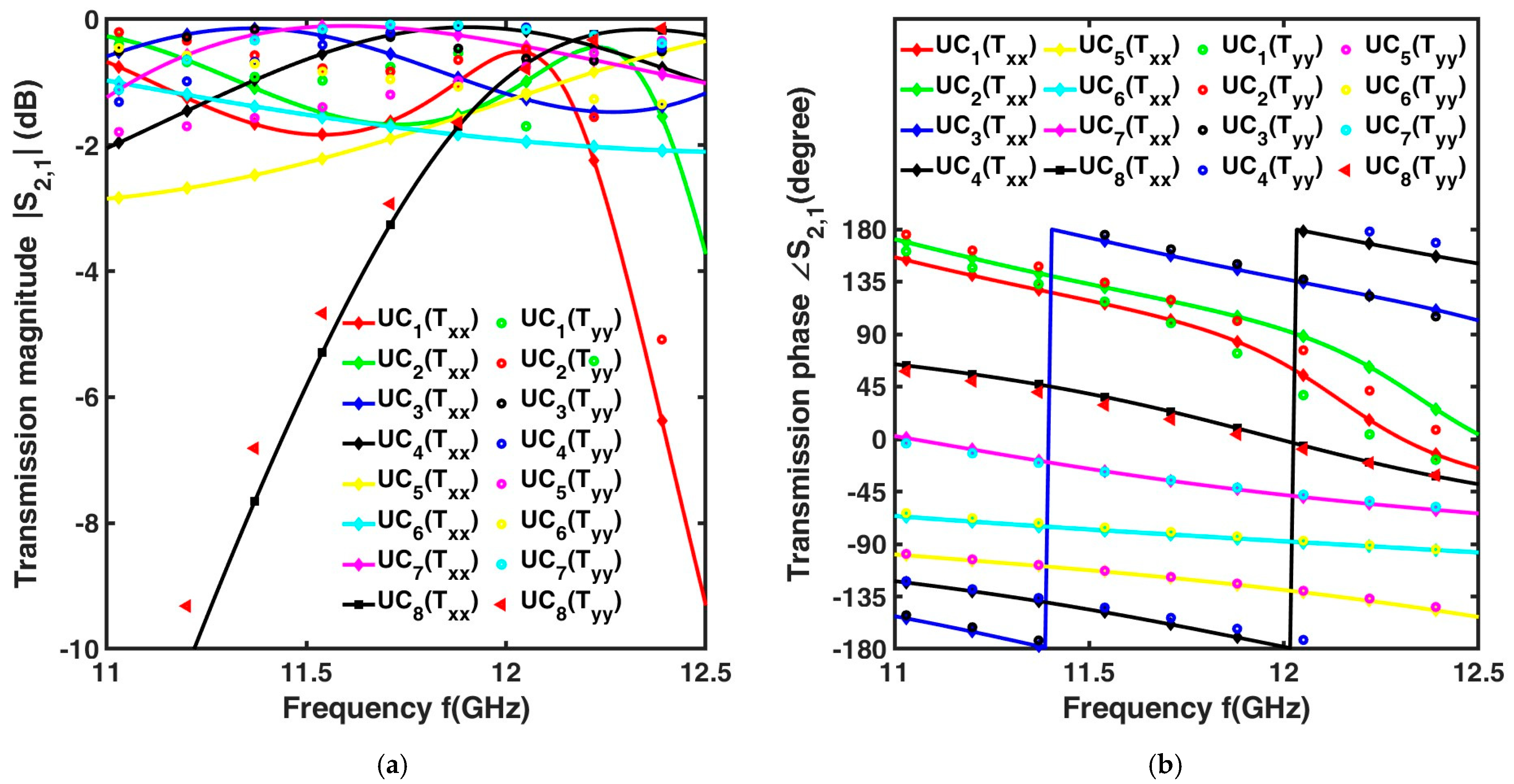
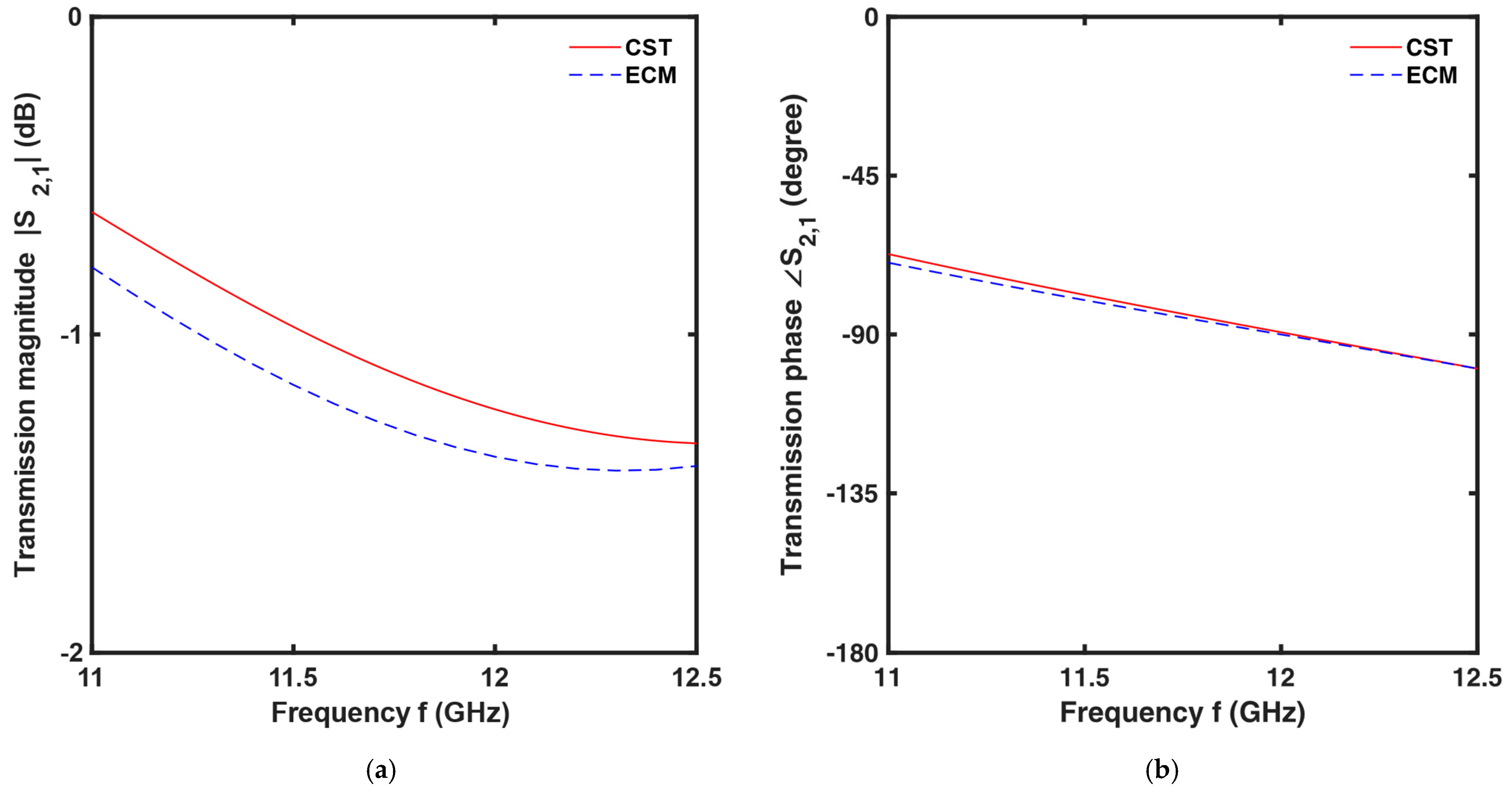
3. Equivalent Circuit Analysis of the UC
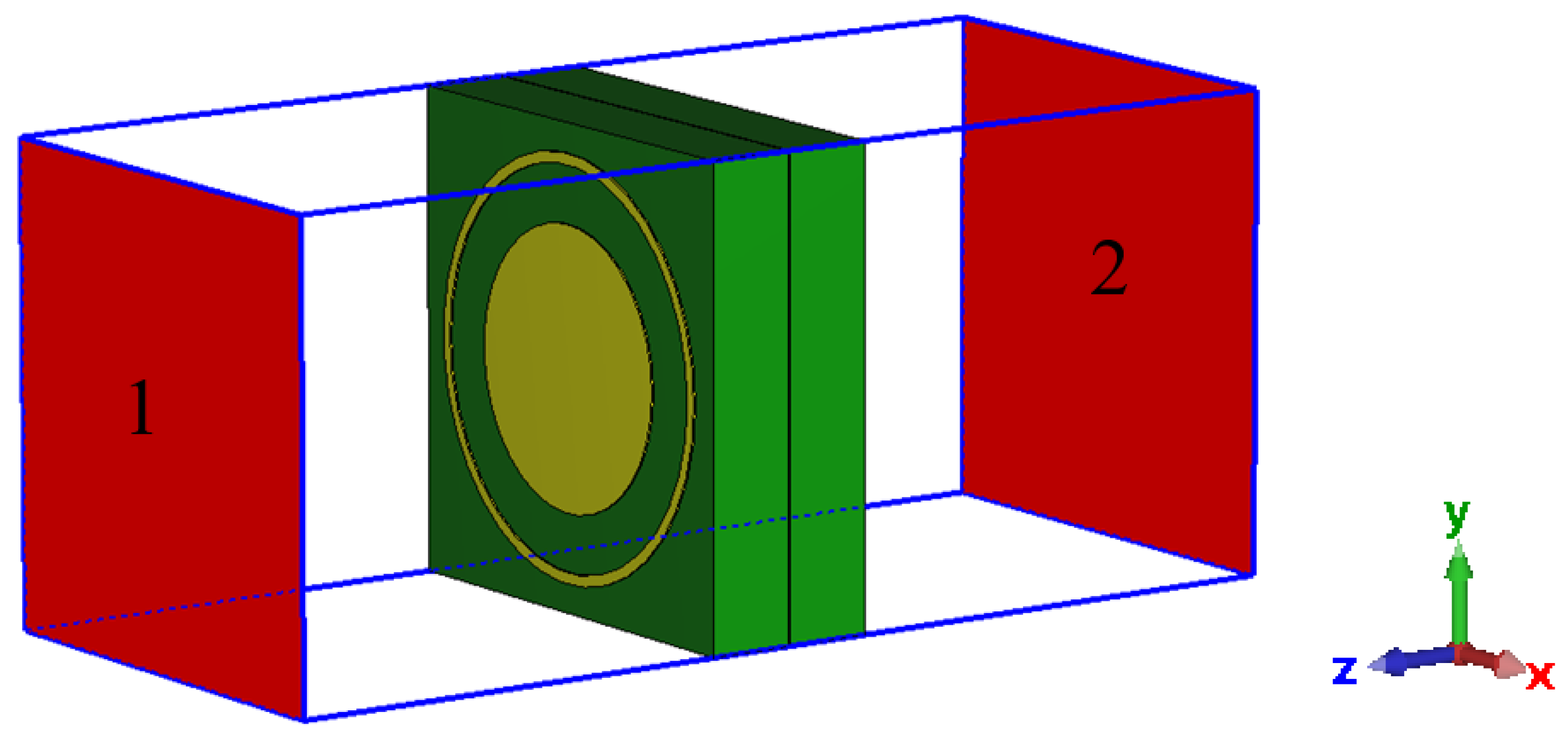
4. The TA Antenna
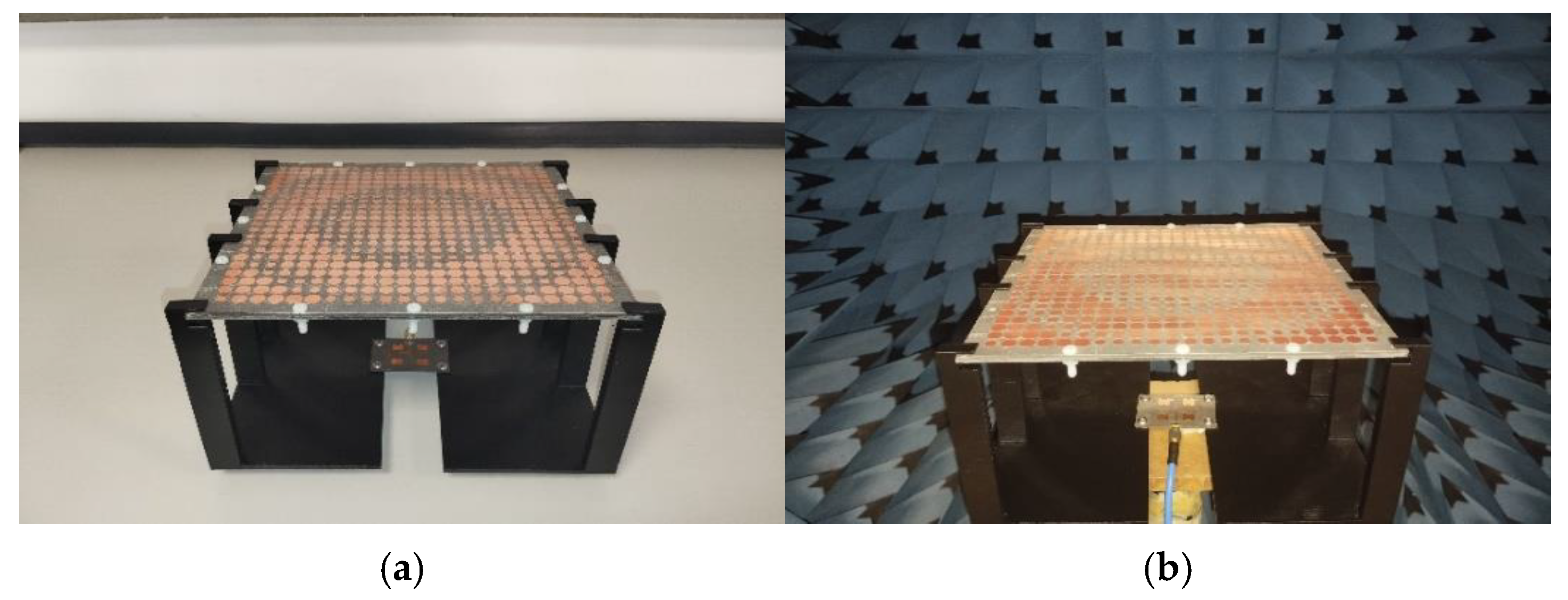
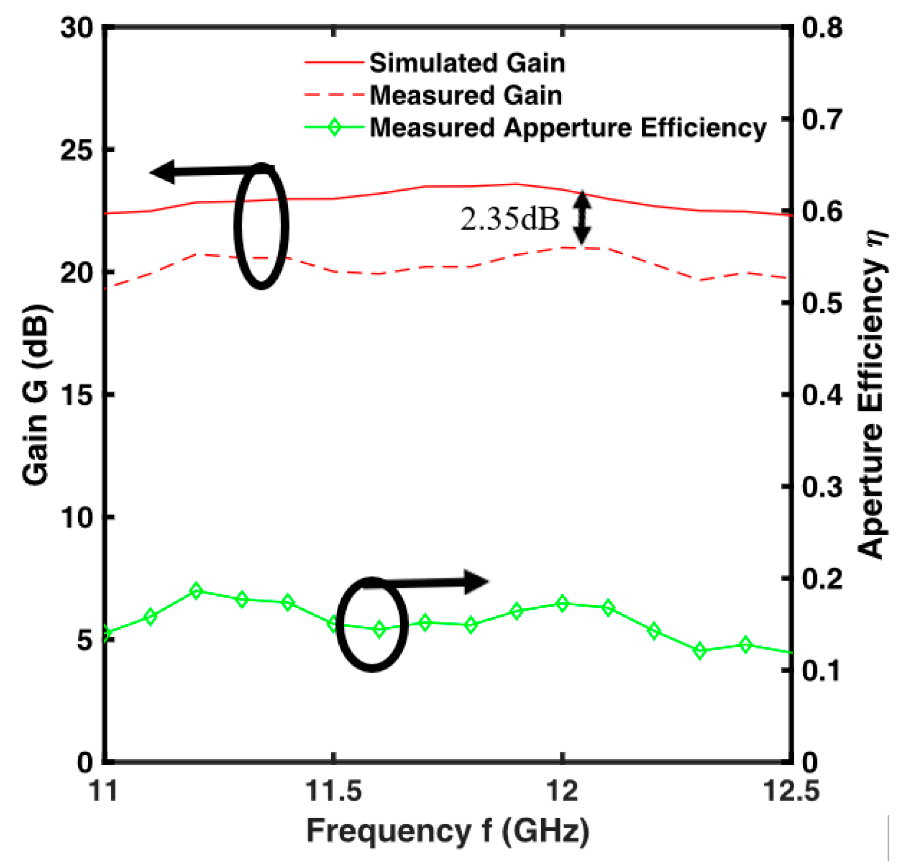
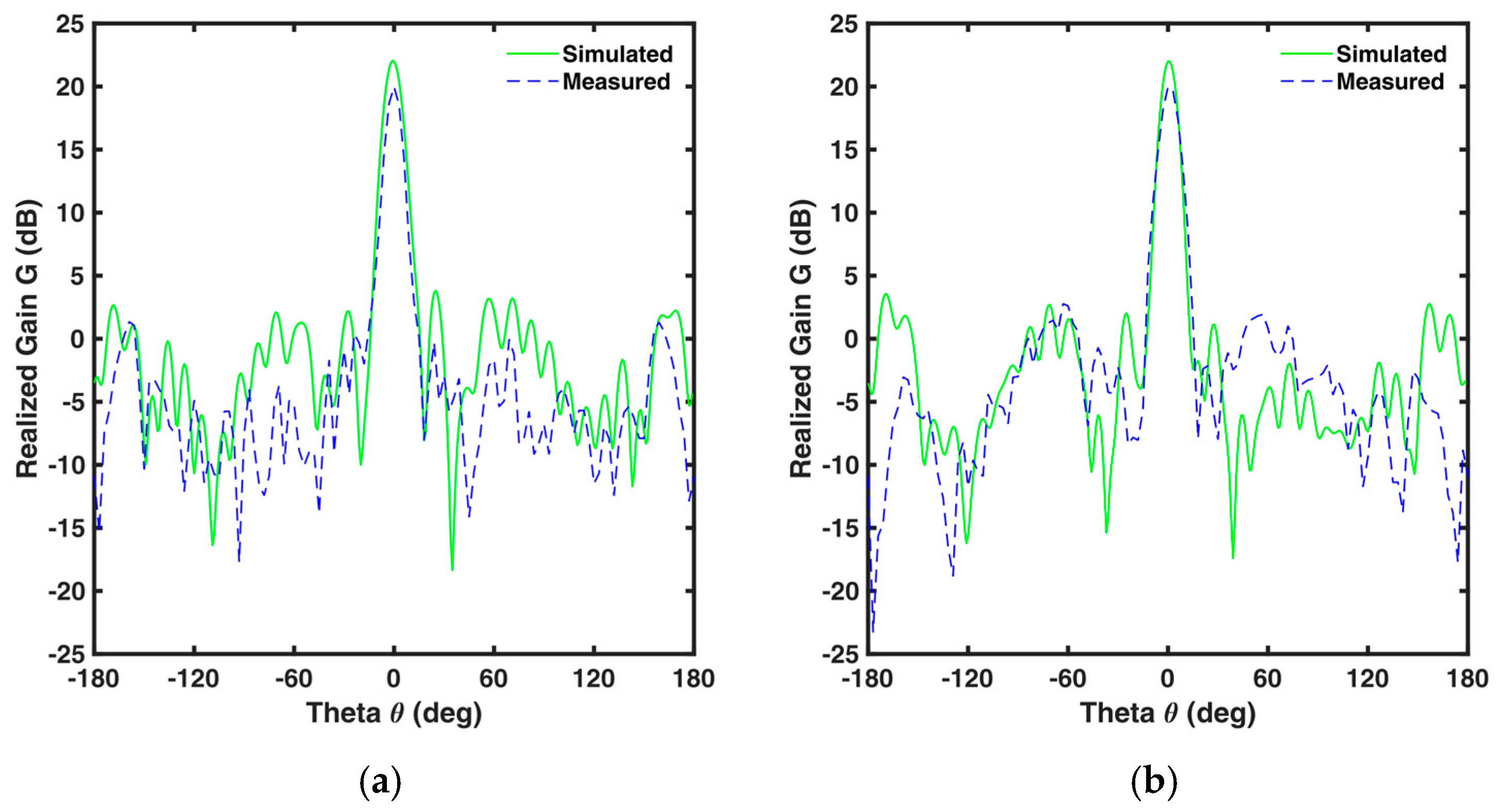
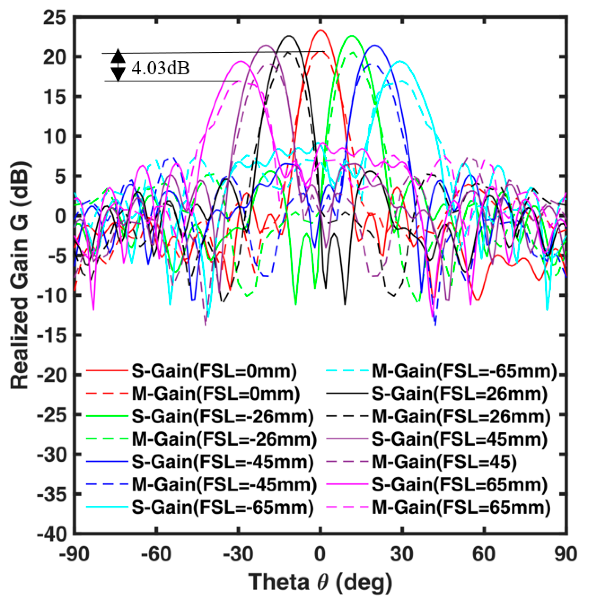
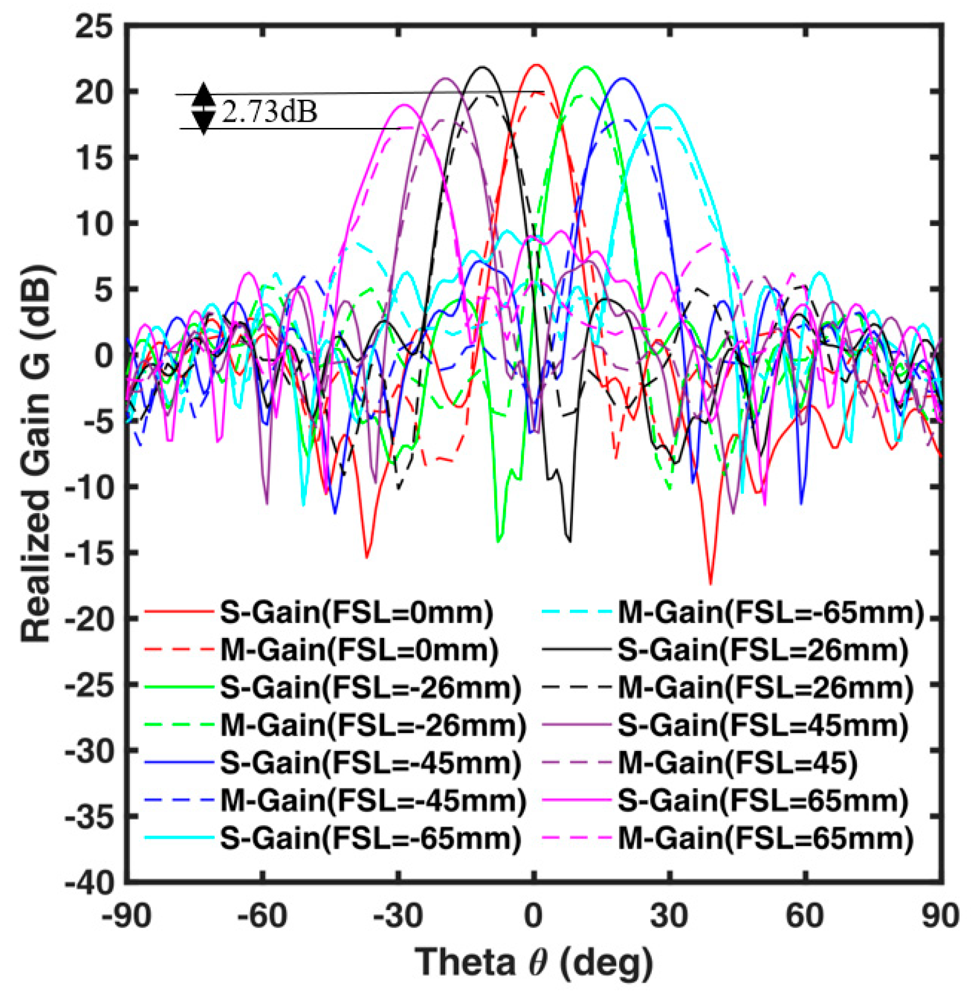
5. Simulation and Experimental Results of the TA Antenna
6. Comparison with Other Works
7. Conclusions
Author Contributions
Funding
Institutional Review Board Statement
Informed Consent Statement
Data Availability Statement
Conflicts of Interest
Abbreviations
| TA | Transmitarray |
| UC | Unit cell |
| ECM | Equivalent circuit model |
References
- Alhalabi, R.A.; Rebeiz, G.M. High-efficiency angled-dipole antennas for millimeter-wave phased array applications. IEEE Trans. Antennas Propag. 2008, 56, 3136–3142. [Google Scholar] [CrossRef]
- Zhang, H.Y.; Zhang, F.S.; Zhang, F.; Sun, F.K.; Xie, G.J. High-power array antenna based on phase-adjustable array element for wireless power transmission. IEEE Antennas Wirel. Propag. Lett. 2017, 16, 2249–2253. [Google Scholar] [CrossRef]
- Zhang, S.; Chen, X.; Syrytsin, I.; Pedersen, G.F. A planar switchable 3-D-coverage phased array antenna and its user effects for 28-GHz mobile terminal applications. IEEE Trans. Antennas Propag. 2017, 65, 6413–6421. [Google Scholar] [CrossRef]
- Han, G.; Du, B.; Wu, W.; Yang, B. A novel hybrid phased array antenna for satellite communication on-the-move in Ku-band. IEEE Trans. Antennas Propag. 2015, 63, 1375–1383. [Google Scholar] [CrossRef]
- Wang, Z.; Zhang, G.X.; Yin, Y.; Wu, J. Design of a dual-band high-gain antenna array for WLAN and WiMAX base station. IEEE Antennas Wirel. Propag. Lett. 2014, 13, 1721–1724. [Google Scholar] [CrossRef]
- Alotaibi, N.N.; Hamdi, K.A. Switched phased-array transmission architecture for secure millimeter-wave wireless communication. IEEE Trans. Commun. 2016, 64, 1303–1312. [Google Scholar] [CrossRef]
- Hwang, S.; Lee, B.; Kim, D.H.; Park, J.Y. Design of S-band phased array antenna with high isolation using broadside coupled split ring resonator. J. Electromagn. Eng. Sci. 2018, 18, 108–116. [Google Scholar] [CrossRef]
- Xu, H.X.; Cai, T.; Zhuang, Y.Q.; Peng, Q.; Wang, G.; Liang, J.G. Dual-mode transmissive metasurface and its applications in multibeam transmitarray. IEEE Trans. Antennas Propag. 2017, 65, 1797–1806. [Google Scholar] [CrossRef]
- Diaby, F.; Clemente, A.; Sauleau, R.; Pham, K.T.; Dussopt, L. 2-bit reconfigurable unit-cell and electronically steerable transmitarray at Ka-band. IEEE Trans. Antennas Propag. 2020, 68, 5003–5008. [Google Scholar] [CrossRef]
- Wang, Y.; Xu, S.; Yang, F.; Li, M. A novel 1-bit wide-angle beam scanning reconfigurable transmitarray antenna using an equivalent magnetic dipole element. IEEE Trans. Antennas Propag. 2020, 68, 5691–5695. [Google Scholar] [CrossRef]
- Zeng, Q.; Xue, Z.; Ren, W.; Li, W. Dual-band beam-scanning antenna using rotatable planar phase gradient transmitarrays. IEEE Trans. Antennas Propag. 2020, 68, 5021–5026. [Google Scholar] [CrossRef]
- Liang, Z.; Ouyang, J.; Yang, F. Low-profile wideband circularly polarised single-layer metasurface antenna. Electron. Lett. 2018, 54, 1362–1364. [Google Scholar] [CrossRef]
- Abdelrahman, A.H.; Nayeri, P.; Elsherbeni, A.Z.; Yang, F. Single-feed quad-beam transmitarray antenna design. IEEE Trans. Antennas Propag. 2016, 64, 953–959. [Google Scholar] [CrossRef]
- Zheng, B.; Fan, Y.; Cheng, Y.J. Wideband high-efficiency circularly polarized transmitarray with linearly polarized feed. IEEE Antennas Wirel. Propag. Lett. 2023, 22, 1451–1455. [Google Scholar] [CrossRef]
- Abdelrahman, A.H.; Yang, F.; Elsherbeni, A.Z.; Nayeri, P.; Balanis, C.A. Analysis and Design of Transmitarray Antennas; Springer: Cham, Switzerland, 2017; pp. 1–151. [Google Scholar]
- Ramazannia Tuloti, S.H.; Rezaei, P.; Tavakkol Hamedani, F. High-efficient wideband transmitarray antenna. IEEE Antennas Wirel. Propag. Lett. 2018, 17, 817–820. [Google Scholar] [CrossRef]
- Watts, C.M.; Pedross-Engel, A.; Smith, D.R.; Reynolds, M.S. X-band SAR imaging with a liquid-crystal-based dynamic metasurface antenna. J. Opt. Soc. Am. B Opt. Phys. 2017, 34, 300–306. [Google Scholar] [CrossRef]
- Arbabi, E.; Arbabi, A.; Kamali, S.M.; Horie, Y.; Faraji-Dana, M.; Faraon, A. MEMS-tunable dielectric metasurface lens. Nat. Commun. 2018, 9, 812. [Google Scholar] [CrossRef] [PubMed]
- Sleasman, T.; Imani, M.F.; Xu, W.; Hunt, J.; Driscoll, T.; Reynolds, M.S.; Smith, D.R. Waveguide-fed tunable metamaterial element for dynamic apertures. IEEE Antennas Wirel. Propag. Lett. 2016, 15, 606–609. [Google Scholar] [CrossRef]
- Xu, H.-X.; Tang, S.; Ma, S.; Luo, W.; Cai, T.; Sun, S.; He, Q.; Zhou, L. Tunable microwave metasurfaces for high-performance operations: Dispersion compensation and dynamical switch. Sci. Rep. 2016, 6, 38255. [Google Scholar] [CrossRef]
- Massaccesi, A.; Dassano, G.; Pirinoli, P. Beam scanning capabilities of a 3D-printed perforated dielectric transmitarray. Electronics 2019, 8, 379. [Google Scholar] [CrossRef]
- Ali, Q.; Shahzad, W.; Ahmad, I.; Safiq, S.; Bin, X.; Abbas, S.M.; Sun, H. Recent developments and challenges on beam steering characteristics of reconfigurable transmitarray antennas. Electronics 2022, 11, 587. [Google Scholar] [CrossRef]
- Lee, J.-G.; Kwon, T.-S.; Lee, J.-H. Beam pattern reconfigurable circularly polarized transmitarray antenna by rearrangement of sources. Microw. Opt. Technol. Lett. 2019, 61, 999–1003. [Google Scholar] [CrossRef]
- Lee, C.; Hoang, T.V.; Wook, S.; Lee, S.; Lee, J. Low-profile quad-beam circularly polarised antenna using transmissive metasurface. IET Microw. Antennas Propag. 2019, 13, 1690–1698. [Google Scholar] [CrossRef]
- Mei, P.; Zhang, S.; Pedersen, G.F. A low-profile and beam-steerable transmitarray antenna: Design, fabrication, and measurement [Antenna Applications Corner]. IEEE Antennas Propag. Mag. 2021, 63, 88–101. [Google Scholar] [CrossRef]
- De Marco, R.; Arnieri, E.; Greco, F.; Bordbar, A.; Amendola, G.; Boccia, L. Low-profile dual-band dual-polarized transmitarray antenna based on multilayer frequency selective surfaces. IEEE Trans. Antennas Propag. 2023, 71, 7354–7362. [Google Scholar] [CrossRef]
- Jiao, X.-H.; Wan, G. A novel low-profile planar microstrip transmitarray antenna with high efficiency. Int. J. RF Microw. Comput.-Aided Eng. 2021, 31, e22614. [Google Scholar] [CrossRef]
- Park, J.-H.; Lee, J.-G. Low-profile high-efficiency transmitarray antenna using optimized phase compensation surface (PCS) and PEC sidewalls. ICT Express 2021, 7, 501–506. [Google Scholar] [CrossRef]
- Frank, M.; Lurz, F.; Weigel, R.; Koelpin, A. Low-profile and low-cost transmitarray antenna at 122 GHz based on unit-cells with 1-bit phase resolution. Electron. Lett. 2020, 56, 1293–1295. [Google Scholar] [CrossRef]
- Wang, X.; Cheng, Y.; Dong, Y. Millimeter-wave high-efficiency double-layer transmitarray antenna using miniaturized dual-polarized elements. IEEE Trans. Antennas Propag. 2022, 70, 8637–8642. [Google Scholar] [CrossRef]
- Li, T.; Sun, J.; Meng, H.; Shen, Y.; Hu, S.; Dou, W.; Chen, Z.N.; Zwick, T. Characteristic mode inspired dual-polarized double-layer metasurface lens. IEEE Trans. Antennas Propag. 2021, 69, 3144–3154. [Google Scholar] [CrossRef]
- Xue, C.; Sun, J.; Niu, L.; Lou, Q. Ultrathin dual-polarized Huygens’ metasurface: Design and application. Ann. Phys. 2020, 532, 2000151. [Google Scholar] [CrossRef]
- Yang, S.; Yan, Z.; Cai, M.; Fan, F.; Zhang, T. A high-efficiency double-layer transmitarray antenna using low-loss dual-linearly polarized elements. IEEE Antennas Wirel. Propag. Lett. 2020, 19, 2378–2382. [Google Scholar] [CrossRef]
- Yi, X.; Su, T.; Li, X.; Wu, B.; Yang, L. A double-layer wideband transmitarray antenna using two degrees of freedom elements around 20 GHz. IEEE Trans. Antennas Propag. 2019, 67, 2798–2802. [Google Scholar] [CrossRef]
- Pham, K.; Nguyen, N.T.; Clemente, A.; Di Palma, L.; Le Coq, L.; Dussopt, L.; Sauleau, R. Design of wideband dual linearly polarized transmitarray antennas. IEEE Trans. Antennas Propag. 2016, 64, 2022–2026. [Google Scholar] [CrossRef]
- Aziz, A.; Yang, F.; Xu, S.; Li, M. An efficient dual-band orthogonally polarized transmitarray design using three-dipole elements. IEEE Antennas Wirel. Propag. Lett. 2018, 17, 319–322. [Google Scholar] [CrossRef]
- Bagheri, M.O.; Hassani, H.R.; Rahmati, B. Dual-band, dual-polarised metallic slot transmitarray antenna. IET Microw. Antennas Propag. 2017, 11, 402–409. [Google Scholar] [CrossRef]
- Aziz, A.; Yang, F.; Xu, S.; Li, M.; Chen, H.-T. A high-gain dual-band and dual-polarized transmitarray using novel loop elements. IEEE Antennas Wirel. Propag. Lett. 2019, 18, 1213–1217. [Google Scholar] [CrossRef]
- Wu, F.; Wang, J.; Xiang, L.; Hong, W.; Luk, K.-M. A wideband dual-polarized magneto-electric dipole transmitarray with independent control of polarizations. IEEE Trans. Antennas Propag. 2022, 70, 8632–8636. [Google Scholar] [CrossRef]
- Pham, K.T.; Sauleau, R.; Fourn, E.; Diaby, F.; Clemente, A.; Dussopt, L. Dual-band transmitarrays with dual-linear polarization at Ka-band. IEEE Trans. Antennas Propag. 2017, 65, 7009–7018. [Google Scholar] [CrossRef]
- Pan, W.; Huang, C.; Ma, X.; Jiang, B.; Luo, X. A dual linearly polarized transmitarray element with 1-bit phase resolution in X-band. IEEE Antennas Wirel. Propag. Lett. 2015, 14, 167–170. [Google Scholar] [CrossRef]
- Saleh, W.; Letestu, Y.; Sauleau, R.; Cruz, E.M. Design and measurements of a high-performance wideband transmitarray antenna for D-band communications. IEEE Antennas Wirel. Propag. Lett. 2021, 20, 1765–1769. [Google Scholar] [CrossRef]
- Wang, Y.; Xu, S.; Yang, F.; Werner, D.H. 1-bit dual-linear polarized reconfigurable transmitarray antenna using asymmetric dipole elements with parasitic bypass dipoles. IEEE Trans. Antennas Propag. 2021, 69, 1188–1192. [Google Scholar] [CrossRef]
- Zhang, S.; Cao, W.; Wu, T.; Wang, J.; Wei, Y. The Design of a Multifunctional Coding Transmitarray with Independent Manipulation of the Polarization States. Micromachines 2024, 15, 1014. [Google Scholar] [CrossRef] [PubMed]
- Li, Z.; Weng, X.; Yi, X.; Li, K.; Duan, W.; Bi, M. Design and analysis of a complementary structure-based high selectivity tri-band frequency selective surface. Sci. Rep. 2024, 14, 9415. [Google Scholar] [CrossRef]
- Losito, O.; Portosi, V.; Venanzoni, G.; Bigelli, F.; Mencarelli, D.; Scalmati, P.; Renghini, C.; Carta, P.; Prudenzano, F. Feasibility investigation of SIW cavity-backed patch antenna array for Ku-band applications. Appl. Sci. 2019, 9, 1271. [Google Scholar] [CrossRef]
- Huang, G.-L.; Pang, Z.-Y.; Al-Nuaimi, M.K.T.; Kishk, A.A.; Mahmoud, A. A Broadband and High-Aperture-Efficiency Multilayer Transmitarray Based on Aperture-Coupled Slot Unit Cells. IEEE Trans. Antennas Propag. 2023, 71, 9633–9642. [Google Scholar] [CrossRef]
- Fan, Y.-L.; Lin, X.-Q.; Liu, S.-L. A broadband bifocal conformal transmitarray antenna with wide scanning angles. Microw. Opt. Technol. Lett. 2022, 64, 1800–1808. [Google Scholar] [CrossRef]
- Jiang, M.; Chen, Z.N.; Zhang, Y.; Hong, W.; Xuan, X. Metamaterial-based thin planar lens antenna for spatial beamforming and multibeam massive MIMO. IEEE Trans. Antennas Propag. 2017, 65, 464–472. [Google Scholar] [CrossRef]
- Zhang, F.; Yang, G.-M.; Jin, Y.-Q. Low-Profile Circularly Polarized Transmitarray for Wide-Angle Beam Control With a Third-Order Meta-FSS. IEEE Trans. Antennas Propag. 2020, 68, 3586–3597. [Google Scholar] [CrossRef]
- Niroo Jazi, M.; Chaharmir, M.R.; Shaker, J.; Sebak, A.R. Broadband transmitarray antenna design using polarization-insensitive frequency selective surfaces. IEEE Trans. Antennas Propag. 2016, 64, 99–108. [Google Scholar] [CrossRef]
- Li, M.-Y.; Ban, Y.-L.; Yan, F.-Q. Wideband low-profile Ku-band transmitarray antenna. IEEE Access 2021, 9, 6683–6688. [Google Scholar] [CrossRef]
- Li, G.; Ge, Y.; Chen, Z. A compact multibeam folded transmitarray antenna at Ku-band. IEEE Antennas Wirel. Propag. Lett. 2021, 20, 808–812. [Google Scholar] [CrossRef]


| Parameters | Value (mm) |
|---|---|
| P | 8.65 |
| R1 | 3.8–4.325 |
| R2 | 3.7–4.225 |
| R3 | 2.55–4.11 |
| T | 1.575 |
| UC No. | R1 (mm) | R2 (mm) | R3 (mm) | |S2,1| (dB) | ∠S2,1 (deg) |
|---|---|---|---|---|---|
| 1 | 4.325 | 4.225 | 4.11 | −0.86 | 46 |
| 2 | 4.325 | 4.225 | 4.07 | −0.58 | 89 |
| 3 | 4.325 | 4.225 | 3.96 | −0.92 | 136 |
| 4 | 4.20 | 4.10 | 3.83 | −0.20 | 179.3 |
| 5 | 4.25 | 4.15 | 3.60 | −0.71 | 225 |
| 6 | 4.325 | 4.20 | 3.07 | −1.23 | 270.6 |
| 7 | 4.20 | 4.10 | 2.63 | −0.17 | 314 |
| 8 | 3.80 | 3.70 | 2.55 | −1.16 | 359.6 |
| Parameters | Value |
|---|---|
| C0 | 0.323 pF |
| Cg | 0.042 pF |
| C1 | 0.019 pF |
| Lr | 3.727 nH |
| Lc | 1.729 nH |
| Ref. | Jiang et al., 2017 [49] | Zhang et al., 2020 [50] | Niroo Jazi et al., 2016 [51] | Li et al., 2021 [52] | Li et al., 2021 [53] | This Work | |
|---|---|---|---|---|---|---|---|
| Frequency f (GHz) | 27.5 | 10 | 12 | 15 | 12.5 | 12 | 12.4 |
| No. of layers | 2 | 3 | 5 | 3 | 3 | 3 | 3 |
| Thickness ρ (λ0) | 0.18 | 0.133 | 0.582 | 0.165 | 0.083 | 0.126 | 0.13 |
| Array size A (λ02) | 86.06 | 16.0 | 64.0 | 38.48 | 90.9 | 57.9 | 62.35 |
| Gain G (dB) | 24.2 | 19.3 | 23.0 | 23.06 | 22.7 | 21.0 | 19.97 |
| Scan range γmax (degree) | ±27 | +60 | ±35 | ±30 | ±21 | ±30 | ±30 |
| Scan loss △G (dB) | 3.7 | 4.15 | 3.0 | 3.6 | 2.7 | 4.03 | 2.73 |
| F/D | 0.50 | 0.60 | 0.78 | 0.75 | 0.59 | 0.60 | 0.60 |
| Polarization | Dual LP | Single CP | Ins. * | Dual LP and Dual CP | Single LP | Dual LP | Dual LP |
| Side Lobe Level SLL (dB) | −18.4 | −17.7 | −15.0 | −35.0 | −15.0 | −20.8 | −18.5 |
| Phase states | 240° | 180° | 360° | 360° | 360° | 360° | 360° |
| Air gap | Yes | No | No | Yes | No | No | No |
| Aperture Efficiency η (%) | 24.5 | 40.2 | 34.64 | 42.3 | 15.2 | 17.0 | 13.0 |
Disclaimer/Publisher’s Note: The statements, opinions and data contained in all publications are solely those of the individual author(s) and contributor(s) and not of MDPI and/or the editor(s). MDPI and/or the editor(s) disclaim responsibility for any injury to people or property resulting from any ideas, methods, instructions or products referred to in the content. |
© 2025 by the authors. Licensee MDPI, Basel, Switzerland. This article is an open access article distributed under the terms and conditions of the Creative Commons Attribution (CC BY) license (https://creativecommons.org/licenses/by/4.0/).
Share and Cite
Khan, M.I.; Loconsole, A.M.; Anelli, F.; Francione, V.V.; Khan, A.U.; Simone, M.; Sorbello, G.; Prudenzano, F. A Low-Profile Dual-Polarized Transmitarray with Enhanced Gain and Beam Steering at Ku Band. Appl. Sci. 2025, 15, 4656. https://doi.org/10.3390/app15094656
Khan MI, Loconsole AM, Anelli F, Francione VV, Khan AU, Simone M, Sorbello G, Prudenzano F. A Low-Profile Dual-Polarized Transmitarray with Enhanced Gain and Beam Steering at Ku Band. Applied Sciences. 2025; 15(9):4656. https://doi.org/10.3390/app15094656
Chicago/Turabian StyleKhan, Md. Imran, Antonella Maria Loconsole, Francesco Anelli, Vito Vincenzo Francione, Ahsan Ullah Khan, Marco Simone, Gino Sorbello, and Francesco Prudenzano. 2025. "A Low-Profile Dual-Polarized Transmitarray with Enhanced Gain and Beam Steering at Ku Band" Applied Sciences 15, no. 9: 4656. https://doi.org/10.3390/app15094656
APA StyleKhan, M. I., Loconsole, A. M., Anelli, F., Francione, V. V., Khan, A. U., Simone, M., Sorbello, G., & Prudenzano, F. (2025). A Low-Profile Dual-Polarized Transmitarray with Enhanced Gain and Beam Steering at Ku Band. Applied Sciences, 15(9), 4656. https://doi.org/10.3390/app15094656