Article

Evaluating the Reliability of Powder Bed Fusion for Biomedical Materials: An Experimental Approach

by
Danut Vasile Leordean
1,*,
Cosmin Cosma
1,
Nicolae Balc
1 and
Mircea Cristian Dudescu
2,*
1
Department of Manufacturing Engineering, Faculty of Industrial Engineering, Robotics and Production Management, Technical University of Cluj-Napoca, Memorandumului 28, 400114 Cluj-Napoca, Romania
2
Department of Mechanical Engineering, Faculty of Automotive, Mechatronics and Mechanical Engineering, Technical University of Cluj-Napoca, Memorandumului 28, 400114 Cluj-Napoca, Romania
*
Authors to whom correspondence should be addressed.
Appl. Sci. 2025, 15(8), 4542; https://doi.org/10.3390/app15084542
Submission received: 2 March 2025 / Revised: 9 April 2025 / Accepted: 10 April 2025 / Published: 20 April 2025

Abstract

:
This article provides a comprehensive, step-by-step framework that bridges the gap between the theory and engineering practical applications of Powder Bed Fusion (PBF) technology for producing high-quality metal parts suitable for end users. This proposed framework integrates multiple aspects into a coherent methodology on how to evaluate the PBF parameters and processing conditions, in order to establish a reliability scale for the PBF process on the Realizer 250 SLM machine. Experimental research, conducted over the past 10 years, reveals that the PBF process often encounters challenges related to process stability and part consistency. To address these issues, this paper introduces a novel method for evaluating the manufacturing process by considering the obtained physico-mechanical characteristics. The determined properties of PBF samples were ultimate tensile strength, Young’s modulus, the Poisson ratio, maximum elongation, hardness, and surface roughness. Test specimens were fabricated and tested without applying a stress relief heat treatment. Four bio-metal materials were studied as follows: pure Titanium, Ti6Al7Nb, CoCr, and CoCrWMo. Optimal processing parameters were established for each material focused on laser power, scanning speed, and hatch distance. To have a high chance of successfully printing, each material has its own set of PBF parameters. The results showed that the mechanical resistance can be up to 441 MPa for pure Ti (parameters 120 W, 500 mm/s, 0.12 mm) and 1159 MPa for CoCrWMo alloys (parameters 85 W, 500 mm/s, 0.10 mm). The mechanical properties of these materials are presented, offering valuable data for finite element analysis (FEA) necessary for designing medical implants. This paper provides practical guidelines beneficial for both medical application designers and manufacturers using PBF technology, contributing to enhanced reliability and efficiency in PBF-based metal part production.

1. Introduction

Powder Bed Fusion (PBF) is replacing the former terminology of Selective Laser Melting (SLM), according to the new AM standards. PBF is an additive manufacturing (AM) technique capable of fabricating parts directly from three-dimensional models. As a powder bed fusion technology, PBF involves exposing a powder bed to a high-density laser beam, causing the powder to fully melt and solidify upon cooling [1]. This process offers new perspectives in material science, design optimization, and application development [2]. PBF technology provides increased geometrical freedom in designing customized parts with complex shapes, which can be fabricated using various methods for applications in the automotive, aerospace, and biomedical industries [3,4,5,6].
Despite its advantages, the PBF process is not without challenges. Parts manufactured by PBF may exhibit defects such as weld cracking and shrinking after removal from the platform [7]. Ductility-dip cracking is suggested as one of the key mechanisms by which these cracks form during fabrication [8]. Various studies have investigated the character and mechanisms of cracking in PBF technology, focusing on processing parameters for different metals where cracking could be minimized but not eliminated [1,7,8,9,10,11]. These studies highlight major defects and case studies where balling effect, microscopic and macroscopic cracks, heat-affected zones, residual stress phenomena, or un-melted areas could appear.
The studies presented in [12,13] highlight the importance of process parameters like laser-scanning velocity, laser power, hatch space, and scanning pattern in determining the temperature and stress fields during the LPBF process. Higher laser power increases the melt pool size and maximum temperature, which can lead to higher thermal residual stress. Conversely, increasing hatch spacing can reduce the thermal gradient and residual stress, improving the overall quality of the manufactured parts. The laser-scanning pattern also influences the thermal gradient and residual stress distribution, affecting the cooling stage and final part properties. New studies highlight the potential of machine learning to revolutionize additive manufacturing by enabling precise control over material properties and process parameters [14,15].
To address these challenges, common methods to decrease residual stress levels after PBF manufacturing include heat treatment or hot isostatic pressing [16,17,18,19]. Wu and Lai showed that the PBF parts exhibit considerable anisotropy of their microstructures and uneven mechanical characteristics, which may prevent their widespread application. Positive effects may be archived by hot isostatic pressing [14].
However, more significant research is necessary to determine the effect of PBF processing parameters on residual stress [11]. As an emerging technology, there has been limited investigation into the influence of process parameters on PBF processability. Engeli et al. found that optimizing the PBF process for commercially available powders is laborious, and even slight changes in the powder can strongly affect the micro-cracking [20]. Most of previous studies were focused on optimizing process parameters with different aims, such as reducing surface roughness, increasing part density, or improving mechanical characteristics. For example, Su et al. explore the process strategy and point out major factors that should be considered to obtain a better quality of PBF-printed mechanisms [21]. Also, Song et al. investigate the PBF parameters to improve the density of CoCrMo femoral protheses (99%) and to reach a superior mechanical resistance (1061 MPa) [22]. However, these were individual improvements, and achieving consistently high-quality PBF parts has been challenging [20,21,22].
The quality of the powder layer in the PBF process is crucial for achieving high-quality final parts. Key aspects of powder layer quality include uniformity, smooth layering, and high packing density [23,24,25]. Uniformity ensures that each layer is consistent, which is essential for maintaining the integrity of the part. Smooth layering helps in reducing surface roughness and improving the overall finish of the part. High packing density contributes to better mechanical properties by ensuring that the material is densely packed, reducing the likelihood of defects.
A key limitation of many theoretical studies is their use of idealized boundary conditions that often differ from real-world engineering constraints. Moreover, the foundational methods often require the careful tuning of penalization factors and filtering parameters, which can create barriers for practical engineering adoption. Building upon the strengths and addressing the limitations of prior approaches, our work proposes a structured and accessible workflow using direct methods, providing a streamlined, step-by-step framework that incorporates pre-calibrated settings and decision criteria for parameter selection, allowing engineers to achieve stable results without extensive trial and error.
This study aims to establish sets of process parameters to ensure good manufacturability and adequate physical–mechanical characteristics for each bio-metal tested. Additionally, the physical–mechanical properties of the specimens were obtained without applying stress relief treatment. The goal is not to quantify formability (processability) as a percentage but to offer valuable practical advice based on the authors’ expertise and an extensive phenomenological evaluation of different parts made from various materials. This paper should serve as a starting point for future, deeper investigations.

2. Materials and Methods

2.1. Materials

This study focuses on the following biomaterial powders: pure titanium, Ti6Al7Nb, CoCr, and CoCrWMo. These materials are widely used in medical applications. All these powders were obtained by gas-atomization process, and most of the particles are nearly spherical. Their size distribution was calculated according to ISO 13320 [26], and d-value indicates that 90% of particles are finer than this diameter (d90). Also, the flowability of powder was measured using a hall flowmeter funnel with an orifice of 2.5 mm and calculating the flow rate (s/50 g). The hall flow rate was expressed as the time required for a 50 g powder sample to be discharged by gravitational force through the flowmeter funnel (ASTM B213 [27]). The first material considered was pure titanium (Ti) powder named TILOP 45, provided by Osaka Titanium Technologies (Amagasaki, Japan). This material has 90% of particles finer than 46 μm (d90), and its melting point is 1670 °C, which is included in the Titanium Grade I category (99.5% Ti). The follow ability of this powder was 29.1 s per 50 g.
Further experimental investigations were undertaken for the other materials. The Ti6Al7Nb alloy was developed in 1977 by a team of researchers at Gebruder Sulzer in Winterthur, Switzerland [28]. This alloy is mainly used for orthopedic applications, such as total hip replacement systems, fracture fixation plates, intramedullary rods and nails, spinal devices, screws, and wires. The major benefits of this Ti alloy are its high tensile strength and good biocompatibility. The chemical composition of Ti6Al7Nb powder, supplied by TLS Spezialpulver Technik (Niedernberg, Germany), is presented in Table 1. The diameter of 90% of granules was lower than 43 μm (d90), and the hall flow rate was 33.7 s per 50 g.
Cobalt-based alloys have been extensively used in cast and hard-facing forms over the last decades due to their excellent corrosion resistance, biocompatibility, and mechanical strength [29]. Among them, cobalt–chromium (CoCr) alloys have shown remarkable versatility and durability, making them a popular choice for orthopedic implants [4]. Additionally, CoCr alloys are widely used in dental restorations, including customized abutments, crowns, and bridges in both anterior and posterior regions, as well as in telescope or conical crowns and screw-retained restorations [29,30,31].
The specific chemical composition of the CoCr powder discussed in this study (CoCr28Mo6) complies with the ASTM F75 standard [32]. Details regarding the mass percentages of each chemical element are provided in Table 2. This powder was supplied by MCP HEK Tooling (Lübeck, Germany), with particle diameter lower than 45 μm (d90). The followability of this powder was 35.7 s per 50 g.
The CoCrWMo powder used in this study complies with the chemical composition requirements specified in ISO 22674 [33] (Dentistry—Metallic materials for restoration and fixed or mobile devices). The mass percentages of each chemical component are listed in Table 3. Commercially known as Starbond CoS 55, this powder is supplied by ReaLizer BmbH (Borchen, Germany—since 2017, ReaLizer GmbH has been acquired by DMG MORI, Bielefeld, Germany). The grain size of the 90% of them was finer than 50 μm, and the hall flow rate was 23.9 s per 50 g.

2.2. Working Conditions for PBF Process

Many studies were conducted at the Technical University of Cluj-Napoca (TUCN, Cluj-Napoca, Romania) to improve the Selective Laser Melting process, utilizing the Realizer II SLM 250 equipment (manufactured by MCP Hek Tooling GMBH, Lübeck, Germany), which is available within the Manufacturing Engineering Department. Most of this research was carried out by PhD students [34,35,36]. This paper builds upon the extensive knowledge of the SLM process developed at TUCN through previous studies that optimized SLM process parameters for specific powder types [37,38,39].
The powder used was stored under controlled humidity conditions, and the working platform was not preheated.
The key parameters of the SLM equipment include the Nd: YAG laser power (up to 200 W), layer thickness (0.03–0.1 mm), deposition volume (5–30 cm3/h), and spot diameter (0.08–0.23 mm).
In this study, the authors leveraged the most relevant findings from previous research on the SLM process to configure the optimal process parameters required for sample production. These crucial parameters are detailed in Table 4. Throughout the manufacturing processes, a constant layer thickness of 50 μm was maintained to ensure good productivity. Additionally, the average grain size of the powder was carefully considered to achieve optimal results.
Table 4 also presents the methodology used in this research. Each specimen was produced with specific parameter values listed in each column: laser power, scanning speed, layer thickness, and hatch distance.
For each combination of parameters shown in Table 4, at least seven specimens were produced to ensure reliable results. The laser power range was established based on prior knowledge of the SLM process at TUCN. The lower limit was set to guarantee the compactness of the metallic structure, preventing material separation.
The laser scanning strategy followed an “X/Y” pattern, where the current layer (n) was scanned along the X direction, and the next layer (n + 1) was scanned along the Y direction. In this study, only the laser power was varied to investigate its influence on PBF reliability. According to previously published studies [8,11,22,40,41,42], reducing the scanning speed decreases the risk of internal cracks and other defects in the parts. Based on this recommendation, the scanning speed was set between 350 and 500 mm/s (see Table 4).
In the PBF process, the hatch distance parameter refers to the distance between successive parallel scanning lines created by the laser beam on the metal powder layer. Essentially, it is the distance between two consecutive paths that the laser follows when melting the material layer by layer. Hatch distance influences the quality of the part, as a distance that is too large can lead to gaps between the melted lines, resulting in higher porosity and lower mechanical strength. On the other hand, if the distance is too small, the scanning/melting lines overlap, leading to higher density but also a longer production time. For these studies, the hatch distance was varied to up to half the width of the wall tracks (solidified melt traces). Previous measurements indicated that the track width ranged from 0.18 to 0.25 mm. Consequently, the hatch distance was set between 0.10 and 0.12 mm (see Table 4). Preliminary tests were conducted with the main sections oriented horizontally in the XY plane to achieve high productivity and improved mechanical properties.

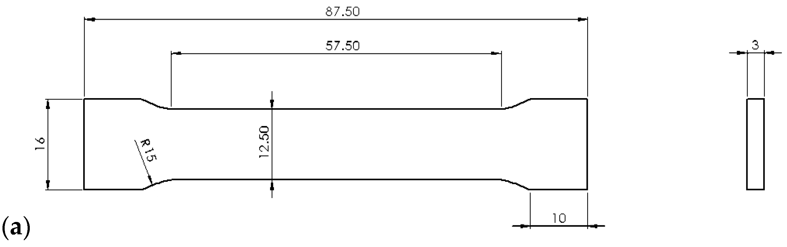
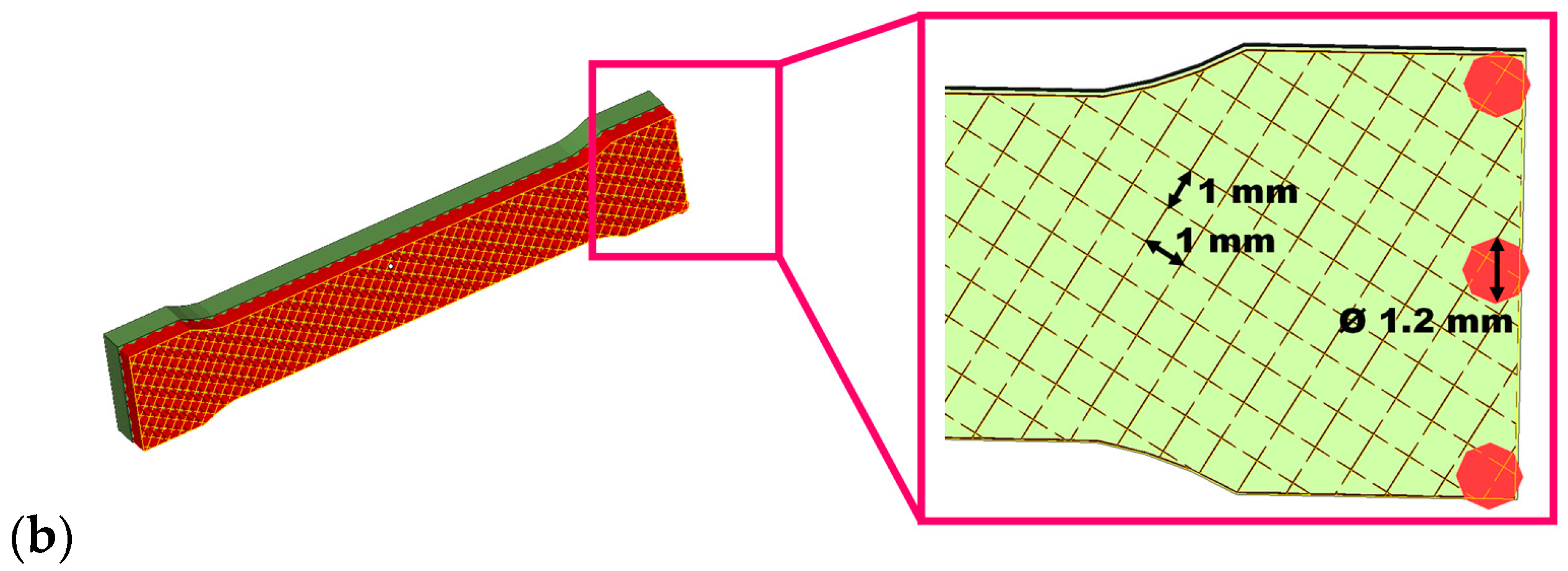
2.3. Physical–Mechanical Measurements

The experimental research conducted using the methodology described above allowed us to obtain 16 sets of specimens, which were evaluated for their tensile strength, hardness, and roughness characteristics. For each material and SLM process parameter (laser power) as described in Table 4, a minimum number of five specimens were tested. The values presented in the following tables are the mean values. The standard deviation was under 10% from the mean value, with a higher scattering for the specimens manufactured with a low laser power.
The ultimate tensile strength (Rm), Young’s modulus (E), and Poisson’s ratio were measured using the Instron 3366 (10 kN) and Instron 8801 (100 kN) testing machines, along with a unidirectional extensometer (Instron 2620-602; Instron Corporation, Norwood, MA 02062, USA) and a bidirectional extensometer (3560-Epsilon Tech; Epsilon Technology Corp., Jackson, WY 83001, USA). The testing parameters for the Instron equipment were set to a pulling speed of 2 mm/min and 50% humidity at ambient temperature.
The specimens were designed in accordance with ISO 6892:2019 [43] and were anchored using block supports with square lines of 1–2 mm in dimension. The cross-section of the parts was rectangular (see Figure 1). In some cases, it was challenging to grip the specimens with the extensometer, so a strain gauge technique was used to achieve the most accurate results for determining the elastic constants, particularly the Poisson’s ratio. A bidirectional strain gauge (C2A-06-062LT-120), supplied by VISHAY Micro-Measurements (Wendell, NC 27591, SUA), was used to measure the transverse contraction strain and longitudinal extension strain. These transducers are suitable for a wide range of deformation analyses and were directly connected to the recording device, an Amplifier Spider8.
Using a Mitutoyo SJ-2010 contact profilometer, the surface roughness of PBF samples was assessed on the top side. Roughness parameters Ra and Rz were calculated in accordance with ISO 4287 [44]. The arithmetical mean of the absolute values of the parameter deviations from the mean profile line is represented by the Ra roughness. The arithmetic mean value of the surface profile’s average highest and lowest peaks is denoted by Rz.
The hardness of the specimens was measured using the Vickers method with the Wilson Tukon 1102 equipment. Surface preparation involved wet grinding with silicon carbide disks and abrasive paper up to 600 grit. Micro-indentation hardness tests were conducted by applying a force of 9.81 N across the surface with a dwell time of 5 s, following the ASTM E384-17 standard [45]. A total of 15 successive trials were performed on the parts of the specimens that had previously been used for tensile tests.

2.4. Evaluation of the PBF Part Quality

The reliability of the PBF process for producing high-quality parts from specific materials, along with the criteria end users should consider evaluating whether PBF parts meet the required specifications, is thoroughly addressed in this paragraph. It aims to provide comprehensive answers and practical guidelines for effective PBF applications.
From a theoretical and scientific perspective, various researchers have successfully improved individual features of PBF specimens. However, from a practical standpoint, the main objective is to achieve an acceptable overall quality for industrial parts. In this experimental research, the PBF processing of each specific material was closely examined. Achieving this practical objective was made possible by thoroughly monitoring the manufacturing process and compiling detailed scientific reports for each set of PBF parameters. These comprehensive reports addressed all technological defects, as well as the interventions and distortions that occurred after removing the specimens from the platform.
To evaluate the manufacturing outcomes, a four-level ranking scale was developed for each bio-metal analyzed, as detailed below:
  • Rank 1—High risk of failure: Characterizes the inability to complete the manufacturing process due to high levels of residual stresses that damage either the part or its supports. In such cases, the PBF process must be halted at 40–50% completion (see Figure 2b,c).
  • Rank 2—Moderate risk of failure: Describes an unstable manufacturing process (see Figure 2a—left and middle sections) that may require temporary interruptions to remove some parts from the platform or cancel their production if multiple parts are involved. This rank may include successfully completed parts.
  • Rank 3—Moderate chance of success: Represents a stable process that requires continuous monitoring until the last layer is deposited. The manufacturing could be impacted by minor separations at the corners of the parts or micro-explosions that displace the powder (see Figure 2a—right side). In this case, despite manufacturing issues, such as the breaking of some supports due to internal stresses, the process can continue until completion. These phenomena can negatively affect the macro- and micro-structure of the parts, potentially leading to cracks or geometric deviations.
  • Rank 4—High chance of success: Reflects a successful and stable PBF process that does not require continuous observation. The macro- and micro-structures of the produced PBF parts meet the specified requirements.

3. Results

Table 5, Table 6, Table 7 and Table 8 present the levels of the manufacturability scale along with the average values of the corresponding physical–mechanical characteristics. Poisson’s ratio, hardness, and surface roughness were measured for the successfully manufactured samples, where the SLM process was completed without issues. In cases where failures occurred during the experiments, these measurements were not performed.

3.1. Manufacturing the SLM Specimens from Pure Ti Powder

Laser power in the range of 100–160 W was used to manufacture specimens from pure Ti powder. As shown in Table 5, when the laser power exceeds 120 W, manufacturability decreases, and the ultimate tensile strength (Rm) is lower. Structures produced using a laser power of 120 W are recommended because they exhibit lower residual stresses compared to those manufactured at 100 W. Generally, higher laser power leads to increased residual stresses.
For pure titanium, a laser power of 100 W was insufficient to provide the energy density needed to create an adequate melt pool. Only at 120 W was the PBF process optimal for producing reliable metal parts. Consequently, the authors chose to measure the Poisson’s ratio only for the specimens manufactured at 120 W.
During these experimental tests, a lower laser power (100 W) resulted in higher surface roughness compared to parts produced with 120 W. This finding was also confirmed by the Rz roughness parameter measurements presented in Table 5.
Table 5. Processability index and physical–mechanical characteristics of the pure Ti specimens.
Characteristics100 W120 W140 W160 W
Processability rank3433
Ultimate tensile stress, Rm [MPa]461441430401
Young’s modulus, E [GPa]751037980
Poisson’s ratio, ν-0.30--
Maximum elongation, A5 [%]8.46.544.5
Vickers hardness [HV1]234.2260.4--
Roughness Ra [µm]8.48.2--
Roughness Rz [µm]50.542.1--

3.2. Manufacturing the SLM Specimens from Ti6Al7Nb Powder

The laser power used for manufacturing the specimens ranged from 50 to 160 W. As shown in Table 6, the highest manufacturability rank (4) was achieved at low laser power values (50–70 W). However, the mechanical characteristics corresponding to 50 W were not acceptable. A laser power of 70 W is recommended to achieve both superior manufacturability and acceptable mechanical properties.
Additionally, a laser power of 100 W is recommended to obtain significantly improved mechanical properties (almost three times higher) compared to lower power settings, even though the PBF process has a slightly reduced success rate (rank 3). The Poisson’s ratio was determined for all laser power values used in these tests.
The highest roughness values were measured at the lower laser power settings (50–70 W). This can be attributed to the reduced energy input, which affects the surface quality of the manufactured parts.
Table 6. Processability index and physical–mechanical characteristics for Ti6Al7Nb specimens.
Characteristics50 W70 W100 W160 W
Processability rank4432
Ultimate tensile stress, Rm [MPa]20137400497
Young’s modulus, E [GPa]11388791
Poisson’s ratio, ν0.140.260.360.38
Maximum elongation, A5 [%]0.40.50.60.6
Vickers hardness [HV0.5]449.3427.5--
Roughness, Ra [µm]50.938.6--
Roughness, Rz [µm]246.4235.7--

3.3. Manufacturing of the SLM Specimens Made from CoCr Powder

Table 7 presents the reliability ranks and the physical–mechanical characteristics of the specimens manufactured by PBF using the following laser power values: 70 W, 85 W, 100 W, and 120 W. High reliability ranks were achieved at 85 W and 100 W. However, the PBF samples produced with 85 W showed higher deformations after being removed from the base plate.
Increasing the laser power resulted in better surface quality, confirming once again that a higher laser power enhances surface finish. Specifically, an increase in laser power up to 100 W reduced the Ra roughness to 16.9 µm (see Table 7).
Table 7. Processability index and physical–mechanical characteristics of the CoCr specimens.
Characteristics70 W85 W100 W120 W
Processability rank2442
Ultimate tensile stress, Rm [MPa]130503675862
Young’s modulus, E [GPa]109164198182
Poisson’s ratio, ν--0.22-
Maximum elongation, A5 [%]1.21.52.13.7
Vickers hardness [HV1]-512.2453.1-
Roughness Ra [µm]-20.716.9-
Roughness Rz [µm]-97.279.4-

3.4. Manufacturing of the SLM Specimens Made from CoCrWMo Powder

Various laser power values were used to manufacture the CoCrWMo specimens, ranging from 70 to 100 W (see Table 8). The optimal configuration of the process parameters, leading to acceptable results, was achieved at 85 W.
Using the process parameters detailed in Table 4 and a laser power of 90 W, the best Ra roughness value was obtained, with the smallest measured value of 5.1 µm.
Table 8. Processability index and physical–mechanical characteristics of the CoCrWMo specimens.
Characteristics70 W85 W90 W100 W
Processability rank3431
Ultimate tensile stress Rm [MPa]140811591358-
Young’s modulus, E [GPa]108199201-
Poisson’s ratio, ν-0.24--
Maximum elongation, A5 [%]1.51.361.39-
Vickers hardness [HV1]-544.8560.4-
Roughness Ra [µm]-12.85.1-
Roughness Rz [µm]-68.727.2-

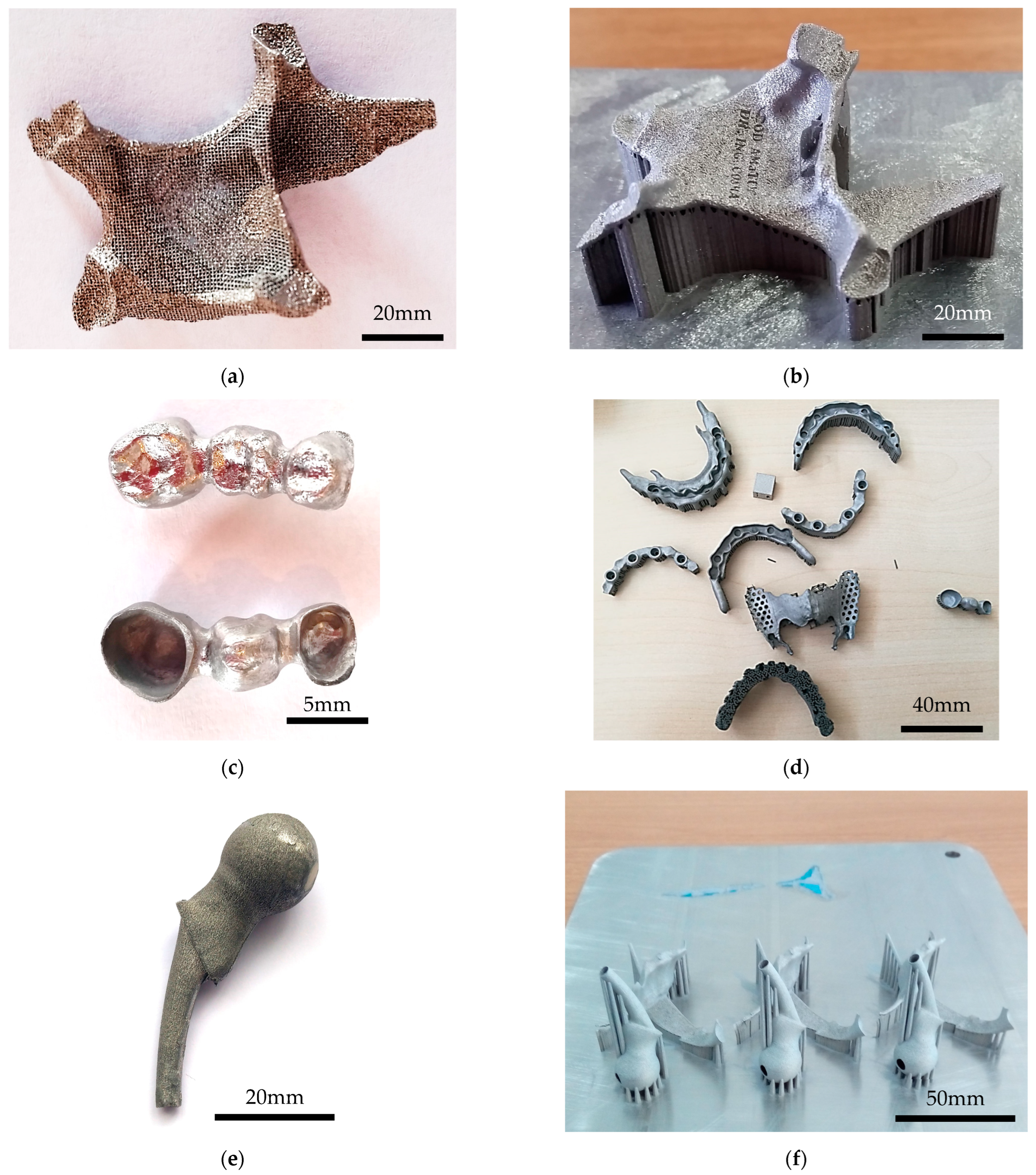
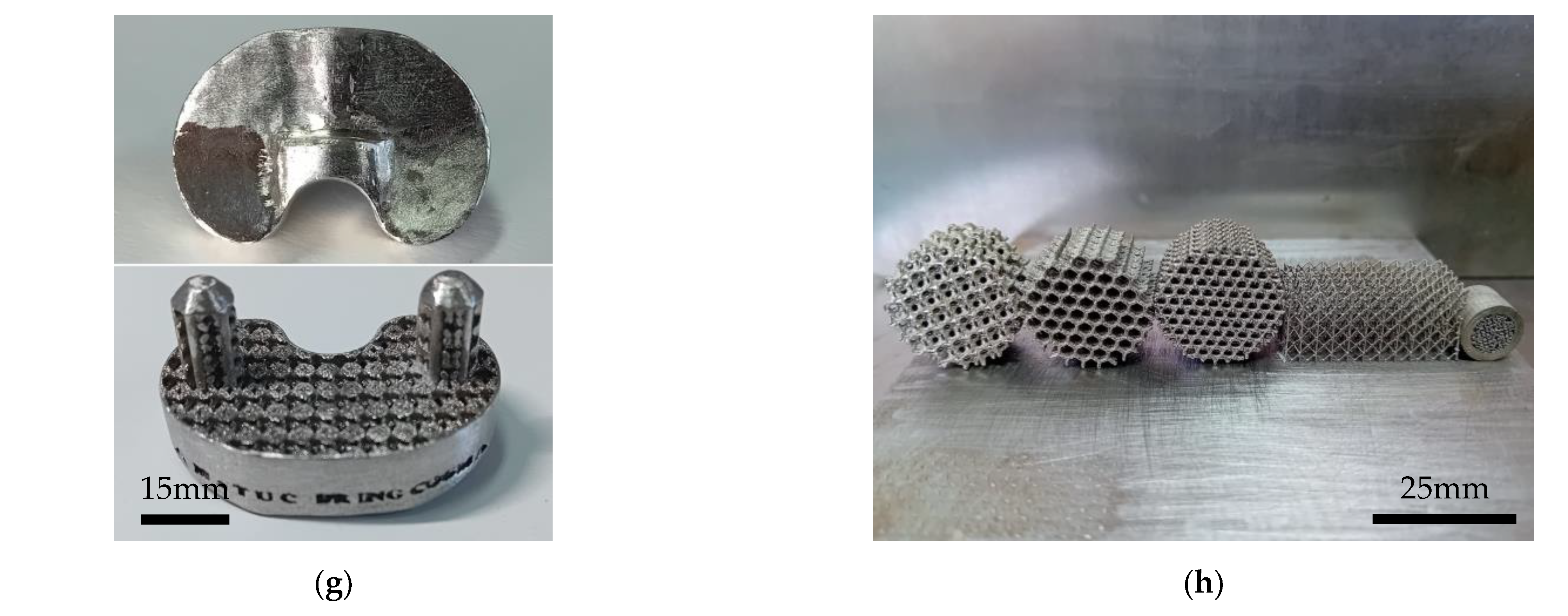
3.5. Real Parts Manufactured by PBF

Successful and stable PBF trials that do not require continuous observation were achieved. The microstructures and mechanical properties of the PBF parts meet the specified requirements. All the parts were designed and analyzed using the physical–mechanical characteristics determined in this work. For example, the maxillofacial implants illustrated in Figure 3a,b were fabricated from pure Ti powder (type TILOP 45) using the following PBF parameters: 120 W of laser power, 500 mm/s of scanning speed, and 0.12 mm of hatch distance (processability rank 4). In this case, the zygomatic reconstructions have 441 MPa of mechanical resistance, 103 GPa of elasticity modulus, 0.3 Poisson ratio, and 260 HV of surface hardness.
Figure 3c,d show different dental prosthetics such as bridges, complete protheses, and partial dentures (frames) made of CoCrWMo alloys. After printing, the dental bridge from Figure 3c was post-processed on external surfaces by alumina sandblasting at 2–3 bars for 10 min, and, then, it was manually polished with carborundum disks.
There are standardized implants for all the human bone systems, but the ideal is to have a customized one to patient needs, both from a design perspective and a physical–mechanical response. Recent advancements in the PBF process allow for the development of multi-material implant structures. Figure 3e,f reveal some hip orthopedic implants developed according to patent RO 132908B1/2024 with title “Process of Manufacturing Customized Multi-Structure Medical Implants by Additive Manufacturing Technologies” [46]. Knowing that we were using 70 W laser power and 400 mm/s scanning speed, with the elastic modulus of PBF implants made of Ti6Al7Nb similar to cortical bone (38 GPa), we were able to develop novel multi-material implants. In this case, to mimic the mechanical behavior of the cortical bone, the outer boundary of the hip implant was made of Ti6Al7Nb using the PBF parameters detailed above (2–3 mm thickness), and the final implant was infiltrated using an organic biocomposite (BISGMA and TEGDMA).
A knee replacement implant (tibial component) was possible to fabricate having a lattice structure inside of it (Figure 3g). The purpose of these scaffolds was to support bone ingrowth. After it was post-processed, the average dimensional deviation was +0.07 mm. Many designs of macro-porous grafts for regenerative medicine were successfully fabricated from CoCr alloy using the following PBF parameters: 100 W of laser power, 500 mm/s of scanning speed, and 0.10 mm of hatch distance (processability rank 4).

4. Discussions

Scanning speeds in the range of 350–500 mm/s were used in this research because such values reduce the risk of micro-void formation [22,47]. Results previously published by other researchers show that a 20–40 μm thickness of the powder layer leads to improved mechanical characteristics but diminishes productivity [7,9,22,48].
Considering the manufacturing time and powder grain size, this paper presents the process parameters suitable for a 50 μm layer thickness for pure Ti, Ti6Al7Nb, CoCr, and CoCrWMo powders. Table 5, Table 6, Table 7 and Table 8 present the SLM process parameters suitable for each alloy, leading to SLM parts with lower residual stress levels.
Typical manufacturing defects were identified as flowing: balling effect, micro-cracks, heat-affected zone, residual stress phenomena, etc. It is known that high laser power combined with a relatively low scanning speed may cause the material track to be completely melted or even broken due to excessive shrinkage and high residual stresses, resulting in many visible cracks [8]. The PBF process generates large temperature gradients near the exposure area, where there is high-energy density input [42]. If unmanaged, these gradients can lead to failures during manufacturing or undesirable residual stress artifacts (including distortion) and increased crack formation risks [1].
The microstructure evolution, micro-cracks and related boundary effects were analyzed and discussed on the basis of scanning electron microscopy (SEM) and metallographic analyses within our previews works [39]. The cracks appeared because, under the action of a moving a high-energy laser, the melting and solidification processes were completed in a short period of time, which induced a high-temperature gradient and high stress. As a result, the cracks tended to form to release the thermal stress. The recorded micro-cracks were irregularly distributed in the structure, having different lengths up to 100 µm.
Residual stress is attributed to temperature gradients due to the rapid heating and cooling rates during PBF [49]. The process parameters configured in this research produced parts with low deformations and limited residual stress levels. Specific process parameters were determined for each material to ensure good processability. Cracks or major defects are unacceptable in PBF-manufactured parts.
The physical–mechanical characteristics were influenced by microscopic cracks and pores, attributed to liquid film interruption at grain boundaries in the solidification temperature range due to tensile stress [11]. Macroscopic cracks significantly impacted the processability rank and occurred due to the low ductility of the material and stress-induced crack propagation [11].
Tensile tests were preferred over compression tests due to their capability of capturing the influence of micro-voids on mechanical characteristics. The mechanical properties were determined using standard specimens and tensile loads applied along the directions scanned by the laser beam. Under these testing conditions, the orientation of micro-voids and the solidification direction did not significantly influence the experimental results [50].
The tensile test results showed that laser power influences the physical–mechanical characteristics. For the Ti6Al7Nb and CoCr alloys, the ultimate tensile strength increases with higher laser power. In contrast, for pure Ti and CoCrWMo alloys, the opposite effect was observed. The total elongation of the PBF-manufactured specimens was low. This characteristic can be improved by heat treatments (annealing, quenching, or aging), thermo-chemical treatments (nitriding or carburizing), or hot isostatic pressing, depending on the chemical composition of the powder and the final application of the parts [7,16,17,18,19].
Recent experimental research conducted with Ti Grade I powder demonstrated that using a laser power of 120 W, a scanning speed of 500 mm/s, and a hatching distance of 0.12 mm resulted in parts with an ultimate tensile strength of 441 MPa, which is higher than the values reported in other similar studies on the same material [51].
There is a direct correlation between Vickers hardness and the total energy delivered by the laser beam. The reduction in hardness may be primarily attributed to microstructure roughening. The Vickers hardness values measured on the SLM samples were higher compared to the hardness of cast parts made from CoCr alloys. For example, at the same cobalt content level (59%), SLM parts manufactured from CoCrWMo powder exhibited a hardness of 544 HV1, whereas conventional Colado CC parts had a hardness of 407 HV1 [52]. In the case of pure titanium, the SLM samples showed hardness values ranging from 234 to 260 HV1, which were closer to the hardness of similar parts obtained through traditional manufacturing methods (255–290 HV1) [53].
While our current implementation provides consistent results across repeated runs, future extensions of this work could explore probabilistic or uncertainty-based formulations of direct methods to further support safety-critical applications.
One major challenge associated with Selective Laser Melting is the surface quality of the manufactured parts. Without any post-processing, the Ra roughness measured on the parts ranged between 5 and 50 µm, while the Rz roughness varied from 27 to 255 µm, depending on the material used and the configured process parameters. In almost all cases, a reduced laser power significantly increased the surface roughness due to the presence of semi-melted grains on the outer boundaries of the parts.
This phenomenon, along with other undesirable issues such as the balling effect, micro-pores, asymmetric streaks, and scratches, are prone to occur on surfaces during SLM manufacturing. To achieve a homogeneous surface and reduced roughness, the process parameters responsible for scanning the outer boundary of the parts should be optimized for each powder material type.
The ANOVA method offers a valuable approach to optimize process parameters by developing an empirical mathematical model through statistical techniques, mathematical combinations, and response surface methodology [54]. Additionally, post-processing techniques such as sandblasting with alumina, polishing with carborundum, and ultrasonication are commonly used to enhance the surface quality of PBF parts.
It is the authors’ aim to support reproducibility of our research. Despite the data limitation, we provided detailed descriptions of all relevant input parameters, including images of the processed samples and threshold values. This ensures replicability of the methodology using similar types of input data.

5. Conclusions

This article presents a guideline, useful mainly for new PBF machine users, on how to evaluate the practical characteristics of the PBF parts. The aim is to decrease the manufacturing time and to use a ranking system, to make sure that the mechanical properties are good for personalized medical implants made by PBF, using four types of biocompatible metal powders.
It is important to note that the mechanical characteristics presented in the tables are not necessarily the maximum achievable values. The primary goal was to produce reliable parts with overall mechanical properties above average. Crucially, these high-quality PBF parts do not require post-processing, an important advantage given that the high temperatures involved in some post-processing methods can induce phase transformations in biocompatible metals. This approach also contributes to time efficiency.
The values presented represent the average of the obtained results and can be used as such in finite element analyses, as they have been tested by the authors in numerous medical applications. With appropriate process parameters, increased hardness can be expected in the PBF parts. The Ra roughness values obtained ranged from 5 to 50 µm, with surface roughness quality dependent on both the material and the specific process parameter configuration.
Another key objective of this research was to minimize manufacturing time. Typically, such samples are built vertically or at an angle to reduce residual stress and the risk of damage, although this approach increases production time. In all experiments, specimens were built horizontally (so that Z is minimized), accepting the increased risk in order to minimize manufacturing time.
This ranking method shows potential for further development with other powder materials and different PBF machines.
The recommended process parameters for achieving good manufacturability are as follows:
  • Pure Titanium: 120 W, 500 mm/s, 0.12 mm;
  • Ti6Al7Nb: 70 W, 400 mm/s, 0.12 mm;
  • CoCr: 100 W, 500 mm/s, 0.10 mm;
  • CoCrWMo: 85 W, 500 mm/s, 0.10 mm.

Author Contributions

Conceptualization, D.V.L., C.C. and N.B.; methodology, D.V.L., C.C. and M.C.D.; investigation, D.V.L. and C.C.; validation, N.B. and M.C.D.; supervision, N.B. and M.C.D.; writing—original draft, D.V.L., C.C., N.B. and M.C.D.; writing—review and editing, D.V.L. and M.C.D.; research funding, D.V.L. All authors have read and agreed to the published version of the manuscript.

Funding

The APC was funded by Technical University of Cluj-Napoca, Romania.

Institutional Review Board Statement

Not applicable.

Informed Consent Statement

Not applicable.

Data Availability Statement

The original contributions presented in this study are included in the article. Further inquiries can be directed to the corresponding author.

Acknowledgments

This research was supported by the AM-CIR project (PN-II-RU-TE-2014-4-1157, no. 37/01.10.2015), financed by UEFISCDI under the authority of the Romanian Government.

Conflicts of Interest

The authors declare no conflicts of interest.

References

  1. Parry, L.; Ashcroft, I.; Wildman, R. Understanding the effect of laser scan strategy on residual stress in selective laser melting through thermo-mechanical simulation. Addit. Manuf. 2016, 12, 1–15. [Google Scholar] [CrossRef]
  2. Campbell, I.; Bourell, D.; Gibson, I. Additive manufacturing: Rapid prototyping comes of age. Rapid Prototyp. J. 2012, 18, 255–258. [Google Scholar] [CrossRef]
  3. Gibson, I.; Rosen, D.W.; Stucker, B. Additive Manufacturing Technologies; Springer: Boston, MA, USA, 2010. [Google Scholar]
  4. Qian, B.; Saeidi, K.; Kvetková, L.; Lofaj, F.; Xiao, C.; Shen, Z. Defects-tolerant Co-Cr-Mo dental alloys prepared by selective laser melting. Dent. Mater. 2015, 31, 1435–1444. [Google Scholar] [CrossRef] [PubMed]
  5. Jabbari, A. Physico-mechanical properties and prosthodontic applications of Co-Cr dental alloys: A review of the literature. J. Adv. Prosthodont. 2014, 6, 138. [Google Scholar] [CrossRef]
  6. Murr, L.E. Frontiers of 3D Printing/Additive Manufacturing: From Human Organs to Aircraft Fabrication. J. Mater. Sci. Technol. 2016, 32, 987–995. [Google Scholar] [CrossRef]
  7. Carter, L.N.; Martin, C.; Withers, P.J.; Attallah, M.M. The influence of the laser scan strategy on grain structure and cracking behaviour in SLM powder-bed fabricated nickel superalloy. J. Alloys Compd. 2014, 615, 338–347. [Google Scholar] [CrossRef]
  8. Song, B.; Dong, S.; Zhang, B.; Liao, H.; Coddet, C. Effects of processing parameters on microstructure and mechanical property of selective laser melted Ti6Al4V. Mater. Des. 2012, 35, 120–125. [Google Scholar] [CrossRef]
  9. Lu, Y.; Wu, S.; Gan, Y.; Li, J.; Zhao, C.; Zhuo, D.; Lin, J. Investigation on the microstructure, mechanical property and corrosion behavior of the selective laser melted CoCrW alloy for dental application. Mater. Sci. Eng. C 2015, 49, 517–525. [Google Scholar] [CrossRef]
  10. Cheng, B.; Shrestha, S.; Chou, K. Stress and deformation evaluations of scanning strategy effect in selective laser melting. Addit. Manuf. 2016, 12, 240–251. [Google Scholar] [CrossRef]
  11. Zhang, L.; Attar, H. Selective Laser Melting of Titanium Alloys and Titanium Matrix Composites for Biomedical Applications: A Review. Adv. Eng. Mater. 2016, 18, 463–475. [Google Scholar] [CrossRef]
  12. Mohammadkamal, H.; Caiazzo, F. Influence of absorptivity variation on Laser Powder Bed Fusion simulation and impact of process parameters on residual stress formation. Procedia CIRP 2024, 124, 335–340. [Google Scholar] [CrossRef]
  13. Mohammadkamal, H.; Caiazzo, F. Numerical Study to Analyze the Influence of Process Parameters on Temperature and Stress Field in Powder Bed Fusion of Ti-6Al-4V. Materials 2025, 18, 368. [Google Scholar] [CrossRef] [PubMed]
  14. Suzuki, A.; Shiba, Y.; Ibe, H.; Takata, N.; Kobashi, M. Machine-learning assisted optimization of process parameters for controlling the microstructure in a laser powder bed fused WC/Co cemented carbide. Addit. Manuf. 2022, 59, 103089. [Google Scholar] [CrossRef]
  15. Cao, Y.; Chen, C.; Xu, S.; Zhao, R.; Guo, K.; Hu, T.; Liao, H.; Wang, J.; Ren, Z. Machine learning assisted prediction and optimization of mechanical properties for laser powder bed fusion of Ti6Al4V alloy. Addit. Manuf. 2024, 91, 104341. [Google Scholar] [CrossRef]
  16. Mantrala, K.M.; Das, M.; Balla, V.K.; Rao, C.S.; Rao, V.V.S.K. Additive manufacturing of Co-Cr-Mo alloy: Influence of heat treatment on microstructure, tribological, and electrochemical properties. Front. Mech. Eng. 2015, 1, 2. [Google Scholar] [CrossRef]
  17. Kruth, J.-P.; Levy, G.; Klocke, F.; Childs, T. Consolidation phenomena in laser and powder-bed based layered manufacturing. CIRP Ann. 2007, 56, 730–759. [Google Scholar] [CrossRef]
  18. Wu, M.-W.; Lai, P.-H. The positive effect of hot isostatic pressing on improving the anisotropies of bending and impact properties in selective laser melted Ti-6Al-4V alloy. Mater. Sci. Eng. A 2016, 658, 429–438. [Google Scholar] [CrossRef]
  19. Vrancken, B.; Thij, L.; Kruth, J.P.; Humbeeck, J.V. Heat treatment of Ti6Al4V produced by Selective Laser Melting: Microstructure and Mechanical properties. J. Alloys Compd. 2012, 541, 177–185. [Google Scholar] [CrossRef]
  20. Engelia, R.; Ettera, T.; Hövela, S.; Wegenerba, K. Processability of different IN738LC powder batches by selective laser melting. J. Mater. Process. Technol. 2016, 229, 484–491. [Google Scholar] [CrossRef]
  21. Su, X.; Yang, Y.; Xiao, D.; Chen, Y. Processability investigatation of non-assembly mechanisms for powder bed fusion process. Int. J. Adv. Manuf. Technol. 2013, 64, 1193–1200. [Google Scholar] [CrossRef]
  22. Song, C.; Yang, Y.; Wang, Y.; Wang, D.; Yu, J. Research on rapid manufacturing of CoCrMo alloy femoral component based on selective laser melting. Int. J. Adv. Manuf. Technol. 2014, 75, 445–453. [Google Scholar] [CrossRef]
  23. Lupo, M.; Ajabshir, S.Z.; Sofia, D.; Barletta, D.; Poletto, M. Experimental metrics of the powder layer quality in the selective laser sintering process. Powder Technol. 2023, 419, 118346. [Google Scholar] [CrossRef]
  24. Salehi, H.; Cummins, J.; Gallino, E.; Harrison, N.; Hassanpour, A.; Bradley, M. A new approach to quantify powder’s bed surface roughness in additive manufacturing. Powder Technol. 2022, 407, 117614. [Google Scholar] [CrossRef]
  25. Mehrabi, M.; Gardy, J.; Talebi, F.A.; Farshchi, A.; Hassanpour, A.; Bayly, A.E. An investigation of the effect of powder flowability on the powder spreading in additive manufacturing. Powder Technol. 2023, 413, 117997. [Google Scholar] [CrossRef]
  26. ISO 13320:2020; Particle Size Analysis—Laser Diffraction Methods. ISO: Geneva, Switzerland, 2020.
  27. ASTM B213; Standard Test Method for Flow Rate of Metal Powders Using the Hall Flowmeter Funnel. ASTM International: West Conshohocken, Pennsylvania, USA, 2020.
  28. Shen, X.; Shukla, P.; Sharma, D.; Zammit, A.; Swanson, P.; Jiao, Y.; Lawrence, J. On restructuring the microstructure of Ti-6Al-7Nb alloy before surface engineering. Mater. Charact. 2020, 169, 110629. [Google Scholar] [CrossRef]
  29. Hedberg, Y.S.; Qianc, B.; Shenc, Z.; Virtanena, S.; Wallinder, I.O. In vitro biocompatibility of CoCrMo dental alloys fabricated by selective laser melting. Dent. Mater. 2014, 30, 525–534. [Google Scholar] [CrossRef]
  30. Wataha, J.C.; Schmalz, G. Dental alloys. In Biocompatibility of Dental Materials; Springer: Berlin/Heidelberg, Germany, 2009; pp. 221–254. [Google Scholar]
  31. Van, N.R. The future of dental devices is digital. Dent. Mater. 2012, 28, 3–12. [Google Scholar]
  32. ASTM F75; Standard Specification for Cobalt-28 Chromium-6 Molybdenum Alloy Castings for Surgical Implants, UNS R30075. ASTM International: West Conshohocken, Pennsylvania, USA, 2021.
  33. ISO 22674:2016; Dentistry—Metal Materials for Fixed and Removable Restorations and Appliances. ISO: Geneva, Switzerland, 2016.
  34. Rotaru, H.; Armencea, G.; Spîrchez, D.; Berce, C.; Marcu, T.; Leordean, D.; Kim, S.-G.; Bǎciuţ, M. In vivo behavior of surface modified Ti6Al7Nb alloys used in selective laser melting for custom-made implants. A preliminary study. Rom. J. Morphol. Embryol. 2013, 54, 791–796. [Google Scholar]
  35. Marcu, T.; Menapace, C.; Girardini, L.; Leordean, D.; Popa, C. Selective laser melting of Ti6Al7Nb with hydroxyapatite addition. Rapid Prototyp. J. 2014, 20, 301–310. [Google Scholar] [CrossRef]
  36. Leordean, D.; Radu, S.A.; Frățilă, D.; Berce, P. Studies on design of customized orthopedic endoprostheses of titanium alloy manufactured by SLM. Int. J. Adv. Manuf. Technol. 2015, 79, 905–920. [Google Scholar] [CrossRef]
  37. Marcu, T.; Todea, M.; Maines, L.; Leordean, D.; Berce, P.; Popa, C. Metallurgical and mechanical characterisation of titanium based materials for endosseous applications obtained by selective laser melting. Powder Met. 2012, 55, 309–314. [Google Scholar] [CrossRef]
  38. Leordean, D.; Dudescu, C.; Marcu, T.; Berce, P.; Bâlc, N. Customized implants with specific properties, made by selective laser melting. Rapid Prototyp. J. 2015, 21, 98–104. [Google Scholar] [CrossRef]
  39. Cosma, C.; Drstvensek, I.; Berce, P.; Prunean, S.; Legutko, S.; Popa, C.; Balc, N. Physical–mechanical characteristics and microstructure of Ti6Al7Nb lattice structures manufactured by selective laser melting. Materials 2020, 13, 4123. [Google Scholar] [CrossRef] [PubMed]
  40. Mierzejewska, Ż.A.; Hudák, R.; Sidun, J. Mechanical Properties and Microstructure of DMLS Ti6Al4V Alloy Dedicated to Biomedical Applications. Materials 2019, 12, 176. [Google Scholar] [CrossRef]
  41. Miranda, G.; Faria, S.; Bartolomeu, F.; Pinto, E.; Madeira, S.; Mateus, A.; Carreira, P.; Alves, N.; Silva, F.S.; Carvalho, O. Predictive models for physical and mechanical properties of 316L stainless steel produced by selective laser melting. Mater. Sci. Eng. A 2016, 657, 43–56. [Google Scholar] [CrossRef]
  42. Yadroitsev, I.; Krakhmalev, P.; Yadroitsava, I.; Johansson, S.; Smurov, I. Energy input effect on morphology and microstructure of selective laser melting single track from metallic powder. J. Mech. Work. Technol. 2013, 213, 606–613. [Google Scholar] [CrossRef]
  43. ISO 6892:2019; Metallic Materials—Tensile Testing—Part 1: Method of Test at Room Temperature. ISO: Geneva, Switzerland, 2019.
  44. ISO 4287:1997; Geometrical Product Specifications (GPS)—Surface texture: Profile method. ISO: Geneva, Switzerland, 2009.
  45. ASTM E384-17; Standard Test Method for Knoop and Vickers Hardness of Materials. ASTM International: West Conshohocken, PA, USA, 2017.
  46. Leordean, V.D.; Radu, A.; Cosma, C.; Cuc, S.; Vilău, C.; Rusu, M. Process of Manufacturing Customized Multi-Structure Medical Implants by Additive Manufacturing Technologies. Patent RO132908B1, 28 February 2024. [Google Scholar]
  47. Meier, H.; Haberland, C. Experimental studies on selective laser melting of metallic parts. Mater. Und Werkst. 2008, 39, 665–670. [Google Scholar] [CrossRef]
  48. Simonelli, M.; Tuck, C.; Aboulkhair, N.T.; Maskery, I.; Ashcroft, I.; Wildman, R.D.; Hague, R. A Study on the Laser Spatter and the Oxidation Reactions During Selective Laser Melting of 316L Stainless Steel, Al-Si10-Mg, and Ti-6Al-4V. Met. Mater. Trans. A 2015, 46, 3842–3851. [Google Scholar] [CrossRef]
  49. Attar, H.; Calin, M.; Zhang, L.C.; Scudino, S.; Eckert, J. Manufacture by selective laser melting and mechanical behavior of commercially pure titanium. Mater. Sci. Eng. A 2014, 593, 170–177. [Google Scholar] [CrossRef]
  50. Chlebus, E.; Kuźnicka, B.; Kurzynowski, T.; Dybala, B. Microstructure and mechanical behaviour of Ti―6Al―7Nb alloy pro-duced by selective laser melting. Mater. Charact. 2011, 62, 488–495. [Google Scholar] [CrossRef]
  51. Laoui, T.; Santos, E.; Osakada, K.; Shiomi, M.; Morita, M.; Shaik, S.K.; Tolochko, N.K.; Abe, F.; Takahashi, M. Properties of titanium dental implant models made by laser processing. Proc. Inst. Mech. Eng. Part C J. Mech. Eng. Sci. 2006, 220, 857–863. [Google Scholar] [CrossRef]
  52. Dobrzański, L.A.; Reimann, L. Influence of Cr and Co on hardness and corrosion resistance CoCrMo alloys used on dentures. J. Achiev. Mater. Manuf. Eng. 2011, 49, 193–199. [Google Scholar]
  53. Torun, G. Microstructure and mechanical properties of CP-titanium (grade 4) implant materials. Matter 2015, 2, 33–39. [Google Scholar]
  54. Franczyk, E.; Machno, M.; Zębala, W. Investigation and Optimization of the SLM and WEDM Processes’ Parameters for the AlSi10Mg-Sintered Part. Materials 2021, 14, 410. [Google Scholar] [CrossRef]
Figure 1. (a) Geometrical dimensions of standard samples, according to ISO 6892 [43]. (b) Support type: block (e.g., 1 × 1 mm) and conical (e.g., Ø 1.2 mm).
Applsci 15 04542 g001aApplsci 15 04542 g001b
Figure 2. Samples made from CoCr with manufacturing issues. (a) Supports detached from the parts and SLM platform. (b) Parts with cracks caused by residual stresses. (c) Supports with cracks caused by residual stresses.
Applsci 15 04542 g002
Figure 3. Real parts fabricated by SLM: (a,b) Maxillofacial implants—pure Ti, (c,d) dental applications—CoCrWMo, (e,f) orthopedic implants—Ti6Al7Nb, (g) orthopedic implants, and (h) lattice grafts—CoCr.
Applsci 15 04542 g003aApplsci 15 04542 g003b
Table 1. Chemical composition of the Ti6Al7Nb powder.
Chemical ElementAlNbTaFeOCNHTi
Maximum
weight percentage [%]
6.57.50.50.250.200.080.050.00984.9
Table 2. Chemical composition of the CoCr powder.
Chemical ElementCoCrMoMnSiNiFeC
Maximum
weight percentage [%]
58.9–69.527–305–7max. 1max. 1max. 1max. 0.75max. 0.75
Table 3. Chemical composition of the CoCrWMo powder.
Chemical ElementCoCrW MoSi Other Elements (C, Fe, Mn, N)
Maximum
weight percentage [%]
59259.53.51<1
Table 4. SLM process parameters to produce testing samples.
MaterialLaser Power
[W]
Scanning Speed
[mm/s]
Layer Thickness
[µm]
Hatch Distance
[mm]
Ti100500500.12
120
140
160
Ti6Al7Nb50400500.12
70
100
160
CoCr70500500.10
85
90
100
CoCrWMo70500500.10
85
90
100
Disclaimer/Publisher’s Note: The statements, opinions and data contained in all publications are solely those of the individual author(s) and contributor(s) and not of MDPI and/or the editor(s). MDPI and/or the editor(s) disclaim responsibility for any injury to people or property resulting from any ideas, methods, instructions or products referred to in the content.

