Article

Diffusion and Consolidation of Slag-Based Geopolymer for Concrete Pavement Rehabilitation

1
School of Civil Engineering and Architecture, Henan University of Science and Technology, Luoyang 471000, China
2
Yellow River Laboratory, Zhengzhou University, Zhengzhou 450001, China
*
Author to whom correspondence should be addressed.
Appl. Sci. 2025, 15(8), 4373; https://doi.org/10.3390/app15084373
Submission received: 6 March 2025 / Revised: 8 April 2025 / Accepted: 14 April 2025 / Published: 15 April 2025

Abstract

:
Homogenized micro-crack crushing is an optimal rehabilitation technology for concrete pavement; however, when there are weak road base issues, some measures need to be taken to treat the diseases. Grouting is a common technique for addressing weak road base issues. This study developed a new visual indoor grouting test system to analyze the diffusion and consolidation of slag-based geopolymer slurry. The reactants of the geopolymer and the consolidation state of the slurry and aggregate were observed. Moreover, the reinforcement effect of the slurry on a weak road base was studied through the on-site grouting and excavation of the test pit. The results show that, during indoor grouting tests, as the size of the aggregate decreases, the slurry diffusion depth gradually decreases: only 9.5–4.75 mm aggregate formed a complete cylindrical specimen. In the tests of unformed cylindrical specimens, the 9.5–4.75 mm aggregate will develop 20–50 mm splitting surfaces, while the 4.75–2.36 mm aggregate will develop slurry bulbs and veins of different sizes, but the development is not obvious in the 2.36–1.18 mm aggregate. Fine aggregate grouting will exhibit the pressure filtration effect—especially for the 2.36–1.18 mm aggregate, the pressure filtration effect is the most obvious. An SEM microstructural analysis demonstrated that the geopolymer with a water–slag ratio of 0.4 has a faster hydration and dissolution, which results in a decrease in the density of local reactants. However, the polymerization of geopolymers is more complete. The pores of the coarse aggregate are larger and the slurry filling is denser, while the pores of the fine aggregate are smaller and the consolidation is loose locally. The consolidation of aggregates has cracks at local locations, but the width of the cracks is relatively small. On-site grouting applications revealed that the geopolymer slurry filled the bottom voids of pavement slabs and deep gaps in the road base layers, and the average deflection of the driveway decreased from 104.8 (0.001 mm) to 48 (0.001 mm) after grouting. Weak road base conditions were successfully treated, leading to a significant improvement in bearing capacity.

1. Introduction

Concrete pavement is a common road structure in China, known for its high strength, simple construction, good durability, and lower maintenance requirements, which has been developed rapidly. As the service life of concrete pavement gradually increases, various diseases will appear. As concrete pavement deteriorates over time, rehabilitation becomes necessary in order to maintain structural integrity, and the main rehabilitation method is to remove or crush the surface layer. The methods of crushing concrete pavements include impact compactors, guillotine breakers, multiple head breakers, resonant pavement breakers, and homogenized micro-crack crushing. Impact compactors and guillotine breakers may cause a substantial disturbance and damage to the road base during construction, potentially leading to a severe reduction in the bearing capacity of certain road sections. In contrast, multiple head breakers and resonant pavement breakers induce less disturbance to the road base. However, the concrete slab is crushed into smaller blocks, which significantly reduces its bearing capacity. Consequently, these methods require the subsequent placement of a cement-stabilized aggregate base layer and a relatively thick asphalt concrete overlay. Among various pavement breaking techniques, the homogenized micro-crack crushing technology combines the advantages of several previous crushing methods. Using this technology, concrete pavement is crushed, and different broken blocks are interlocked. The bearing capacity of the old concrete pavement is fully preserved, so that the asphalt mixture can be directly overlaid [1]. However, there are cavities beneath the slab and loose road base, which lead to an insufficient bearing capacity [2]. After the cement pavement is crushed, the road base bearing capacity needs to be improved by grouting. Geopolymers offer key advantages, including early strength development, rapid setting, and high stability, making them suitable for grouting applications.
Geopolymers can be prepared by using metakaolin, blast furnace slag, fly ash, and steel slag under the excitation of the alkali activator. Due to its excellent mechanical properties and the wide availability of raw materials, many scholars have prepared different geopolymer grouting materials. For soil reinforcement grouting, Huynh et al. [3] developed geopolymer grouts for filling the void structures of coarse reclaimed asphalt planing (RAP) skeletons. Using slag and fly ash, Xu et al. [4] prepared a high-performance geopolymer grouting material. Zhou et al. [5] developed a new road grouting material using volcanic ash and metakaolin. Xu et al. [6] conducted a study on different performance indicators of high-calcium basalt fiber geopolymer grouting material. Through experiments, Zhang et al. [7] prepared a new type of geopolymer grouting material with a different combination of powder materials, alkalis, and activators. Li et al. [8] investigated the workability and microstructure of a red mud-slag based geopolymer. Güllü and Agha [9] conducted research on metakaolin and slag cold-bonded geopolymer stabilizers. Li et al. [10] prepared a new underground engineering grouting material using slag-red mud. Tian et al. [11] prepared a latex-modified geopolymeric grout (LMGG) and compared the physical properties of the LMGG with cement-based grouts. Guo et al. [12] developed a low-cost geopolymer grouting material using different industrial waste materials. Through experiments, Li et al. studied [13] the rheological and viscoelastic properties of the geopolymer grouting material. For repairing the damaged reinforced concrete (RC) beam, Kantarci et al. [14] prepared a new geopolymer grout. Guo et al. [15] developed a cost geopolymer grouting repair material, studied its mechanical and microscopic properties. Duan et al. [16] developed eco-friendly geopolymer grouting materials using industrial wastes as the main raw materials. Yang et al. [17] developed road grouting materials using volcanic ash and metakaolin (MK). Wei et al. [18] prepared a new modified metakaolin-based geopolymer, and studied its various mechanical properties. Through indoor tests, Li et al. [19] studied the mechanical properties of the slag-based geopolymer. Li et al. [20] prepared a fly-ash-based geopolymer using different ratios of alkali activators and metakaolin. Zhang et al. [21] developed a green geopolymer using red mud and granulated blast furnace slag. Through indoor tests, Li et al. [22] prepared a new, cleaner double liquid alkali-activated grouting material (DLAG). Souayfan et al. [23] studied the effected of the H2O/Na2O ratio and two acids on the hardening rates of slag-based grouts. Güllü et al. [24] studied the influence of nano-silica-added geopolymer-based grout mixtures.
When using a geopolymer for reinforcement in concrete pavement, there are many influencing factors in the filling and diffusion of the geopolymer grouting material, so it is necessary to study the diffusion characteristics through on-site or indoor grouting tests. The indoor grouting test has a good repeatability and visualization, which can intuitively help us study the distribution of solidified slurry and analyze the diffusion law. Many scholars have developed various indoor grouting test systems and conducted a series of grouting tests. Wang et al. [25] developed a grouting experimental system for studying the slurry flow through rock fractures. Liu et al. [26] developed a visualized fracture grouting experimental system for simulating the flow process of the fracture network. Hao et al. [27] designed a visual fracture grouting system and discussed the influences of grouting quantity on the grout diffusion distance. Han et al. [28] developed a grouting test system for a series of laboratory tests. Zhu et al. [29] developed a single-fracture stress–seepage coupling test system and conducted grouting material seepage tests. Hu et al. [30] prepared a three-dimensional grouting experimental system and studied the diffusion mechanism of sand soil. Li et al. [31] developed a test system for grouting in rough fractured rock masses. Hu et al. [32] developed a visual experimental platform for grouting in a fractured aquifer.
In summary, many researchers focused on the development of various geopolymer grouting materials using slag, fly ash, and metakaolin. In terms of indoor grouting tests, many scholars developed indoor grouting test systems and conducted the corresponding grouting reinforcement research in soil layers, sand layers, rock fractures, etc. However, limited research has been conducted on the application of geopolymers in pavement rehabilitation, and the investigation of the related microstructure to mechanical consolidation, as well as the study of slurry diffusion with different aggregate gradations. This study aims to bridge that gap by investigating the diffusion and consolidation behavior of a slag-based geopolymer used for road base grouting after the homogenization of concrete pavement. A new visual indoor grouting experimental system was developed to study the diffusion and consolidation characteristics of geopolymer grouting material for single-graded aggregate. Moreover, the bonding characteristics between the geopolymer grouting slurry and aggregate were observed using SEM. Furthermore, the reinforcement effect of the slag-base geopolymer grouting slurry for the loose aggregate in the road base was studied on site after the homogenization of concrete pavement.

2. Experimental

2.1. Preparation of Geopolymer Grouting Material

For geopolymer grouting material, considering its easy availability and environmental friendliness, blast furnace slag was selected as the raw material for geopolymer. The density of the slag powder is 2.93 g/cm3 and the specific surface area is 459 m2/kg. As shown in Table 1, the main components of slag included silicon oxide, calcium oxide, aluminum oxide, magnesium oxide, etc. Among all components of slag powder, silicon oxide, calcium oxide, and aluminum oxide serve as the primary sources of gels for polymerization reactions.
The XRD patterns of blast furnace slag powder are shown in Figure 1. When the diffraction angle was at 30°, a diffuse diffraction peak region appeared, indicating that the main structure of the material was amorphous, with a large amount of glass phase components.
The geopolymer was prepared using slag powder and alkaline activator, and, considering that the content of alkali activator affects setting rate of slag-based geopolymers, it was essential to determine an optimal mix proportion. The alkali activator was prepared with sodium silicate and sodium hydroxide with a ratio of 10.1:1. Considering characteristics of early strength and fast setting of geopolymer, in order to study the diffusion and consolidation of geopolymer slurry, it was found that geopolymer grouting material with a water–slag powder ratio of 0.4 was suitable. Due to the lack of corresponding geopolymer testing codes, the grouting tests were conducted with reference to “Testing Methods of Cement and Concrete for Highway Engineering” (JTG 3420-2020) [33].

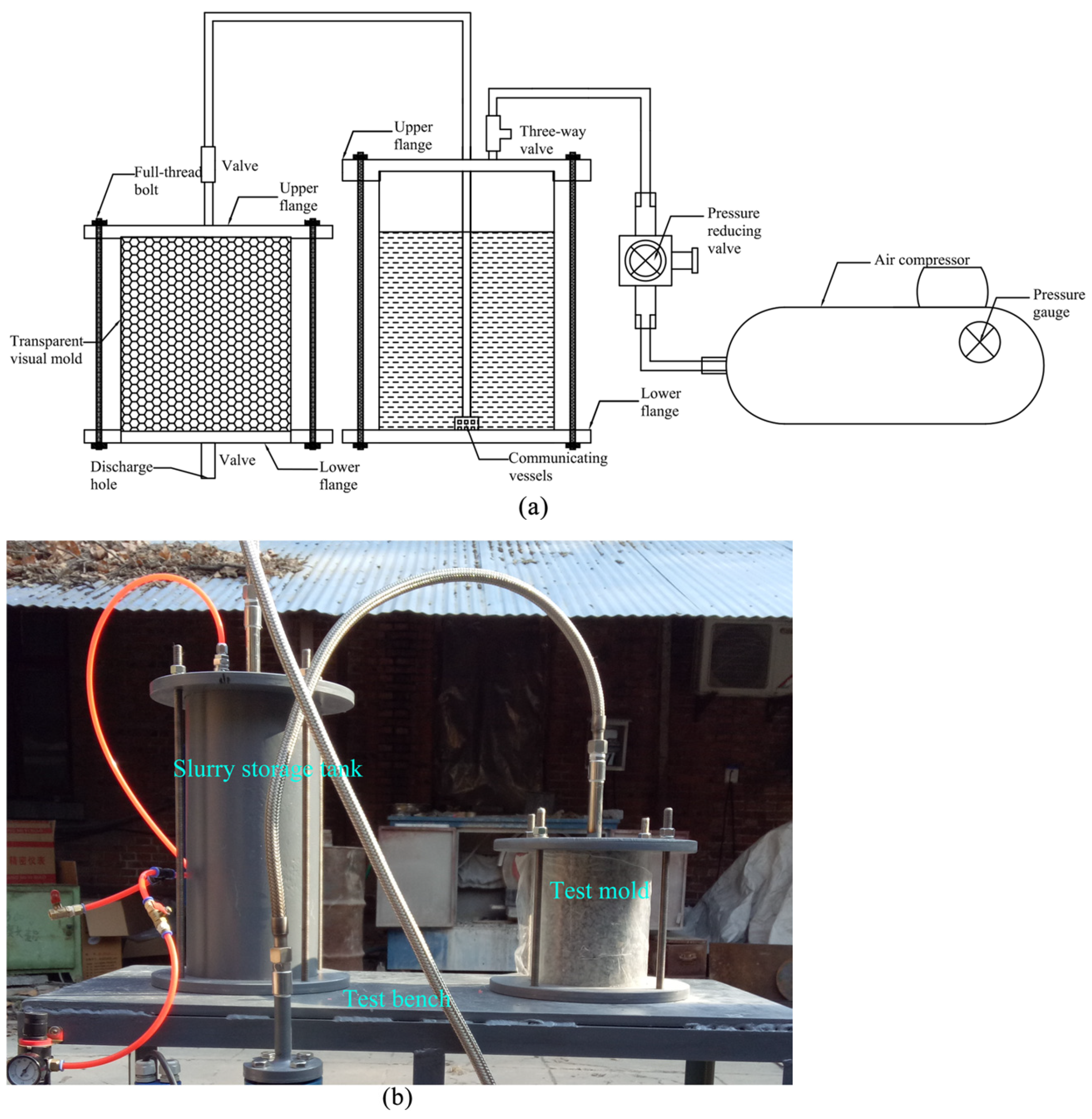
2.2. New Grouting System

In indoor grouting tests, the new-developed visual grouting test system mainly consists of an air compressor, slurry storage tank, pressure reducing valve, test mold, and test bench. The indoor grouting test system is shown in Figure 2, in which Figure 2a illustrates the testing schematic diagram, while Figure 2b displays the primary test platform after assembly. The air compressor mainly provides grouting pressure, and the pressure range is 0~1.25 MPa. The slurry storage tank is a container of geopolymer slurry in grouting tests, which is made of seamless steel pipe, and the slurry storage tank is sealed by rubber rings of the upper and lower flanges. The upper flange contains a slurry outlet and an air inlet. The pressure reducing valve is mainly used to adjust the grouting pressure, and the pressure adjustment range is 0.1 MPa~1 MPa. The test mold is made of acrylic cylinder, which also adopts the sealing method of upper and lower flanges with rubber rings. The upper flange plate contains a slurry inlet, and the lower flange plate contains a slurry outlet, both of which are equipped with valves. The transparent test cylinder mold has an inner diameter of 150 mm, a height of 200 mm, and a thickness of 10 mm. The test bench is a support platform for the slurry storage tank and the test mold. Due to the separated design method of the grouting test system, it is convenient for the disassembly and cleaning of the slurry storage tank and the test mold.

2.3. Testing Methods

2.3.1. Indoor Grouting Test

In the geopolymer grouting tests, three kinds of single-graded aggregate of 9.5–4.75 mm, 4.75–2.36 mm, and 2.36–1.18 mm were used to simulate disease of loose granular material of road base. The pore parameters of each aggregate are shown in Table 2, which are tested according to “Test Methods of Aggregates for Highway Engineering” (JTG 3432-2824) [34]. In the grouting test, porosity was a key parameter. Due to the different porosity of aggregate with different particle sizes, different grouting pressures were required. Preliminary test results indicate that the optimal grouting pressure ranges are as shown in Table 3. For each gradation of aggregates, three parallel tests were conducted under different grouting pressure conditions. Based on the test results, the optimal specimens were selected for experimental observation. The main process of indoor geopolymer grouting test is as follows:
(1)
Firstly, the slurry storage tank and test mold were assembled, and the aggregate was filled and compacted in layers to meet the requirements of controlling porosity.
(2)
The connection of pipelines between the air pump compressor, pressure reducing valve, and three-way valve were checked, so as to ensure that the slurry storage tank can be pressurized normally and the pressure reducing valve can adjust the pressure properly.
(3)
The geopolymer grouting slurry was prepared according to the designed water–slag ratio.
(4)
The slurry was poured into the storage tank, and the top flange was securely tightened to prevent leakage.
(5)
The air valve was opened for grouting test, and the geopolymer slurry gradually diffused in the test mold. In the test mold, when the slurry basically did not change for 1 min, the grouting valve on the top flange of the test mold was closed, and the air valve was also closed at the same time.

2.3.2. Microscopic Test of Geopolymer

The reactants and consolidation characteristics of slag-based geopolymer grouting material were observed by SEM, and the qualitative and quantitative analysis of the grouting test specimen of geopolymer were also conducted.

3. Results and Discussion

3.1. Single-Gradation 9.5–4.75 mm Grouting Test

When the particle size of the grouting aggregate was 9.5–4.75 mm, as the grouting pressure increased, higher grouting pressures led to better slurry consolidation, resulting in more uniform specimens, as shown in Figure 3. When the grouting pressure was 0.2 MPa, the geopolymer slurry diffused and solidified a certain height of aggregate, and then significant slurry bulbs and veins appeared; however, the height of the solidified aggregate did not reach the height of the grouting test mold. When the grouting pressure was 0.3 MPa, the geopolymer slurry almost diffused and solidified the entire aggregate of the test mold. However, the aggregate at the bottom of the test mold was not consolidated, and there were pits in some areas. When the grouting pressure was 0.4 MPa, the geopolymer slurry filled the inside of the test mold and consolidated the aggregate, but there were certain pores on the specimen surface.
As shown in Figure 4, under the condition of a 0.2 MPa grouting pressure and subtracting the simulated void area with a reserved thickness of 10 mm, the consolidation thickness of the geopolymer slurry in the 9.5–4.75 mm aggregate was 50 mm. A hemispherical slurry bulb was formed in the lower part of the consolidation zone, and there were many developed slurry veins. It could be seen that the first splitting surface was relatively thick, with a maximum thickness of about 50 mm. The second splitting surface developed diagonally along the first splitting surface, but was not fully developed, with a maximum thickness of about 20 mm.
Due to the slightly larger pore size of the aggregate with a particle size of 9.5–4.75 mm, the slurry diffused in a hemispherical shape to form slurry bulbs. When the pores in some positions of the aggregate were filled, the slurry began to seek diffusion along the weak surface, gradually forming a splitting surface. After the first splitting surface was generated, the surrounding aggregate was compressed, and a second splitting surface usually appeared along the direction of intersection of the first splitting surface. At the end of grouting, the specimen would appear in the form of bulbs at the top and slurry veins at the bottom.

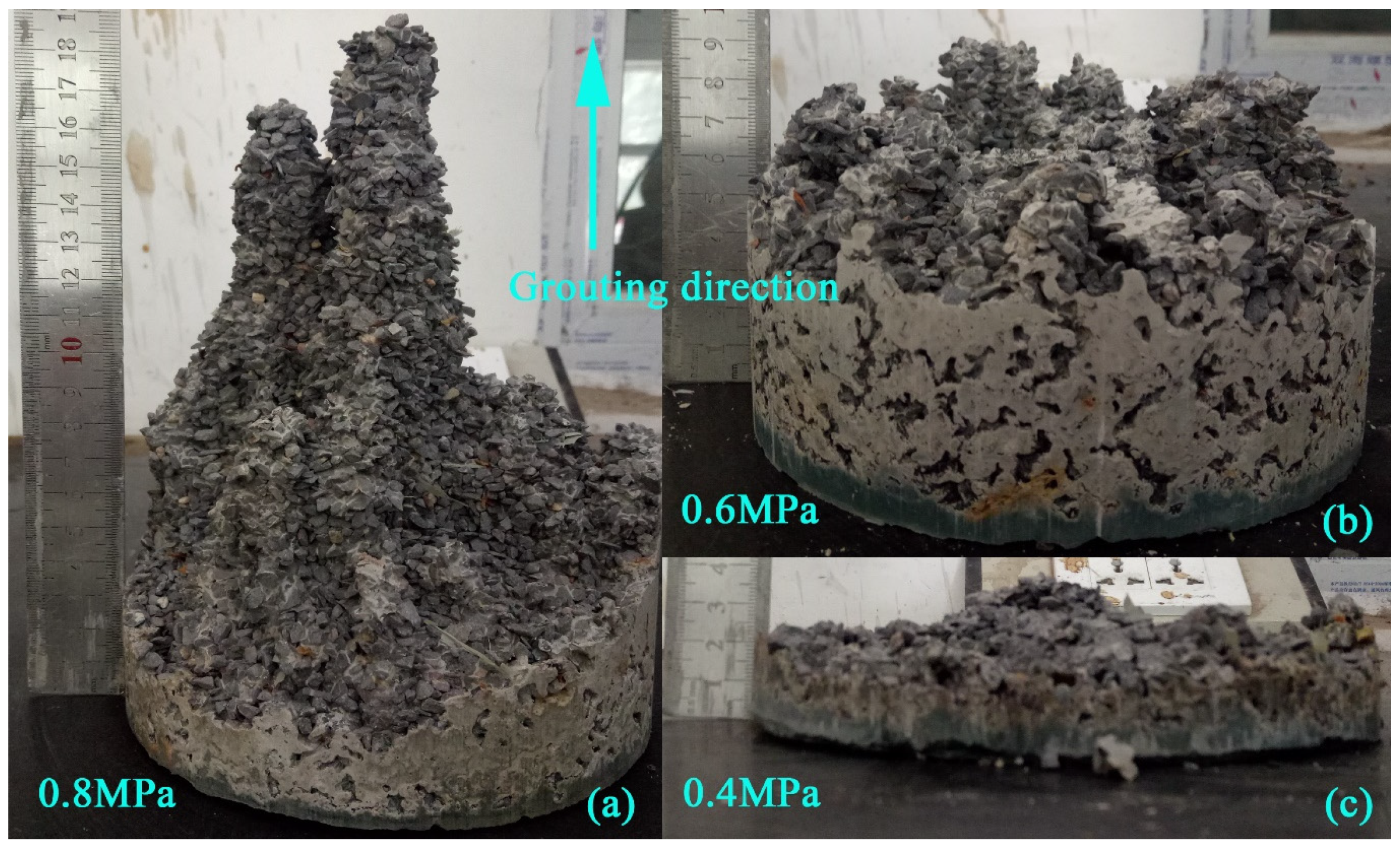
3.2. Single-Gradation 4.75–2.36 mm Grouting Test

When the particle size of the grouting aggregate was 4.75–2.36 mm, under the grouting pressure of 0.8 MPa, 0.6 MPa, and 0.4 MPa, the geopolymer slurry did not form a complete specimen. As shown in Figure 5, after subtracting the reserved void area with a reserved thickness of 10 mm, when the grouting pressure was 0.8 MPa, the diffused and solidified depth of the slurry at different positions of the specimen was 20 mm to 65 mm, and there were slurry veins at the center of the specimen. When the grouting pressure was 0.6 MPa, the slurry diffused and solidified the aggregate at a depth of 45 mm, and the development of slurry veins was relatively small. At a grouting pressure of 0.4 MPa, the slurry diffused and solidified the aggregate at a depth of 15 mm, and there was a hemispherical grout bulb in the center of the specimen, with almost no slurry veins developed.
It could be seen in Figure 6 that, under a grouting pressure of 0.8 MPa, the aggregate with a particle size of 4.75–2.36 mm formed an ellipsoidal slurry bulb with a core width of about 100 mm. As the slurry diffused, three independent slurry veins gradually formed with a top width of about 30 mm. The three slurry veins were all connected with the ellipsoidal slurry bulb and then developed independently downwards. Under grouting pressure, the geopolymer slurry diffused downwards in a columnar shape at the center of the specimen, ultimately forming multi-branched columnar slurry veins.
It could be seen in Figure 7 that, under a grouting pressure of 0.4 MPa, the aggregate with a particle size of 4.75–2.36 mm solidified by the geopolymer slurry had a thinner thickness and a smaller slurry bulb, and there was still some consolidated aggregate on the bottom flange plate of the test mold. Due to the relatively low grouting pressure and small voids between the aggregate, there was a significant pressure filtration effect in the grouting process. Due to the low amount of geopolymer slurry diffused to the bottom flange plate of the test mold, the consolidation of the aggregate was poor. It was shown that, when the porosity was small, the geopolymer slurry would produce a certain pressure filtration effect during the grouting process.

3.3. Single-Gradation 2.36–1.18 mm Grouting Test

When the particle size of the grouting aggregate was 2.36–1.18 mm, under grouting pressures of 0.8 MPa, 0.9 MPa, and 1.0 MPa, the geopolymer grouting test did not form a complete specimen. As shown in Figure 8, under the three grouting pressures, the consolidation depth of the slurry was very small.
The top view and front view of consolidated specimens with particle sizes of 2.36–1.18 mm are shown in Figure 9. Under grouting pressures of 0.8 MPa, 0.9 MPa, and 1.0 MPa, the consolidation depths of the geopolymer slurry for the 2.36–1.18 mm aggregate were 10 mm, 12 mm, and 15 mm, respectively, subtracting the reserved 10 mm thickness void area. At the center of the specimens, hemispherical slurry bulbs were formed, but the sizes were small. The maximum widths of the slurry bulbs were 60 mm, 70 mm, and 90 mm, respectively, with almost no development of slurry veins. Due to the small porosity of the aggregates, the diffusion of the geopolymer slurry was affected. Meanwhile, because the grouts squeezed the aggregate, the compactness was improved, and the diffusion of the grout was further weakened. After grouting completion, the remaining consolidated aggregate and geopolymer slurry on the bottom flange are shown in Figure 10. The pressure filtration effect of grouting with the 2.36–1.18 mm aggregate was more obvious. The consolidation strength of the aggregate at the bottom of the specimen was low under all three pressure conditions. When the pressure was 1.0 MPa, there was more residual geopolymer slurry on the bottom flange plate of the specimen, and the increase in grouting pressure further promoted the diffusion of the slurry.

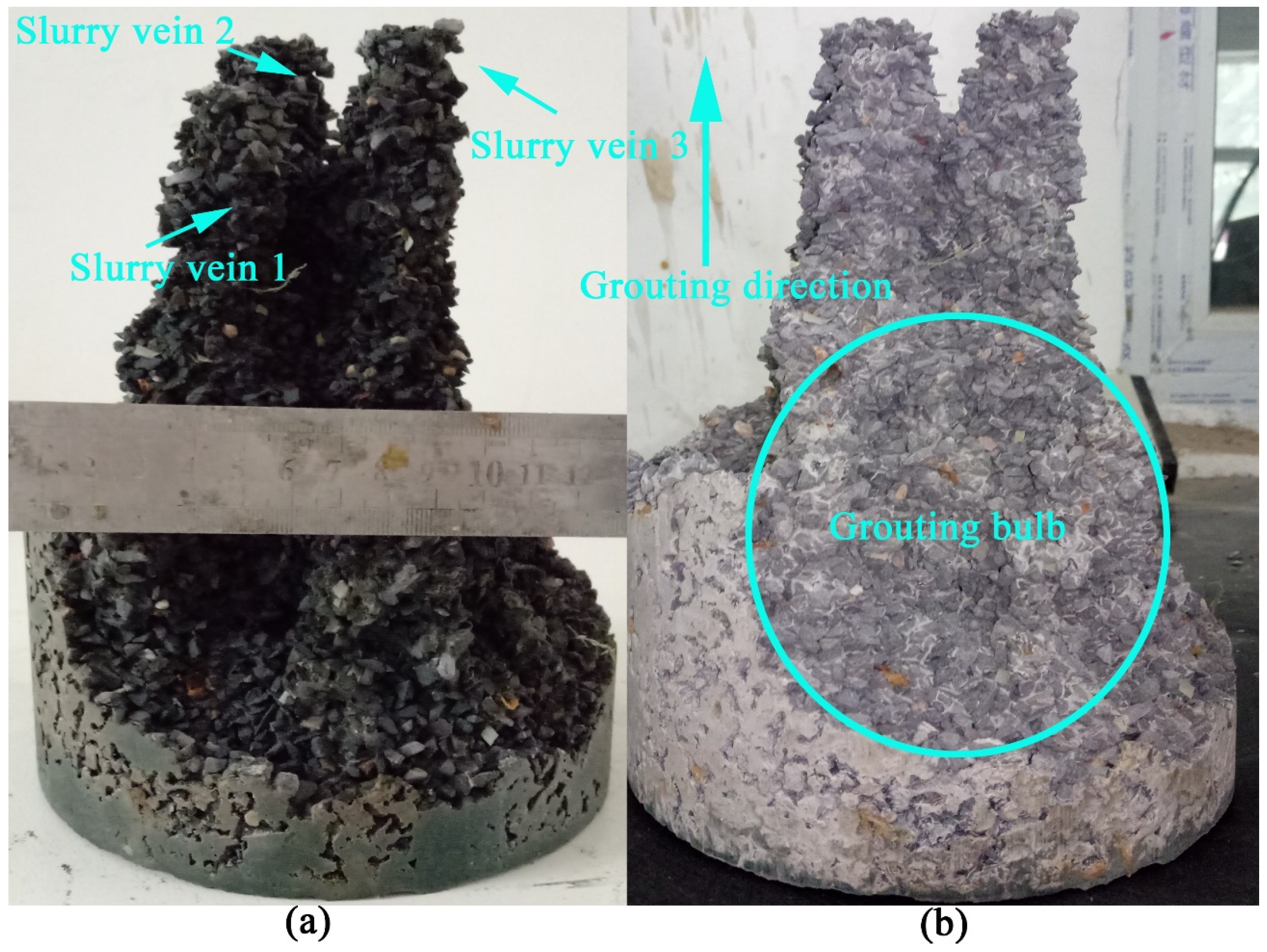
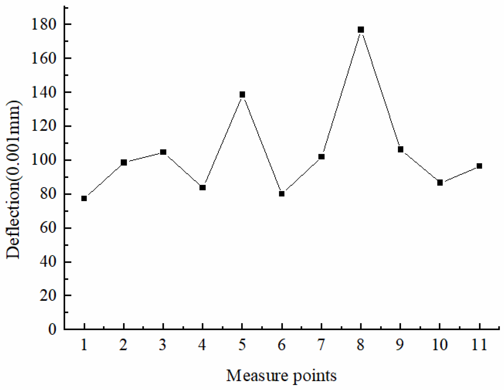
3.4. Diffusion and Consolidation Test

For studying the consolidated strength of aggregates with different particle sizes of 9.5–4.75 mm, 4.75–2.36 mm, and 2.36–1.18 mm after diffusion, the three single-graded aggregate grouting tests were conducted under different initial conditions. Slightly different from the previous grouting tests, the bottom flange plate valve of the test mold was first opened, and then the air pump valve was opened for grouting. The valve at the bottom of the mold was immediately closed when the slurry flowed out. We started timing after closing, and the grouting test ended after 1 min. Among the three types of single-graded aggregate, complete cylindrical specimens with the sizes of 4.75–2.36 mm, and 2.36–1.18 mm were not consolidated and formed, while only the 9.5–4.75 mm-particle-size aggregate consolidated and formed complete cylindrical specimens.
The consolidation specimen of the 4.75–2.36 mm aggregate under 0.8 MPa pressure is shown from the front view and top view, as shown in Figure 11. In the consolidation test of the aggregate with a 4.75–2.36 mm particle size, the complete cylindrical specimen was not consolidated, but the diffusion depth was 80 mm, and the slurry bulb appeared ellipsoidal. There were also many slurry veins at the lower part of the slurry bulb. In addition to the multiple veins in the center, there were also multiple slurry veins on the outer cylindrical surface of the specimen, with a diameter of about 30 mm. Since the bottom valve was opened at the beginning, the diffusion resistance of the geopolymer slurry was relatively low, resulting in an increase in the depth of diffusion and consolidation, as well as an increase in the number of grout veins. It could be seen in Figure 12 that the aggregate with a 2.36–1.18 mm particle size also did not solidify into a complete cylindrical specimen. The consolidation depth of the slurry was about 15 mm, and the slurry bulb was still very small, with a maximum diameter of 90 mm. Because the internal porosity of the aggregate with a 2.36–1.18 mm particle size was small, even if the bottom flange valve was open at the beginning, under high grouting pressure conditions, the influence on the diffusion depth of the slurry was still very small.
The consolidated specimens of the 9.5–4.75 mm aggregates and the 28 d compressive strength are shown in Figure 13. The aggregate with a 9.5–4.75 mm particle size was consolidated into complete cylindrical specimens under pressures of 0.2 MPa, 0.3 MPa, and 0.4 MPa. When the grouting pressure was 0.4 MPa and 0.3 MPa, the surface of the specimen was relatively smooth. However, when the pressure was 0.2 MPa, the structure of the bottom of the specimen was loose with some pores. It could be seen that, as the grouting pressure decreased, the compactness of the consolidated specimen gradually decreased. The basic principle of the compressive strength test was based on “Testing Methods of Cement and Concrete for Highway Engineering” (JTG 3420-2020) [33]. Under the three grouting pressures, the 28 d compressive strength of the 0.4 MPa grouting specimen was the highest, while the 28 d compressive strength of the 0.3 MPa grouting specimen was the second highest, and the 28 d compressive strength of the 0.2 MPa grouting specimen was the smallest. Although the 28 d compressive strength of the 0.2 MPa grouting specimen was the lowest, it was still higher than that of the geopolymer slurry with a water–slag ratio of 0.4. It could be seen that the geopolymer slurry had a good consolidation performance for the loose aggregate. Through drilling, it was found that, in the concrete pavement rehabilitation using micro-cracking homogenization, in the local weak roadbed sections, the loose aggregates are mostly fine aggregates, with a few slightly larger-particle-size aggregates. The diffusion and consolidation characteristics are fully demonstrated, which provides a certain guidance for the actual grouting construction scheme on site.

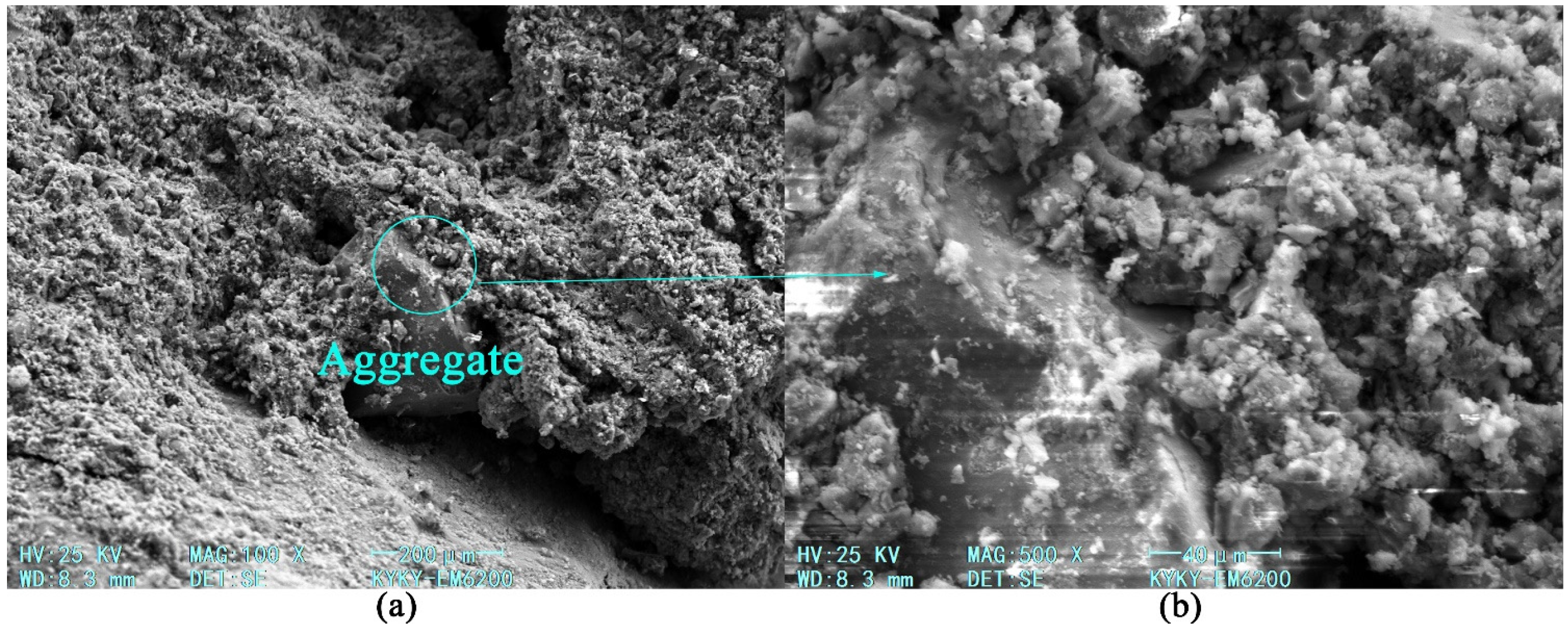
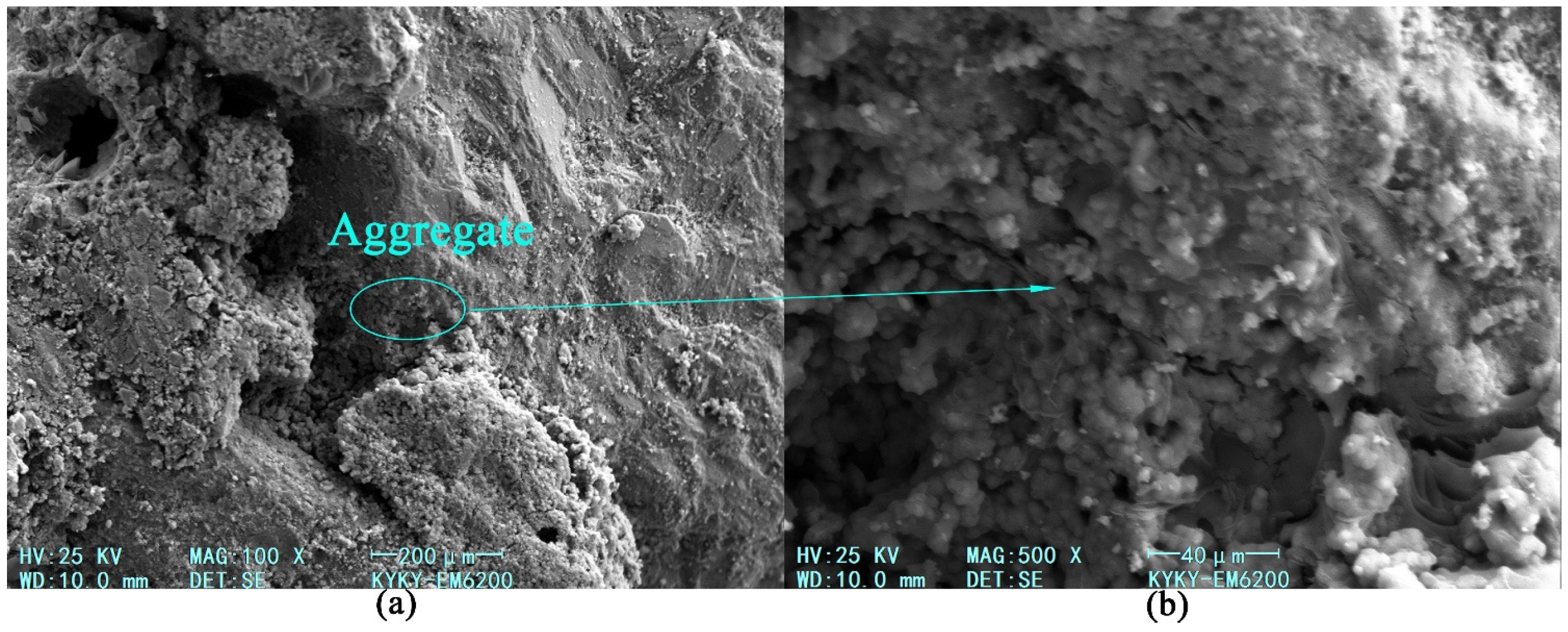
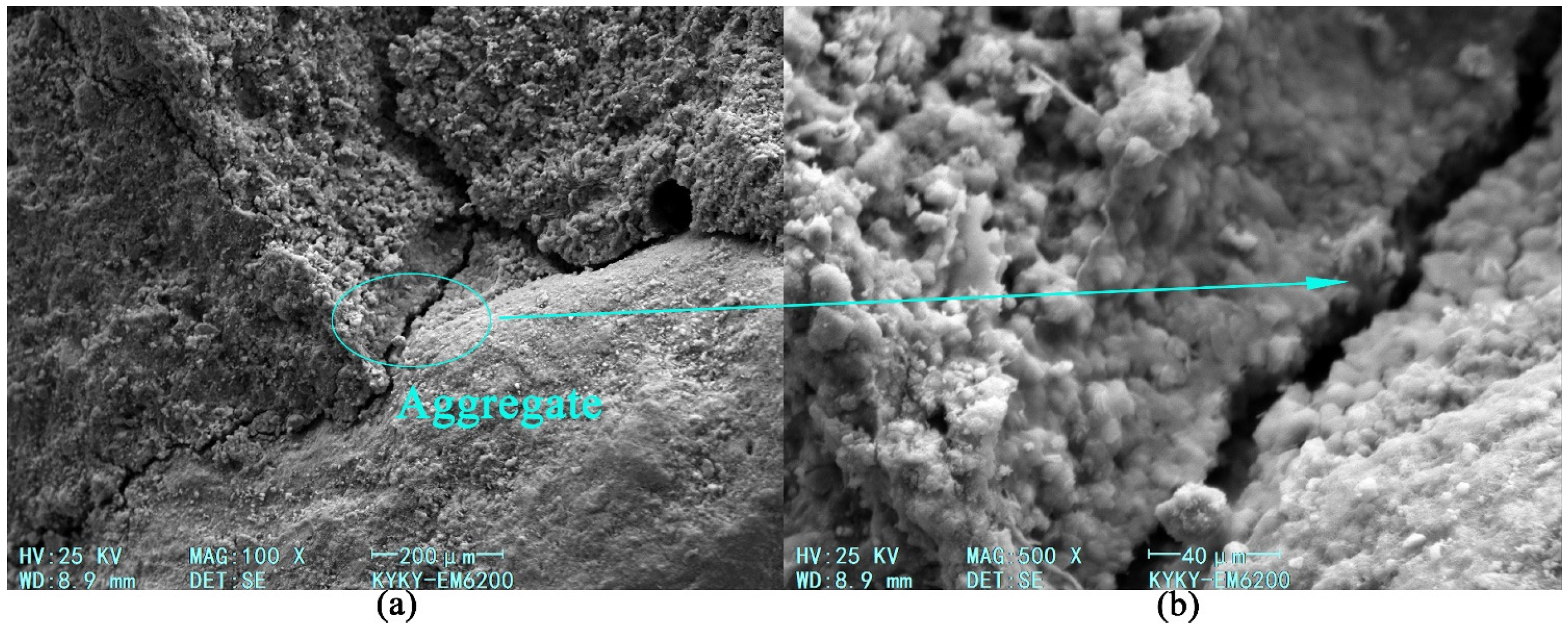
3.5. Microscopic Test

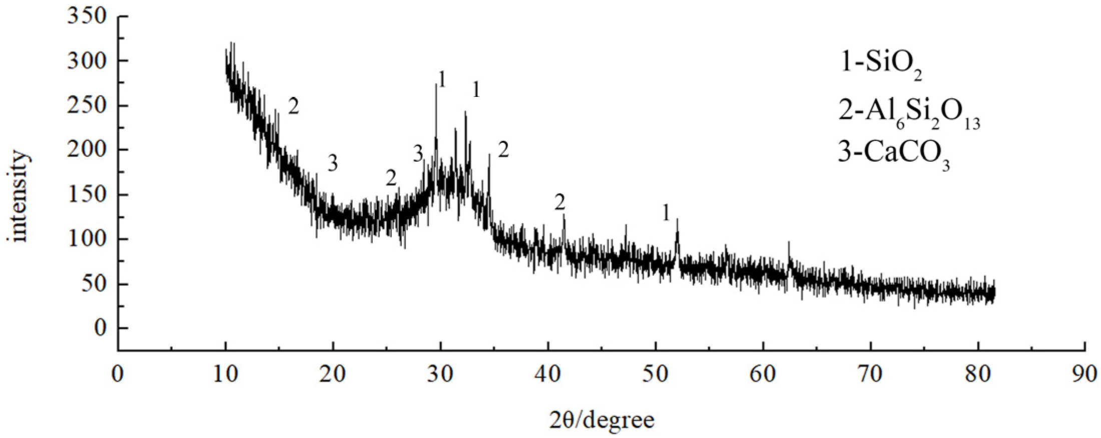
3.5.1. Microscopic Morphology and Reactants of Geopolymer Slurry

The microstructure and reactants of the slag-based geopolymer were observed under 100×, 500×, 1000×, and 2000× magnification, as shown in Figure 14. In Figure 14a, under 100× magnification, due to the slightly higher water content of the geopolymer slurry, the hydration and dissolution reaction were promoted, but the pores of the structure increased and the density of the structure decreased. In Figure 14b, under 500× magnification, it could be seen that the slag-based geopolymer had a little shrinkage, and shrinkage cracks appeared locally on the surface of the geopolymer, but the size was not large. In Figure 14c, under 1000× magnification, the reactants of the geopolymer material were mainly gel-phase material, but, due to the slightly higher water content, the density of the local geopolymer was slightly lower. In Figure 14d, under 2000× magnification, the polymerization reaction of the geopolymer was relatively complete, and no unreacted sheet-like calcium hydroxide crystals were observed.
The types and contents of elements in the geopolymer reactants were analyzed using EDS by selecting geopolymer samples from the consolidated core area. The SEM images and EDS spectra under 1000× magnification are shown in Figure 15, Figure 16 and Figure 17. It could be seen that a large number of gel-phase products were generated, mainly C-S-H gel. There were micro-cracks on the surface of the slag-base geopolymer locally, but, as the particle size and porosity of the aggregate increased, the consolidation of the geopolymer slurry became better. From the EDS spectrum, it could be seen that the main elements in the hydration products of the slag-based geopolymer were Ca, Si, Al, Mg, C, O, etc.

3.5.2. Microscopic Analysis of Consolidation Characteristics

In order to further study the consolidation characteristics of the geopolymer slurry of the aggregate with different particle sizes, samples were taken from the core area of the slurry bulbs of specimens with three single-graded aggregates of 9.5–4.75 mm, 4.75–2.36 mm, and 2.36–1.18 mm under grouting pressures of 0.4 MPa, 0.8 MPa, and 1.0 MPa, respectively. The microstructure of the consolidated slurry was observed by SEM.
As shown in Figure 18, under the condition of a 1.0 MPa grouting pressure for the aggregate with a 2.36–1.18 mm particle size, the aggregate was wrapped by the geopolymer slurry. Because the porosity of the 2.36–1.18 mm aggregate was small, the diffusion of the slurry between the aggregate was affected. The consolidated slurry-wrapped aggregate was slightly loose, and there were many granular gels on the surface of the consolidated slurry. As shown in Figure 19, under a grouting pressure of 0.8 MPa, the pores of the aggregate with a 4.75–2.36 mm particle size were filled with the geopolymer slurry. The increase in the porosity of the aggregate facilitated the diffusion of the geopolymer slurry, resulting in a denser structure after consolidation. Cracks appeared locally at the bonding interface between the aggregate and geopolymer slurry, but the width of the cracks was still very small. As shown in Figure 20, under a grouting pressure of 0.4 MPa, with a further increase in aggregate pores, the diffusion of the slurry in the pores was better and the density of the consolidated slurry was the highest for the aggregate with particle sizes of 9.5–4.75 mm. Due to the relatively large particle size of the aggregate, its bonding interface with the geopolymer slurry was also larger, and the shrinkage of the slag–geopolymer bonding interface was also greater. Compared with the fine aggregate, the interface cracks were relatively wider.

4. Practical Application

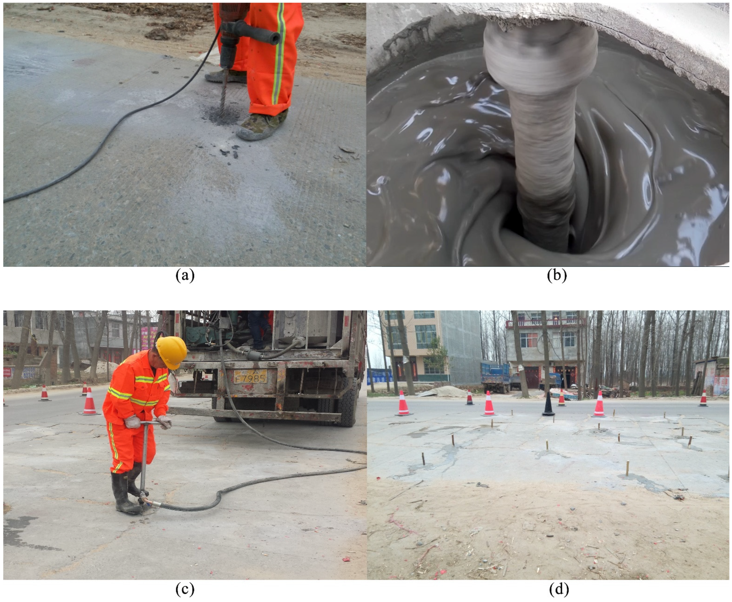
4.1. Grouting Operation

After the homogenization of the old concrete pavement, the asphalt mixture can be directly overlaid, but local road base diseases can cause reflective cracks in the new asphalt pavement. In order to prevent the occurrence of reflective cracks on the asphalt pavement, it is necessary to know the condition of road base diseases, so as to conduct reinforcement by grouting. The FWD deflection detection method was used on site. By comparing the deflection values of adjacent measuring points, the types of road voids or weak base diseases were preliminarily determined. The deflection values of the test section are shown in Figure 21. To further determine the type of disease, ground penetrating radar was used to detect the abnormal points of deflection, as shown in Figure 22. It was found that the disease at the location of the abnormal deflection was a loose base. Therefore, grouting reinforcement was first carried out on the identified location of the disease to stabilize the road base structure layer.
In order to treat the local weak road base diseases of the concrete pavement, the new geopolymer grouting material was used for grouting reinforcement. Based on field investigations and incorporating the diffusion and consolidation characteristics of the geopolymer obtained from indoor grouting tests, the on-site grouting scheme was formulated. The on-site grouting operation is shown in Figure 23. The grouting hole was drilled using a hand drill with a depth of 1 m and a space of 1 m, and then the geopolymer slurry was prepared. The slurry needed to be mixed in a mixing bucket. The grouting pipe was inserted into the hole. We started grouting and observed whether the grouting pressure reached the maximum value of 1.25 MPa, as well as whether there was the concrete slab lifting phenomenon. If there was grout leakage from adjacent holes or if the concrete slab was lifted by more than 1.5 mm, we stopped the grouting operation and used wooden plugs to seal the holes. After the grouting of the geopolymer was completed, traffic could be opened after a short period of maintenance.

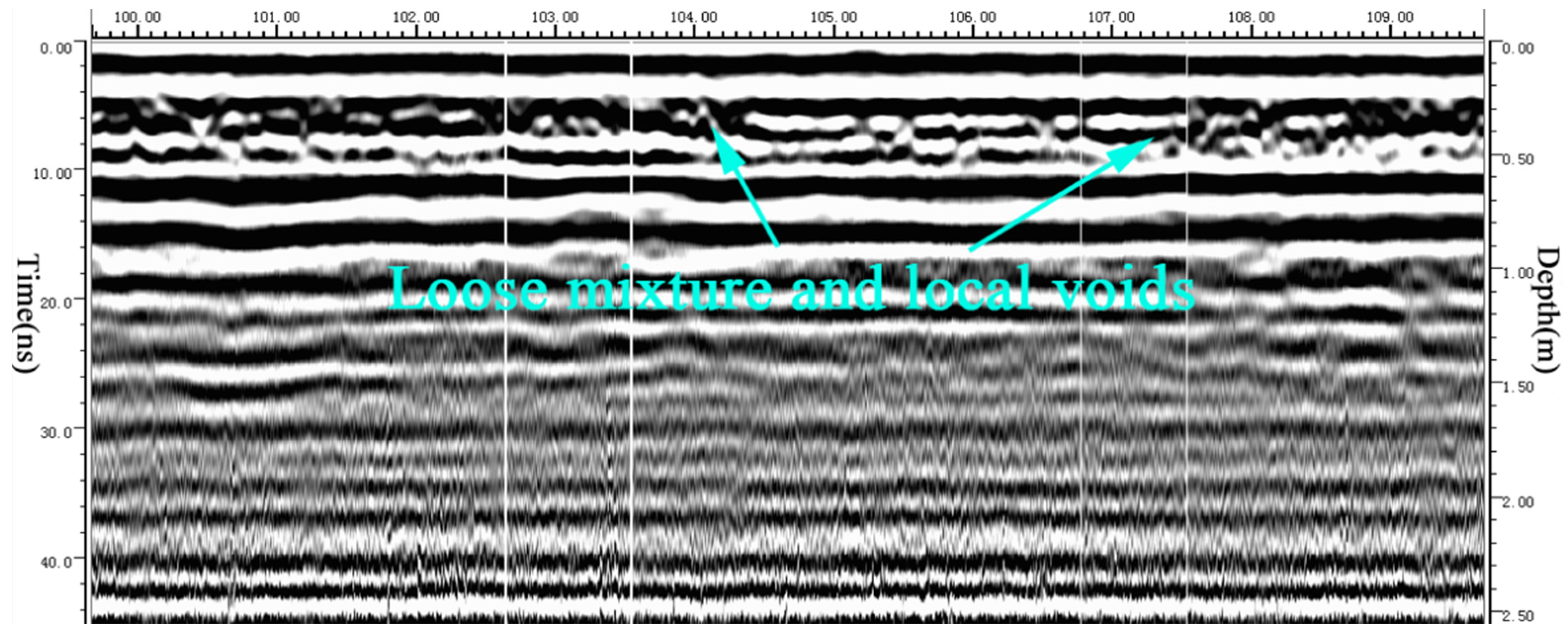
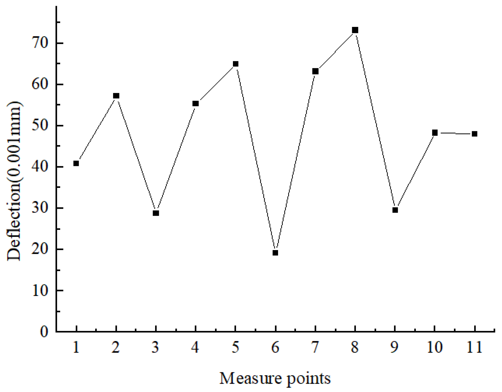
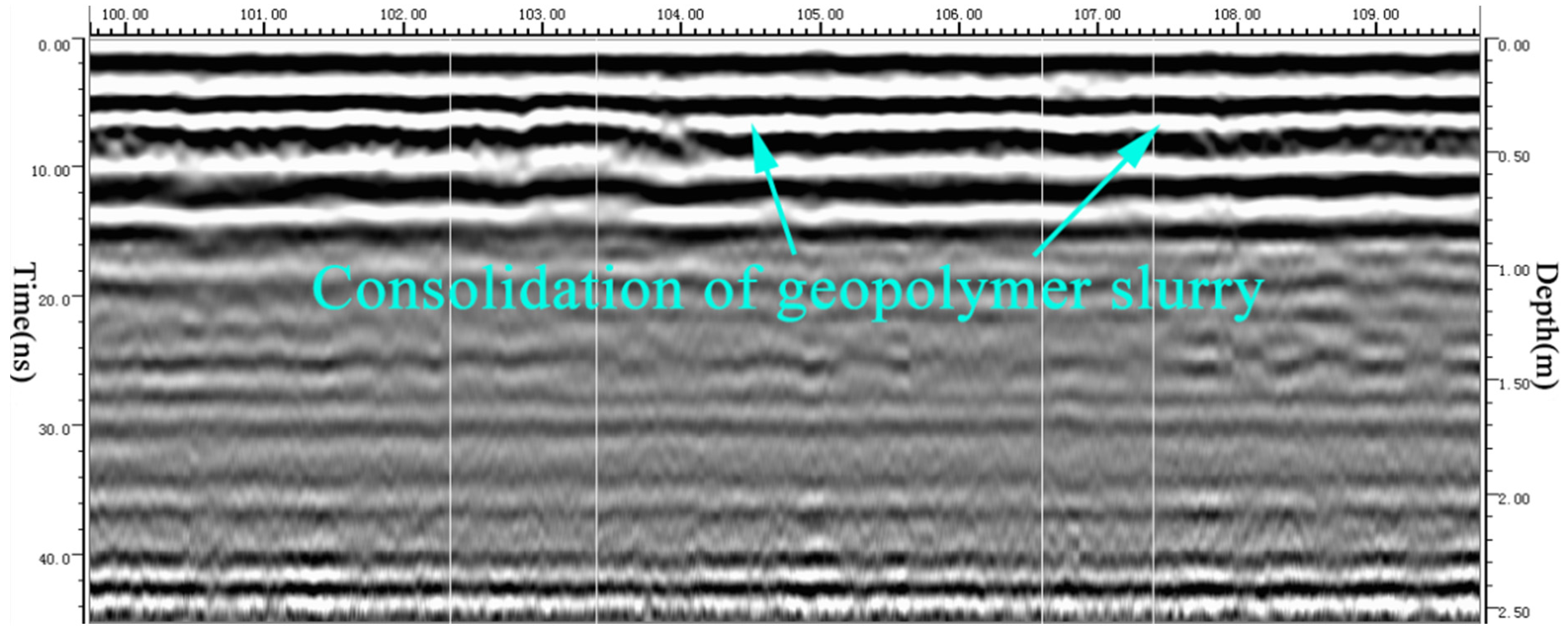
4.2. Grouting Consolidation Effect

After grouting, the deflection values of local disease locations significantly decreased, and the dispersion of deflection values decreased. The monitoring section deflection after grouting is shown in Figure 24. The average deflection value decreased from 104.8 (0.001 mm) to 48 (0.001 mm), indicating that the weak base disease of the road has been effectively treated. The radar detection of the road structure layers of the driveway after grouting is shown in Figure 25. The loose aggregate in the road base was consolidated, and the slurry formed a layered structure after consolidation, making the road base structure layer denser.
It could be seen in Figure 26 that, through the excavation of the test pit, it was found that the geopolymer slurry effectively filled the voids under the concrete slab and the interlayer gaps of each road base layer. For loose road base layers, the geopolymer slurry played a good role in consolidation. After solidification, the geopolymer slurry formed a layered distribution, further compacted the road base layer, and enhanced the overall bearing capacity of the road base.

5. Conclusions

A new visual indoor grouting test system was developed to study the diffusion and consolidation characteristics of the slag-based geopolymer under different gradation aggregate conditions, and SEM was used to observe the reactants and consolidation. Moreover, the consolidation effect of the slag-based geopolymer on a weak road base was studied through on-site grouting tests. The main conclusions are as follows:
As the size of the aggregate decreased, the diffusion depth of the slurry gradually decreased, and a relatively complete specimen only formed at a high grouting pressure. The 9.5–4.75 mm aggregate formed a complete cylindrical specimen under a grouting pressure of 0.4 MPa; when the grouting pressure was 0.2 MPa, 20 mm to 50 mm grout splitting surfaces would form at the lower part of the grout bulb. However, the 4.75–2.36 mm aggregate only developed a bulb and some slurry veins, and a pressure filtration effect occurred. The 2.36–1.18 mm aggregate did not develop slurry veins, and the grouting bulb was also very small; moreover, the pressure filtration effect was more significant. In the diffusion consolidation grouting test, the strength of the specimens consolidated by the 9.5–4.75 mm aggregate met the requirement of 28 d strength, and the diffusion depth of the other two aggregates also increased.
Due to the fact that the blast furnace slag powder was rich in CaO and SiO2, a large number of gel products were generated by the polymerization of geopolymer materials. The geopolymer slurry with a water–slag ratio of 0.4 would promote the hydration and dissolution reaction in the early stage, but the pores of the structure would increase, and shrinkage cracks appeared in local positions of the reactants. However, the size of the cracks was not large, and the polymerization reaction of the geopolymer was relatively complete, without any residual flake-shaped calcium hydroxide crystals.
As the size and porosity of the aggregate increased, the diffusion depth of the geopolymer slurry also increased, resulting in a better consolidation effect on the aggregate. Under a 1.0 MPa grouting pressure, the consolidated 2.36–1.18 mm aggregate was slightly loose, and there were many granular gels on the surface. Under a 0.8 MPa grouting pressure, the geopolymer filled the pores of the 4.75–2.36 mm aggregate, and the consolidated structure was relatively dense. Fine cracks appeared locally at the bonding interface between the aggregate and the slurry. Under a 0.4 MPa grouting pressure, the diffusion of the slurry in the pores of the 9.5–4.75 mm aggregate was better, and the solidified slurry was denser. The slurry consolidated coarse aggregate shrank slightly, and the interface cracks were relatively wider compared to the fine aggregate, but it could still meet the actual engineering needs.
The diffusion and consolidation characteristics of the geopolymer obtained through indoor tests provide a certain guidance for the formulation of on-site grouting schemes. The geopolymer slurry effectively penetrated the voids beneath the concrete slabs and within the road base layers, enhancing the overall structural stability. The average deflection of the driveway decreased from 104.8 (0.001 mm) to 48 (0.001 mm). The geopolymer materials consolidated quickly, and generated dense fillers between the weak road base layers, which could significantly improve the road base load-bearing capacity.

Author Contributions

Conceptualization, W.L. and B.L.; methodology, J.Y.; software, W.L.; validation, W.L. and B.L.; formal analysis, W.L.; investigation, J.Y.; resources, B.L.; data curation, W.L.; writing—original draft preparation, W.L.; writing—review and editing, B.L.; visualization, W.L.; supervision, W.L.; project administration, J.Y.; funding acquisition, B.L. All authors have read and agreed to the published version of the manuscript.

Funding

This research was funded by the Project of Science and Technology of Henan Transportation Department (Grant numbers 2018J4 and 2019J1).

Institutional Review Board Statement

Not applicable.

Informed Consent Statement

Not applicable.

Data Availability Statement

The original contributions presented in this study are included in the article. Further inquiries can be directed to the corresponding author.

Acknowledgments

We gratefully acknowledge the financial support from the Project of Science and Technology of Henan Transportation Department.

Conflicts of Interest

The authors declare no conflicts of interest.

References

  1. Li, W.J.; Zhang, Q.L.; Zhi, Z.H.; Feng, C.; Cai, Y.C.; Yue, J.C. Investigation on the fracture mechanism of homogenized micro-crack crushing technology for portland cement concrete pavement rehabilitation. AIP Adv. 2019, 9, 075113. [Google Scholar] [CrossRef]
  2. Li, W.J.; Guo, Y.; Liang, B.; Yue, J.C. A Numerical Study on the Crack Propagation of Homogenized Micro-Crack Crushing for Concrete Pavement. Appl. Sci. 2022, 12, 7114. [Google Scholar] [CrossRef]
  3. Huynh, A.T.; Magee, B.; Woodward, D. A Preliminary Characterisation of Innovative Semi-Flexible Composite Pavement Comprising Geopolymer Grout and Reclaimed Asphalt Planings. Materials 2020, 13, 3644. [Google Scholar] [CrossRef]
  4. Xu, J.; Kang, A.H.; Wu, Z.G.; Xiao, P.; Li, B.; Lu, Y.M. Research on the Formulation and Properties of a High-Performance Geopolymer Grouting Material Based on Slag and Fly Ash. KSCE J. Civ. Eng. 2021, 25, 3437–3447. [Google Scholar] [CrossRef]
  5. Zhou, S.Q.; Yang, Z.N.; Zhang, R.R.; Li, F. Preparation, characterization and rheological analysis of eco-friendly road geopolymer grouting materials based on volcanic ash and metakaolin. J. Clean. Prod. 2021, 312, 127822. [Google Scholar] [CrossRef]
  6. Xu, J.; Kang, A.H.; Wu, Z.G.; Xiao, P.; Gong, Y.F. Effect of high-calcium basalt fiber on the workability, mechanical properties and microstructure of slag-fly ash geopolymer grouting material. Constr. Build. Mater. 2021, 302, 124089. [Google Scholar] [CrossRef]
  7. Zhang, Y.; Wang, Y.; Wu, Z.G.; Lu, Y.M.; Kang, A.H.; Xiao, P. Optimal design of geopolymer grouting material for semi-flexible pavement based on response surface methodology. Constr. Build. Mater. 2021, 306, 124779. [Google Scholar] [CrossRef]
  8. Li, S.C.; Zhang, J.; Li, Z.F.; Gao, Y.F.; Liu, C. Feasibility study of red mud-blast furnace slag based geopolymeric grouting material: Effect of superplasticizers. Constr. Build. Mater. 2021, 267, 120910. [Google Scholar] [CrossRef]
  9. Güllü, H.; Agha, A.A. The rheological, fresh and strength effects of cold-bonded geopolymer made with metakaolin and slag for grouting. Constr. Build. Mater. 2021, 274, 122091. [Google Scholar] [CrossRef]
  10. Li, Z.F.; You, H.; Gao, Y.F.; Wang, C.A.; Zhang, J. Effect of ultrafine red mud on the workability and microstructure of blast furnace slag-red mud based geopolymeric grouts. Powder Technol. 2021, 392, 610–618. [Google Scholar] [CrossRef]
  11. Tian, Z.N.; Liu, X.; Zhang, Z.Q.; Zhang, K.W.; Tang, X.M. Potential using of water-soluble polymer latex modified greener road geopolymeric grouts: Its preparation, characterization and mechanism. Constr. Build. Mater. 2021, 273, 121757. [Google Scholar] [CrossRef]
  12. Guo, L.Z.; Zhou, M.; Wang, X.Y.; Li, C.; Jia, H.Q. Preparation of coal gangue-slag-fly ash geopolymer grouting materials. Constr. Build. Mater. 2022, 328, 126997. [Google Scholar] [CrossRef]
  13. Li, L.; Wei, Y.J.; Li, Z.L.; Farooqi, M.U. Rheological and viscoelastic characterizations of fly ash/slag/silica fume-based geopolymer. J. Clean. Prod. 2022, 354, 131629. [Google Scholar] [CrossRef]
  14. Kantarci, F.; Maras, M.M. Fabrication of Novel Geopolymer Grout as Repairing Material for Application in Damaged RC Beams. Int. J. Civ. Eng. 2022, 20, 461–474. [Google Scholar] [CrossRef]
  15. Guo, Y.C.; Huang, Y.L.; Li, J.M.; Ouyang, S.Y.; Fan, B.T.; Liu, Y.H.; Hou, G.F. Preparation of the geopolymer grouting material by coal-based solid wastes for the aquiclude key strata and its application. Constr. Build. Mater. 2023, 408, 133539. [Google Scholar] [CrossRef]
  16. Duan, D.D.; Wu, H.B.; Wei, F.; Song, H.P.; Chen, Z.; Cheng, F.Q. Preparation, characterization, and rheological analysis of eco-friendly geopolymer grouting cementitious materials based on industrial solid wastes. J. Build. Eng. 2023, 78, 107451. [Google Scholar] [CrossRef]
  17. Yang, Z.N.; Zhou, S.Q.; Li, F.; Zhang, R.R.; Zhu, X.Y. Preparation and rheological performance analysis of volcanic ash and metakaolin based geopolymer grouting materials. Road Mater. Pavement 2023, 24, 1614–1635. [Google Scholar] [CrossRef]
  18. Wei, J.; Liu, J.S.; Zhang, M.; Feng, B.W.; Chen, Y.H.; Wang, L.; Wang, Z.; Fu, W.W.; Peng, H.; Lu, H.J.; et al. Effects of Steel Slag and Flue Gas Desulfurization Gypsum on the Properties of Metakaolin-Based Geopolymer Grouting Materials. J. Test. Eval. 2023, 51, 3900–3916. [Google Scholar] [CrossRef]
  19. Li, W.J.; Liang, B.; Yue, J.C. Mechanical Properties of Slag-Based Geopolymer Grouting Material for Homogenized Micro-Crack Crushing Technology. Appl. Sci. 2023, 13, 8353. [Google Scholar] [CrossRef]
  20. Li, F.; Yang, Z.N.; Zhou, S.Q.; Zhang, X.; Liu, D.Y.; Su, Y.J.; Niu, Q. Fly-ash-based geopolymer modified by metakaolin for greener grouting material. Proc. Inst. Civ. Eng.-Eng. Sustain. 2023, 177, 125–138. [Google Scholar] [CrossRef]
  21. Zhang, J.; Gao, Y.F.; Li, Z.F.; Wang, C. Pb2+ and Cr3+ immobilization efficiency and mechanism in red-mud-based geopolymer grouts. Chemosphere 2023, 321, 138129. [Google Scholar] [CrossRef]
  22. Li, X.F.; Feng, X.T.; Zhou, Y.Y.; Yang, C.X.; Liu, X.F. Formulation and properties of a new cleaner double liquid alkali-activated grouting material. J. Clean. Prod. 2023, 426, 138878. [Google Scholar] [CrossRef]
  23. Souayfan, F.; Rozière, E.; Loukili, A.; Justino, C. Effect of Retarders on the Reactivity and Hardening Rate of Alkali-Activated Blast Furnace Slag Grouts. Materials 2023, 16, 5824. [Google Scholar] [CrossRef] [PubMed]
  24. Güllü, H.; Yetim, M.E.; Güllü, E.B. On the rheological, fresh and strength effects of using nano-silica added geopolymer grout for grouting columns. Eur. J. Environ. Civ. Eng. 2024, 28, 1183–1207. [Google Scholar] [CrossRef]
  25. Wang, X.C.; Xiao, F.; Zhang, Q.S.; Zhou, A.N.; Liu, R.T. Grouting characteristics in rock fractures with rough surfaces: Apparatus design and experimental study. Measurement 2021, 184, 109870. [Google Scholar] [CrossRef]
  26. Liu, B.; Sang, H.M.; Liu, Q.S.; Liu, H.; Pan, Y.C.; Kang, Y.S. Laboratory Study on Diffusion and Migration of Grout in Rock Mass Fracture Network. Int. J. Geomech. 2021, 21, 04020242. [Google Scholar] [CrossRef]
  27. Hao, M.M.; Li, X.L.; Zhong, Y.H.; Zhang, B.; Wang, F.M. Experimental Study of Polyurethane Grout Diffusion in a Water-Bearing Fracture. J. Mater. Civ. Eng. 2021, 33, 04020485. [Google Scholar] [CrossRef]
  28. Han, C.H.; Wei, J.C.; Zhang, W.J.; Yang, F.; Yin, H.Y.; Xie, D.L.; Xie, C. Quantitative permeation grouting in sand layer with consideration of grout properties and medium characteristics. Constr. Build. Mater. 2022, 327, 126947. [Google Scholar] [CrossRef]
  29. Zhu, H.X.; Han, L.J. Experimental Study on Grouting Seepage Characteristics of Single-Fractured Rock Masses with Different Inclination Angles under Three-Dimensional Stress. Geofluids 2022, 2022, 1491385. [Google Scholar] [CrossRef]
  30. Hu, H.X.; Gan, B.Q.; Deng, C.; Xie, Z.L.; Lu, Y.F.; Cai, Y.H. Experimental study on the effect of water-cement ratios on the diffusion behavior of sand soil grouting. Bull. Eng. Geol. Environ. 2024, 83, 80. [Google Scholar] [CrossRef]
  31. Li, G.S.; Li, Z.H.; Du, F.; Cao, Z.Z.; Wang, W.Q. Development of Grouting Test System for Rough Fissure Rock Body and Research on Slurry Diffusion Law. Appl. Sci. 2024, 14, 47. [Google Scholar] [CrossRef]
  32. Hu, Y.; Liu, W.Q.; Ma, T.R. Study on visual simulation experiment of water-displacing grouting in fractured aquifer. Environ. Earth Sci. 2024, 83, 4. [Google Scholar] [CrossRef]
  33. JTG 3420-2020; Testing Methods of Cement and Concrete for Highway Engineering. China Communications Press: Beijing, China, 2020.
  34. JTG 3432-2824; Test Methods of Aggregates for Highway Engineering. China Communications Press: Beijing, China, 2024.
Figure 1. XRD of blast furnace slag powder.
Applsci 15 04373 g001
Figure 2. Grouting test system: (a) schematic diagram; and (b) assembled grouting test system.
Applsci 15 04373 g002
Figure 3. Consolidated specimens with particle sizes of 9.5–4.75 mm.
Applsci 15 04373 g003
Figure 4. Slurry diffusion morphology of 9.5–4.75 mm aggregate under 0.2 MPa pressure: (a) front; and (b) top.
Applsci 15 04373 g004
Figure 5. Consolidated specimens with particle sizes of 4.75–2.36 mm: (a) 0.8 MPa; (b) 0.6 MPa; and (c) 0.4 MPa.
Applsci 15 04373 g005
Figure 6. Slurry diffusion morphology of 4.75–2.36 mm aggregate under 0.8 MPa pressure: (a) the development of slurry veins; and (b) the development of grouting bulb.
Applsci 15 04373 g006
Figure 7. Slurry diffusion morphology of 4.75–2.36 mm aggregate under 0.4 MPa pressure: (a) residual consolidated aggregate at the bottom flange; (b) undemolded specimen; and (c) demolded specimen.
Applsci 15 04373 g007
Figure 8. Consolidated specimens with particle sizes of 2.36–1.18 mm.
Applsci 15 04373 g008
Figure 9. Slurry diffusion morphology of 2.36–1.18 mm aggregate: (a) 0.8 MPa; (b) 0.9 MPa; and (c) 1.0 MPa.
Applsci 15 04373 g009
Figure 10. The pressure filtration effect of slurry using 2.36–1.18 mm aggregate: (a) 0.8 MPa; (b) 0.9 MPa; and (c) 1.0 MPa.
Applsci 15 04373 g010
Figure 11. The consolidation specimen of 4.75–2.36 mm aggregate under 0.8 MPa pressure: (a) front view; and (b) top view.
Applsci 15 04373 g011
Figure 12. The consolidation specimen of 2.36–1.18 mm aggregate under 1.0 MPa pressure: (a) front view; and (b) top view.
Applsci 15 04373 g012
Figure 13. 28 d compressive strength of 9.5–4.75 mm aggregate consolidated specimens: (a) specimens consolidated under different grouting pressures; and (b) compressive strength of 28 d.
Applsci 15 04373 g013
Figure 14. The reactants and microstructure of slag-based geopolymer. (a) 100×; (b) 500×; (c) 1000×; and (d) 2000×.
Applsci 15 04373 g014
Figure 15. SEM image and EDS spectra of geopolymer-consolidated 2.36–1.18 mm aggregate: (a) SEM image; and (b) EDS spectra analysis.
Applsci 15 04373 g015
Figure 16. SEM image and EDS spectra of geopolymer-consolidated 4.75–2.36 mm aggregate: (a) SEM image; and (b) EDS spectra analysis.
Applsci 15 04373 g016
Figure 17. SEM image and EDS spectra of geopolymer-consolidated 9.5–4.75 mm aggregate: (a) SEM image; and (b) EDS spectra analysis.
Applsci 15 04373 g017
Figure 18. Bonding interface between 2.36–1.18 mm aggregate and geopolymer slurry: (a) 100×; and (b) 500×.
Applsci 15 04373 g018
Figure 19. Bonding interface between 4.75–2.36 mm aggregate and geopolymer slurry: (a) 100×; and (b) 500×.
Applsci 15 04373 g019
Figure 20. Bonding interface between 9.5–4.75 mm aggregate and geopolymer slurry: (a) 100×; and (b) 500×.
Applsci 15 04373 g020
Figure 21. Deflection of driveway before grouting.
Applsci 15 04373 g021
Figure 22. Radar detection of the road base layers of driveway before grouting.
Applsci 15 04373 g022
Figure 23. The on-site grouting operation: (a) drilling of grouting holes; (b) mixing of geopolymer slurry; (c) grouting operation; and (d) hole sealing.
Applsci 15 04373 g023
Figure 24. Deflection of driveway after grouting.
Applsci 15 04373 g024
Figure 25. Radar detection of the road structure layers of driveway after grouting.
Applsci 15 04373 g025
Figure 26. Test pit excavation for geopolymer grouting test: (a) consolidated slurry at the bottom of the slab; (b) consolidation slurry at the top of the road base; (c) exploration pit excavation; and (d) consolidation of loose granular materials and consolidated geopolymer slurry layer.
Applsci 15 04373 g026
Table 1. Composition of raw materials (wt.%).
MaterialCaOSiO2Al2O3MgOSO3TiO2FexOyNa2OK2OMnO
slag39.4626.0113.248.412.251.040.680.600.600.30
Table 2. The pore parameters of aggregate.
Particle Size (mm)PorosityDensity (g/cm3)
9.5–4.750.441.43
4.75–2.360.401.55
2.36–1.180.371.58
Table 3. The grouting test pressure.
Particle Size (mm)Grouting Pressure (MPa)
9.5–4.750.20.30.4
4.75–2.360.40.60.8
2.36–1.180.80.91
Disclaimer/Publisher’s Note: The statements, opinions and data contained in all publications are solely those of the individual author(s) and contributor(s) and not of MDPI and/or the editor(s). MDPI and/or the editor(s) disclaim responsibility for any injury to people or property resulting from any ideas, methods, instructions or products referred to in the content.

