Article

Mechanisms of Surrounding Rock Failure and Control Measures When Main Roof Fractures Directly Above Gob-Side Entry in Thick Coal Seam

1
School of Energy and Mining Engineering, China University of Mining and Technology-Beijing, Beijing 100083, China
2
Anhui Hengyuan Coal & Electric Co., Ltd., Huaibei 234011, China
3
Songxinzhuang Coal Mine, Ningxia 751504, China
4
School of Mechanical and Mining Engineering, The University of Queensland, St. Lucia, Brisbane 4072, Australia
5
Jizhong Energy Co., Ltd., Xingdong Mine, Xingtai 054000, China
*
Authors to whom correspondence should be addressed.
Appl. Sci. 2025, 15(8), 4284; https://doi.org/10.3390/app15084284
Submission received: 2 March 2025 / Revised: 3 April 2025 / Accepted: 9 April 2025 / Published: 13 April 2025
(This article belongs to the Section Earth Sciences)

Abstract

:
This study investigates the surrounding rock failure caused by the fracture line of the main roof above the gob-side roadway during fully mechanized top-coal caving mining in a 19 m thick coal seam. As mining progresses, stress concentration occurs in the roadway roof. Furthermore, the fracture line of the main roof above the roadway poses a significant threat to the structural stability of the gob-side roadway, leading to the localized failure of the roof structure, which consequently affects the safe and efficient production of the mine. This study investigates the shear failure mechanism of the roadway top coal and analyzes the failure characteristics and stress evolution law of the surrounding rock when the main roof fracture line (MRFL) is located above the roadway through three integrated approaches: theoretical analysis, numerical simulation, and physical similarity modeling. To effectively mitigate damage to the top coal, it is proposed to implement a five-hole tray coupled with high-strength prestressed anchor cables for reinforcing the surrounding rock, while compact wooden piles in combination with single pillars are employed to strengthen the roadway support control measures. It is verified by field tests that these control methods significantly improve the stability of coal above the entry and greatly mitigate the likelihood of surrounding rock failure.

1. Introduction

The extraction of ultra-thick coal seams has always been an important part of Chinese coal industry, and its abundant reserves provide a solid foundation for China’s energy security. Ultra-thick coal seams have become the main mining targets of billion-ton large coal bases due to their abundant reserves. The reserves of these coal seams constitute between 45% and 50% of China’s total coal resources, highlighting their significant role in the country’s energy mix [1,2,3]. Despite advancements in coal mine mechanization that have decreased the frequency of roof accidents and fatalities, roof hazards continue to pose a major risk to coal mine safety. Due to the large extraction space in top-coal caving mining, the range of overburden rock collapse is wide, and the influence on mine pressure is more significant, which requires us to have a deeper understanding and control of the overburden rock structure [4,5,6,7].
Qian [8] conducted research on the overlaying rock structure and formulated a model for the overlaying rock masonry beam structure. Hou et al. [9] introduced the principle of the surrounding rock’s large and small structures, which provided scientific guidance for roadway support design. Zha et al. [10] examined the correlation between the location of the MRFL, the rotational angle of the key block, and the load imposed on the coal pillar above. Liu et al. [11] established two kinds of composite structures of the hard roof failure mechanical model to evaluate the stability of overlying strata. Li et al. [12] investigated the stress changes within various layers of an extremely thick coal deposit and explored the failure patterns of top-coal caving mining. Yue et al. [13] proposed a surrounding rock control technology for gob-side entry driving in the high-strength mining of 15 m coal seams. Sun et al. [14] conducted a systematic analysis of the deformation and failure characteristics of dynamic pressure roadways in deep extra-thick coal seams, revealing the progressive failure mechanism of the surrounding rock under the coupled effects of high in situ stress and mining-induced stress, and proposed targeted stability control technologies. Wang et al. [15] analyzed the relationship between the fracture structure of the overlying main roof and the roadway. Zhao et al. [16] proposed a reinforcement technology featuring thick anchorage and high pre-tightening force for the roof. During the phase of stable bearing stress, Zhao et al. [17] advised that the roadway should be constructed alongside the goaf, thereby avoiding exposure to an unstable overhead structure and unfavorable stress circumstances. Shan et al. [18] analyzed the stress environment, surrounding rock characteristics, and support forms, and revealed the phenomenon that an expansion in coal seam depth leads to the aggravation of roadway deformation and damage. Some academics have concentrated their efforts on examining how key block b impacts the stability of roadways in gob areas. Recent advances in roadway surrounding rock control have yielded significant theoretical and technical breakthroughs. Numerical and field investigations by Chen’s research team [19,20] have advanced our understanding of complex mining conditions by establishing an energy-based stability criterion for double-seam mining disturbances and developing staged control methods for 19 m thick seams based on identified three-phase deformation behavior. Fundamental contributions to pillar design include Cao’s key block theory approach [21] for width determination and Wang’s sensitivity-based stability analysis [22] of critical rock structures, both successfully implemented in field applications. For deep mining challenges, Wen’s work [23] provides essential support design parameters through a mechanistic analysis of high-stress failure modes. Technological innovations are demonstrated by Qi’s narrow-pillar deformation control system [24] and Li’s strata movement theory [25] for large-height caving faces, while Wang’s latest research [26] addresses asymmetric floor mechanisms in ultra-thick seams. Collectively, these studies form a comprehensive knowledge base for addressing diverse mining-induced stability challenges. Vladimir Demin et al. [27] proposed an innovative roadway support system combining yielding hydraulic props and energy-absorbing composites. Kumar Rakesh et al. [28] established a multi-criteria framework integrating numerical modeling, microseismic monitoring, and adaptive bolting systems to optimize thick coal seam mining efficiency. Long Quoc Nguyen et al. [29] developed a neural network-based model to predict mining-induced subsidence.
The research conducted so far has deepened our understanding of the structure of overlying rocks in mining fields. Some scholars have conducted studies on the fracture lines of the main roof at various locations. However, when these fault lines are located above the roadway, studies on the failure mechanism of the surrounding rock structure are still very scarce. When the coal pillar width is too large, although the roof stability is enhanced, the ultra-wide coal pillar will waste large coal resources, reduce the mining efficiency and economic benefits, and lead to an increase in the internal stress of the coal pillar and the higher bearing pressure. The use of narrow coal pillars positions the roadway in a low-stress area, which reduces the waste of coal resources, but it also increases the possibility of the MRFL occurring above the roadway. The focus of this study is on the failure mechanism and control techniques of the surrounding rock when the MRFL is located above the roadway. A new combined support method is proposed, providing a solid foundation for safe and efficient coal mining.

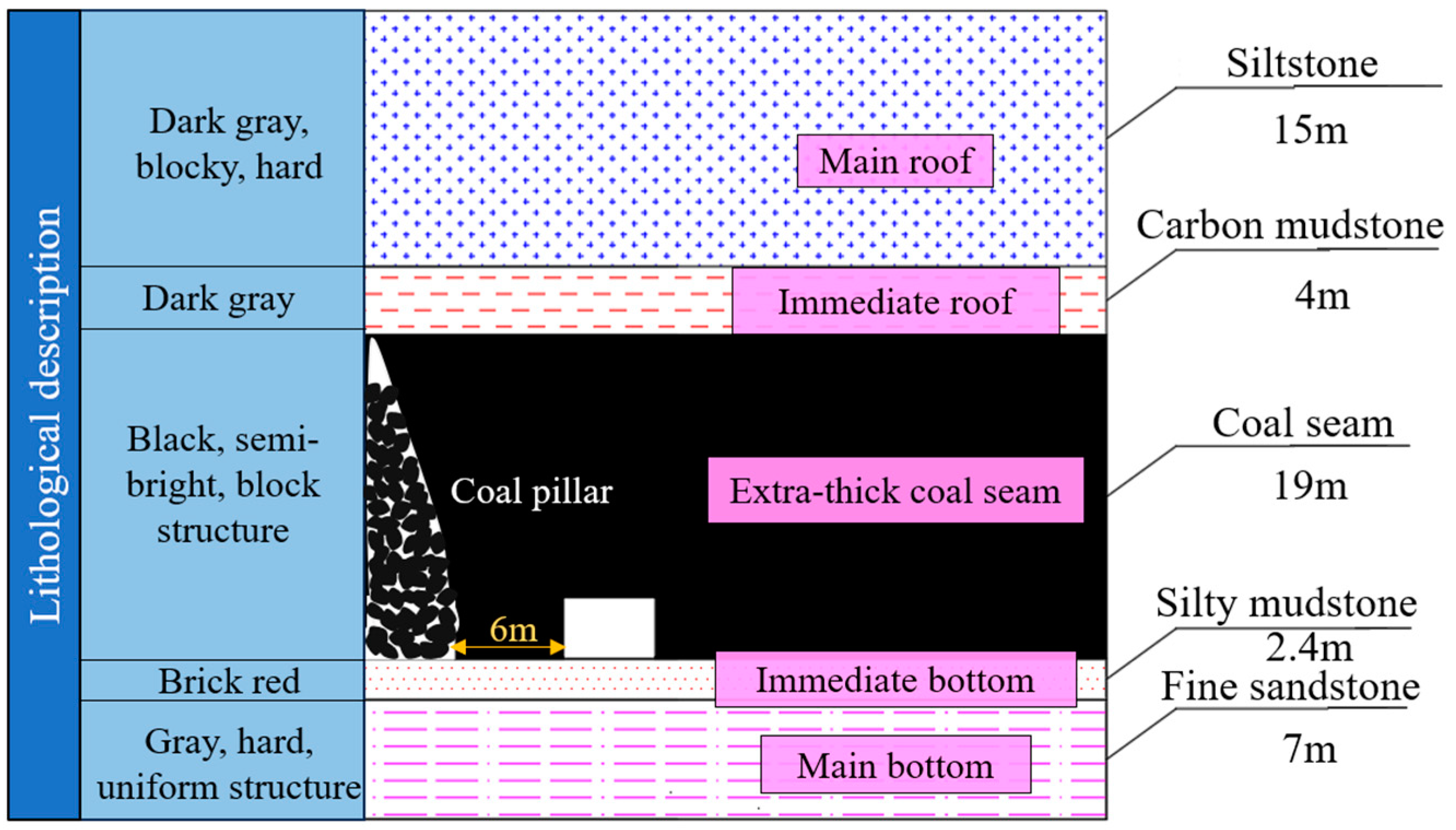
2. Engineering Background Profile

The 8310 working face of a mine adopts fully mechanized caving mining, and the 3 # coal seam is a near-horizontal coal seam, with an average burial depth of 560 m; the average thickness of coal seam is 19 m, and the width of narrow coal pillar is 6 m. The immediate roof is 4 m thick carbonaceous mudstone, the main roof is 15 m thick siltstone, the immediate bottom is 2.4 m thick silty mudstone, and the old bottom is 7 m thick fine sandstone. The schematic diagram of the coal seam roof and floor is shown in Figure 1.

3. Mechanical Model of Overburden Rock Structure

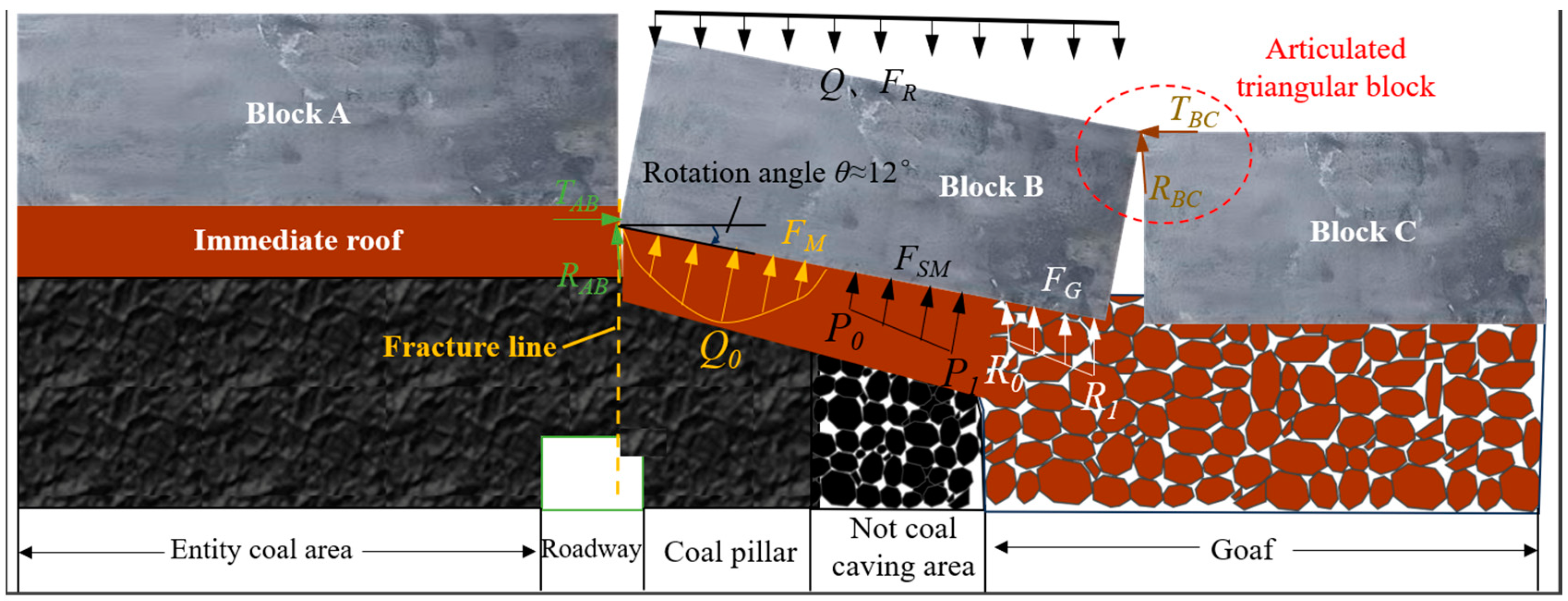
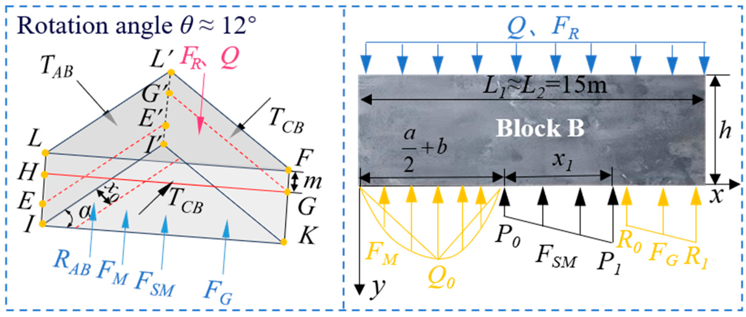
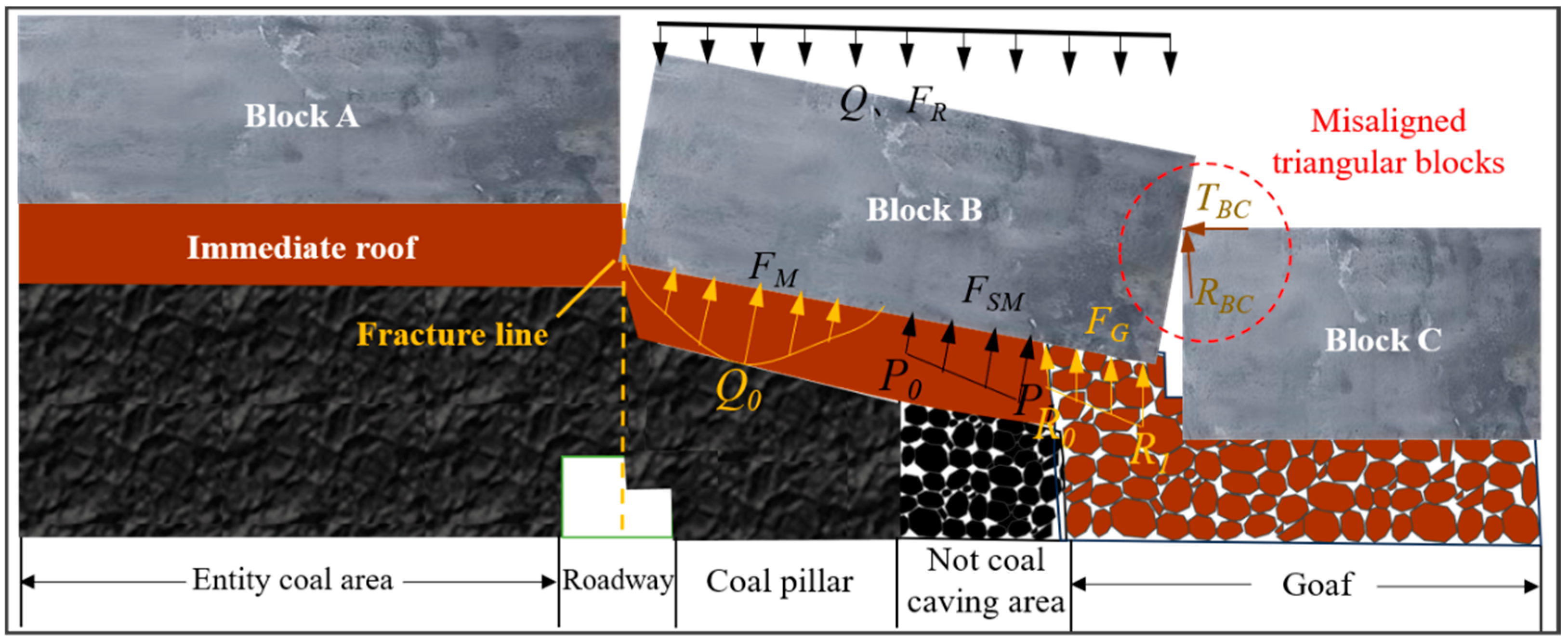
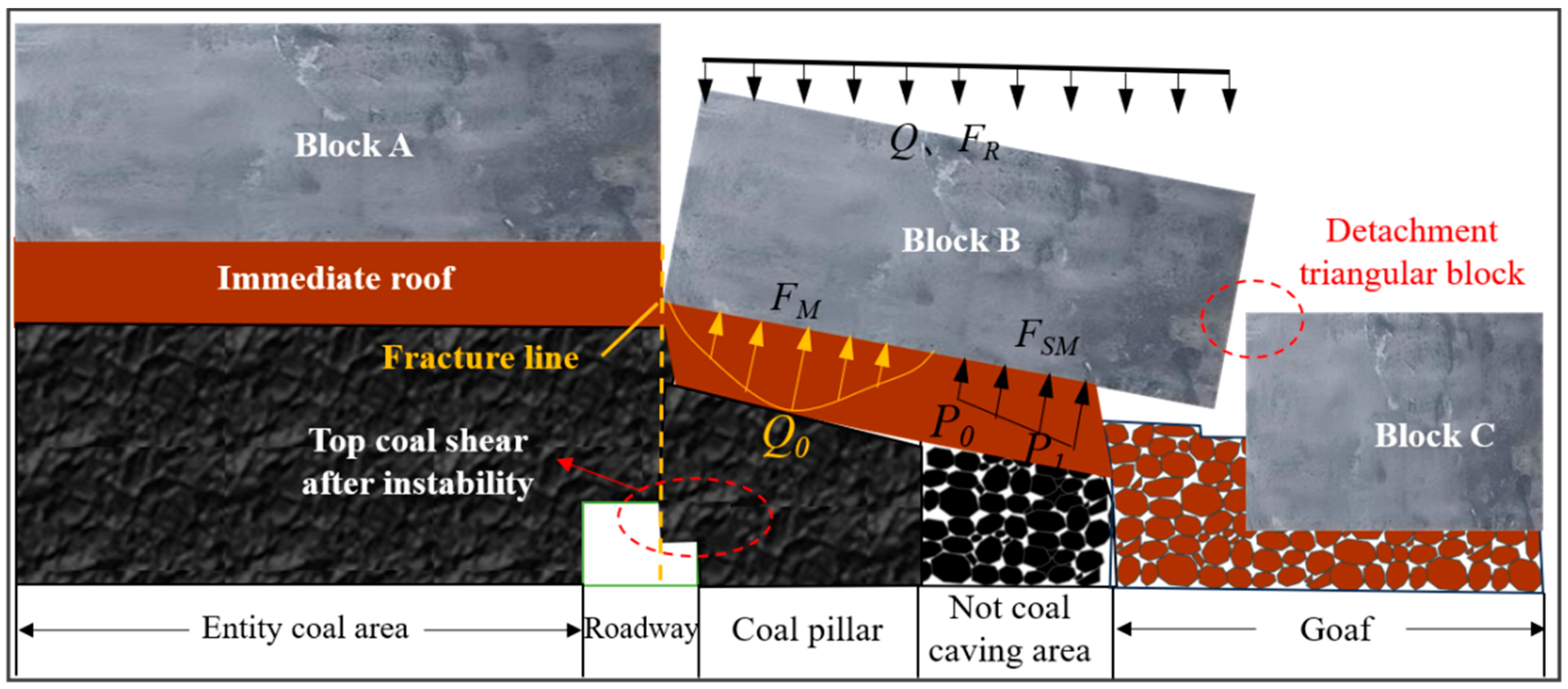
3.1. Key Triangular Block Structure of Gob-Side Entry

After the excavation of the working face, the main roof is broken in an arc shape at the end of the working face, forming a key triangular block structure. The articulated structure, formed by block A, key triangular block B (KTBB), and block C, is shown in Figure 2.
According to the contact relationship between KTBB and block C of the side triangular block, it can be divided into three forms: articulated triangular block, staggered triangular block, and detached triangular block. Q and FR represent the weight of key triangular block B and the overburden, respectively. The articulated triangular block is shown in Figure 3. Within the figure, RAB and TAB represent the resultant forces of the vertical shear force and the horizontal thrust, respectively, exerted by key rock block A on key rock block B. RBC and TBC represent the resultant forces of the vertical shear force and the horizontal thrust, respectively, exerted by block C on block B. FG is the supporting force exerted by the gob area gangue on the key rock block B. FSM is the support force of the uncoaled area to the main roof. FM is the supporting force provided by the coal pillar area on key rock block B. θ represents the rotation angle of the key block B.
In the stability analysis of traditional triangular blocks, combining the support forces from both the non-coal-released area at the end and the gangue area may result in less accurate data. When analyzing the articulated triangular block scenario, due to the substantial thickness of the coal seam, for KTTB and block C to achieve articulation, it is necessary for the fractured immediate roof to swell and fill the gob area as much as possible. Once stabilized in this manner, block C has the potential to establish articulated contact with KTTB.
When the articulated triangular block is present, a Cartesian coordinate system is established, with the hinge point connecting KTTB to block A serving as the origin. The positive x-axis is aligned with the direction of the gob area, while the positive y-axis points in the direction of the roadway. This allows for a stress analysis of the crucial triangular block, as illustrated in Figure 4.
The resultant force in the horizontal direction is zero.
T A B 2 T B C cos α = 0
where α represents the base angle of the KTTB.
The resultant force in the vertical direction is zero.
R A B 2 R B C + F M + F S M + F G F R Q = 0
where RAB is the resultant force of the vertical shear force applied by key rock block A to key rock block B, RBC is the resultant force of the vertical shear force applied by key rock block C to key rock block B, FG is the supporting force exerted by the gob area gangue on key rock block B, FSM is the support force of the uncoaled area to the main roof, FM is the supporting force provided by the coal pillar area on key rock block B, and Q represents the weight of key triangular block B.
Taking moments about the rotational axis EE′, the resultant moment is zero.
2 T B C m cos α + 0 a 2 + b f M 2 tan α x L 2 x f M d x + a 2 + b a 2 + b + x 1 f S M 2 tan α x L 2 x d x + a 2 + b + x 1 L 2 f G 2 tan α x L 2 x d x 2 R B C cos θ L 2 2 L 2 3 Q + F R cos θ = 0
where m represents the positional parameter of block A and block C relative to KTTB, L2 represents he lateral fracture span of key block B, and the variables a and b represent the widths of the roadway and the coal pillar, respectively, which are 5 m and 6 m.
m = 1 2 h L 2 sin θ = 5.94   m
where h represents the basic roof thickness.
The horizontal thrust TBC exerted by block C on KTTB is calculated as follows:
T B C = L 2 F R + Q 2 h L 2 sin θ 2 = 5.56 × 10 4   kN
Q = S Δ h Q γ Q
F R = S Δ h R γ R
where SΔ represents the area of KTTB, hQ and γQ represent the thickness and volumetric force of KTTB, and hR and γR represent the thickness and the volumetric force of the overlying weak rock layer.
The following calculation is performed:
Q + F R = 9.97 × 10 4   kN
TAB is obtained:
T A B = L 2 F R + Q cos α h L 2 sin θ 2 = 7.87 × 10 4   kN
An analysis of the lateral supporting force per unit area, fM, for a parabolic-shaped coal body yielded the following results:
f M x = x 2 a 2 + b x + Q 0 a 2 32 a b 8 b 2 8
F M = 0 a 2 + b f M 2 tan θ x L 2 d x
The supporting force per unit area, fSM, exerted on KTTB by the unmined area is given by:
f S M x = P 1 P 0 x 1 x a 2 b + P 0
F S M = a 2 + b a 2 + b + x 1 f S M 2 tan θ x L 2 d x
The supporting force per unit area, fG, exerted on KTTB by the gangue in the gob area is given by:
f G x = R 1 R 0 L 2 a 2 b x 1 x a 2 b x 1 + R 0
F G = a 2 + b + x 1 L 2 f G 2 tan θ x L 2 d x
Then, (5)–(7), (11), (13), and (15) are substituted into (3):
R B C = 1 L 2 cos θ 2 T B C m cos α + 0 a 2 + b f M 2 tan α x L 2 x d x + a 2 + b a 2 + b + x 1 f S M 2 tan α x L 2 x d x + a 2 + b + x 1 L 2 f G 2 tan α x L 2 x d x L 2 3 Q + F R cos θ
R B C = 1.25 × 10 6   kN
R A B = 4.34 × 10 5   kN
As calculated from the above equation:
R A B T A B t a n φ
where φ represents the angle of internal friction.
The shear force between block A and KTTB exceeds the friction force caused by their horizontal thrust, causing key block B to slide. The sliding instability of KTTB seriously affects the safe production of the coal mine. Therefore, high-strength anchor cable support must be implemented directly below the shear zone.
The specific configuration of the misaligned triangular block structure is illustrated in Figure 5. After coal mining operations, block C loses support and falls, eventually stabilizing on the gangue pile within the gob area. At this point, a unique misaligned state emerges between KTTB and block C. It is worth noting that in this condition, block A no longer exerts a vertical shear force or horizontal thrust on KTTB. Consequently, KTTB, devoid of these external forces, begins to undergo rotational deformation and gradually loses stability. Due to the incomplete filling of the gob area with gangue, block C is positioned just right to form an effective overlap with KTTB after its rotational instability.
In contrast, the characteristics of the detached triangular block structure are illustrated in Figure 6. In situations where the coal seam is thick and the swelling coefficient is small, when the gob area stabilizes and block C reaches a stable state, the rotationally unstable KTTB fails to successfully engage with block C. Over time, these two blocks ultimately exhibit a state of mutual detachment.

3.2. Top Coal Subsidence Model and Numerical Simulation

With the mining of coal seams, if the main roof fractures directly above the roadway, it exerts pressure on the top coal, inducing shear failure. A top coal subsidence model was developed and analyzed using the UDEC 7.0 numerical simulation software. This study revealed the shear failure characteristics of the coal mass above the roadway and the stress evolution patterns.

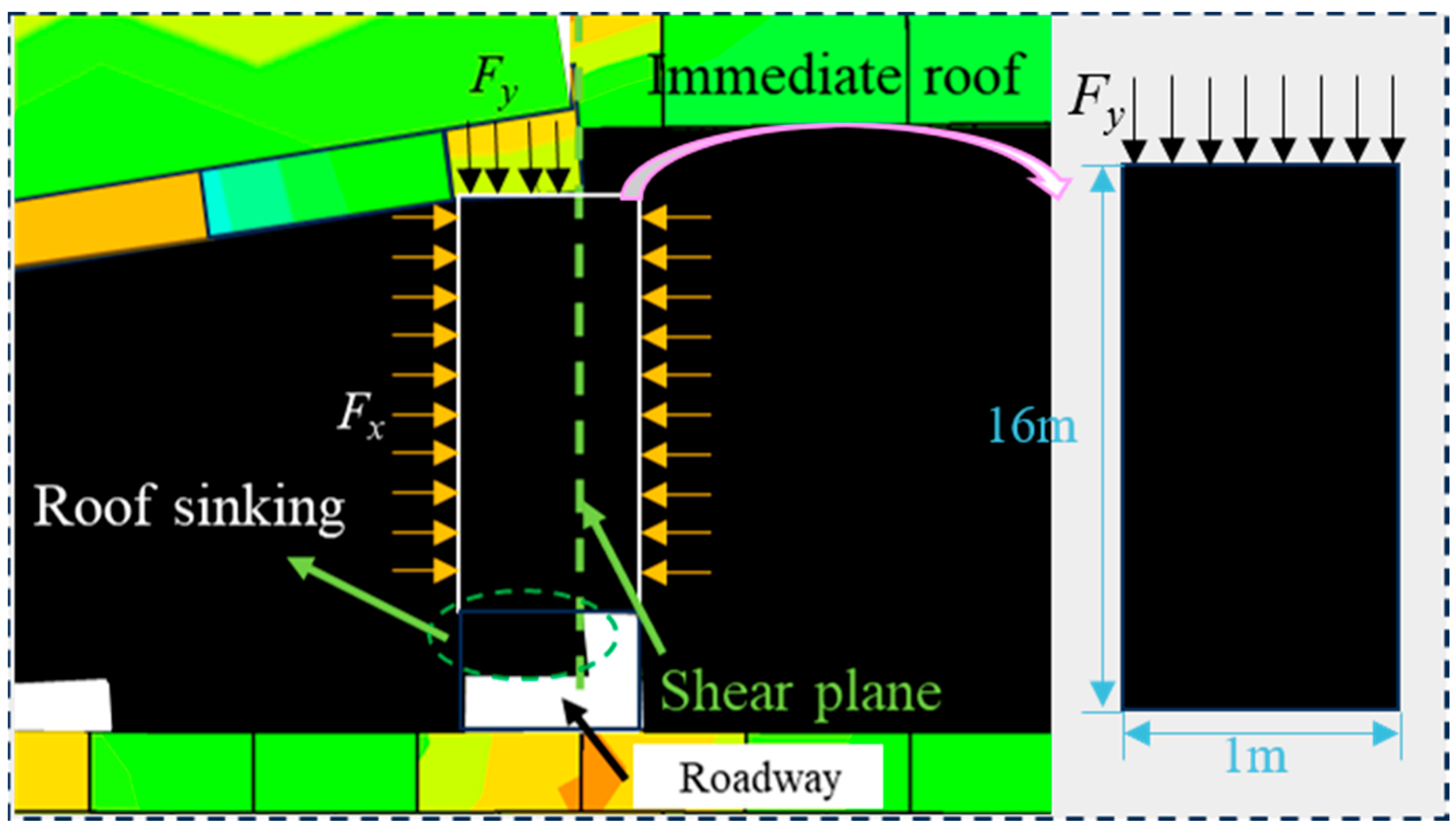
3.2.1. Top Coal Subsidence Model

The pressure exerted by the overlying main roof on the underlying coal body can be categorized into horizontal pressure and vertical pressure, and the influence differs based on the distinct locations of the MRFL above the roadway. When the fracture line is 1.5 m away from the coal pillar side, the top coal is almost equally affected by both the overhead horizontal and vertical pressures. When it is 2.5 m away, the top coal is primarily influenced by vertical pressure, with horizontal pressure having a lesser impact compared to vertical pressure, as shown in Figure 7.
The stress analysis of the shear structure model of the top coal is carried out to explain the cause of the shear subsidence of the top coal, as shown in Figure 8.
The shear strength τ of the rock has the following relationship with compressive stress σ:
τ = C + σ t a n φ
where tanφ represents the internal friction coefficient of rock shear and C represents the cohesive force of the rock. The data (φ = 24.5°; C = 5.42 MPa) are derived from the triaxial compression test of rock samples in the study area.
Equation (20) yields:
τ = 5.96 MPa
The top coal can withstand the maximum shear force T:
T = τ A
T = 9.53 × 10⁴ kN < 9.97 × 10⁴ kN
The above calculation process is under the condition of unit width. Because the shear force Fy is greater than the maximum shear force T that the top coal can bear, the shear failure of the top coal occurs.

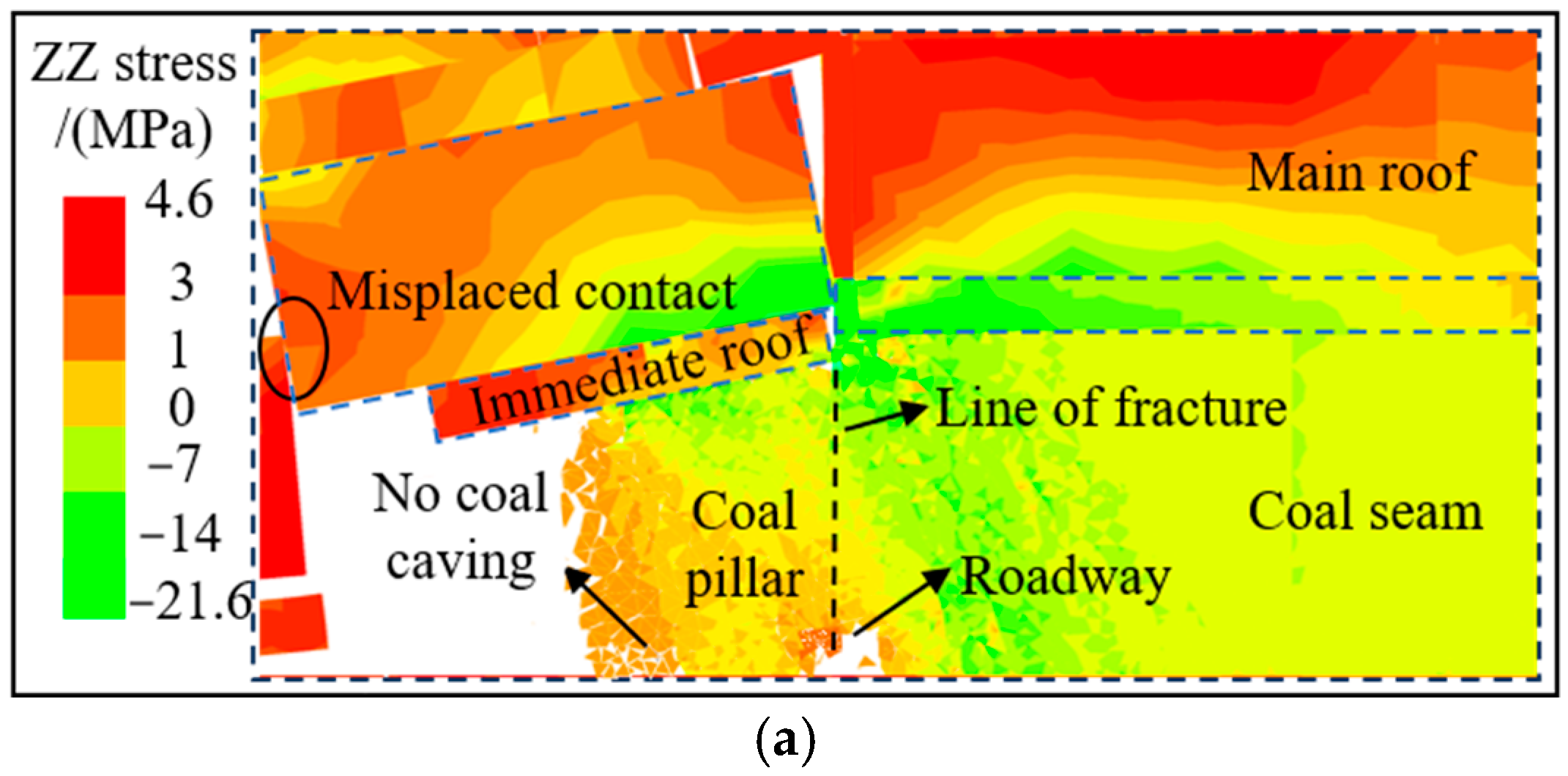
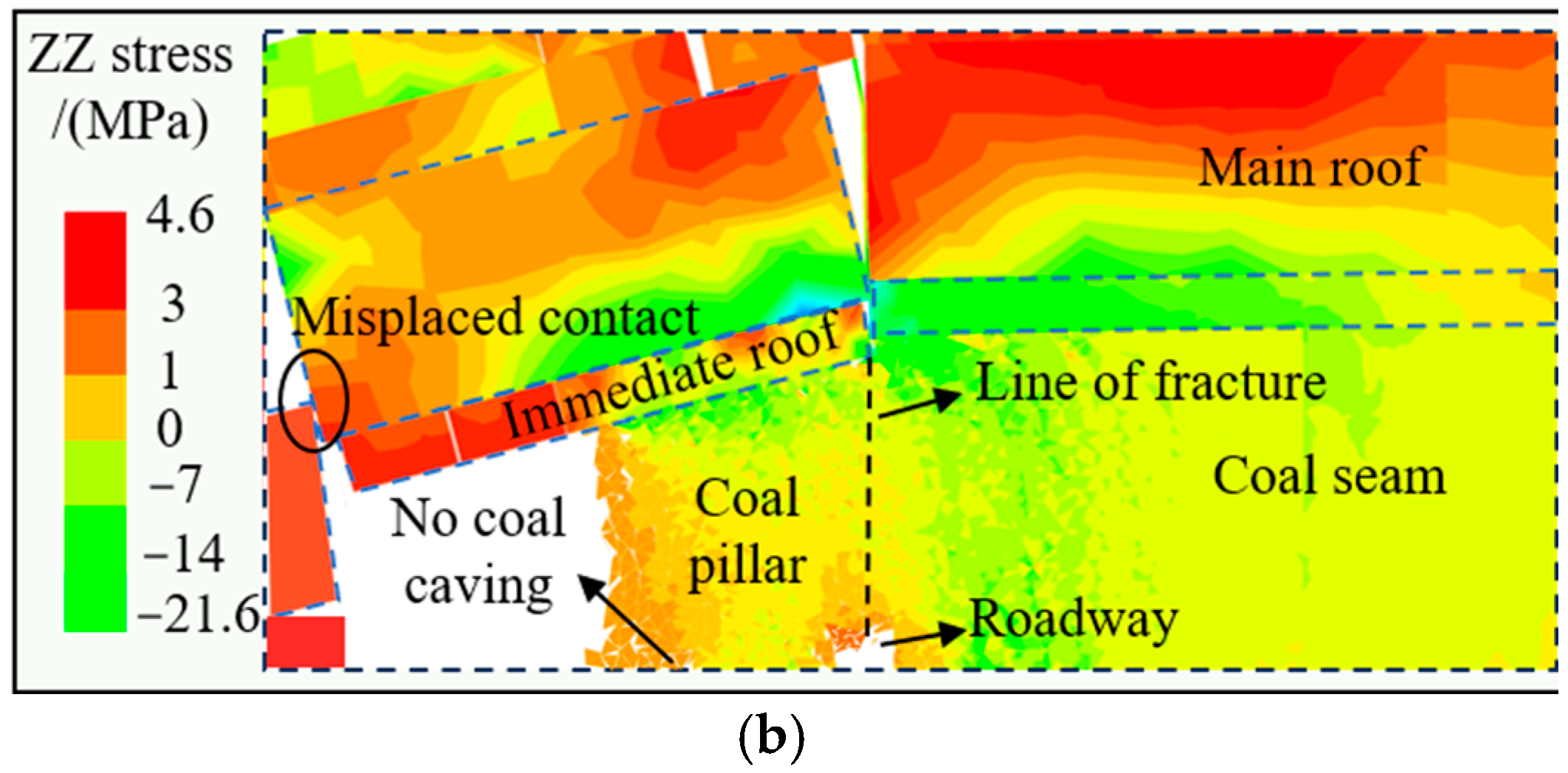
3.2.2. Numerical Simulation

Based on the actual geological conditions of the 8310 working face and the mechanical parameters of coal–rock strata (Table 1), this study established a numerical analysis model measuring 180 m × 53 m (length × width) using UDEC 7.0 software (see Figure 9), aiming to simulate the stress evolution law and overburden structure characteristics under different fracture positions of the main roof. The left, right, and lower boundaries of the model limit the speed and displacement. The upper boundary applies a 12.0 Pa uniform load and increases according to the buried depth gradient. The lateral pressure coefficient is set to 1.2.
As the coal mining face progresses, the rock strata above lose their support from the coal seam, resulting in phenomena such as cracking, tilting, and settlement. This process results in the significant deformation of the roof, forming a drastic deformation zone. Since the MRFL sits directly over the roadway, any shifts in its position directly affect the stability of the roadway’s ceiling. Through simulations and actual measurements, we observed that block B fractures along the MRFL, causing a certain degree of compression on the underlying coal body, and stress concentration develops in the roadway roof, resulting in the localized failure of the roof structure, as shown in Figure 10.
Figure 11 displays the vertical stress distribution in the roadway’s surrounding rock, derived from UDEC7.0 numerical simulations, for various distances between the MRFL and the coal pillar side. The conclusions are as follows:
(1)
The numerical results demonstrate that the roadway roof experiences tensile stresses of approximately 2 MPa under both operational conditions, significantly exceeding the tensile strength 0.5 MPa for coal seams. This substantial stress–strength imbalance indicates a high risk of roof failure.
(2)
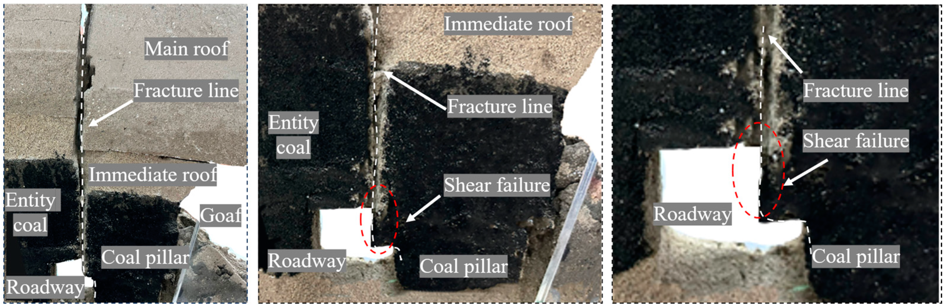
The compressive stress value at the junction of the coal seam and the immediate roof fluctuates in the range of 2 to 5 MPa. Notably, shear failure has already taken place within the coal mass at this location and the shear position is located directly below the fracture line.
(3)
When the MRFL is arranged at 1.5 m from the side of the coal pillar, the solid coal side of the roadway is closer to the vertical stress peak area. In contrast, when the distance is 2.5 m, the vertical stress peak covers a wider range on the solid coal side. The vertical stress peak of the former is 19.5 MPa, and the vertical stress peak of the latter is 21.6 MPa.

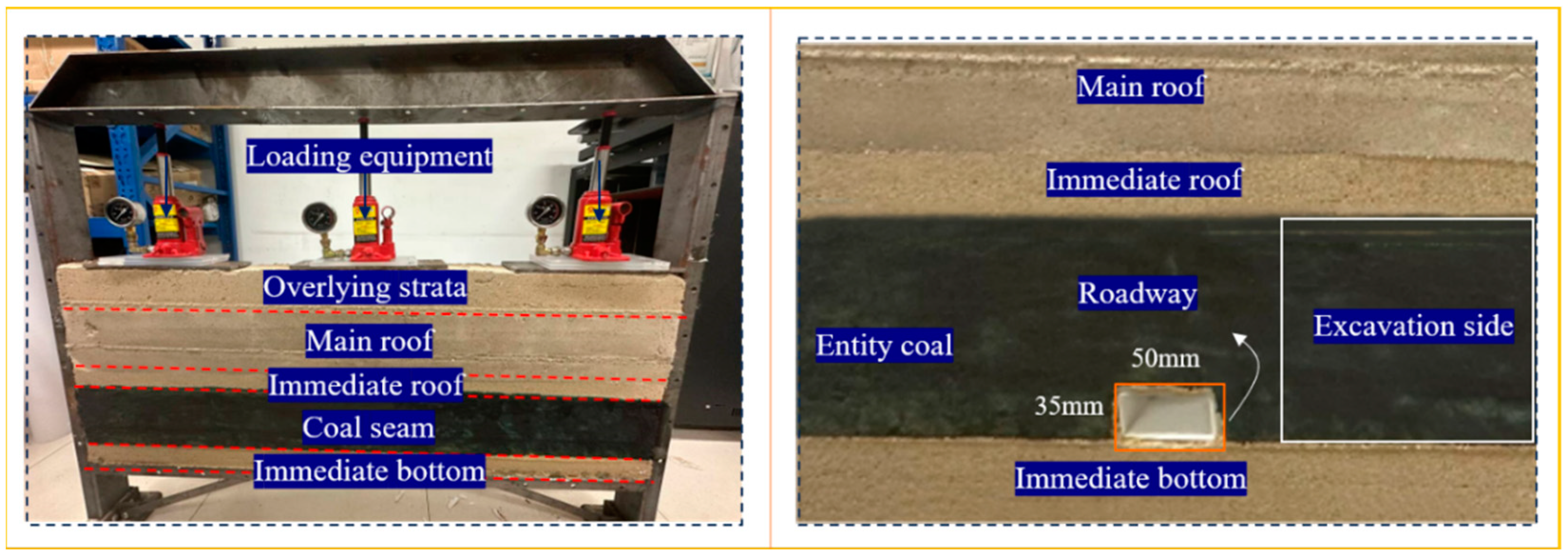
4. Similarity Simulation Experiments

4.1. Similarity Simulation Material Ratio

To conduct a thorough examination of the influence of the MRFL located above the roadway on the surrounding rock damage in exceptionally thick coal seams, physical similarity simulation experiments were undertaken.
The model’s geometric similarity ratio stands at 100:1. The simulation process is similar to the actual excavation process on site, requiring similar load ratios, boundary conditions, and time scales. The excavation conditions were similarly configured to involve the gradual excavation of both the roadway and the adjacent coal body on the right, while observations focused on assessing the fracture state of the main roof located above the roadway. Based on the similarity material proportioning table, the materials and proportions for each rock stratum in the similarity model are determined and presented in Table 2.

4.2. Simulation Experiment Process

The model was horizontally layered, with mechanical parameters for each layer calculated using a similarity ratio based on experimental workface data. Proportioning tests with aggregate (fine river sand), cementing materials (gypsum and lime), and layering material (mica powder) determined the experimental proportions. The material volumes were then determined and laid out according to layer thickness, geometric similarity, and test bench size. The constant external force is used to simulate the self-weight of overlying strata caused by the buried depth of coal seam. After air-drying and ensuring layer strength, excavation tests were performed. The final laid-out and dried model is depicted in Figure 12.
This model is designed to investigate the deformation characteristics of roadway surrounding rock and overlying coal strata during main roof fracturing in the mining process. During coal seam extraction, the immediate roof collapses progressively with mining advancement, while stress concentration effects gradually develop in the roadway roof. When the fractured main roof blocks rotate to a critical angle, they ultimately induce shear failure in the coal seam along the fracture line. Notably, the position of the fracture line (1.5 m or 2.5 m from the coal pillar side) not only controls the propagation range of shear failure in the overlying coal seam but also determines the severity of roadway damage, demonstrating significant spatial correlation between these factors. Figure 13 and Figure 14 clearly illustrate the localized instability occurring in the roof structure.
The deformation characteristics of overlying coal strata during main roof fracturing, as obtained from the physical similarity simulation experiments, demonstrate remarkable consistency with the numerical simulation results. These findings conclusively demonstrate that the combined effects of coal seam extraction and MRFL development exert substantial influence on roadway stability. To address these challenges, the implementation of high-strength bolt-cable support systems becomes imperative. Specifically, this study proposes an innovative support scheme utilizing a novel five-hole large bearing plate integrated with bolt-cable systems, which has been specifically designed to counteract the destabilizing effects observed in both experimental and numerical analyses.

5. Control of Fracture of Main Roof Directly Above Roadway

5.1. The Important Role of Anchor (Cable) Prestress

Currently, bolt (cable) support technology is the primary means of underground roadway support in coal mines in China [30,31], and its significance cannot be overstated. The core function of bolt support lies in significantly enhancing the strength of the surrounding rock. For structural weaknesses within the surrounding rock, such as joints and fractures, bolts can tightly connect them into a cohesive whole, effectively preventing interlayer or joint displacement and sliding by bolstering the overall shear strength of the surrounding rock, thus maintaining stability. Furthermore, by providing axial and tangential forces, bolts can eliminate tensile stresses in the surrounding rock, keeping it in a state of overall compression. In shear zones, the compressive stress provided by bolts also increases friction, further enhancing the shear resistance of the surrounding rock. The prestressed bolt (cable) combined support technology creates a functional compressive stress-bearing framework within the surrounding rock, facilitating proactive reinforcement and thereby enhancing the control over deformation and failure of the rock mass.

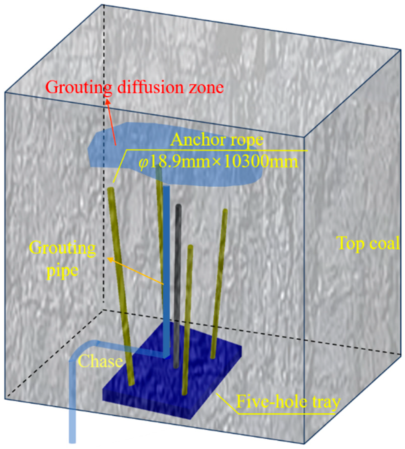
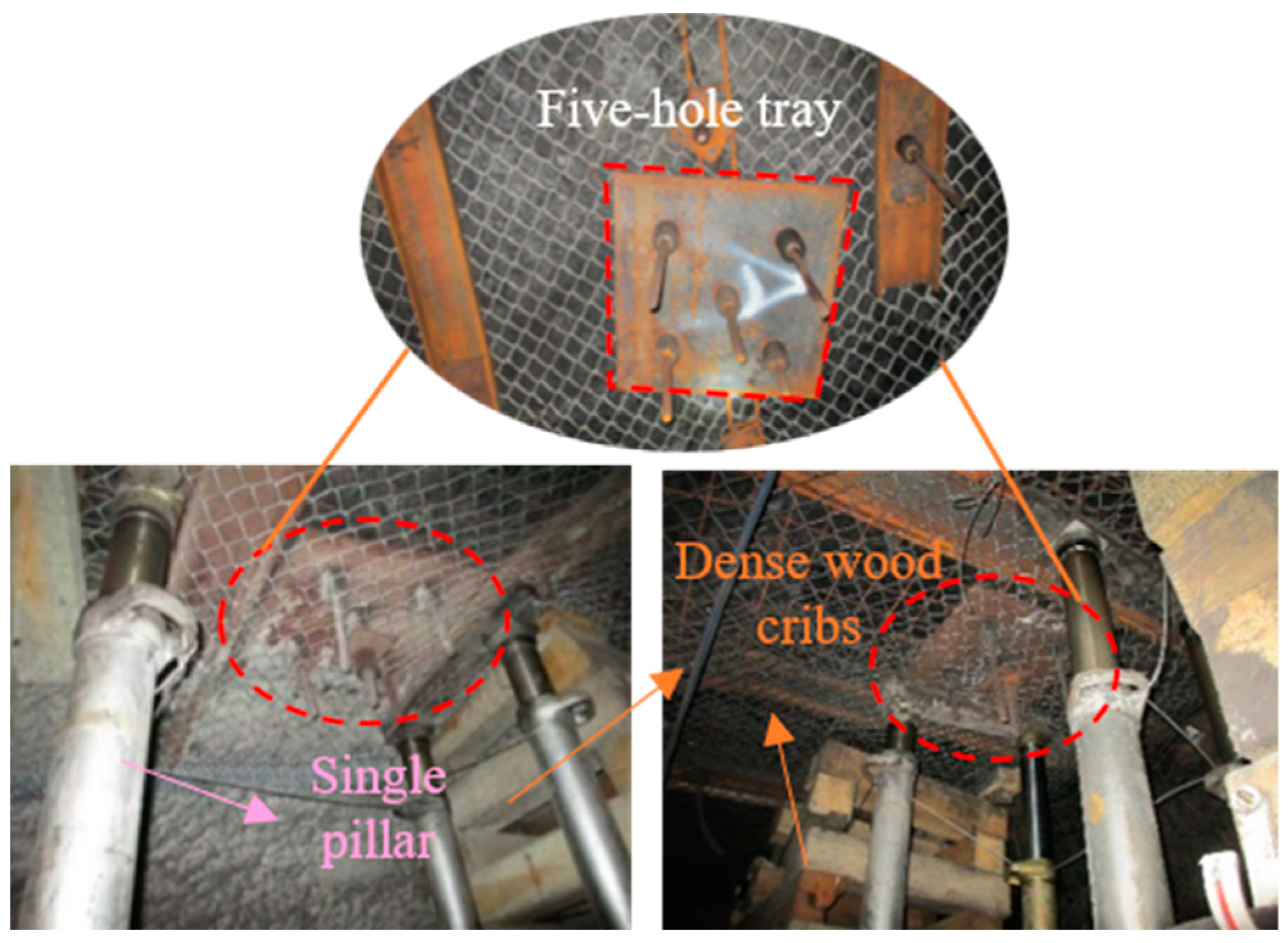
5.2. Five-Hole Tray and Prestressed Field of High-Strength Prestressed Anchor Cable

To prevent roof subsidence caused by the shearing-off of the main roof along fracture lines, which could lead to roadway damage, we have employed a specialized reinforcement and anchoring support system utilizing five-hole trays in conjunction with anchor cables, positioned directly beneath the MRFL. Based on the basic principle of bolt (cable) prestress application, the numerical model of prestress field analysis was established by using FLAC3D 7.0. Using this approach, we can better understand the support structure’s mechanics and refine the design to guarantee roadway safety and stability.

5.2.1. Five-Hole Tray and High-Strength Anchor Cable Support System

The five anchor cables on the five-hole tray were arranged in a ‘five-petal’ layout. The middle anchor cable was perpendicular to the roof, and the surrounding four anchor cables had a certain angle. The dimensions of the five-hole tray were 600 × 600 × 16 mm. The pull force of the anchor was 180 kN. The material of the tray was Q345B low-alloy steel. The secondary effect of over-reinforcement has a potential threat to the stability of the roadway. It is recommended to adopt a progressive reinforcement strategy of ‘stiffness adaptation’ to avoid secondary disasters caused by local over-reinforcement. A chase was excavated on the side of the five-hole tray, within which a grouting pipe was arranged. The position of the grout outlet was roughly slightly higher than the middle anchor cable in the five-hole tray, a cement-based composite slurry (water–cement ratio 0.7) was used, and the grouting pressure was 0.5 MPa, as shown in Figure 15 and Figure 16.
By arranging a five-hole tray equipped with high-strength prestressed anchor cables directly beneath the fracture line, two levels of shear resistance were achieved. Primary shear resistance was enhanced due to the constraint provided by the large tray positioned below. Secondary shear resistance was further augmented through the increase in horizontal compressive force on the top coal, stabilizing the top coal via this dual-level shear resistance mechanism, as shown in Figure 17.

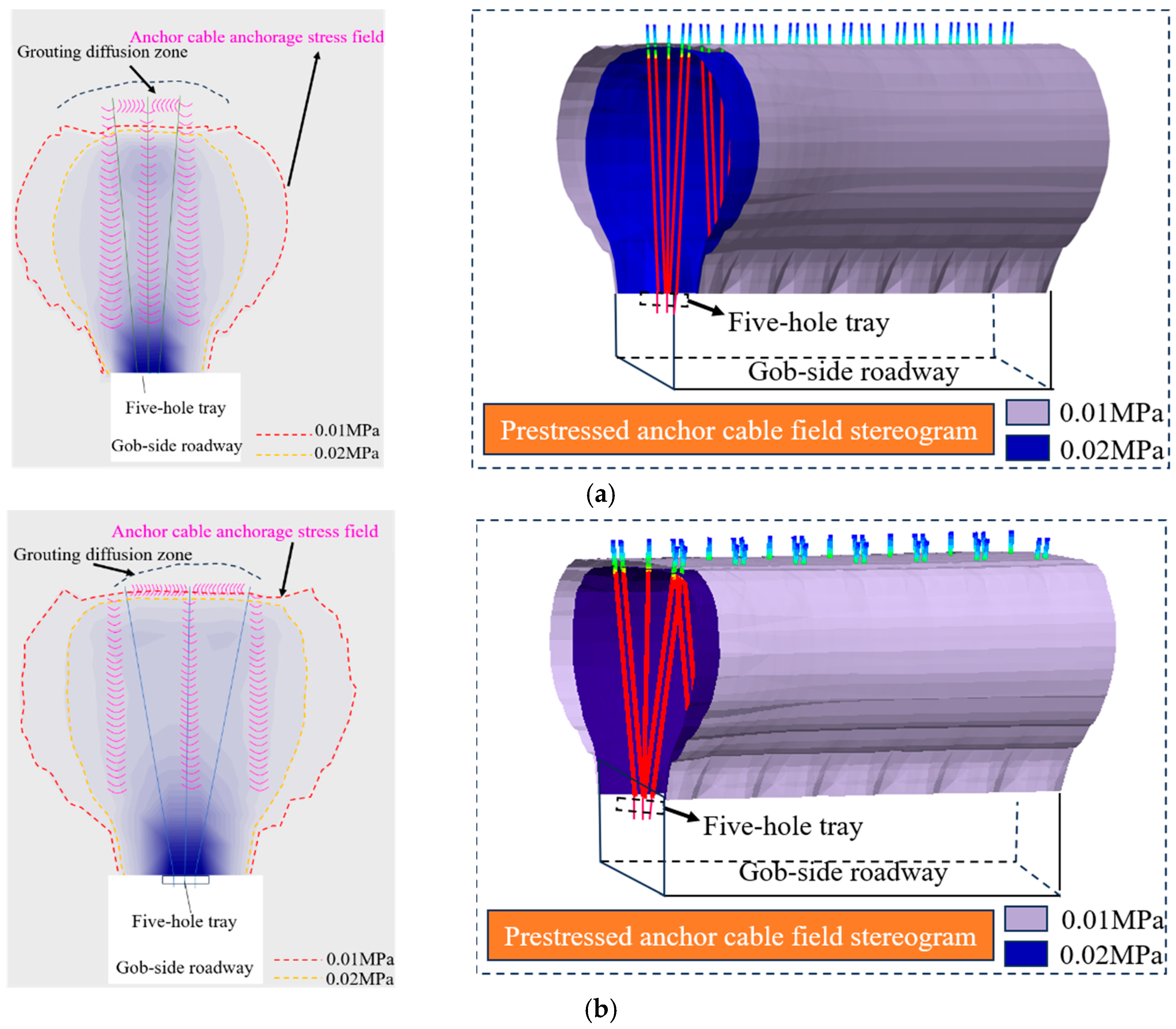
5.2.2. Prestress Field Analysis of Five-Hole Tray and High-Strength Anchor Cable

FLAC3D 7.0 software was employed to examine the distribution patterns of the stress field caused by the anchor cables, disregarding the initial in situ stress conditions. The Young’s modulus of the anchor cables was 2 × 10¹⁰ Pa, the tensile strength was 3.1 × 10⁵ N, and the cross-sectional area was 0.0003572 square meters. The prestress field of the anchor cables with the five-hole tray is shown in Figure 18 below (including two cases where the anchor cables on both sides are deflected by 5° and 10°).
(1)
As the roof moved deeper away from the tail of the anchor cable, the compressive stress gradually diminished. A tensile stress zone emerged at the anchor cable’s end, albeit with a relatively modest stress value.
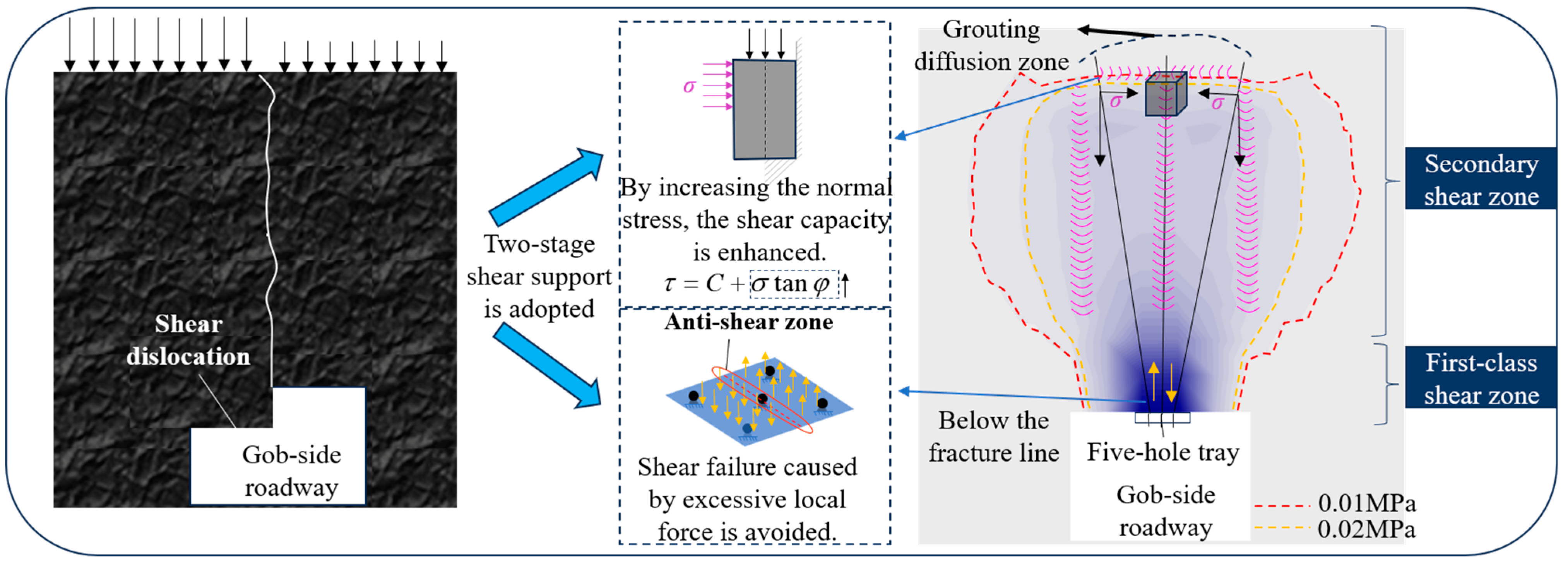
(2)
As the deflection angle of the anchor cables on both sides increased from 5° to 10°, the area of the effective compressive stress zone expanded significantly, forming a contiguous and overlapping effective compressive stress zone that nearly covered the entire roof area. Under both conditions, the coverage range of 0.01 MPa stress was significantly larger than that of 0.02 MPa. When comparing different angles, the stress coverage range at a deflection angle of 10° was markedly greater than that at 5°.
(3)
Grouting pipes were arranged through concealed chase for grouting reinforcement, with the diffusion range essentially covering the entire upper part of the anchored cable bundle.

6. Engineering Application Analysis

A combined control means of strong bolt (cable) support and (roof) five-hole tray and high-strength prestressed anchor cable support in the roadway (roof and two sides) was formed, as shown in Figure 19.

6.1. Roadway Roof Support

All bolts were φ22 × 2400 mm, with an interval of 800 × 800 mm and six bolts in each row. The roof anchor cable was 18.9 × 8300 mm high-strength prestressed anchor cable, with an interval of 800 × 1800 mm, and five anchor cables in each row.
The bundle anchor cable comprises five high-strength prestressed cables and five-hole trays, arranged in a specific ‘2-1-2’ configuration, as shown in Figure 20. The tray spacing was 2400 mm. Each cable was φ18.9 mm × 10,300 mm, with diagonally arranged peripheral cables. The tray was a 600 × 600 × 16 mm steel plate. The bundle anchor cables were positioned directly beneath the main roof’s fracture line.
The roadway support adopts a dense wood crib and single-pillar support, as shown in Figure 21. The dense wood crib plays a buffer role in support. At the same time, through dense arrangement, wood cribbing plus a single pillar can form a stable support system. It effectively withstands the deformation and pressure exerted by the surrounding rock, ensuring the continued stability of the roadway.

6.2. Support for Coal Pillar Sidewall

There were five bolts in each row of the coal pillar side and the angle between the two bolts near the floor and the roof and the horizontal angle was 10°. At the upper and lower corners of the coal pillar side, anchor cables of φ18.9 × 4300 mm were arranged 550 mm away from the roof and the floor, respectively, with a spacing of 1800 mm between each anchor cable. Additionally, an anchor cable of φ18.9 mm in diameter and 4300 mm in length was placed 1650 mm away from the upper corner, as shown in Figure 19 and Figure 20. Each of these three types of anchor cables utilized a high-strength W-shaped steel strip along the horizontal direction.

6.3. Support for Solid Coal Sidewall

Each row of the solid coal side was equipped with four bolts, with the topmost and bottommost bolts positioned 150 mm away from the roof and the floor, respectively. The lower two bolts and the upper two bolts were symmetrical, and the parameters were the same. The side also employed φ18.9 × 5300 mm anchor cables, one per row, positioned at the center of the coal pillar side. These anchor cables were located 1750 mm from the roof, with a row spacing of 1800 mm, as shown in Figure 19 and Figure 20.

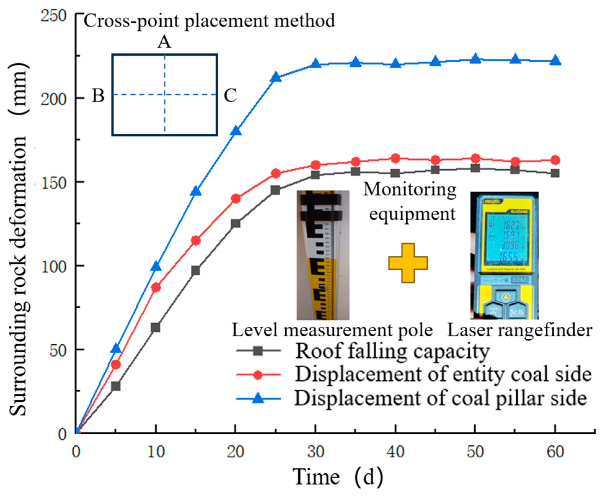
6.4. Observation Results of Mine Pressure

In the process of excavation and mining, adopts the cross-point method to monitor the deformation of the roadway’s surrounding rock, and the monitoring equipment is a tower ruler and a laser range finder. The measurement frequency is once every five days. The core features of the cross-point method are simple structure and intuitive data.
The results obtained during the roadway excavation are presented in Figure 22. These results indicate that the deformation stabilized approximately 30 days after excavation, with a maximum roof subsidence of 159 mm. In addition, maximum convergence values of 219 mm and 160 mm were recorded for the pillar side and solid coal side, respectively. After mining the coal seam, the maximum subsidence of the roadway roof was recorded at 235 mm, with maximum convergence values of 306 mm and 281 mm observed on the coal pillar side and solid coal side, respectively. Notably, during the entire retreat mining period, there were no instances of severe mining pressure phenomena such as monolithic pillar compression or anchor cable failure in the roadway.
The aforementioned data and observations indicate that, in the context of an extra-thick coal seam where the MRFL is positioned above the gob-side roadway, utilizing a five-hole tray in conjunction with high-strength prestressed anchor cables for support yields notable outcomes in managing roof deformation.

7. Conclusions

(1)
Three structural models of the overlying rock were proposed when the MRFL is located above the gob-side entry. These models were classified as articulated, misaligned, and detached. Furthermore, a mechanical model was developed to simulate the shear subsidence of the top coal. By integrating this model with UDEC numerical simulations, we elucidated the mechanism of shear failure in the top coal when the MRFL is positioned above the roadway. The numerical results demonstrate that the roadway roof experienced tensile stresses of approximately 2 MPa, significantly exceeding the tensile strength 0.5 MPa for coal seams. The failure characteristics of the surrounding rock in the roadway obtained through similarity simulation experiments were generally consistent with those in the numerical simulation.
(2)
The prestress field of a five-hole tray combined with high-strength prestressed anchor cables was obtained by FLAC3D numerical simulation. It could be clearly seen that a continuous overlapping effective compressive stress zone covering the entire roof was formed between the anchor cables, which gave full play to the active support of the anchor cables. The coverage range of 0.01 MPa stress was significantly larger than that of 0.02 MPa. When comparing different angles, the stress coverage range at a deflection angle of 10° was markedly greater than that at 5°.
(3)
After adopting the five-hole tray support system integrated with high-strength prestressed anchor cables, the deformations of the roof and both coal walls were effectively controlled within a limited range. The monitoring data indicated that the deformation stabilized approximately 30 days post-excavation, with a maximum roof subsidence of 159 mm. Additionally, maximum convergence values of 219 mm and 160 mm were recorded on the pillar side and solid coal side, respectively. These findings provide robust theoretical and technical support for roadway stabilization under similar geoengineering contexts.

Author Contributions

Conceptualization, D.C.; methodology, J.C., J.Z. and C.T.; software, J.C., F.G., X.Y. and Z.Z.; formal analysis, J.C. and J.N.; investigation, D.C.; resources, D.C.; data curation, S.X. (Shengrong Xie), J.Z., S.X. (Shikun Xing) and W.Z.; writing—original draft preparation, J.C.; writing—review and editing, D.C.; visualization, J.C.; supervision, D.C.; project administration, J.C.; funding acquisition, D.C. All authors have read and agreed to the published version of the manuscript.

Funding

This research was supported with funding awarded from the National Natural Science Foundation of China (Grant Nos. 52374149, 52004286), the China Postdoctoral Science Foundation (Grant No. 2020T130701), and the Fundamental Research Funds for the Central Universities (Grant No. 2022XJNY02).

Institutional Review Board Statement

Not applicable.

Informed Consent Statement

Not applicable.

Data Availability Statement

The original contributions presented in the study are included in the article, and further inquiries can be directed to the corresponding author.

Acknowledgments

Heartfelt thanks to the following enterprises in the research process to provide support and assistance: Anhui Hengyuan Coal and Electricity Co., Ltd. for this study provides valuable on-site data and technical guidance; Jizhong Energy Co., Ltd. provides professional facilities and collaboration conditions for experimental analysis and results verification.

Conflicts of Interest

Authors Jun Zou and Jie Ni ware employed by the company Anhui Hengyuan Coal & Electric Co., Ltd.; author Chunyang Tian was employed by the company Songxinzhuang Coal Mine; and author Shikun Xing was employed by the company Jizhong Energy Co., Ltd. The remaining authors declare that the research was conducted in the absence of any commercial or financial relationships that could be construed as a potential conflict of interest.

Abbreviations

The following abbreviations are used in this manuscript:
MRFLMain roof fracture line
KTBBKey triangular block B

References

  1. Xu, S.S.; Peng, S.P.; Cheng, A. Coal Scientific Production Capacity and Resource Guarantee Level Analyses in China. Coal Geol. China 2011, 23, 1–4. [Google Scholar]
  2. Wang, J.C.; Zhong, S. The present status and the key issues to be resolved of thick seam mining technique in China. Sci. Online 2008, 11, 829–834. [Google Scholar]
  3. Hu, S.R.; Lin, L.N.; Huang, C.; Chen, D.Y.; Hao, G.Q. Distribution and Genetic Model of Extra-thick Coal Seams. Coal Geol. China 2011, 23, 1–5. [Google Scholar]
  4. Wang, G.F.; Pang, Y.H. Fully mechanized coal mining and caving mining method evaluation and key technology for thick coal seam. J. China Coal Soc. 2018, 43, 33–42. [Google Scholar]
  5. Song, X.; Zhu, D.; Wang, Z.; Huo, Y.; Liu, Y.; Liu, G.; Cao, J.; Li, H. Advances on Longwall Fully-mechanized Top-coal Caving Mining technology in China During Past 40 years: Theory, equipment and approach. Coal Sci. Technol. 2021, 49, 1–29. [Google Scholar]
  6. Wang, J.; Yu, B.; Kang, H.; Wang, G.; Mao, D.; Liang, Y.; Jiang, P. Key technology for fully-mechanized top coal caving with large mining height in extra-thick coal seam. J. China Coal Soc. 2013, 38, 2089–2098. [Google Scholar]
  7. Chen, D.; Zhu, J.; Ye, Q.; Ma, X.; Xie, S.; Guo, W.; Li, Z.; Wang, Z.; Feng, S.; Yan, X. Application of Gob-Side Entry Driving in Fully Mechanized Caving Mining: A Review of Theory and Technology. Energies 2023, 16, 2691. [Google Scholar] [CrossRef]
  8. Qian, M.G.; Miao, X.; He, F. Key block analysis of ‘masonry beam’ structure in stope. J. China Coal Soc. 1994, 19, 557–563. [Google Scholar]
  9. Hou, C.J.; Li, X.H. Stability principle of large and small structure of surrounding rock in gob-side entry driving with fully-mechanized caving. J. China Coal Soc. 2001, 26, 1–7. [Google Scholar]
  10. Zha, W.-H.; Li, X.; Hua, X.-Z.; Wu, T.-F.; Yin, S.-Y. Impact and application on narrow coal pillar for roadway protecting from fracture position of upper roof. J. China Coal Soc. 2014, 39, 332–338. [Google Scholar]
  11. Liu, J.; Li, C.; Shi, Y.; Zhang, Y. Stability Analysis and Fracture Patterns of Hard Main Roof in Longwall Top Coal Caving with Large Mining Height. Shock. Vib. 2021, 2021, 9930221. [Google Scholar] [CrossRef]
  12. Li, H.-B.; Li, D.-Y.; Wang, H.; Li, Z.-F.; Wang, S.; Chen, C.-L. Research on Stress Evolution Law and Failure Characteristics of Top Coal in Fully Mechanized Caving of Extra-Thick Coal Seams. Therm. Sci. 2014, 27, 687–695. [Google Scholar] [CrossRef]
  13. Yue, S.; Xie, S.; Chen, D.; Gao, M. Study on Surrounding Rock Control of Narrow Coal Pillar in Fully Mechanized Caving High Intensity Mining of 15 m Extra Thick Coal Seam. J. Min. Saf. Eng. 2017, 34, 905–913. [Google Scholar]
  14. Sun, X.; Zhao, W.; Wang, J.; Jiang, M.; Shen, F.; Zhang, Y.; Miao, C. Research on Failure Mechanism and Stability Control Technology of Dynamic Pressure Roadway in Ultra-Thick Coal Seams Under a High Depth of Cover. Min. Metall. Explor. 2023, 45, 1955–1972. [Google Scholar] [CrossRef]
  15. Wang, H.S.; Zhang, D.S.; Li, S.G.; Wang, L.; Wu, L. Determination of reasonable width of narrow coal pillar based on the location of B fracture line of key rock block of main roof. J. Min. Saf. Eng. 2014, 31, 10–16. [Google Scholar]
  16. Zhao, Y.M.; Zhang, N.; Wang, J. Failure properties of roadway with extra-thick coal seams and its control techniques. Heliyon 2024, 10, e23990. [Google Scholar] [CrossRef]
  17. Zhao, Y.; Yang, Y.; Li, X.; Wang, Z. Overlying Strata Movement and Abutment Pressure Evolution Process of Fully Mechanized Top Coal Caving Mining in Extra Thick Coal Seam. Geofluids 2021, 2021, 7839888. [Google Scholar] [CrossRef]
  18. Shan, R.; Liu, S.; Wang, H.; Li, Z.; Huang, P.; Dou, H. Research on the deformation mechanism and ACC control technology of gob-side roadway in an extra-thick coal seam with varying thickness. Energy Sci. Eng. 2024, 12, 1913–1933. [Google Scholar] [CrossRef]
  19. Chen, D.; Li, Z.; Xie, S.; Wang, Z.; Jiang, Z.; Jia, Q.; Wang, Y. The J2 evolution model and control technology of the main roadway surrounding rock under superimposed influence of double-coal seam mining. Sci. Rep. 2023, 13, 17569. [Google Scholar] [CrossRef]
  20. Chen, D.; Wang, Z.; Yue, S.; Xie, S.; He, F.; Tian, C.; Jiang, Z.; Liang, D.; Qi, B. Study on Surrounding Rock Control of Withdrawal Space in Fully Mechanized Caving Mining of a 19 m Extra-Thick Coal Seam. Appl. Sci. 2024, 14, 9694. [Google Scholar] [CrossRef]
  21. Cao, Z.Z.; Zhou, Y.J. Research on Coal Pillar Width in Roadway Driving Along Goaf Based on The Stability of Key Block. Comput. Mater. Contin. 2015, 48, 77–90. [Google Scholar]
  22. Wang, H.-S.; Shuang, H.-Q.; Li, L.; Xiao, S.-S. The Stability Factors’ Sensitivity Analysis of Key Rock B and Its Engineering Application of Gob-Side Entry Driving in Fully-Mechanized Caving Faces. Adv. Civ. Eng. 2021, 2021, 9963450. [Google Scholar] [CrossRef]
  23. Wen, J.; Zuo, J.; Wang, Z.; Wen, Z.; Wang, J. Failure mechanism analysis and support strength determination of deep coal mine roadways—A case study. Constr. Build. Materials 2024, 443, 137704. [Google Scholar] [CrossRef]
  24. Qi, F.; Zhou, Y.; Li, J.; Wang, E.; Cao, Z.; Li, N. Top-coal deformation control of gob-side entry with narrow pillars and its application for fully mechanized mining face. Int. J. Min. Sci. Technol. 2016, 26, 417–422. [Google Scholar] [CrossRef]
  25. Li, L.; Zhang, X.; Luo, J.; Hu, B. Theoretical Analysis of the Movement Law of Top Coal and Overburden in a Fully Mechanized Top-Coal Caving Face with a Large Mining Height. Processes 2022, 10, 2596. [Google Scholar] [CrossRef]
  26. Wang, D.; Zheng, Y.; He, F.; Song, J.; Zhang, J.; Wu, Y.; Jia, P.; Wang, X.; Liu, B.; Wang, F.; et al. Mechanism and Control of Asymmetric Floor Heave in the Gob-Side Coal Roadway under Mining Pressure in Extra-Thick Coal Seams. Energies 2023, 16, 4948. [Google Scholar] [CrossRef]
  27. Demin, V.; Khalikova, E.; Rabatuly, M.; Amanzholov, Z.; Zhumabekova, A.; Syzdykbaeva, D.; Bakhmagambetova, G.; Yelzhanov, Y. Research into mine working fastening technology in the zones of increased rock pressure behind the longwall face to ensure safe mining operations. Min. Miner. Depos. 2023, 18, 27–36. [Google Scholar] [CrossRef]
  28. Rakesh, K.; Kumar, S.A.; Kumar, M.A.; Rajendra, S. Underground mining of thick coal seams. Int. J. Min. Sci. Technol. 2015, 25, 885–896. [Google Scholar]
  29. Nguyen, L.Q.; Thi Le, T.T.; Nguyen, T.G.; Tran, D.T. Prediction of underground mining-induced subsidence: Artificial neural network based approach. Min. Miner. Depos. 2023, 17, 45–52. [Google Scholar] [CrossRef]
  30. Sun, J.Y.; Luo, X. Numerical simulation analysis of different coal mine roadway support effect. Int. Conf. Adv. Energy Environ. Sci. 2013, 807–809, 2356–2360. [Google Scholar] [CrossRef]
  31. Wang, J.; Liu, P.; He, M.; Tian, H.; Gong, W. Mechanical Behaviour of a Deep Soft Rock Large Deformation Roadway Supported by NPR Bolts: A Case Study. Rock Mech. Rock Eng. 2023, 56, 8851–8867. [Google Scholar] [CrossRef]
Figure 1. Schematic diagram of coal seam roof and floor.
Applsci 15 04284 g001
Figure 2. Key triangular block structure.
Applsci 15 04284 g002
Figure 3. Mechanical model of articulated triangular block.
Applsci 15 04284 g003
Figure 4. Mechanical analysis of KTTB.
Applsci 15 04284 g004
Figure 5. Mechanical model of misaligned triangular block structure.
Applsci 15 04284 g005
Figure 6. Mechanical model of detached triangular block structure.
Applsci 15 04284 g006
Figure 7. Top coal shear structure model.
Applsci 15 04284 g007
Figure 8. Top coal shear subsidence mechanical model.
Applsci 15 04284 g008
Figure 9. Model modeling.
Applsci 15 04284 g009
Figure 10. UDEC numerical simulation of block structure.
Applsci 15 04284 g010
Figure 11. Vertical stress distribution cloud diagram. (a) The MRFL is 1.5 m away from the coal pillar side. (b) The MRFL is 2.5 m away from the coal pillar side.
Applsci 15 04284 g011aApplsci 15 04284 g011b
Figure 12. Similarity simulation test model.
Applsci 15 04284 g012
Figure 13. The fracture line is located 1.5 m near the coal pillar.
Applsci 15 04284 g013
Figure 14. The fracture line is located 2.5 m near the coal pillar.
Applsci 15 04284 g014
Figure 15. Five-hole tray and anchor cable support and hidden groove grouting.
Applsci 15 04284 g015
Figure 16. Five-hole tray size section.
Applsci 15 04284 g016
Figure 17. Five-hole tray and high-strength prestressed anchor cable mechanism.
Applsci 15 04284 g017
Figure 18. Prestress field of anchor cable. (a) Both sides of the anchor cable are deflected by 5°. (b) Both sides of the anchor cable are deflected by 10°.
Applsci 15 04284 g018
Figure 19. Gob-side entry support scheme.
Applsci 15 04284 g019
Figure 20. Three-dimensional diagram of gob-side roadway support.
Applsci 15 04284 g020
Figure 21. Five-hole tray and high-strength prestressed anchor cable field map.
Applsci 15 04284 g021
Figure 22. Roadway surrounding rock deformation during excavation.
Applsci 15 04284 g022
Table 1. Numerical simulation of formation parameters.
LithologyDensity
(kg/m3)
Bulk Modulus
(GPa)
Shear Modulus
(GPa)
Friction Angle
(°)
Cohesion
(MPa)
Tensile Strength
(MPa)
Siltstone265010.27.8393.32.4
Carbon mudstone22986.45.5251.91.6
Coal14502.61.6190.90.5
Silty mudstone24466.05.3292.21.8
Fine sandstone26119.37.3373.12.2
Table 2. Similarity model material mass ratio.
Rock FormationActual Thickness
/m
Layer NumberQuality Ratio of Sand,
Lime, and Gypsum
Quantity/kg
SandLimeGypsumWater
Overlying strata1036:0.5:0.513.11.11.11.2
Main roof1557:0.6:0.420.01.71.11.9
Immediate roof426:0.5:0.56.50.50.50.6
Coal seam1958:0.7:0.320.41.80.81.9
Immediate bottom526:0.5:0.56.50.50.50.6
Disclaimer/Publisher’s Note: The statements, opinions and data contained in all publications are solely those of the individual author(s) and contributor(s) and not of MDPI and/or the editor(s). MDPI and/or the editor(s) disclaim responsibility for any injury to people or property resulting from any ideas, methods, instructions or products referred to in the content.

