Article

Comparative Assessment of Tool Wear and Surface Topography After Superfinish Turning of Inconel 718 with Carbide and Ceramic Inserts

1
Pratt & Whitney Kalisz, 4a Elektryczna Street, 62-800 Kalisz, Poland
2
Institute of Mechanical Engineering, University of Kalisz, 4 Nowy Świat Street, 62-800 Kalisz, Poland
3
Faculty of Mechanical Engineering, Poznan University of Technology, 3 Piotrowo Street, 60-965 Poznan, Poland
4
Department of Engineering and Management of Technology, Faculty of Engineering, Technical University of Cluj-Napoca, dr. Victor Babes Street, 62, RO-430083 Baia Mare, Romania
5
Faculty of Mechanical Engineering, VSB—Technical University of Ostrava, Poruba, 708 00 Ostrava, Czech Republic
*
Authors to whom correspondence should be addressed.
Appl. Sci. 2025, 15(8), 4265; https://doi.org/10.3390/app15084265
Submission received: 14 March 2025 / Revised: 7 April 2025 / Accepted: 11 April 2025 / Published: 12 April 2025
(This article belongs to the Special Issue Precision Manufacturing Technology)

Abstract

:
Cutting inserts made of ceramic materials are used in rough machining processes of Inconel 718. This article compares sintered carbide S205 inserts with 6160 ceramic inserts after finish turning of Inconel 718 with a hardness of 45 HRC. The evaluation focused on insert wear, surface topography and changes in cutting edge radius. The results show differences in the wear of S205 and 6160 inserts. S205 inserts characterize the formation of buildup on the rake face, while 6160 inserts tend to form buildup on the flank face. Furthermore, ceramic 6160 inserts are more prone to notch wear. Surface topography analysis revealed the formation of individual high peaks on surfaces machined with ceramic inserts. The Sa parameter for all cutting conditions studied did not exceed 0.45 µm.

1. Introduction

The aerospace industry uses nickel-based alloys in its constructions, particularly in aircraft engines [1]. An important property of alloys like Inconel is their ability to be used in temperature ranges from −250 °C to 700 °C [2,3]. Inconel 718 is one of the most commonly used superalloys. According to [4], about 45% of forgings and 25% of castings used in the aerospace industry are made from Inconel 718. At the same time, other properties of this alloy, such as its tendency to strengthen, high strength and hardness at high temperatures, tendency to react with the tool, low thermal conductivity and the presence of chromium, titanium, molybdenum, niobium, and tungsten carbides at grain boundaries, result in very poor machinability of this alloy [5,6].
The most commonly used materials for cutting tools in the machining of Inconel 718 alloys are coated and uncoated sintered carbides and ceramics. Smak et al. [7] conducted research on the impact of wear-resistant coatings on surface quality and dimensional accuracy. In their studies, they used cutting inserts for turning with the same cutting edge geometry but different CVD and PVD coatings. The cutting length in these tests was 1600 m. The study concluded that the insert with the hardest coating did not characterize the highest wear resistance, and thus did not give the most favorable results for the specified criteria. Cantero et al. [8] analyzed the wear mechanisms of cutting inserts with multi-layer TiAl/TiAlN coatings in finish turning processes, both wet and dry. They found that the cutting edge angle significantly affects insert wear. They also confirmed the possibility of using uncoated sintered carbide inserts for dry cutting. Thakur et al. [9] also conducted dry machining studies of Inconel 718 using TiN/TiAlN coated inserts and uncoated inserts. The uncoated inserts were tested with coolant, while the coated inserts were tested without coolant. The researchers aimed to demonstrate that using PVD-coated tools in dry machining is a sustainable strategy for achieving eco-friendly machining. Sivalingam et al. [10] conducted comparative studies of turning with sintered carbide inserts with TiAlN/AlCr2O3 coatings, both dry and using atomized spray cutting fluid (ASCF). They found that the use of ASCF resulted in up to 34% lower surface roughness compared to dry machining, as well as a significant reduction in abrasive wear and notch formation on the cutting edge. These effects were explained by the lubrication effect of the spray coolant and the reduced cutting temperature at the tool-chip interface. Zhao et al. [11] studied the thermophysical properties of TiAlN coatings applied to sintered carbide inserts. They observed that increasing the Al concentration enhances the crystallinity of the coating, which simultaneously increases its hardness and thermal conductivity. The pinning effect of the coatings increased with higher Al concentrations, which could reduce the friction coefficient. Hua et al. [12] performed dry turning tests using carbide inserts with different edge radii, applying variable cutting speeds and feed rates. They found that surface roughness was more dependent on feed rate and tool radius. Increasing the feed rate resulted in higher surface roughness, while increasing the tool radius led to a reduction in roughness. Simultaneously, work hardening due to deformation increased with higher feed rates and cutting speeds, while a reduction in work hardening was observed when using larger tool radii.
The high costs associated with the disposal of used coolants serve as an impetus for researchers to look for alternative cooling/lubrication methods in the machining of Inconel 718 alloys. Park et al. [13] analyzed the tool wear of cutting tools used for machining Inconel 718 with cryogenic cooling and minimum quantity lubrication (MQL) with nanoparticles compared to dry and wet machining. The results showed that both dry and cooled machining resulted in lower tool wear compared to MQL. Pereira et al. [14] conducted studies using both external and internal CryoMQL. They found that external CO2 cooling causes hardening of the workpiece material, making machining more aggressive. Additionally, only slight differences were observed between the cutting forces generated during wet machining and internal CryoMQL cooling. This situation may suggest similar tool behavior for both techniques. Khanna et al. [15] employed several cooling strategies, such as minimum quantity lubrication (MQL), electrostatic minimum quantity lubrication (EMQL) and liquid carbon dioxide (LCO2), in combination with ultrasonic-assisted turning. They recorded that electrostatic MQL reduced wear on the flank face, while the use of liquid carbon dioxide reduced wear on the rake face. Bagherzadeh et al. [16] also studied the effects of cryogenic cooling and MQL on tool wear and surface quality. They tested various combinations of oil and CO2 delivery to the cutting zone. The results showed that the most advantageous method was the simultaneous delivery of oil and CO2 from the rake face. Hybrid CryoMQL cooling in the machining of Inconel 718 was also used by Danish et al. [17]. Compared to dry machining, they observed a 60.6% reduction in surface roughness, a 37% decrease in cutting temperature, and a 19.5% reduction in tool wear. Peng et al. [18] compared high-speed ultrasonic vibration cutting (HUVC) with conventional machining. They showed that HUVC extended tool life by up to 250%, while reducing cutting force and temperature. This method provided better surface roughness. Chaabani et al. [19] compared two cryogenic cooling methods, LN2 and LCO2, with conventional cooling. They identified that one of the main reasons for the short tool life in machining Inconel 718 is the material’s low thermal conductivity, leading to higher cutting temperatures. Tool life and surface quality after machining with conventional cooling and LCO2 were similar. However, when LN2 was used, the tool life was the shortest, and the machined surface characterized the highest roughness values. Musavi et al. [20] also conducted studies on the application of MQL during nickel alloy machining. They used three types of cutting fluids: nanofluid with a surfactant (reinforced nanofluid), nanofluid without a surfactant, and conventional cutting fluid (without nanoparticles). The study evaluated the average surface roughness Ra and chip morphology. The results indicated that the reinforced nanofluid improved cutting performance due to the surfactant’s high ability to disperse nanoparticles in the fluid environment. Mohsan et al. [21] questioned the use of MQL and cryogenic methods in the machining processes of materials used in the aerospace industry in their review article. The authors highlight the importance of surface integrity for machined components, which are required to be safe and reliable. Therefore, the application of MQL and cryogenic methods in industry may not be cost-effective due to the control costs associated with them. Research is also ongoing to develop new methods for manufacturing cutting inserts. The work [22] presents a comparison of cutting inserts manufactured by traditional methods and the spark plasma sintering (SPS) technique under dry and wet machining conditions.
It should be noted that all the studies mentioned earlier, in which MQL or cryogenic cooling were applied, were conducted using sintered carbide cutting inserts. The reason for this is that research involving these cooling/lubrication methods is focused on their application during finish machining. On the other hand, ceramic inserts with a negative cutting edge geometry and a flat rake face are recommended for rough machining of nickel-based alloys. This situation is due to the generation of large amounts of heat in the cutting zone, which significantly worsens the surface quality of the machined part [23]. Quadri et al. [24] conducted studies in which ceramic inserts made from alumina (Al-Oxide), mixed oxide, and silicon nitride were used for turning Inconel 718 alloys with three different hardness levels (26 HRC, 35 HRC, and 45 HRC). They observed that the hardness of the material being machined affects the surface quality. The surface of the sample with the highest hardness characterized lower roughness values, while machining the material with the lowest hardness resulted in the lowest abrasive wear on the flank face. The same team also investigated the effect of cutting tool temperature on crater wear [25]. The studies were conducted using ceramic inserts made from alumina (Al-Oxide), mixed oxide, and silicon nitride without using any coolant. They observed a monotonic increase in cutting temperature with increasing cutting speed. The authors recorded that the ceramic insert made from alumina exhibited the lowest crater wear and the best cutting performance, regardless of the hardness of the material being machined or the cutting speed. Zhou et al. [26] studied the impact of cutting inserts on the machined surface layer. Based on their findings, they concluded that the type and size of damage to the machined surface depend on the cutting parameters, tool wear, and cooling conditions. They observed damage in the form of micro-cracking, plastic flow, cavities, side flow, and buildup on the machined surface.
The reviewed research shows that there is a significant number of studies focused on the application of cutting inserts made of sintered carbides and ceramics for machining nickel-based alloys. Sintered carbide inserts are mostly studied for their use in finish machining, while ceramic inserts are considered useful for rough machining, particularly for high-rigidity components where the surface quality requirements are not as high. A research gap exists in the application of cutting inserts made from these materials under the same machining conditions (cooling and lubrication) and for the same cutting parameters. The conducted research aims to fill this gap. The manufacturing of ceramic cutting inserts with the same cutting edge geometry as sintered carbide inserts creates an opportunity to carry out finish turning experiments with these inserts. The experiments were carried out for both types of tool materials using the same cutting parameters, as well as cutting speeds recommended by tool manufacturers for each specific tool material.

2. Materials and Methods

The tests were conducted on cylindrical samples with an outer diameter of 132 mm and a length of 129 mm. The samples were made of Inconel 718 material with a hardness of 45 ± 2 HRC (Rockwell hardness scale). The chemical composition of the material used in the tests is presented in Table 1. The tests utilized a C6–PCLNL–45065–12HP tool holder equipped with nozzles with an internal diameter of 0.8 mm, allowing for precise coolant delivery to the cutting zone. The cutting inserts used were CNMG 120408-SM with a corner radius of 0.8 mm made from two types of tool materials. The sintered carbide inserts had a wear-resistant coating of S205 (TiCN/Al2O3/TiN) applied using the CVD (chemical vapor deposition) method. The ceramic inserts 6160 were made of uncoated SiAlON. The tests were performed with a constant cutting depth of ap = 0.2 mm. Feed rates f = 0.025, 0.04, 0.055, and 0.07 mm/rev were used. The cutting speeds for the sintered carbide inserts were 80 m/min and 200 m/min, while for the ceramic inserts, the cutting speeds were 200 m/min and 250 m/min. The turning tests were conducted on a M40 CNC machine using Ecocool Global 10 coolant with a constant coolant pressure of 85 bar. Ecocool Global 10 is an 8% concentrate based on mineral oil and 92% water.
Surface topography and surface roughness were measured three times at three locations spaced 120 degrees apart around the circumference of the sample. The measurements were made using the Nanoscan 855 (Jenoptik, Jena, Germany). For data collection and presentation, the Hommel Map Premium 6.2.6409 software was used. The surface topography parameters were measured on an elementary surface with dimensions of 1.20 mm by 0.88 mm, on which 150 passes were made at a measurement speed of 0.5 mm/s, in accordance with ISO 25178 standards.
The wear of the rake face and flank face was examined using a scanning electron microscope, Inspect S (FEI, Eindhoven, The Netherlands), equipped with an EDS Octane Elect (EDAX) X-ray microanalyzer. During the examination of carbide cutting tools, a backscattered electron detector (BSED) and a secondary electron detector (ETD—Everhart–Thornley Detector) were used at an accelerating voltage of 20 kV. In contrast, during the examination of ceramic cutting tools, a backscattered electron detector (BSED) and a secondary electron detector (LFD—large-field detector) were used, also at an accelerating voltage of 20 kV.
The cutting edge radius of the tools used in the study was measured using a 3D Portable RL optical microscope (Bruker Alicona, Graz, Austria). Measurements were performed in 50 cross-sections, in a left-to-right direction.
The wear tests were conducted using a UMT Bruker tribotester (Billerica, MA, USA), which is equipped with a three-axis motion system driven by high-resolution stepper motors. WC balls with a diameter of 9 mm were used as counter-samples.

3. Results and Discussion

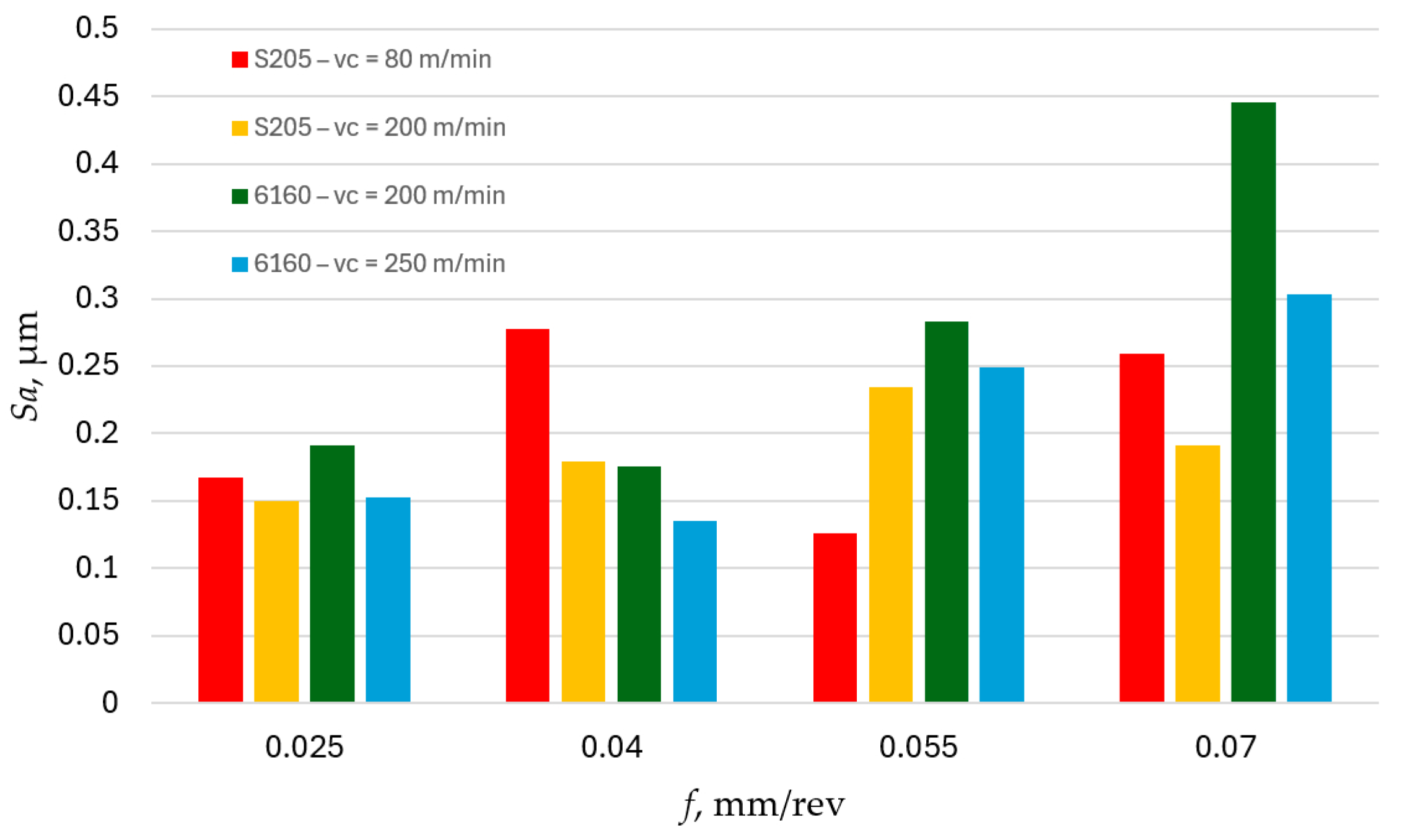
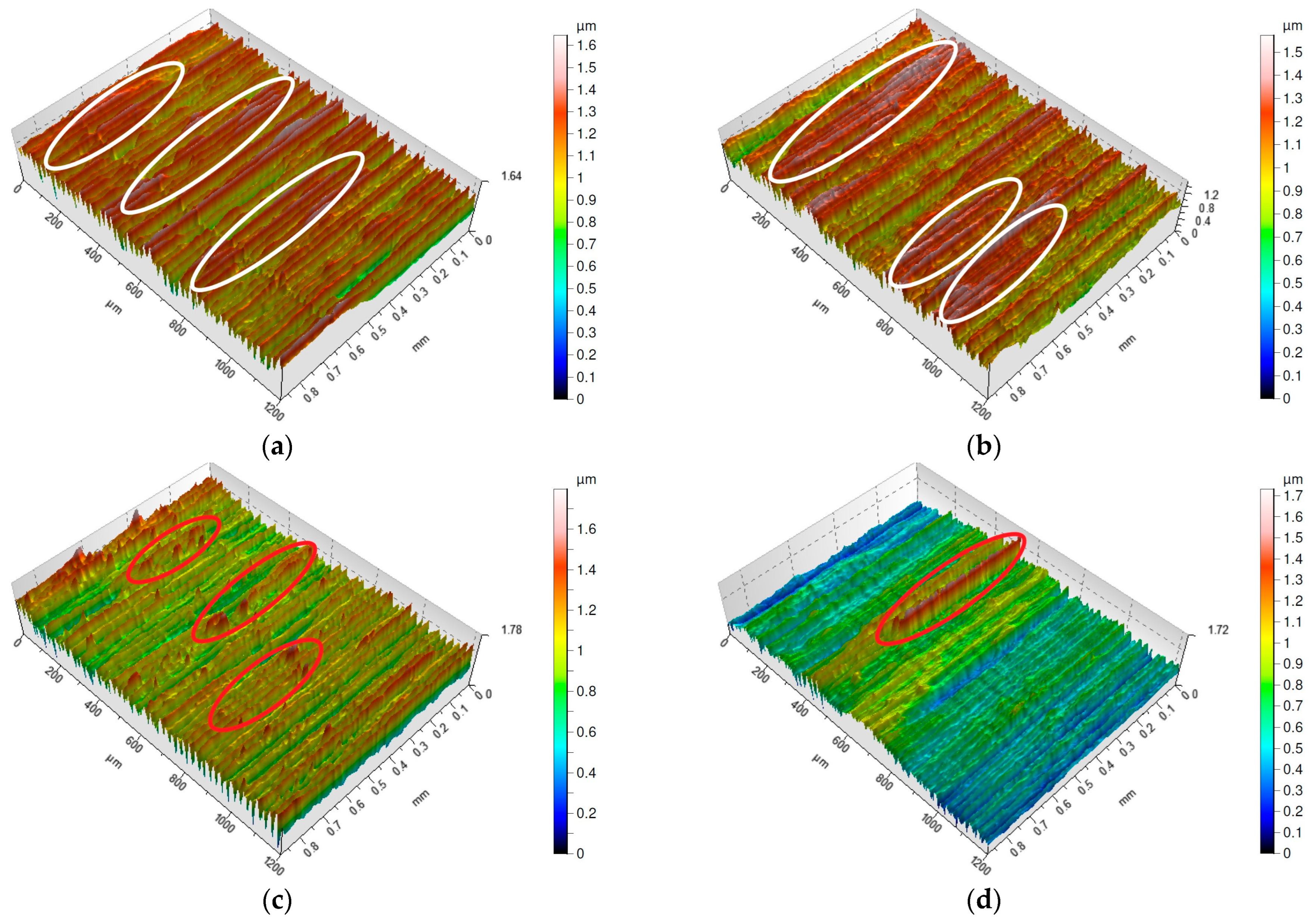
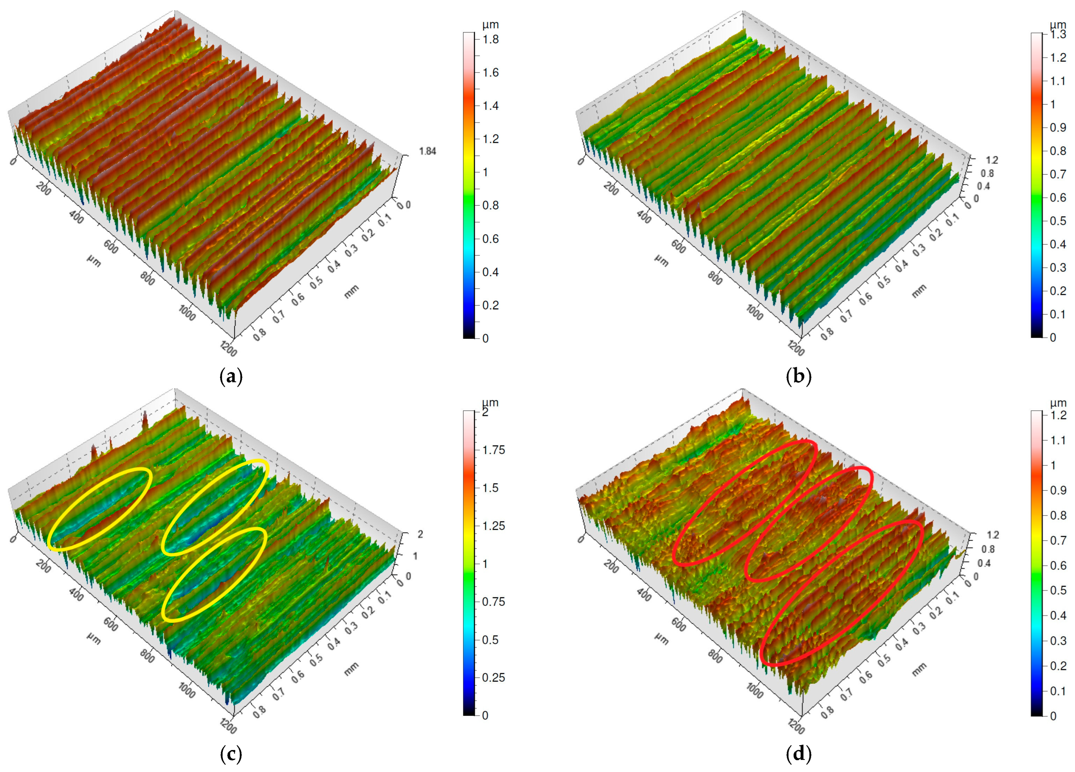
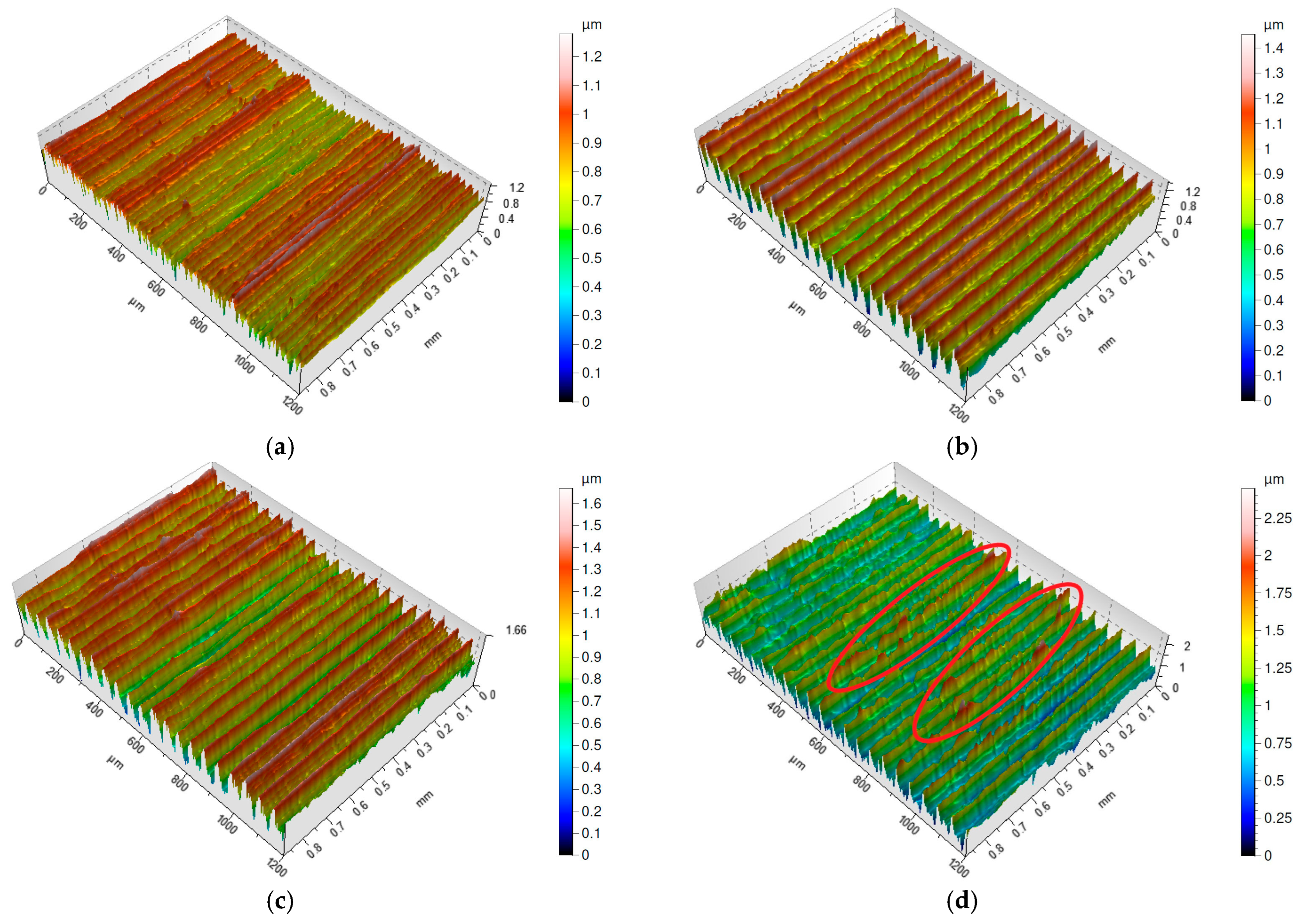
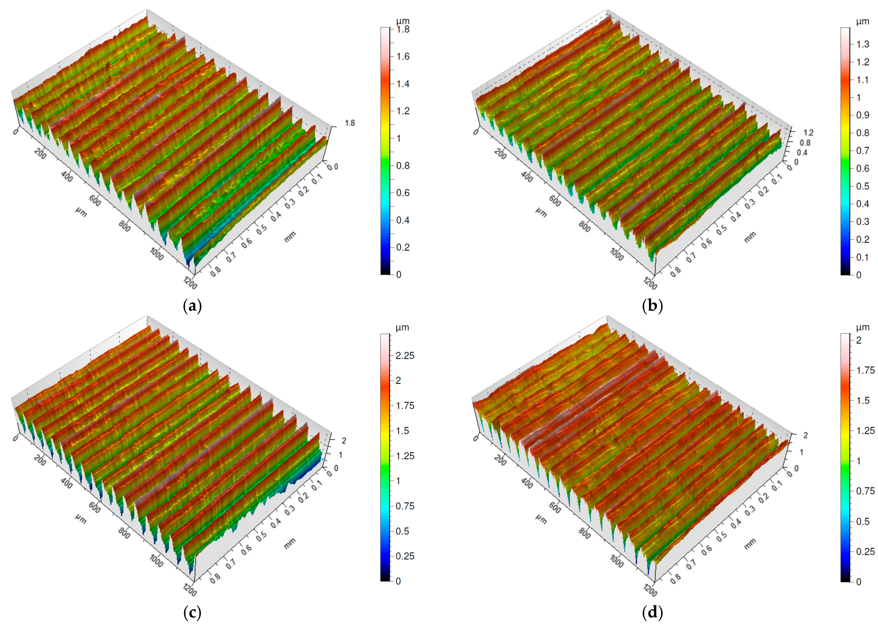
3.1. Surface Topography
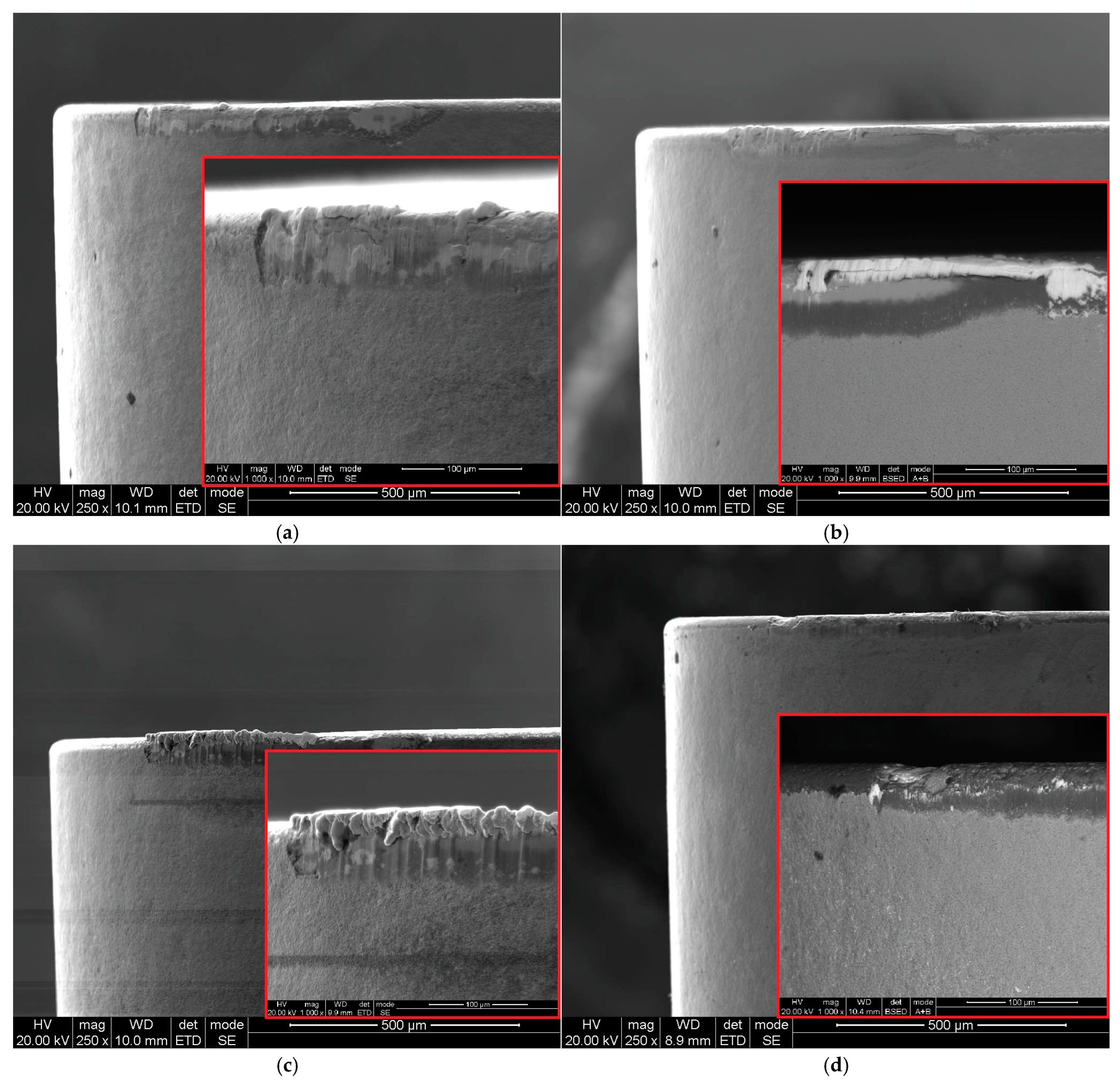
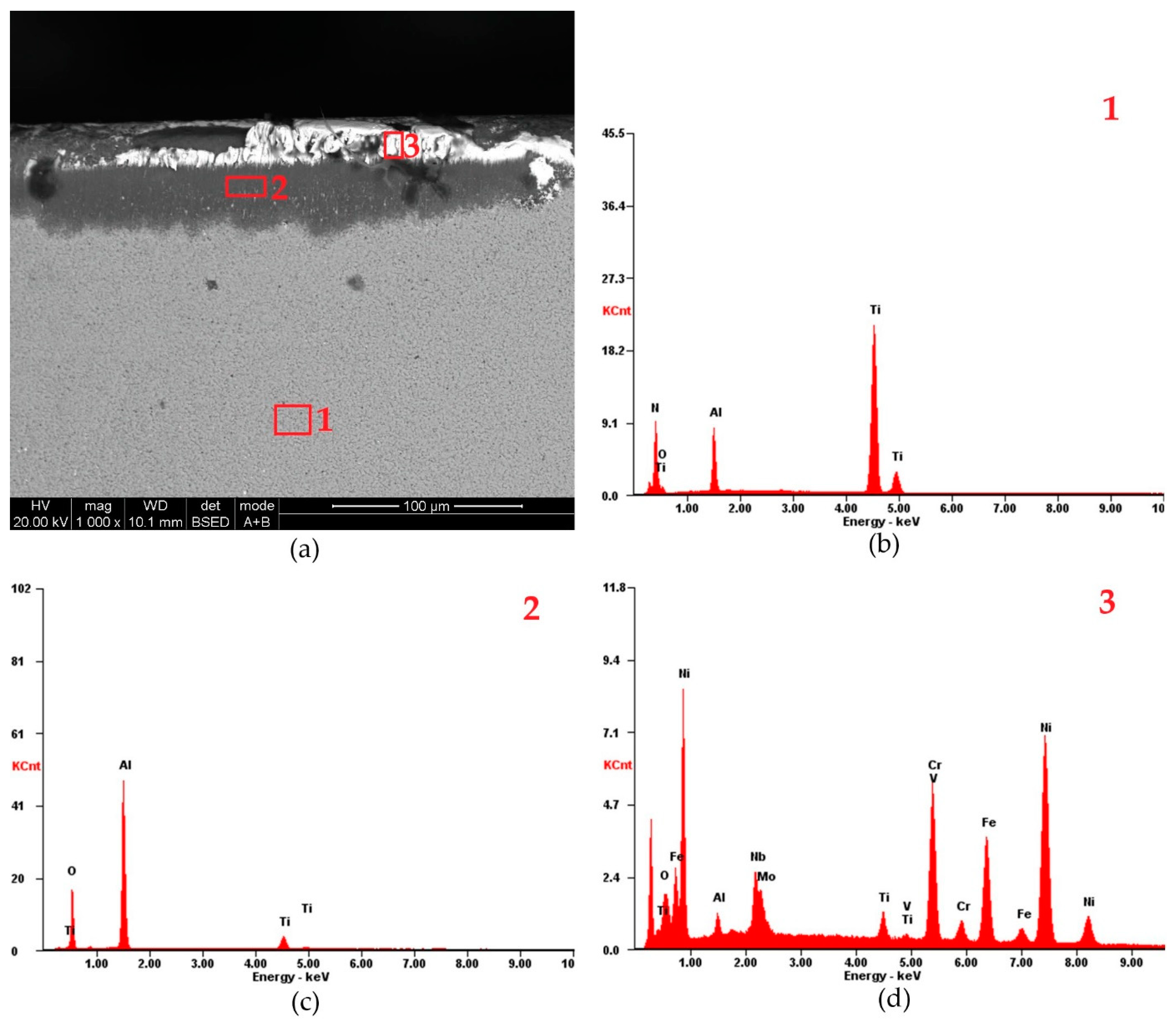
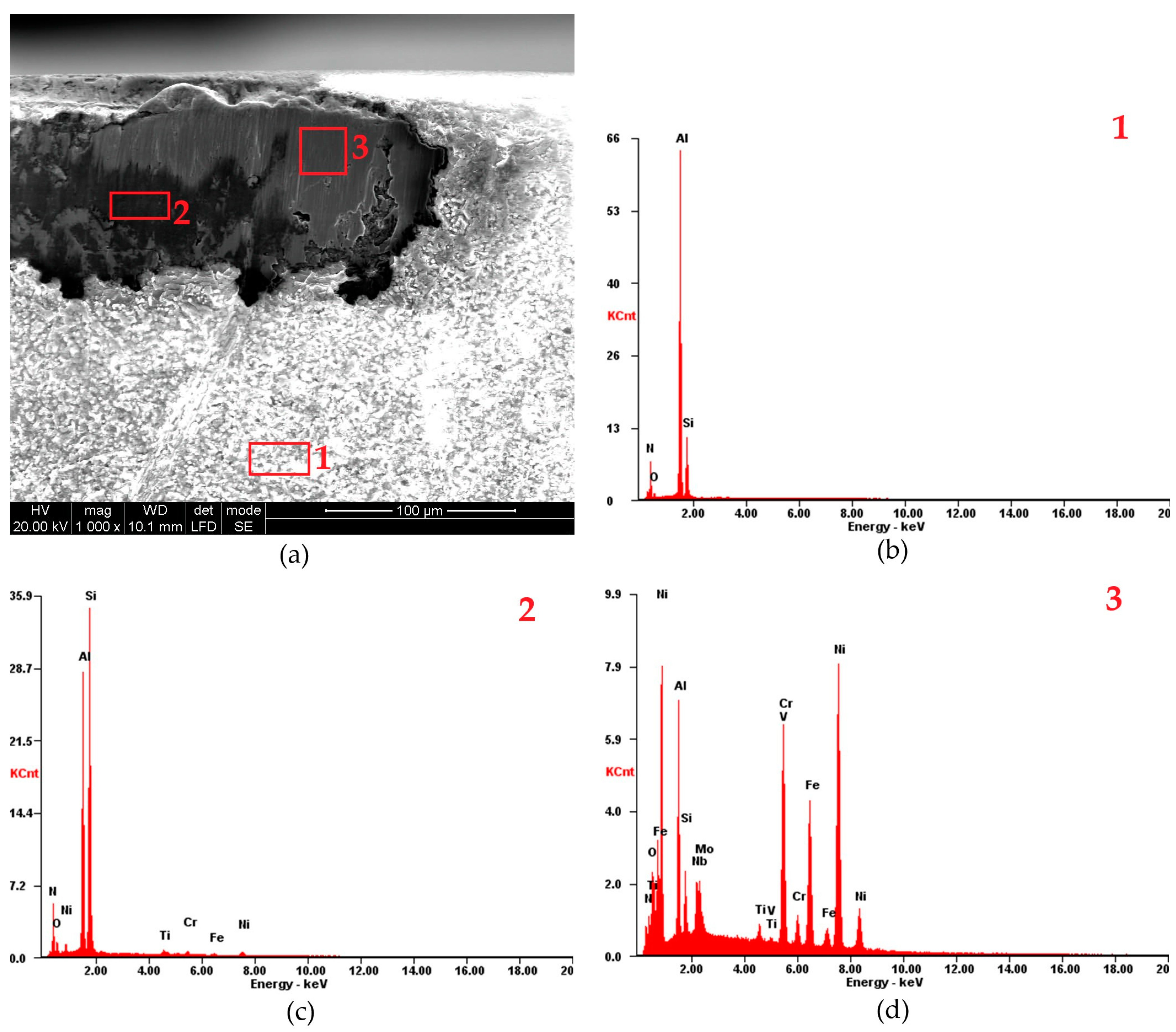
Figure 1 illustrates the relationship between the Sa parameter and feed rate f. The obtained Sa parameter values for different feed rates exhibit significant variation depending on the type of cutting tool used and the cutting speed. Only for a feed rate of f = 0.025 mm/rev do the recorded results show similar values. For the other feed rates applied, significant differences exist between the individual cutting tools. It is noteworthy that the highest Sa parameter values on surfaces machined with the ceramic 6160 tool were recorded for feed rates of f = 0.025 mm/rev, f = 0.055 mm/rev and f = 0.07 mm/rev. A similar trend was observed for surfaces machined with the carbide S205 tool, where the highest Sa values were recorded for feed rates of f = 0.025 mm/rev, f = 0.04 mm/rev, and f = 0.07 mm/rev. Lower roughness parameter Sa values for surfaces machined with the S205 carbide tools were achieved at a cutting speed of vc = 200 m/min, while for surfaces machined with the ceramic 6160 tools, lower Sa values were obtained at vc = 250 m/min. Therefore, increasing the cutting speed for both types of cutting tool materials positively affects the roughness parameter Sa. A similar conclusion was reached by Yildirim, Amigo and Kümmel. Yildirim et al. [27] machined Inconel 625 alloy using carbide tools with MQL (minimum quantity lubrication), cryogenic cooling, and CryoMQL. Amigo et al. [28] have machined Inconel 718 alloy using emulsion and CO2. Kümmel et al. [29] conducted studies using AISI 1045 steel and found that increasing the cutting speed reduces the built-up edge (BUE) on the cutting edge, positively impacting the surface quality of the machined part.
Comparing the obtained Sa parameter values after turning with S205 carbide tools and 6160 ceramic tools at the same cutting speed vc = 200 m/min, it can be observed that the S205 carbide tools produce surfaces with lower Sa roughness parameter values (Figure 1). This is particularly evident for the highest applied feed rate of f = 0.07 mm/rev, where the Sa parameter obtained with the ceramic 6160 tool is more than twice as high compared to the value achieved with the S205 carbide tool. The reduction of the Sa parameter was obtained by Suarez et al. [30] by using ultrasonic assisted machining. Compared to conventional machining, the Sa parameter was three times smaller.
Figure 2, Figure 3, Figure 4 and Figure 5 present isometric maps of the machined surfaces. Characteristic turning marks were observed on all analyzed surfaces. The surfaces obtained with a feed rate of f = 0.025 mm/rev exhibit similar Sa parameter values, but their isometric images differ (Figure 2a–d). High ridges were observed on surfaces machined with both S205 and 6160 tools. The difference between these surfaces is that on the S205-machined surfaces, distinct areas of high ridges can be identified (marked on figures by red circle), whereas on the 6160-machined surfaces, individual ridges appear sporadically (marked on figures by white circle). Additionally, on the surface machined at a cutting speed of vc = 200 m/min (Figure 2c), a higher frequency of high ridges was observed compared to the surface machined at vc = 250 m/min (Figure 2d).
From a functional standpoint, the S205-machined surfaces exhibit a more favorable topography. The isolated high ridges on the 6160-machined surfaces reduce contact between interacting surfaces [31].
Surfaces machined with a feed rate of f = 0.04 mm/rev, similar to those machined at f = 0.025 mm/rev, also exhibit characteristic turning marks (Figure 3a–d). However, these marks are more pronounced on surfaces machined with S205 carbide tools, whereas on surfaces machined with 6160 ceramic tools, they appear more blurred.
Interestingly, the surface machined with the 6160 ceramic tool at a cutting speed of vc = 250 m/min (Figure 3d) shows a lower Sa parameter value despite the presence of localized high ridges (marked on figure by red circle), compared to the surface machined with the same tool at vc = 200 m/min (Figure 3c). Additionally, the surface machined with the 6160 tool at vc = 200 m/min exhibits wide valleys (marked on figure by yellow circle) that are absent on the other surfaces machined at f = 0.04 mm/rev. This suggests that material removal may have been influenced by the built-up edge on the cutting tool [32].
Figure 4a–d presents the isometric maps of surfaces machined with S205 and 6160 inserts at a feed rate of f = 0.055 mm/rev. The isometric map obtained after turning with the S205 insert at a cutting speed of vc = 80 m/min (Figure 4a) clearly differs from the other surfaces machined with the same feed rate. It more closely resembles the isometric map obtained for the lowest tested feed rate, as distinguishing adjacent peaks is more difficult. This effect was likely influenced by the built-up edge (BUE) phenomenon. Interestingly, this surface exhibits the lowest Sa parameter value, being the only one with Sa < 0.15 µm.
The surface machined with the 6160 insert at a cutting speed of vc = 250 m/min (Figure 4d) is another example where high peaks were observed (marked on figure by red circle). Analyzing all tested surfaces, it becomes evident that high peaks occur exclusively on surfaces machined with the 6160 insert. However, whether these peaks appear individually or in specific regions, the surface roughness parameter Sa does not exceed 0.3 µm.
The isometric maps of surfaces machined with a feed rate of f = 0.07 mm/rev show that neither the surfaces machined with S205 inserts nor those machined with 6160 inserts exhibit individual high peaks (Figure 5a–d). The distances between adjacent ridges are evenly distributed. Among the four surfaces, the one machined with the 6160 insert stands out with narrower valleys, making it appear flatter (Figure 5d). A surface with this characteristic is more resistant to wear. Pawlus et al. [33] defined the Sp/Sz ratio as the coefficient of emptiness, which reached its lowest value for the surface machined with the 6160 insert at f = 0.07 mm/rev.

3.2. Tool Wear

Perez-Salinas et al. [34] demonstrated that cutting edge wear is related to chip vibration frequency. They confirmed that the frequency of chip generation decreases as flank wear increases. Based on Figure 6, it can therefore be inferred that higher chip vibration frequencies are associated with cutting edges made of S205-coated cemented carbides. In the case of these inserts, the flank wear VB did not exceed 0.08 mm for all tested feed rates. Significantly greater wear was recorded on inserts made of 6160 ceramics. Therefore, it can be assumed that machining with ceramic inserts is accompanied by lower chip vibration frequencies.
The effect of cutting speed on flank wear for S205 inserts is inconclusive. At both a cutting speed of vc = 80 m/min and vc = 200 m/min, the VB values are similar. However, for 6160 inserts, a clear influence of both cutting speed and feed rate on flank wear can be observed. An increase in feed rate leads to a reduction in flank wear, whereas an increase in cutting speed results in higher flank wear. The differences in VB wear values between the S205 and 6160 inserts are significant. While at a feed rate of f = 0.07 mm/rev, the wear of ceramic inserts is approximately twice that of cemented carbide inserts, at a feed rate of f = 0.025 mm/rev, the wear of ceramic inserts is more than three times greater than that of cemented carbide inserts.
Figure 7, Figure 8, Figure 9 and Figure 10 present wear symptoms of the S205 and 6160 inserts recorded on the rake and flank surfaces. A common feature observed in all tested tools is adhesive wear, including built-up edge (BUE) formation on both the rake and flank surfaces. The extent of wear varies depending on cutting parameters such as feed rate and cutting speed.
Machining with a feed rate of f = 0.025 mm/rev and a cutting speed of vc = 80 m/min results in BUE formation on both the cutting edge and the rake surface (Figure 7a). The BUE width on the rake surface exceeds the maximum chip thickness and measures 0.052 mm. Increasing the cutting speed to vc = 200 m/min intensifies BUE formation on the cutting edge (Figure 7b and Figure 8b).
Cutting with a feed of f = 0.07 mm/rev and a cutting speed of vc = 80 m/min favors the formation of a built-up edge on the cutting edge (Figure 7c and Figure 8c). However, machining with the same feed rate but a higher cutting speed of vc = 200 m/min leads to severe coating delamination on the cutting edge (Figure 7d). Khochtali et al. [35] stated that material loss on the rake surface is caused by the detachment of tool fragments along with adhered workpiece material. This phenomenon is intensified by increased coolant pressure. However, Figure 7 demonstrates that the amount of material loss on the cutting edge also depends on cutting parameters such as feed rate and cutting speed.
Figure 8 confirms that both feed rate and cutting speed influence the adhesion phenomenon. When machining at a feed rate of f = 0.025 mm/rev and a cutting speed of vc = 80 m/min, the machined material spreads across the rake surface. Increasing the cutting speed to vc = 200 m/min while maintaining the same feed rate results in the formation of a stable built-up edge on the cutting edge, which in this case protects the tool from abrasive wear on the flank surface.
For a higher feed rate of f = 0.07 mm/rev, a persistent BUE along the cutting edge was observed after machining at vc = 80 m/min. However, increasing the cutting speed to vc = 200 m/min does not promote BUE formation on the rake surface or the cutting edge.
The wear characteristics of the rake surface on the 6160 inserts differ from those observed on the S205 inserts. On the rake surface of the S205 inserts, a built-up edge formed, reflecting the cross-section of the chip. In the case of the 6160 inserts, the rake surface also exhibited a chip cross-section imprint, but only with scattered chip fragments within it (Figure 9a–d). This phenomenon is independent of feed rate and cutting speed. However, it was observed that increasing the cutting speed from 200 m/min (Figure 9c) to 250 m/min (Figure 8d) led to an increase in the number of microchips. Nevertheless, they do not form a compact BUE like the one observed on the S205 inserts.
Coelho et al. [36], who studied the wear of ceramic cutting tools when machining Inconel 718, demonstrated that the primary wear mechanism of these tools is notch wear. The conducted research confirmed that using a cutting speed of vc = 250 m/min with a feed rate of f = 0.025 mm/rev leads to an increase in notch wear (Figure 10b). This wear is twice as severe as that observed at a cutting speed of vc = 200 m/min (Figure 10a). This phenomenon was not observed at a feed rate of f = 0.07 mm/rev. In this case, increasing the cutting speed did not lead to a rise in notch wear. Therefore, the extent of notch wear depends on both the feed rate and the cutting speed. Additionally, it was noted that increasing the cutting speed reduces the extent of wear along the cutting edge of the 6160 inserts (Figure 10b,d). This effect was observed for both the lowest tested feed rate (f = 0.025 mm/rev) and the highest feed rate (f = 0.07 mm/rev).
The EDS analysis of the examined inserts was conducted for three points located on the flank faces of the S205 (Figure 11a) and 6160 (Figure 12a) inserts. During the analysis of the S205 insert at point 1, four elements were identified: Ti, N, Al, and O (Figure 11b). The first two elements originate from the TiN coating, while the latter two come from the Al2O3 layer. The presence of Al and O in point 1 could suggest partial removal of the TiN layer. However, EDS analyses performed on other inserts and at locations farther from the cutting edge yielded similar results. Therefore, the presence of Al and O elements at point 1 may be caused by the small thickness of the TiN layer, below 1 µm. The volumetric nature of the EDS analysis shows not only the elements of the surface layer, but also the elements of the Al2O3 layer. Therefore, the presence of Al and O elements at point 1 may be caused by the small thickness of the TiN layer, below 1 µm. The volumetric nature of the EDS analysis shows not only the elements of the surface layer, but also the elements of the next layer. At point 2 (Figure 11c), located 30 µm below the cutting edge, the detected elements were Al, O, and Ti. These results indicate that the TiN layer was removed.
Though trace amounts of Ti remained (Table 2). The removal of the TiN layer exposed the Al2O3 layer, which continued to protect the cutting tool. No elements of the cutting insert substrate (W, C or Co) were found in point 2. EDS analysis at point 3, located on the cutting edge (Figure 11d), confirmed the formation of a built-up edge. Elements such as Ni, Cr, and Fe, key components of Inconel 718, were detected. Additionally, Al and O were found, indicating that the Al2O3 layer was still intact and had not exposed the underlying TiCN layer adjacent to the WC-Co substrate. This suggests that the Al2O3 layer exhibits higher adhesion tendencies compared to the TiN layer, which was completely removed due to abrasive wear.
The EDS analysis conducted at point 1 of the 6160 insert reveals similar characteristics to those observed in the S205 insert. Specifically, no elements characteristic of the machined material were detected at this location (Figure 12b). The elements recorded at point 1 were Si, Al, O, and N (Table 3). Point 2 on the 6160 insert was located 40 µm below the cutting edge (Figure 12c). The EDS analysis at this point revealed trace amounts of the machined material (elements Ni, Cr, and Fe) as well as elements characteristic of the cutting insert itself, namely Si, Al, O, and N. This differentiates the 6160 insert from the S205 insert, as no machined material elements were detected in point 2 of the S205 insert. Notably, significant changes in the quantities of Al and Si were observed between points 1 and 2. In point 2, the Al content was 50% lower, while the Si content increased by 132% compared to point 1. At point 3 (Figure 12d), the EDS analysis confirmed a substantial presence of the machined material, with Ni, Cr, and Fe detected in concentrations of 45.04 wt%, 15.32 wt%, and 14.25 wt%, respectively.
The study by Zhuang et al. [37,38] demonstrated that the edge radius rn of the cutting tool influences tool temperature, tool life, surface roughness, and the microstructure of the machined surface layer. They determined that the optimal edge radius for tool longevity is rn = 15 µm. If the edge radius is smaller, the cutting edge undergoes rapid chipping. Conversely, a larger edge radius leads to increased grain deformation in the surface layer and higher surface roughness. Other researchers [39] also highlighted the significance of the cutting edge radius, identifying it as the primary factor affecting the minimum uncut chip thickness hmin. To evaluate the impact of feed rate and cutting speed on the cutting edge radius of the investigated inserts, microgeometry measurements were conducted [40]. The results are shown in Figure 13 and Figure 14. The average cutting edge radii of the new S205 and 6160 inserts are similar, measuring 36 µm (Figure 13) and 39 µm (Figure 14), respectively. However, an interesting trend emerged in the wear analysis, for the S205 inserts, the edge radii decreased regardless of the feed rate or cutting speed (Figure 13), while for the 6160 inserts, the edge radii increased under the same conditions (Figure 14). This discrepancy may be due to different wear mechanisms observed in the two insert types, as illustrated in Figure 7, Figure 8, Figure 9 and Figure 10. In the case of the S205 inserts, more built-up material was found on the rake face. In contrast, for the 6160 inserts, a greater amount of built-up material was observed on the flank face.

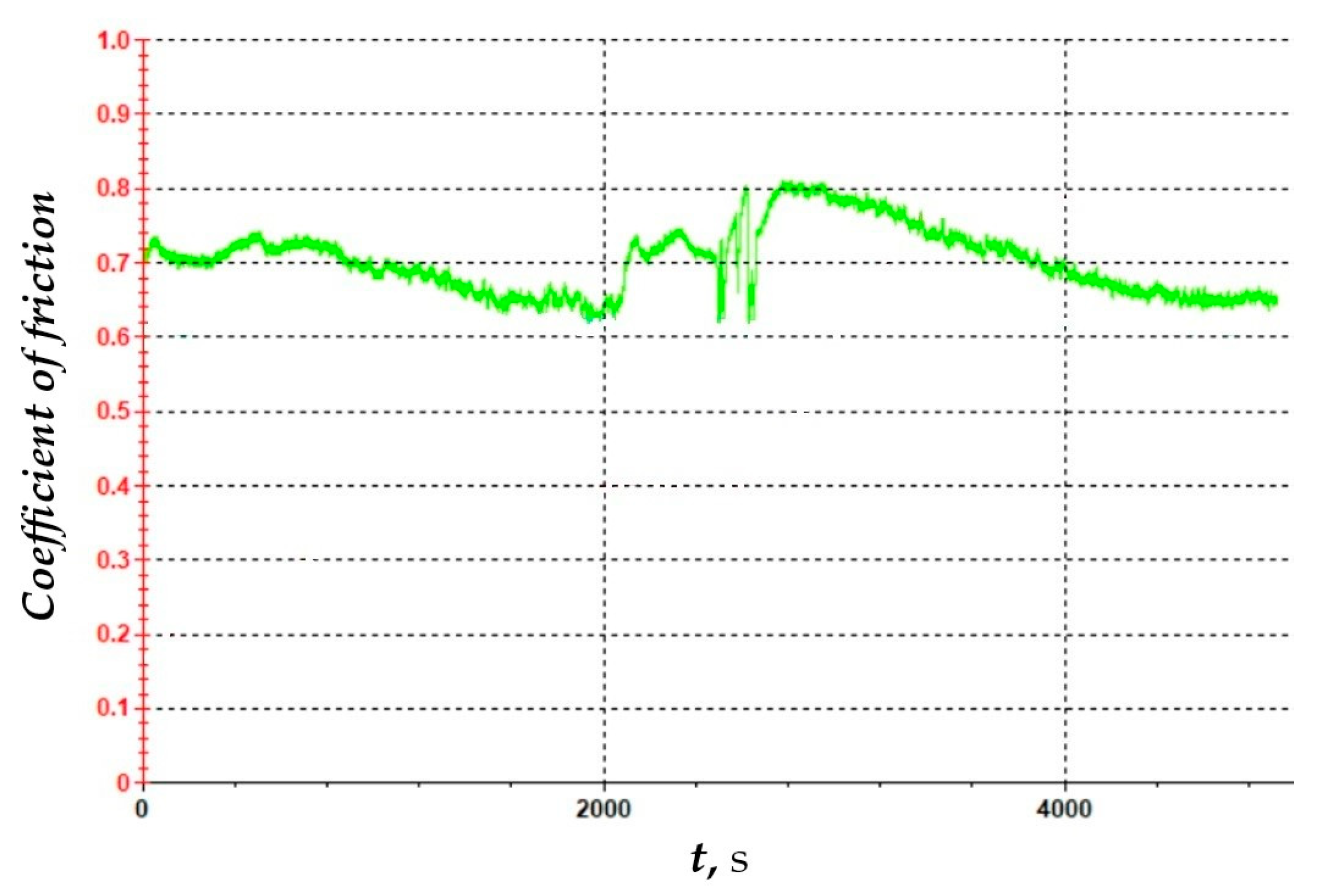
3.3. Coefficient of Friction

Abrasive wear is one of the dominant wear mechanisms in machining nickel-based alloys [41]. Therefore, the coefficient of friction of the cutting tool plays a significant role in the cutting process.
In study [42], the friction coefficient was determined for an AlTiN coating applied to a carbide cutting tool. Researchers found that the coefficient is variable over time and depends on the wear level of the cutting tool, with a maximum value of 0.85. The measured friction coefficient for the S205 insert is shown in Figure 15. It is important to note that the measurement was conducted over 80 min, whereas the tool life of inserts used for machining nickel alloys typically does not exceed 20 min. The obtained friction coefficient for the S205 insert with a TiCN/Al2O3/TiN coating applied via CVD method fluctuates around 0.7, which is approximately 20% lower than the AlTiN-coated insert. Efforts to reduce friction and thus extend tool life are focused on replacing conventional cooling/lubrication methods. One such approach was proposed by Sivalingam et al. [43], who used an atomized spray cutting fluid (ASCF), achieving an almost 40% increase in tool life.

4. Conclusions

Based on the research carried out, the following conclusions were formulated:
  • The dominant wear mechanisms of S205 and 6160 cutting inserts are abrasion and adhesion. The difference between these inserts lies in the fact that S205 inserts tend to form a built-up edge (BUE) on the rake face, whereas 6160 inserts exhibit a tendency to form a BUE on the flank face. Additionally, ceramic inserts 6160 have a greater tendency for notch wear.
  • Surface topography analysis revealed the formation of individual high ridges on surfaces machined with ceramic inserts. This phenomenon may result from BUE formation on the flank face, which is in direct contact with the machined surface. No individual high ridges were observed on surfaces machined with S205 inserts, where a BUE formed on the rake face.
  • The conducted research confirmed that both S205 and 6160 inserts can achieve a high-quality machined surface. The Sa parameter did not exceed 0.45 µm for any tested cutting conditions. Therefore, using these inserts in finish turning of Inconel 718 can be a viable alternative to grinding operations.
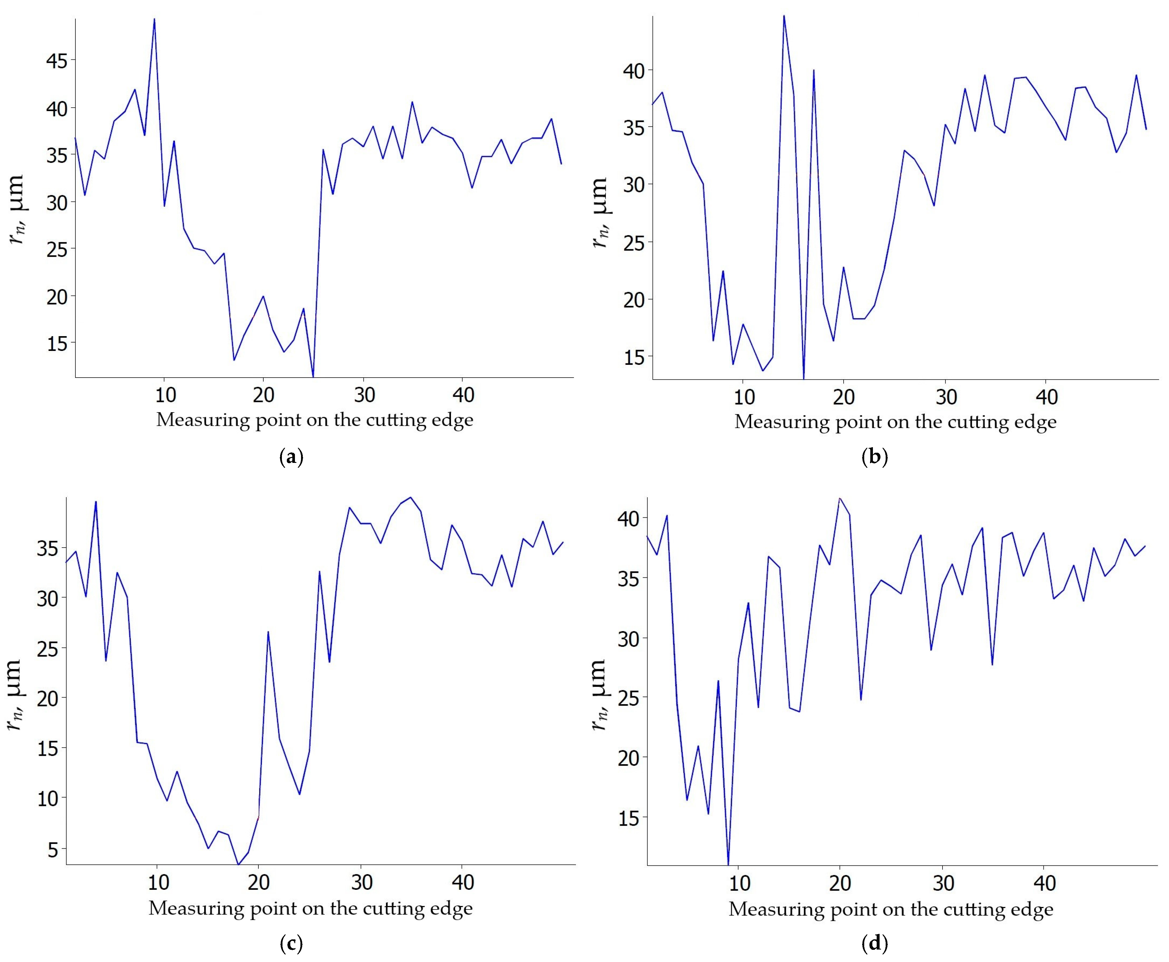
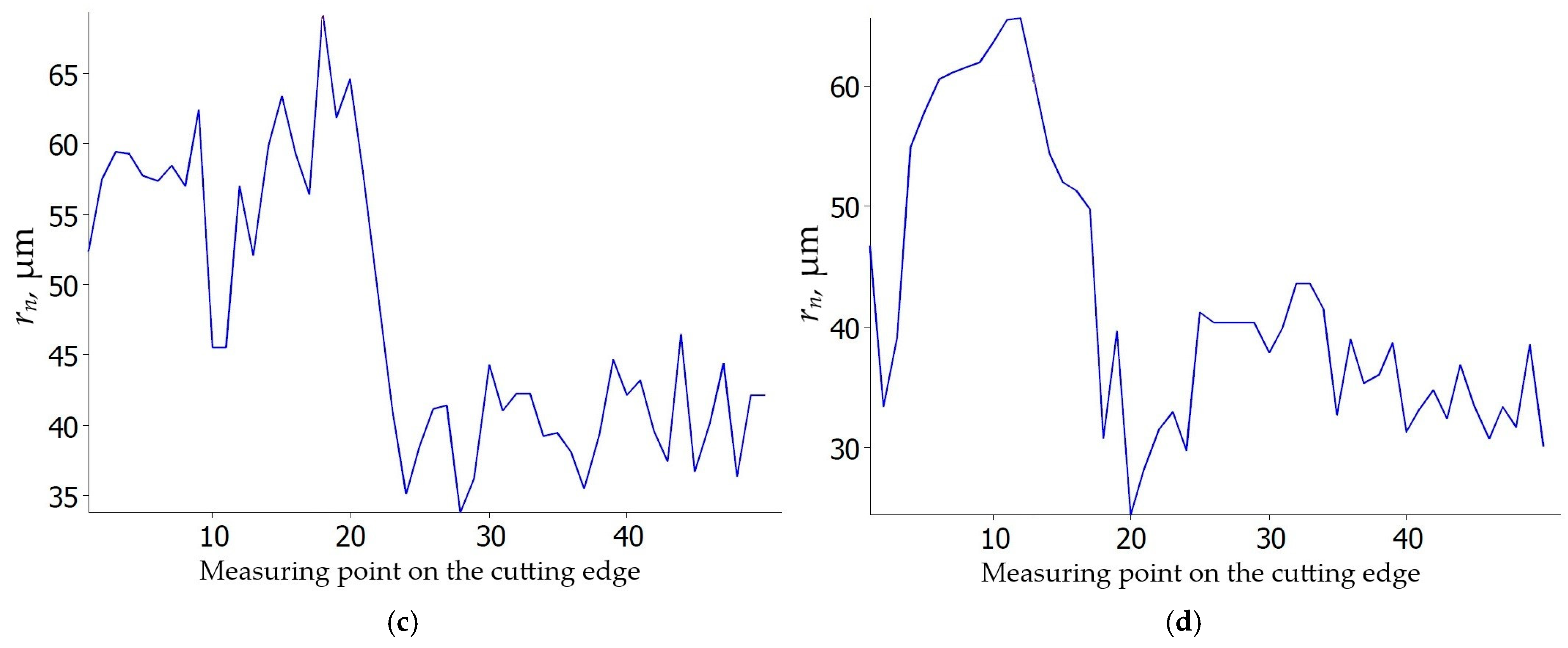
  • The effective cutting edge radius of S205 inserts decreases compared to the new inserts. In contrast, for 6160 inserts, the effective cutting edge radius increases. This is influenced by BUE, which forms on the flank face.
  • EDS analysis shows that the TiN coating is removed from the cutting insert, whereas the Al2O3 layer is more wear-resistant and provides a protective barrier. At the same time, the Al2O3 layer has a greater tendency for adhesion to the machined material.

Author Contributions

Conceptualization, P.S.; data curation, P.S.; formal analysis, P.S. and S.L.; funding acquisition, P.S. and J.P.; investigation, P.S. and J.P.; methodology, P.S. and S.L.; resources, P.S., S.L. and N.U.; software, P.S. and N.U.; supervision, S.L. and N.U.; validation, P.S. and S.L.; visualization, K.S. and B.K.; writing—original draft, P.S.; writing—review and editing, P.S. and S.L. All authors have read and agreed to the published version of the manuscript.

Funding

This research received no funding.

Institutional Review Board Statement

Not applicable.

Informed Consent Statement

Not applicable.

Data Availability Statement

Data are contained within the article.

Conflicts of Interest

The authors declare no conflicts of interest.

References

  1. Perez-Ruiz, J.D.; Marin, F.; Martínez, S.; Lamikiz, A.; Urbikain, G.; Lopez de Lacalle, L.N. Stiffening near-net-shape functional parts of Inconel 718 LPBF considering material anisotropy and subsequent machining issues. Mech. Syst. Signal Process. 2022, 168, 108675. [Google Scholar] [CrossRef]
  2. Rizea, A.D.; Ungureanu, E.R.A.; Negrea, D.A.; Moga, S.G.; Abrudeanu, M.; Petrescu, M.I.; Stefanoiu, R.; Haeussler, A.; Anghel, D.C.; Constantinescu, L.M. The Influence of Accidental Overheating on the Microstructure and Hardness of the Inconel 718 Alloy. Appl. Sci. 2025, 15, 3057. [Google Scholar] [CrossRef]
  3. Chen, Y.C.; Liao, Y.S. Study on wear mechanisms in drilling of Inconel 718 superalloy. J. Mater. Process. Technol. 2003, 140, 269–273. [Google Scholar] [CrossRef]
  4. Ahmed, N.; Mitrofanov, A.V.; Babitsky, V.I.; Silberschmidt, V.V. Analysis of material response to ultrasonic vibration loading in turning Inconel 718. Mater. Sci. Eng. 2006, A424, 318–325. [Google Scholar] [CrossRef]
  5. Rybicki, M.; Szablewski, P. Investigation of chips morphology after turning of materials applied in aerospace industry. MATEC Web Conf. 2017, 121, 03020. [Google Scholar] [CrossRef]
  6. Piorkowski, P.; Borkowski, W.; Skoczynski, W. Comprehensive Evaluation Method for High-Performance Milling of Inconel 718 Alloy. Appl. Sci. 2024, 14, 9023. [Google Scholar] [CrossRef]
  7. Smak, K.; Szablewski, P.; Legutko, S.; Krawczyk, B.; Miko, E. Investigation of the Influence of Anti-Wear Coatings on the Surface Quality and Dimensional Accuracy during Finish Turning of the Inconel 718 Alloy. Materials 2023, 16, 715. [Google Scholar] [CrossRef]
  8. Cantero, J.L.; Diaz-Alvarez, J.; Miguelez, M.H.; Marin, N.C. Analysis of tool wear patterns in finishing turning of Inconel 718. Wear 2013, 297, 885–894. [Google Scholar] [CrossRef]
  9. Thakur, A.; Gangopadhyay, S. Dry machining of nickel-based super alloy as a sustainable alternative using TiN/TiAlN coated tool. J. Clean. Prod. 2016, 129, 256–268. [Google Scholar] [CrossRef]
  10. Sivalingam, V.; Zhao, Y.; Thulasiram, R.; Sun, J.; Kai, G.; Nagamalai, T. Machining behaviour, surface integrity and tool wear analysis in environment friendly turning of Inconel 718 alloy. Measurement 2021, 174, 109028. [Google Scholar] [CrossRef]
  11. Zhao, J.F.; Liu, Z.Q.; Shen, Q.; Wang, B.; Wang, Q.Q. Investigation of cutting temperature during turning Inconel 718 with (Ti,Al)N PVD coated cemented carbide tools. Materials 2018, 11, 1281. [Google Scholar] [CrossRef] [PubMed]
  12. Hua, Y.; Liu, Z. Effects of cutting parameters and tool nose radius on surface roughness and work hardening during dry turning Inconel 718. Int. J. Adv. Manuf. Technol. 2018, 96, 2421–2430. [Google Scholar] [CrossRef]
  13. Park, K.H.; Yang, G.D.; Lee, D.Y. Tool wear analysis on coated and uncoated carbide tools in Inconel machining. Int. J. Precis. Eng. Manuf. 2015, 16, 1639–1645. [Google Scholar] [CrossRef]
  14. Pereira, O.; Urbikain, G.; Rodríguez, A.; Fernández-Valdivielso, A.; Calleja, A.; Ayesta, I.; López de Lacalle, L.N. Internal cryolubrication approach for Inconel 718 milling. Procedia Manuf. 2017, 13, 89–93. [Google Scholar] [CrossRef]
  15. Khanna, N.; Airao, J.; Nirala, C.K.; Krolczyk, G.M. Novel sustainable cryo-lubrication strategies for reducing tool wear during ultrasonic-assisted turning of Inconel 718. Tribol. Int. 2022, 174, 107728. [Google Scholar] [CrossRef]
  16. Bagherzadeh, A.; Budak, E. Investigation of machinability in turning of difficult-to-cut materials using a new cryogenic cooling approach. Tribol. Int. 2018, 119, 510–520. [Google Scholar] [CrossRef]
  17. Danish, M.; Gupta, M.K.; Rubaiee, S.; Ahmed, A.; Korkmaz, M.E. Influence of hybrid cryo-MQL lubri-cooling strategy on the machining and tribological characteristics of Inconel 718. Tribol. Int. 2021, 163, 107178. [Google Scholar] [CrossRef]
  18. Peng, Z.; Zhang, X.; Zhang, D. Performance evaluation of high-speed ultrasonic vibration cutting for improving machinability of Inconel 718 with coated carbide tools. Tribol. Int. 2021, 155, 106766. [Google Scholar] [CrossRef]
  19. Chaabani, S.; Arrazola, P.J.; Ayed, Y.; Madariaga, A.; Tidu, A.; Germain, G. Comparison between cryogenic coolants effect on tool wear and surface integrity in finish turning of Inconel 718. J. Mater. Process. Technol. 2020, 285, 116780. [Google Scholar] [CrossRef]
  20. Musavi, S.H.; Davoodi, B.; Niknam, S.A. Effects of reinforced nanoparticles with surfactant on surface quality and chip formation morphology in MQL-turning of superalloys. J. Manuf. Process. 2019, 40, 128–139. [Google Scholar] [CrossRef]
  21. Mohsan, A.U.H.; Zhanqiang, L.; Padhy, K.G. A review on the progress towards improvement in surface integrity of Inconel 718 under high pressure and flood cooling conditions. Int. J. Adv. Manuf. Technol. 2016, 91, 423–428. [Google Scholar] [CrossRef]
  22. Szablewski, P.; Legutko, S.; Mróz, A.; Garbiec, D.; Czajka, R.; Smak, K.; Krawczyk, B. Surface Topography Description after Turning Inconel 718 with a Conventional, Wiper and Special Insert Made by the SPS Technique. Materials 2023, 16, 949. [Google Scholar] [CrossRef] [PubMed]
  23. Zhao, J.; Liu, Z.; Wang, B.; Hua, Y.; Wang, Q. Cutting temperature measurement using an improved two-color infrared thermometer in turning Inconel 718 with whisker-reinforced ceramic tools. Ceram. Int. 2018, 44, 19002–19007. [Google Scholar] [CrossRef]
  24. Qadri, S.I.A.; Harmain, G.A.; Wani, M.F. The effect of cutting speed and work piece hardness on turning performance of nickel based super Alloy-718 using ceramic cutting inserts. Eng. Res. Express 2020, 2, 025018. [Google Scholar] [CrossRef]
  25. Qadri, S.I.A.; Harmain, G.A.; Wani, M.F. Influence of Tool Tip Temperature on Crater Wear of Ceramic Inserts During Turning Process of Inconel-718 at Varying Hardness. Tribol. Ind. 2020, 42, 310–326. [Google Scholar] [CrossRef]
  26. Zhou, J.; Bushlya, V.; Stahl, J. An investigation of surface damage in the high speed turning of Inconel 718 with use of whisker reinforced ceramic tools. J. Mater. Process. Technol. 2012, 212, 372–384. [Google Scholar] [CrossRef]
  27. Yildirim, C.V.; Kıvak, T.; Sarıkaya, M.; Sirin, S. Evaluation of tool wear, surface roughness/topography and chip morphology when machining of Ni-based alloy 625 under MQL, cryogenic cooling and CryoMQL. J. Mater. Res. Technol. 2020, 9, 2079–2092. [Google Scholar] [CrossRef]
  28. Amigo, F.J.; Urbikain, G.; Pereira, O.; Fernández-Lucio, P.; Fernández-Valdivielso, A.; López de Lacalle, L.N. Combination of high feed turning with cryogenic cooling on Haynes 263 and Inconel 718 superalloys. J. Manuf. Process. 2020, 58, 208–222. [Google Scholar] [CrossRef]
  29. Kümmel, J.; Gibmeier, J.; Müller, E.; Schneider, R.; Schulze, V.; Wanner, A. Detailed analysis of microstructure of intentionally formed built-up edges for improving wear behaviour in dry metal cutting process of steel. Wear 2014, 311, 21–30. [Google Scholar] [CrossRef]
  30. Suárez, A.; Veiga, F.; Polvorosa, R.; Artaza, T.; Holmberg, J.; López de lacalle, L.N.; Wretland, A. Surface integrity and fatigue of non-conventional machined Alloy 718. J. Manuf. Process. 2019, 48, 44–50. [Google Scholar] [CrossRef]
  31. Królczyk, G.M.; Maruda, R.W.; Królczyk, J.B.; Nieslony, P.; Wojciechowski, S.; Legutko, S. Parametric and nonparametric description of the surface topography in the dry and MQCL cutting conditions. Measurement 2018, 121, 225–239. [Google Scholar] [CrossRef]
  32. Ning, F.; Wang, F.; Jia, Z.; Ma, J. Chip morphology and surface roughness in high-speed milling of nickel-based superalloy Inconel 718. Int. J. Mach. Mach. Mater. 2014, 15, 285–299. [Google Scholar] [CrossRef]
  33. Pawlus, P.; Reizer, R.; Zelasko, W. Prediction of parameters of equivalent sum rough surfaces. Materials 2020, 13, 4898. [Google Scholar] [CrossRef] [PubMed]
  34. Pérez-Salinas, C.; López de Lacalle, L.N.; del Olmo, A.; Kumar, C.S. The relationship between the cutting-edge, tool wear, and chip formation during Inconel 718 dry cutting. Int. J. Adv. Manuf. Technol. 2024, 132, 6001–6017. [Google Scholar] [CrossRef]
  35. Khochtali, H.; Ayed, Y.; Zemzemi, F.; Bensalem, W. Tool wear characteristics in rough turning of Inconel 718 with coated carbide tool under conventional and high-pressure coolant supplies. Int. J. Adv. Manuf. Technol. 2021, 114, 2371–2386. [Google Scholar] [CrossRef]
  36. Coelho, R.T.; Silva, L.R.; Braghini, A.; Bezerra, A.A. Some effects of cutting edge preparation and geometric modifications when turning Inconel 718 at high cutting speeds. J. Mater. Process. Technol. 2004, 148, 147–153. [Google Scholar] [CrossRef]
  37. Zhuang, K.; Fu CWeng JHu, C. Cutting edge microgeometries in metal cutting: A review. Int. J. Adv. Manuf. Technol. 2021, 116, 2045–2092. [Google Scholar] [CrossRef]
  38. Zhuang, K.; Huang, Y.; Hu, C.; Wang, J.; Zou, L. An improved approach to tool life promotion concerning cutting edge microgeometry. Int. J. Adv. Manuf. Technol. 2023, 126, 1717–1731. [Google Scholar] [CrossRef]
  39. Devillez, A.; Schneider, F.; Dominiak, S.; Dudzinski, D.; Larrouquere, D. Cutting forces and wear in dry machining of Inconel 718 with coated carbide tools. Wear 2007, 262, 931–942. [Google Scholar] [CrossRef]
  40. Szablewski, P. Tribological behavior of Inconel 718 alloy when cutting with a carbide insert prepared using the SPS technique under dry and lubricated sliding conditions. Tribol. Int. 2024, 199, 109951. [Google Scholar] [CrossRef]
  41. Xavior, M.A.; Manohar, M.; Jeyapandiarajan, P.; Madhukar, P.M. Tool wear assessment during machining of Inconel 718. Procedia Eng. 2017, 174, 1000–1008. [Google Scholar] [CrossRef]
  42. Grzesik, W.; Niesłony, P.; Habrat, W.; Sieniawski, J.; Laskowski, P. Investigation of tool wear in the turning of Inconel 718 superalloy in terms of process performance and productivity enhancement. Tribol. Int. 2018, 118, 337–346. [Google Scholar] [CrossRef]
  43. Sivalingam, V.; Zan, Z.; Sun, J.; Selvam, B.; Gupta, M.K.; Jamil, M.; Mia, M. Wear behaviour of whisker-reinforced ceramic tools in the turning of Inconel 718 assisted by an atomized spray of solid lubricants. Tribol. Int. 2020, 148, 106235. [Google Scholar] [CrossRef]
Figure 1. The impact of feed f on the variability of roughness parameter Sa.
Applsci 15 04265 g001
Figure 2. Surface morphology of Inconel 718 after turning with feed rate f = 0.025 mm/rev: (a) vc = 80 m/min, carbide insert S205; (b) vc = 200 m/min, carbide insert S205; (c) vc = 200 m/min, ceramic insert 6160; (d) vc = 250 m/min, ceramic insert 6160.
Applsci 15 04265 g002
Figure 3. Surface morphology of Inconel 718 after turning with feed rate f = 0.04 mm/rev: (a) vc = 80 m/min, carbide insert S205; (b) vc = 200 m/min, carbide insert S205; (c) vc = 200 m/min, ceramic insert 6160; (d) vc = 250 m/min, ceramic insert 6160.
Applsci 15 04265 g003
Figure 4. Surface morphology of Inconel 718 after turning with feed rate f = 0.055 mm/rev: (a) vc = 80 m/min, carbide insert S205; (b) vc = 200 m/min, carbide insert S205; (c) vc = 200 m/min, ceramic insert 6160; (d) vc = 250 m/min, ceramic insert 6160.
Applsci 15 04265 g004
Figure 5. Surface morphology of Inconel 718 after turning with feed rate f = 0.07 mm/rev: (a) vc = 80 m/min, carbide insert S205; (b) vc = 200 m/min, carbide insert S205; (c) vc = 200 m/min, ceramic insert 6160; (d) vc = 250 m/min, ceramic insert 6160.
Applsci 15 04265 g005
Figure 6. The impact of feed f on the flank wear VB.
Applsci 15 04265 g006
Figure 7. SEM images of rake face of carbide inserts S205: (a) vc = 80 m/min, f = 0.025 mm/rev; (b) vc = 200 m/min, f = 0.025 mm/rev; (c) vc = 80 m/min, f = 0.07 mm/rev; (d) vc = 200 m/min, f = 0.07 mm/rev.
Applsci 15 04265 g007
Figure 8. SEM images of flank face of carbide inserts S205: (a) vc = 80 m/min, f = 0.025 mm/rev; (b) vc = 200 m/min, f = 0.025 mm/rev; (c) vc = 80 m/min, f = 0.07 mm/rev; (d) vc = 200 m/min, f = 0.07 mm/rev.
Applsci 15 04265 g008
Figure 9. SEM images of rake face of ceramic inserts 6160: (a) vc = 80 m/min, f = 0.025 mm/rev; (b) vc = 200 m/min, f = 0.025 mm/rev; (c) vc = 80 m/min, f = 0.07 mm/rev; (d) vc = 200 m/min, f = 0.07 mm/rev.
Applsci 15 04265 g009
Figure 10. SEM images of flank face of ceramic inserts 6160: (a) vc = 80 m/min, f = 0.025 mm/rev; (b) vc = 200 m/min, f = 0.025 mm/rev; (c) vc = 80 m/min, f = 0.07 mm/rev; (d) vc = 200 m/min, f = 0.07 mm/rev.
Applsci 15 04265 g010
Figure 11. EDS analysis of the flank face of S205 insert: (a) SEM image of flank face, (b) EDS analysis at point 1, (c) EDS analysis at point 2, (d) EDS analysis at point 3; f = 0.07 mm/rev, vc = 200 m/min.
Applsci 15 04265 g011
Figure 12. EDS analysis of the flank face of 6160 insert: (a) SEM image of flank face, (b) EDS analysis at point 1, (c) EDS analysis at point 2, (d) EDS analysis at point 3; f = 0.07 mm/rev, vc = 200 m/min.
Applsci 15 04265 g012
Figure 13. Cutting edge radius rn of S205 carbide insert: (a) vc = 80 m/min, f = 0.025 mm/rev; (b) vc = 200 m/min, f = 0.025 mm/rev; (c) vc = 80 m/min, f = 0.07 mm/rev; (d) vc = 200 m/min, f = 0.07 mm/rev.
Applsci 15 04265 g013
Figure 14. Cutting edge radius rn of 6160 ceramic insert: (a) vc = 200 m/min, f = 0.025 mm/rev; (b) vc = 250 m/min, f = 0.025 mm/rev; (c) vc = 200 m/min, f = 0.07 mm/rev; (d) vc = 250 m/min, f = 0.07 mm/rev.
Applsci 15 04265 g014aApplsci 15 04265 g014b
Figure 15. Coefficient of friction plot vs. time.
Applsci 15 04265 g015
Table 1. Chemical composition of Inconel 718 used in the tests.
ElementNiCrFeNbMoTiAlSi
% weight53.8416.8717.234.454.591.351.380.29
Table 2. Chemical EDS analysis of the flank face in points 1–3 from Figure 11 (f = 0.07 mm/rev, vc = 200 m/min).
Weight %
Point No.NiCrFeOVAlNbTiMoN
1 5.67 13.07 65.49 15.76
2 39.74 50.65 9.61
349.6516.3115.353.850.131.67.82.183.13
Atom %
Point No.NiCrFeOVAlNbTiMoN
1 10.64 14.54 41.04 33.78
2 54.45 41.15 4.4
344.5416.5214.4812.660.133.124.422.41.72
Table 3. Chemical EDS analysis of the flank face in points 1–3 from Figure 12 (f = 0.07 mm/rev, vc = 200 m/min).
Weight %
Point No.NiCrFeOVAlNbTiMoSiN
1 3.39 52.86 18.8624.89
22.861.290.895.03 24.81 1.16 43.8420.11
345.0415.3214.253.710.1310.274.80.922.992.58
Atom %
Point No.NiCrFeOVAlNbTiMoSiN
1 4.59 42.41 14.5338.47
21.120.570.377.24 21.17 0.56 35.9333.05
336.0913.8612.0110.90.1217.912.430.91.474.31
Disclaimer/Publisher’s Note: The statements, opinions and data contained in all publications are solely those of the individual author(s) and contributor(s) and not of MDPI and/or the editor(s). MDPI and/or the editor(s) disclaim responsibility for any injury to people or property resulting from any ideas, methods, instructions or products referred to in the content.

