Mathematical Study of a Product-Gripping Mechanism for Industrial Transportation
Abstract
1. Introduction
2. Materials and Methods
- -
- Identify the mathematical calculation relationships required to determine the value of various components of the mechanism. Only their final forms are presented in this paper.
- -
- Realization of the mechanism operation by means of a simulation program. For this purpose, the use of the Linkage program (free program) was chosen.
- -
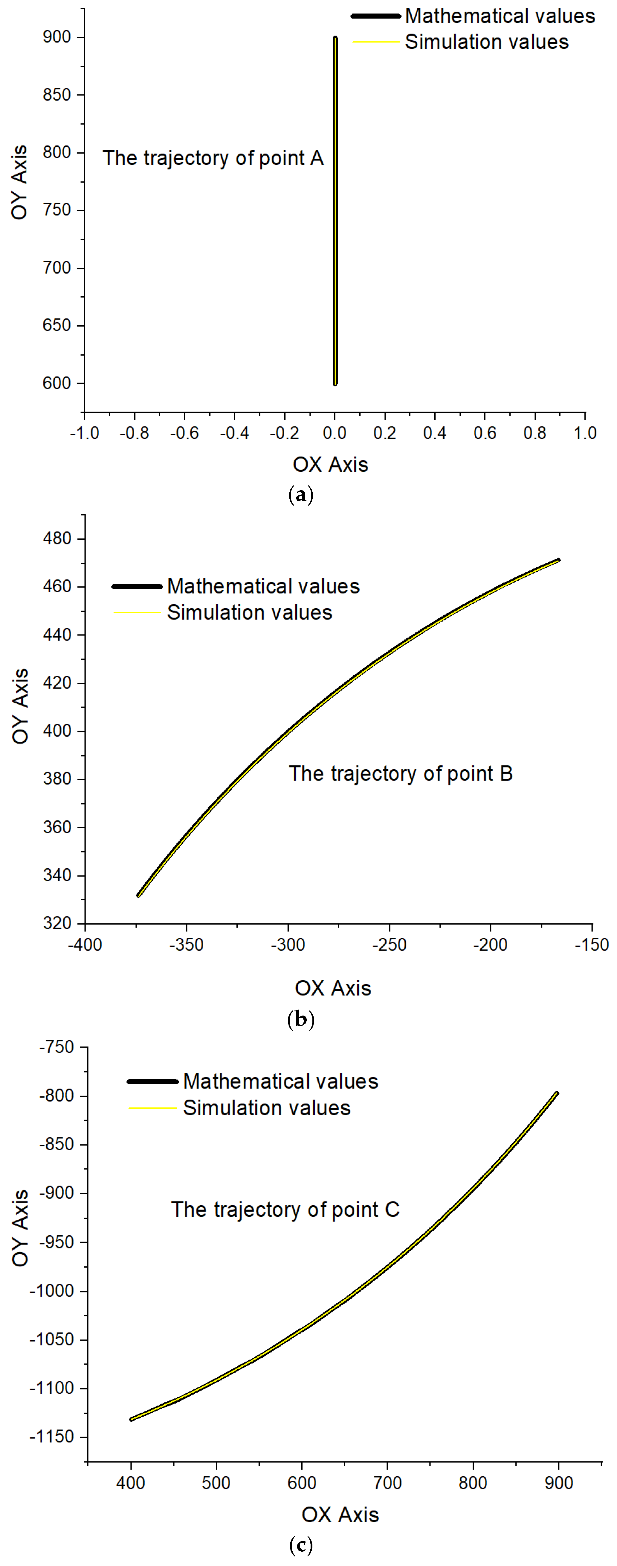
- A comparison was made between the values obtained using the two work methods: mathematical and simulation.
- -
- Mathcad v.15 (PTC Mathcad) [52] was used to perform mathematical calculations using the computational relations corresponding to the coordinates of the analyzed points.
- -
- Linkage v. 3.11.3 (developed by David M. Rector) [53] was used to simulate the movement of the studied mechanism and to verify the correctness of the results obtained from the mathematical calculation.
- -
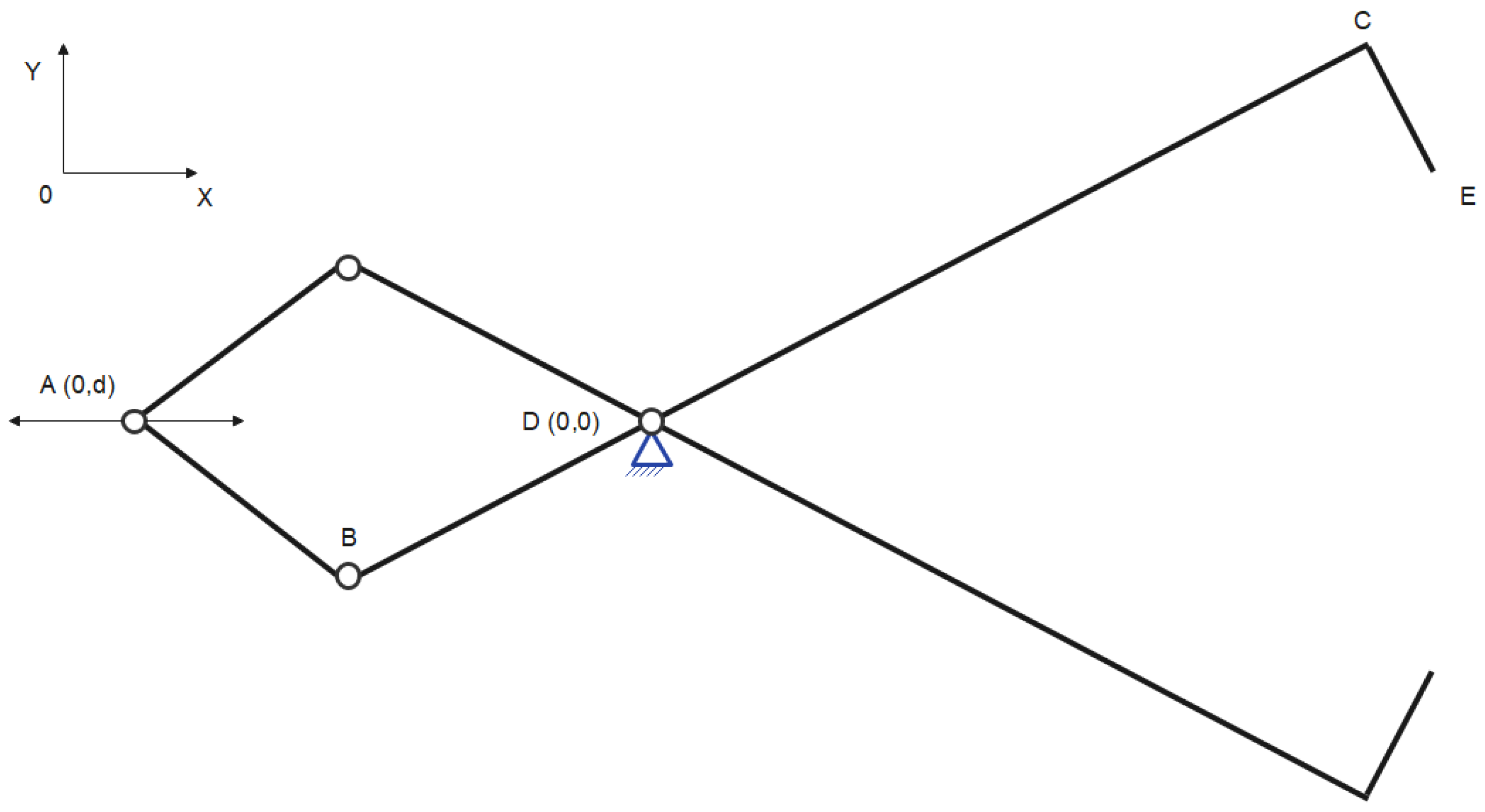
- Coupling (Figure 2):
- The fixed position of coupling A with coordinates (0, d), where the coordinate is 0 on the OX axis, and for the OY axis, it is d (distance from the origin of the OY axis to coupling A).
- Coupling B—mechanism articulation.
- Coupling D—fixed and positioned at the origin of the coordinate system.
- Coupling C—rigid, to which the CE element is connected.
- Coupling E—the end of the CE element, representing the zone of contact between the lifting mechanism and the moved product.
- -
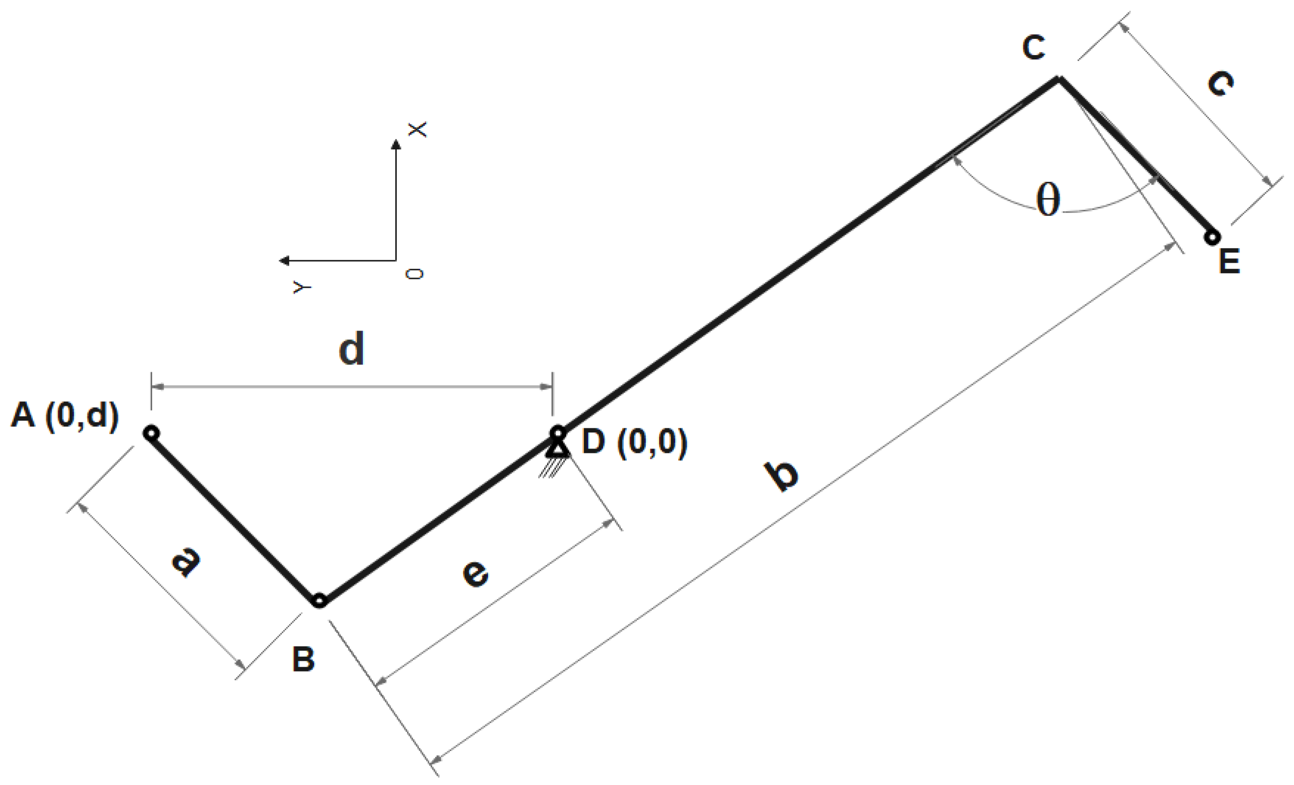
- Binary elements (Figure 3):
- Element AB, for which its dimensions are a.
- Element BC, for which its dimensions are b.
- Element CE, for which its dimensions are c.
- Element BD, for which its dimensions are e.
- -
- Angle θ is the angle generated by elements BC and CE (Figure 3). The value of the angle is given by the device and can be modified according to the type and nature of the material used. The CE element is rigidly attached to the BC element.
- -
- The mechanism is analyzed in relation to a coordinate system with an origin corresponding to point D.
- -
- Points A and D are on the same axis OY.
- -
- The distance between points A and D varies. The movement of point A allows the closing or opening of the gripping claws (EC element) by decreasing or increasing the distance between point E and the vertical OY axis, thus allowing the operation of gripping or detaching the load.
- -
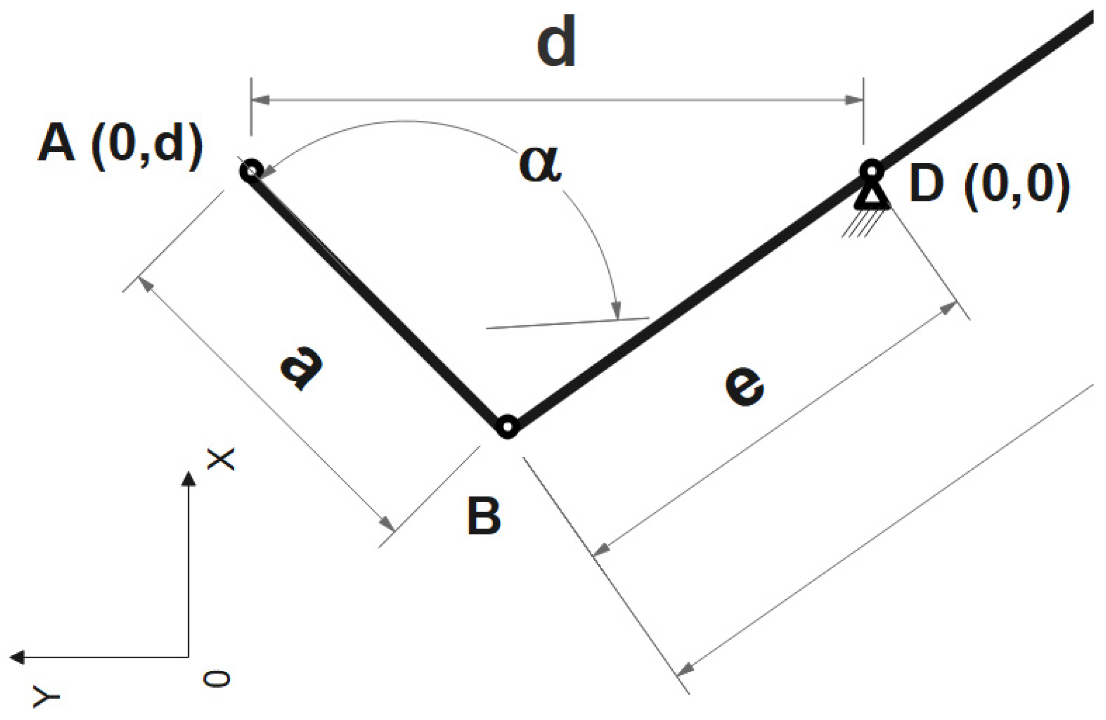
- As a result of the movement of point A, several elements of the mechanism change their position. Also, the angles that these form in relation to the OX axis will vary in value. Thus, the angle described by element AB in relation to the OX axis is given via the following calculation relation (Figure 4):
- -
- The coordinates of point B are given in Equations (2) and (3):
- -
- Because element BC is rigid but the fixed coupling at point D is attached to it, the coordinates of coupling C constantly change (with the movement of point A). The coordinates of coupling C can be determined using Equations (4) and (5):where elements u1 and v1 can be determined by means of calculating Equations (6) and (7):By analyzing the computational relations corresponding to coupling C and coupling B, relations (3) and (4) give equations of the following form:
- -
- The coordinates of point E are given by the following equations:whereandBy replacing the components of relations (12) ÷ (15) in Equations (10) and (11), we obtain the following:By reduction,At the end, the following is obtained:For coordination from the OY axis, it follows thatAt the same time, in addition to the coordinates of the components of the studied mechanism, it was also possible to determine the distance variation described by point E in relation to the OY axis:where u2 is presented in Equation (12):Then,At the end, we obtain the following:In addition to these equations, which helped us determine the motion of the components of the mechanism studied, it was also possible to mathematically determine the following relations:
- -
- Variation in the velocity of point B:
- -
- The variation in the speed of point C:
- -
- Variation in the acceleration of point B:
- -
- Variations in the acceleration of point C:where vA is the velocity corresponding to point A.
3. Results
- -
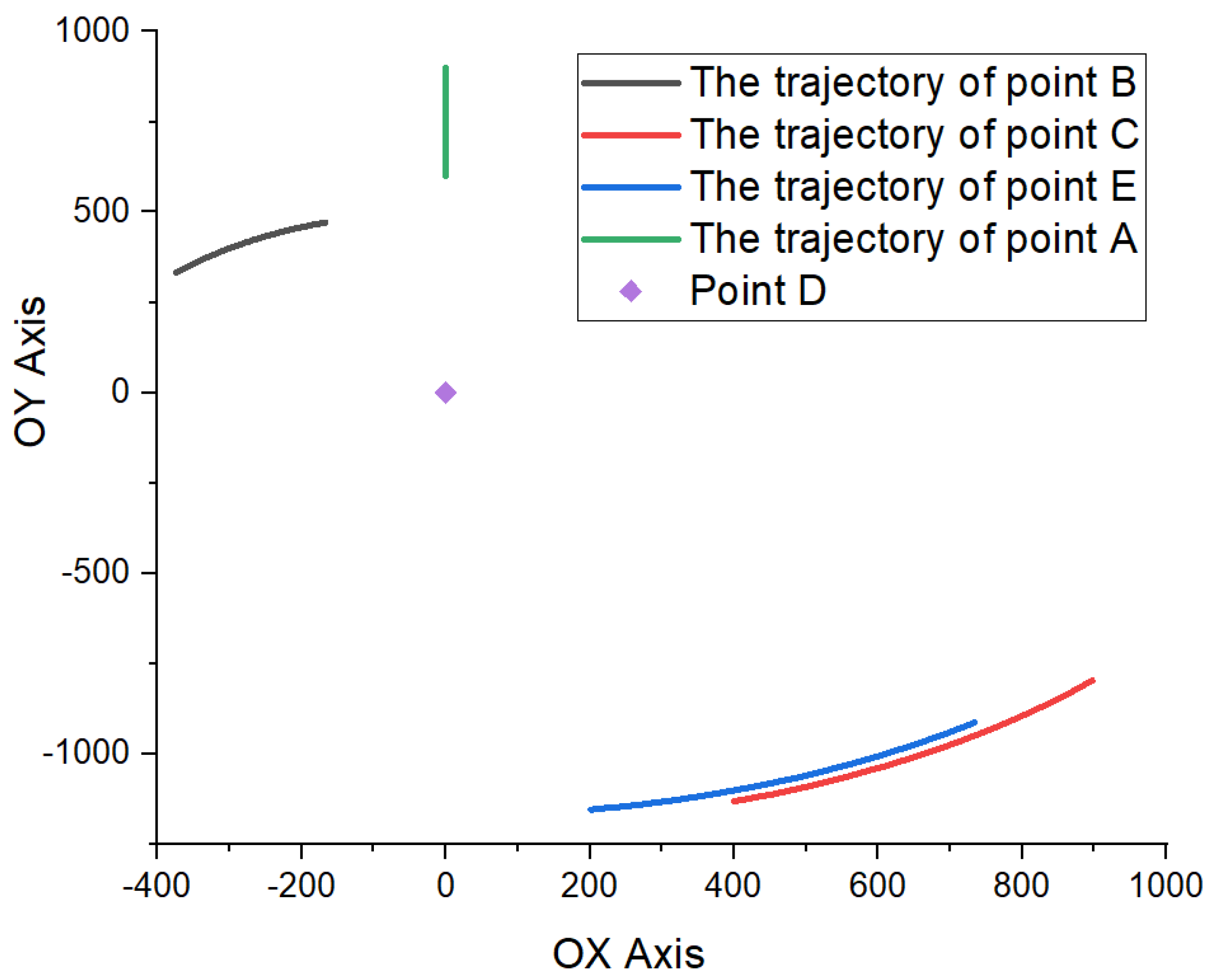
- The distance is d = 900 mm, although the displacement of coupling A moved in the range of 600–900 mm over a distance of 300 mm;
- -
- The coordinates of coupling D are (0,0);
- -
- Value of element AB = 460 mm (noted by a in Figure 3);
- -
- Value of element BC = 1700 mm (noted by b in Figure 3);
- -
- Value of element BD = 500 mm (noted by e in Figure 3);
- -
- Value of element CE = 200 mm (noted by c in Figure 3);
- -
- Value of angle θ = 77° (the angle generated by elements BC and CE, as shown in Figure 3).
- -
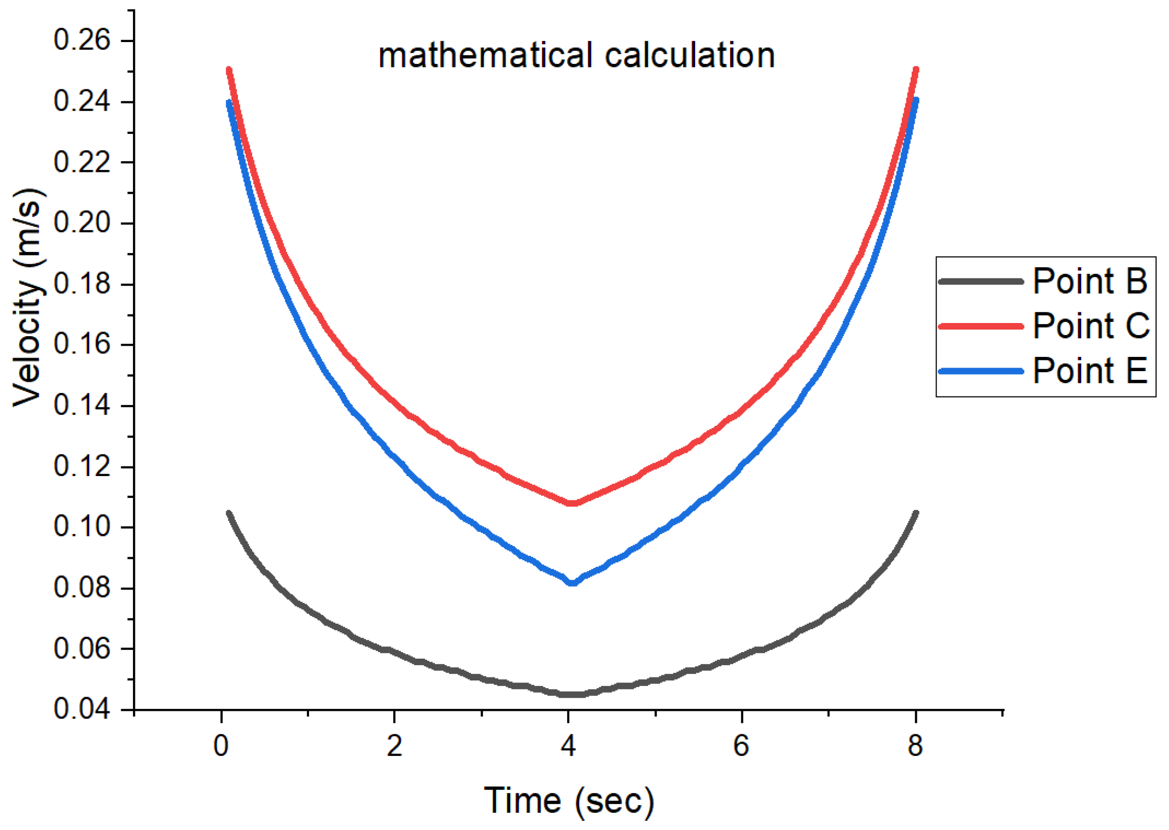
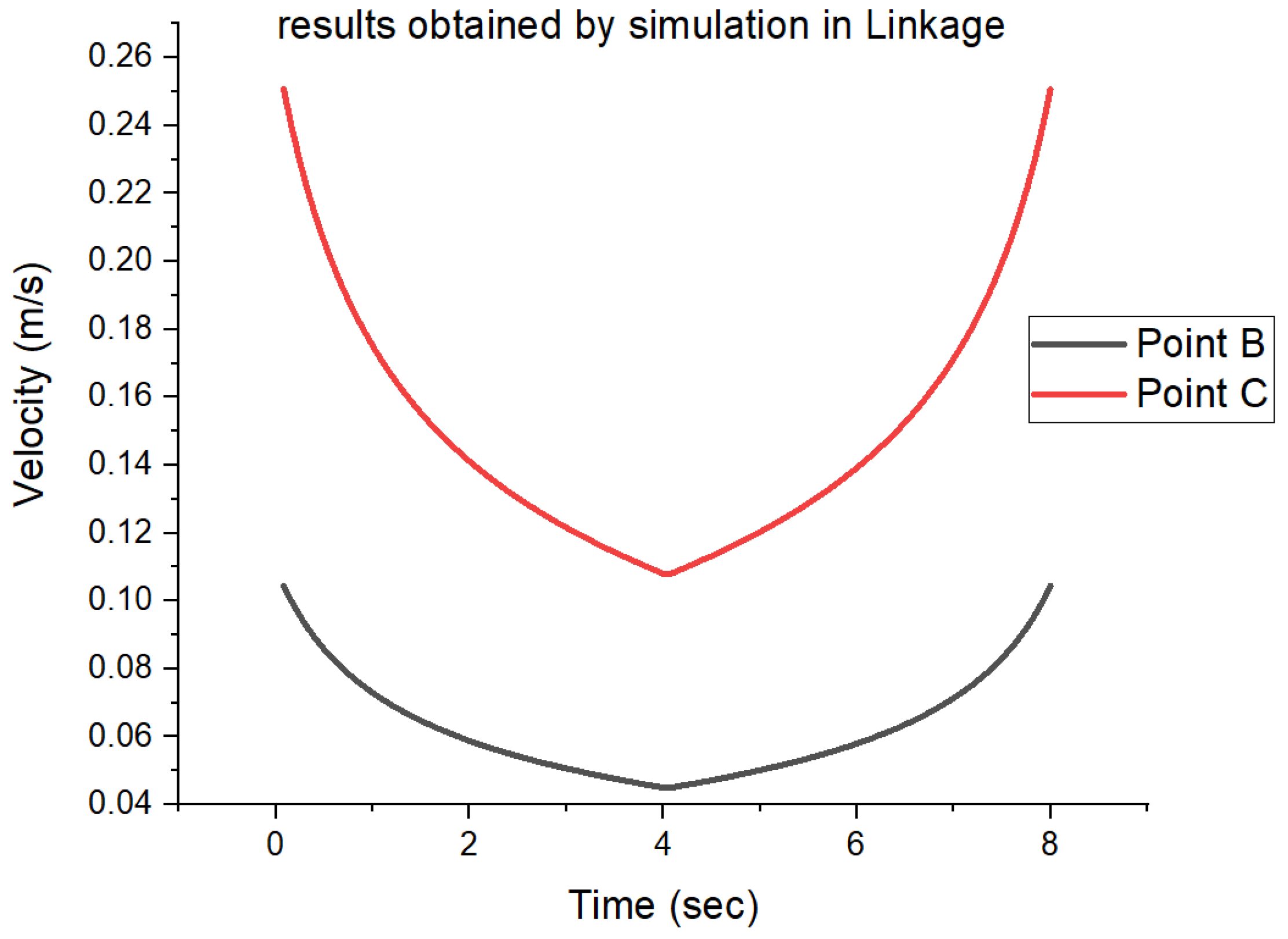
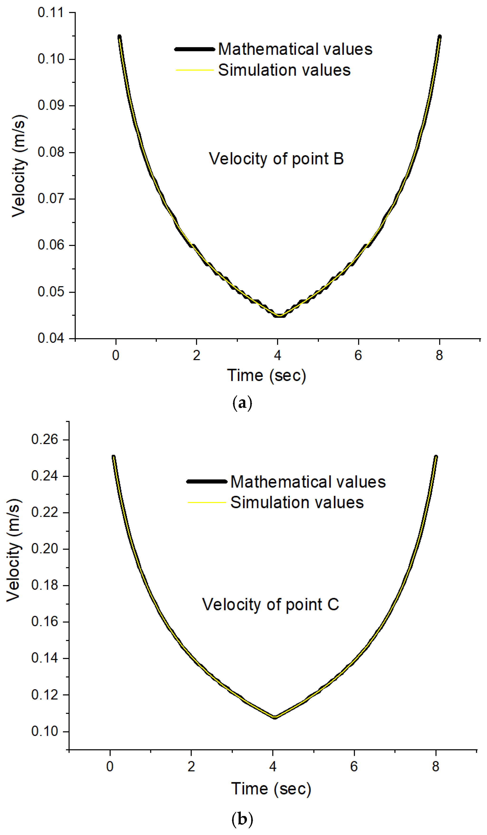
- Regardless of which point is subject to the analysis (B, C, or E), variations in linear velocity have the shape of a parabola, with its depth closely related to the position of the point in relation to the vertical axis (at the maximum tightening position of the mechanism).
- -
- The highest value of the linear velocity was obtained for coupling C and is 0.25 m/s while the lowest value was obtained for coupling B and is 0.04 m/s.
- -
- By analyzing each coupling, the following observations were found:
- ○
- For coupling B, the difference between the minimum and maximum value of the studied parameter is 0.07 m/s.
- ○
- The maximum speed of 0.25 m/s corresponding to the displacement of coupling C is obtained when the distance between points A and D is at the maximum, and the lowest value of 0.11 m/s is obtained when the distance between points A and D is at the minimum.
- ○
- As for the variation in the linear velocity of point E, it shows the same variation as for coupling C, but the minimum value is 0.08 m/s and the maximum value is 0.24 m/s.
- -
- point A is positioned on the fixed element GD, thus being transported in the translation coupling;
- -
- the fixed element GD is parallel to the axis OY. Thus, the movement that point A must realize is respected;
- -
- a hydraulic piston was used to move point A at constant speed (it connects points A and G).
4. Conclusions
- -
- Both linear velocity variations were parabolic.
- -
- Both linear speed variations had a minimum point that occurred at the time of 4 sec (this time corresponds to moving point A from 900 mm to 600 mm).
Author Contributions
Funding
Institutional Review Board Statement
Informed Consent Statement
Data Availability Statement
Conflicts of Interest
References
- Crudu, S.D. Particular cases for the constructive optimization of the lifting arm from the frontal loader working equipment. Acta Technol. Napoc. Ser. 2022, 65, 229–234. [Google Scholar]
- Dan, S.Y. Lifting system equipment eesign of vertical shaft extended excavation in Shiyashan tunnel. In Proceedings of the 16th International Symposium on Advancement of Construction Management and Real Estate, Hong Kong, China, 23–25 September 2011; pp. 161–165. [Google Scholar]
- Stastny, J.; Motycka, V. Design optimization of lifting mechanisms. In Proceedings of the 3rd World Multidisciplinary Civil Engineering, Architecture, Urban Planning Symposium (Wmcaus 2018), Prague, Czech Republic, 18–22 June 2019; Volume 471, pp. 1–9. [Google Scholar]
- Sun, A.P.; Jia, H.W.; Ma, Y.P. Tower equipment lifting crane and tools selection and optimization. Manuf. Process Equip. 2013, 694–697, 2978–2982. [Google Scholar] [CrossRef]
- Xiao, W.S.; Li, C.J.; Fan, L.H.; Li, Q.; Tan, L.P. Dynamic analysis of the lifting arm system in the integrated offshore platform decommissioning equipment in complicated sea states. Processes 2023, 11, 645. [Google Scholar] [CrossRef]
- Mitchell, P.E. Tool and Manufacturing Engineers Handbook; Society of Manufacturing Engineers, One SME Drive: Dearborn, MI, USA, 1998. [Google Scholar]
- Siddhartha, R. Introduction to Materials Hangling; New Age International (P) Limited, Publishers, Daryaganj: New Delhi, India, 2008. [Google Scholar]
- Kulka, J.; Mantic, M.; Kopas, M.; Faltinová, E. Assessing the need for rope replacement in crane lifting equipment after change of crane operational parameters. Adv. Sci. Technol.-Res. 2017, 11, 226–230. [Google Scholar] [CrossRef][Green Version]
- Baisan, I. Transport Operațional în Agricultură și Industria Alimentară; Universitatea Tehnică Gh. Asachi din Iași Facultatea de Mecanică: Iași, Romania, 2016. [Google Scholar]
- Jascanu, M. Echipamente de Transport în Industria Alimentară; Editura Fundaţiei Universitare “Dunărea de Jos”: Galaţi, Romania, 2004. [Google Scholar]
- Wharton. Material Handling 2015; Wharton Hardware & Supply Co., Inc.: Pennsauken Township, NJ, USA, 2015. [Google Scholar]
- Amosov, A.G.; Rozhdestvensky, O.K. Influence of chemical composition of lifting equipment material on their performance. Int. J. Integr. Eng. 2023, 15, 42–50. [Google Scholar] [CrossRef]
- Du, M.Q.; Yang, X.Q.; He, W.; Zhao, D.F. Mechanism design and simulation analysis of a new baggage diversion lifting mechanism. In Proceedings of the 6th International Conference on Control, Mechatronics and Automation, Tokyo, Japan, 12–14 October 2018; pp. 92–96. [Google Scholar]
- Hong, T.D.; Pham, M.Q.; Tran, S.C.; Tran, L.Q.; Nguyen, T.T. A comparative study on kinetics and dynamics of two dump truck lifting mechanisms using MATLAB Simscape. Theor. Appl. Mech. Lett. 2024, 14, 100502. [Google Scholar] [CrossRef]
- Kitaeva, M.V.; ANikolaev, Y.; Taranov, A.V.; Mehtiev, A.D. Studying mathematical model of mine and quarry pneumatic lifting equipment in “skip guidance devices” systems. Int. Sci. Conf. Radiat.-Therm. Eff. Process. Inorg. Mater. 2015, 81, 1–12. [Google Scholar] [CrossRef]
- Veselovska, N.; Shargorodskyi, S.; Rutkevych, V.; Kupchuk, I.; Burlaka, S. Development of the mathematical model of the hydraulic drive of the lift mechanism of the working equipment of the front loader. Prz. Elektrotechniczn. 2023, 99, 34–38. [Google Scholar] [CrossRef]
- Kay Michael, G. Material Handling Equipment; North Carolina State University: Raleigh, NC, USA, 2012. [Google Scholar]
- Zubilov, G.; Litvinov, P.; Mel’nikov, V.; Sorokin, A.; Zhukov, S. Hydraulic drive boom lifting mechanism. In Proceedings of the International Workshop Advanced Technologies in Material Science, Mechanical and Automation Engineering–Mip: Engineering, Krasnoyarsk, Russia, 4–6 April 2019; Volume 537, pp. 1–8. [Google Scholar]
- Abdrakhimov, U.T.; Akimkhanova, A.A. Kinetostatic calculation of a high class lifting mechanism (by assur classification) of a technological load-lifting machine. J. Math. Mech. Comput. S 2023, 118, 57–63. [Google Scholar] [CrossRef]
- Ablyazov, E.K.; Ablyazov, K.A. Assessment of the technical condition of the port lifting and transport equipment (LTE) using fuzzy logic. Mar. Intellect. Technol. 2024, 1, 242–251. [Google Scholar]
- Andziulis, A.; Eglynas, T.; Bogdevicius, M.; Jusis, M.; Senulis, A. Multibody dynamic simulation and transient analysis of quay crane spreader and lifting mechanism. Adv. Mech. Eng. 2016, 8, 1–11. [Google Scholar] [CrossRef]
- Faltinová, E.; Mantic, M.; Kul’ka, J.; Kopas, M. Reliability analysis of crane lifting mechanism. Sci. J. Sil. Univ. Technol. 2018, 98, 15–26. [Google Scholar] [CrossRef]
- Javorskyj, I.M.; Yuzefovych, R.M.; Lychak, O.V.; Semenov, P.O.; Varyvoda, M.Z. Vibration analysis of the damaged bearing unit of the port crane lifting mechanism. Mater. Sci. 2024, 59, 395–404. [Google Scholar] [CrossRef]
- Seidakhmet, A.; Tuleshov, A.; Jamalov, N.; Jomartov, A.; Cieslik, J.; Abduraimov, A.; Kamal, A.; Kaliyev, M.; Bissembayev, K. Research of kinematics and dynamics of the lever lifting mechanism used in the mobile automotive lift. Appl. Sci. 2023, 13, 11361. [Google Scholar] [CrossRef]
- Zhang, Y.N.; Huang, Q.B.; Cui, Y.Z. Modeling and simulation of virtual prototype of the lift-sliding mechanical parking equipment based on solid works. In Proceedings of the International Conference on Modeling, Simulation and Optimization, Proceedings, Bali, Indonesia, 25–29 May 2009; pp. 232–235. [Google Scholar]
- Zhang, Z. High-precision angle adaptive control simulation of synchronous motor for automatic lifting and boarding equipment of aircraft platform. Sci. Rep. 2023, 13, 1–11. [Google Scholar] [CrossRef]
- Zheng, X.Z.; Xiao, L.; Zhang, G.F. Study on the safety of large lifting equipment installation base on fuzzy synthesized assessment method. Manag. Eng. Appl. 2010, 110–116. [Google Scholar]
- Mosnegutu, E.; Barsan, N.; Panainte-Lehadus, M.; Chitimus, D.; Tomozei, C. Influence of the crank mechanism position in the motion of an oscillating sieve. J. Eng. Stud. Res. 2021, 27, 36–43. [Google Scholar] [CrossRef]
- Mosnegutu, E.; Tomozei, C.; Panainte-Lehadus, M.; Chitimus, D.; Irimia, O. Geometric calculation of the influence of an oscillating sieve’s actuation mechanism position on its motion. Processes 2022, 10, 1760. [Google Scholar] [CrossRef]
- Bourgeois, A.; Rice, B.; Goh, C.H. Design optimization of the lift mechanism in the robotic walking training device using the engineering design methodology. Appl. Sci. 2024, 14, 327. [Google Scholar] [CrossRef]
- Chang, C.Y.; Hung, Y.C.; Chen, W.L.; Huang, Y. Mechanism optimization of the clamping and cutting arrangement device for solanaceae scion and stock seedlings. Appl. Sci. 2023, 13, 1548. [Google Scholar] [CrossRef]
- Chang, W.T.; Lee, W.I.; Hsu, K.L. Analysis and experimental verification of mechanical errors in nine-link type double-toggle mold/die clamping mechanisms. Appl. Sci. 2021, 11, 832. [Google Scholar] [CrossRef]
- Gu, Y.F.; Xing, J.C. Dynamics analysis for the clamping mechanisms of a rotary inchworm piezoelectric motor. J. Vibroeng. 2016, 18, 2229–2239. [Google Scholar] [CrossRef]
- Jin, Z.M.; Zhang, Y.J.; Wang, X.L.; Williams, J.; Liu, Z.; Huang, Z.Y.; Falkner, D.; Zhou, G.; Dong, L.Q.; Zhuang, J.; et al. Microstructure of injection moulding machine mould clamping mechanism: Design and motion simulation. CAAI Trans. Intell. Technol. 2017, 2, 101–108. [Google Scholar] [CrossRef]
- Lee, T.E.; Lee, R.M.; Liu, P.T. Design and production of toilet seat lifting mechanism. Int. Conf. Comput. Precis. Eng. 2016, 71, 1–7. [Google Scholar] [CrossRef]
- Li, W.H.; Kang, F. Design and analysis of steering and lifting mechanisms for forestry vehicle chassis. Math. Probl. Eng. 2020, 2020, 1–16. [Google Scholar] [CrossRef]
- Talaska, Z.; Jakus, B. Modernisation of a lift that constitutes part of the breathing simulator, equipment part 2. Pol. Hyperb. Res. 2019, 68, 7–31. [Google Scholar] [CrossRef]
- Verenski, D.R.; Suchora, D.H.; Allen, C.W. Experimental and finite element analysis of tong load slip versus clamping force. In Proceedings of the ASME 2010 International Mechanical Engineering Congress and Exposition, 12–18 November 2010; pp. 699–707. [Google Scholar]
- Hsu, Y.L.; Fung, R.F. Mathematical modelling and two-stage identification for a motor-toggle mechanism with clamping effect. Appl. Math. Model 2016, 40, 8660–8670. [Google Scholar] [CrossRef]
- Prydalnyi, B. Mathematical model of a backlash elimination in the new clamping mechanism. In Advanced Manufacturing Processes III; Springer International Publishing: Berlin/Heidelberg, Germany, 2022; pp. 109–118. [Google Scholar]
- Feng, Y.; Wu, S.L.; Nie, H.L.; Peng, C.C.; Wang, W. Simulation and mechanism analysis of fretting wear of parallel groove clamps in distribution networks caused by Karman vortex vibration. Ind. Lubr. Tribol. 2024, 76, 1108–1116. [Google Scholar] [CrossRef]
- Luo, K.; Bai, Y.; Jin, T.; Qiu, K.Z.; Fan, J.R. Direct numerical simulation study on the stabilization mechanism of a turbulent lifted pulverized coal jet flame in a heated coflow. Energy Fuel 2017, 31, 8742–8757. [Google Scholar] [CrossRef]
- Song, B.; Wang, H.; Cui, W.H.; Zhang, J.B.; Liu, H. Dynamic simulation and optimization of clamping mechanism of online tension testing machine for wire ropes. Eng. Fail Anal. 2019, 95, 181–190. [Google Scholar] [CrossRef]
- Zhang, W.; Zhang, X.F.; Yan, C.; Xiang, S.J.; Wang, L.W. A characteristic triangle method on input vectors of scissor lift mechanism and its applications in modeling and analysis. J. Adv. Mech. Des. Syst. 2015, 9, 1–20. [Google Scholar] [CrossRef]
- Zhai, F.G.; He, Z.Q.; Zhao, Y.F.; Yang, L.; Kong, X.D. Control methodology of synchronous lifting for the dual forging manipulator at clamping condition. Sci. Rep. 2022, 12, 1–12. [Google Scholar] [CrossRef]
- Zhang, J.; Wai, R.O. Novel space-vector pulse-width-modulation mechanism for three-level neutral-point-clamped z-source inverter. In Proceedings of the 2019 4th International Conference on Intelligent Green Building and Smart Grid, Yichang, China, 9 June 2019; pp. 5–9. [Google Scholar]
- Song, R.; He, Y.; Li, Z.; Yu, Y.; Li, Y.W.; Xu, C.S. Blood orange clamping damage mechanism based on finite element method. J. Food Meas. Charact. 2025, 19, 453–466. [Google Scholar] [CrossRef]
- Rashid, H.; Ariffin, M.K.A.M.; Noh, M.H.M.; Abdullah, A.H.; Hamid, A.H.A.; Jusoh, M.A.M.; Othman, A. Design review of scissors lifts structure for commercial aircraft ground support equipment using finite element analysis. Int. Symp. Robot. Intell. Sens. 2012, 41, 1696–1701. [Google Scholar] [CrossRef][Green Version]
- Model ST—Slab Tongs. Available online: https://www.fsindustries.com/more_info/model_71_slab_tongs/model_71_slab_tongs.shtml (accessed on 12 June 2024).
- Lifting Tongs. Available online: http://liftmax.com/specialty-lifters/lifting-tongs.htm (accessed on 12 June 2024).
- Rahul, M.; Nataraj, J.R. Kinematic design methodology of vertical coil tong. Int. Res. J. Eng. Technol. 2019, 6, 2769–2775. [Google Scholar]
- Mathcad 15. Available online: https://www.mathcad.com/en (accessed on 12 June 2024).
- Rector, D.M. Linkage Mechanism Designer and Simulator. Available online: https://blog.rectorsquid.com/linkage-mechanism-designer-and-simulator/ (accessed on 12 June 2024).
- OriginPro 2019b, Version 9.6.5.169. Available online: https://www.originlab.com/ (accessed on 13 June 2024).

Disclaimer/Publisher’s Note: The statements, opinions and data contained in all publications are solely those of the individual author(s) and contributor(s) and not of MDPI and/or the editor(s). MDPI and/or the editor(s) disclaim responsibility for any injury to people or property resulting from any ideas, methods, instructions or products referred to in the content. |
© 2025 by the authors. Licensee MDPI, Basel, Switzerland. This article is an open access article distributed under the terms and conditions of the Creative Commons Attribution (CC BY) license (https://creativecommons.org/licenses/by/4.0/).
Share and Cite
Moșneguțu, E.; Jasiński, M.; Panainte-Lehăduș, M.; Tomozei, C.; Irimia, O.; Sporea, N.; Bibire, L.; Wiewiórska, I. Mathematical Study of a Product-Gripping Mechanism for Industrial Transportation. Appl. Sci. 2025, 15, 4176. https://doi.org/10.3390/app15084176
Moșneguțu E, Jasiński M, Panainte-Lehăduș M, Tomozei C, Irimia O, Sporea N, Bibire L, Wiewiórska I. Mathematical Study of a Product-Gripping Mechanism for Industrial Transportation. Applied Sciences. 2025; 15(8):4176. https://doi.org/10.3390/app15084176
Chicago/Turabian StyleMoșneguțu, Emilian, Marcin Jasiński, Mirela Panainte-Lehăduș, Claudia Tomozei, Oana Irimia, Nicoleta Sporea, Luminita Bibire, and Iwona Wiewiórska. 2025. "Mathematical Study of a Product-Gripping Mechanism for Industrial Transportation" Applied Sciences 15, no. 8: 4176. https://doi.org/10.3390/app15084176
APA StyleMoșneguțu, E., Jasiński, M., Panainte-Lehăduș, M., Tomozei, C., Irimia, O., Sporea, N., Bibire, L., & Wiewiórska, I. (2025). Mathematical Study of a Product-Gripping Mechanism for Industrial Transportation. Applied Sciences, 15(8), 4176. https://doi.org/10.3390/app15084176


