1. Introduction
Finding cost-effective and equitable healthcare solutions is a fundamental objective of sustainable medicine, and Additive Manufacturing (AM) technology (also colloquially named 3D Printing) can contribute to this goal by enabling the production of personalized medical devices at lower costs while also facilitating the decentralized manufacturing across different regions [
1]. The external fixators (EFs) are among the medical devices for which cost remains an important concern, particularly in low-income regions [
2], while their availability in conflict zones and disaster relief settings further underlines the need for more accessible and adaptable solutions [
3,
4,
5].
EFs are used for stabilizing fractures and treating congenital deformities, malformations, dislocations, contractures, and dysplasia [
6]. Their mechanical performance depends on the EF–bone stiffness, healing stage, and load-bearing demands. Excessive stress or micro-strains can delay the healing by promoting fibrous tissue over stable callus formation [
7,
8,
9,
10,
11], while excessive rigidity may inhibit interfragmentary movements (IFMs), critical for early callus development, especially for fracture gaps over 1 mm [
11]. Compared to internal fixation, EFs allow for a closed fracture reduction with minimal vascular disruption and enable real-time monitoring via imaging, making MRI compatibility an important design factor [
7,
12]. However, EFs also pose challenges, including their structural complexity, need for surgical expertise, and risks like pin loosening, mechanical failure, delayed union, vascular injury, and infection at anchoring sites, these requiring careful monitoring [
7].
As mentioned, cost is another major challenge, with temporary fixators around
$5892 per frame, and definitive fixation around
$6013 [
13]. Given the high incidence of traumatic injuries in low- and middle-income countries, more affordable alternatives are required. Cinthuja et al. [
4] highlighted the importance of locally producing EFs, and, in this context, AM can be a promising alternative. By supporting decentralized manufacturing, AM aligns with the 3D-Printing Point-of-Care concept [
14], which enhances EF availability in resource-limited settings, war zones, and even outer space.
The use of 3D-printed EF components, especially rings and clamps, is still emerging, with limited studies available in the literature. A review by O’Connor et al. [
15] identified only nine studies, four of which addressed tibial fractures. Designs included circumferential frames such as the Q-fixator by Qiao et al. [
16] and Wu et al.’s contouring shell [
17], and unilateral bars for distal radius fractures [
18]. Due to the low stiffness of materials like PLA, ABS, and Onyx, these studies often propose bulkier geometries for compensation. Some research focused on 3D-printed clamps, such as Landaeta et al. [
19], who proposed an Onyx clamp tested per ASTM F1541 [
20], showing performance comparable to commercial versions.
Building on these efforts, this study proposes a cost-effective alternative to conventional EF rings using 3D-printed PLA-CF. The focus is on hybrid fixators, less studied than linear or Ilizarov EF’s types [
9]. A finite element analysis (FEA) evaluates the mechanical feasibility of this solution, aiming for a balance between strength and weight. FEA was widely applied in EF studies to optimize the design parameters and assess the mechanical stability under different loading conditions, including axial compression, bending, and torsion [
21,
22,
23,
24,
25,
26]. Aziz et al. examined Ilizarov, unilateral, and hybrid fixators for femoral fractures, showing that, while unilateral fixators provide greater stability, they may not offer adequate support for complex fractures [
21]. Wahab et al. showed that a double-cross tibial EF configuration offers superior biomechanical stability [
11], while Ramlee et al. found that the Delta fixator provides better stability for pilon fractures [
22].
One of the key challenges in EF modeling is achieving an optimal balance between stiffness and flexibility. Increased stiffness improves stability, but may hinder bone healing by restricting IFMs. Factors like pin diameter, placement, and number also play a crucial role. Sternick et al. proved that larger pin diameters improve rigidity [
23], but cause complications such as excessive stress at the pin–bone interface, resulting in loosening or infection. Ramlee et al. optimized the pin diameter selection and found that a value of 5.5 mm provides the best compromise between stiffness and stress distribution [
24].
Computational methods like genetic algorithms [
25] and Taguchi-ANOVA [
26] have been used for geometrical optimization, reducing simulations by over 500 times. These studies identified rod elevation (i.e., the distance between the fixator rod and the bone) as the most influential factor on stability—lowering it reduces IFM strain and accelerates recovery.
While conventional EF designs are well-studied, only one work [
27] proposed a cost-effective alternative to Ilizarov rings, using a glass-fiber-reinforced composite ring validated through FEM and standard testing.
Clinically, hybrid EFs have shown advantages such as earlier weight-bearing and an improved range of motion, but they are not studied by numerical means [
28]. Moreover, just a few numerical studies incorporate callus formation as a time-dependent variable. Zhao et al. monitored strain evolution in bone and fixators in different healing stages [
29], while Li et al. identified three stiffness evolution phases [
30]: an early stage (0–5 weeks) where the fixator bears most of the load, an intermediate stage (5–12 weeks) where increasing the callus stiffness gradually transfers load to the bone, and a late stage (12–15 weeks) where the bone fully supports the load, reducing reliance on the fixator.
A literature review showed that hybrid fixators with 3D-printed polymeric composite rings are largely unexplored. This study addresses this gap by investigating the feasibility of printing short carbon-fiber-reinforced polylactic acid (PLA-CF) rings, integrating pre-stressed fixation wires, and analyzing their mechanical behavior across healing stages. A novel contribution is the inclusion of pre-stressing in the wires, rarely considered in simulations, which improves biomechanical assessment accuracy. Mechanical performance is evaluated at two important orthopedic milestones: the initial fracture gap and early weight-bearing (day 1 to week 4), with a focus on tibial fractures, one of the most commonly injured long bones [
31].
2. Materials and Methods
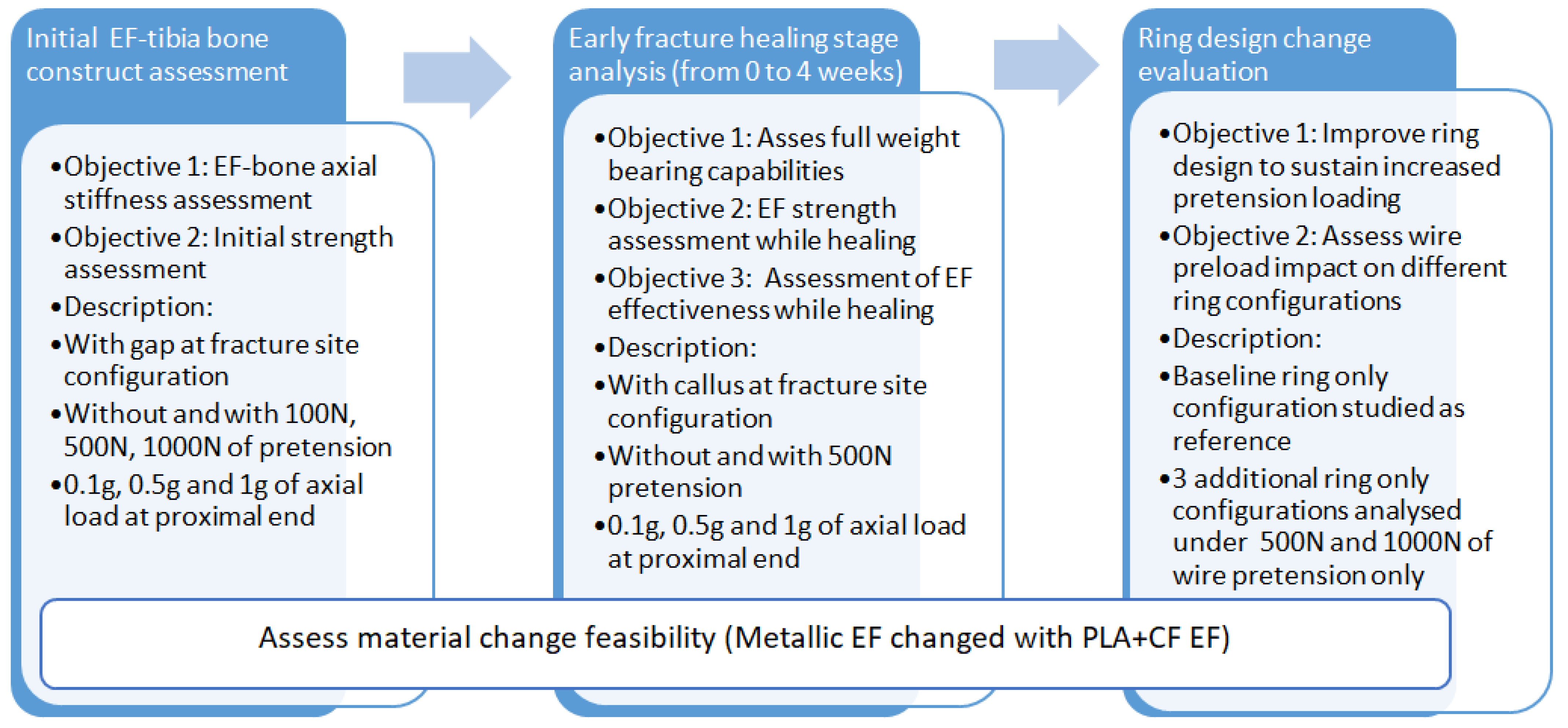
This study follows a structured methodology for evaluating the feasibility of replacing stainless-steel EFs with PLA-CF alternatives, as presented in
Figure 1. The approach consists of three main phases:
- 1.
Initial EF–tibia bone design assessment—evaluates the axial stiffness and initial strength under varying loading conditions (0.1 g, 0.5 g, and 1 g, where g is the gravitational force equivalent for a 70 kg male expressed in N) and wire pre-tension levels (100 N, 500 N, and 1000 N). The analysis includes a fracture gap configuration to assess structural stability;
- 2.
Early fracture healing stage analysis (0–4 weeks)—investigates EF strength and weight-bearing capacity with progressive callus formation. The model includes simulations with and without 500 N wire pre-tension to assess the impact of healing on EF–bone stability;
- 3.
Ring design change evaluation—optimizes EF ring configurations for sustaining higher pre-tension loads. A baseline ring is compared with three alternative designs under wire pre-tension of 500 N and 1000 N, to enhance stiffness and load distribution.
2.1. Theoretical Considerations
The designing and analysis of hybrid EFs involves several mechanical and biomechanical considerations, including material properties, load distribution, and stress analysis.
Based on the principle of force equilibrium and stiffness, when an axial load is applied to a system consisting of a bone and a fixator, the applied forces are distributed between the two bodies. The resulting total load must be conserved. Thus, the sum of the forces acting in the bone and the fixator must equal the applied load:
where
Fapplied describes the total axial load applied to the system,
Fbone represents the axial force transferred by the bone, and
Ffixator the axial force transferred by the fixator.
In the initial healing phase, the stiffness of the bone is assumed to be negligible. Thus, the entire load is transferred via the fixator. The load carried by the fixator will be equal to the total applied load:
As callus formation progresses, the stiffness of the bone increases gradually. This stiffness contributes to the overall system as a part of the load distribution. The bone and the fixator share the load, and the load on each component depends on the relative stiffness of the bone, callus area, and the fixator.
The load is transferred inversely proportionally to the stiffness. In a simplified form, the length is not considered explicitly, assuming both the bone and fixator have enough length to allow their respective stiffness to contribute meaningfully to the overall load sharing. Thus, the element with higher stiffness will carry more of the total load.
The stiffness of the system can be evaluated by using the following relations:
The total stiffness of the system, assuming the bone and fixator are acting in parallel, is the stiffness sum of the individual elements:
The load carried by each component is proportional to the stiffness of the component relative to the total stiffness. Hence, the force on the fixator is proportional to the stiffness of the fixator relative to the total stiffness:
Substituting for stiffness, equation 1 provides a generic overview of how the axial loads are transferred from the bone to the fixator system:
Pre-tensioning the wires constrains the initial compressive force at the fracture site. This ensures the required stability by minimizing the micromotion during the early healing phase. Compressive loads alter the fixator stiffness by increasing its resistance to external forces. As the bone heals and its stiffness increases, the load is gradually shared more evenly between the bone and the fixator. This critical design consideration can be estimated by taking into account the elastic deformation of the wires:
where Δ
L represents the elongation of the wire,
Ftension is the pre-tensioning force applied to the wire, and
Ewire the modulus of elasticity of the wire material. However, the bending of the EF ring due to the out-of-plane loads influences the stress experienced by the wires. Depending on the fixator configuration, the wires behave similarly to a cantilevered beam or a simply supported beam, experiencing both deflections and rotations. Thus, the tensile stresses are most relevant for evaluating their structural integrity. The calculated values are compared to the tensile yield strength of the material.
By referencing equation 7, the equilibrium between
Ffixator and
Fapplied is ensured by the load paths which occur due the geometry of the load-bearing components. Furthermore, this equilibrium is highly influenced by the pre-tensioning of the wires. Thus, the resulting combination of axial, bending, and shear stresses requires the evaluation of the von Mises (VM) stress. The safety factor of the structure can be evaluated as follows:
where
nVM represents the VM safety factor and
σVM the VM stress.
The von Mises criterion is employed for cancellous bone, callus, and the external fixator components because these materials experience multiaxial stresses and are better characterized by the combined effects of axial, shear, and bending stresses, which the von Mises criterion effectively accounts for.
As a reference, the recommended safety factor range for medical devices is 1.3–2.5 to ensure structural reliability and cost-efficiency [
32].
In case of dominant shear loading or when the geometry includes sharp corners or notches, the Tresca failure criterion is more conservative. In this case, failure occurs when
τmax reaches 0.5
σy:
where
σ1 and
σ3 represent principal stresses.
The Tresca criterion is applied to cortical bone due to its susceptibility to fail under shear stress gradients, especially in the proximity of the wire junction areas.
2.2. EF–Bone Modeling
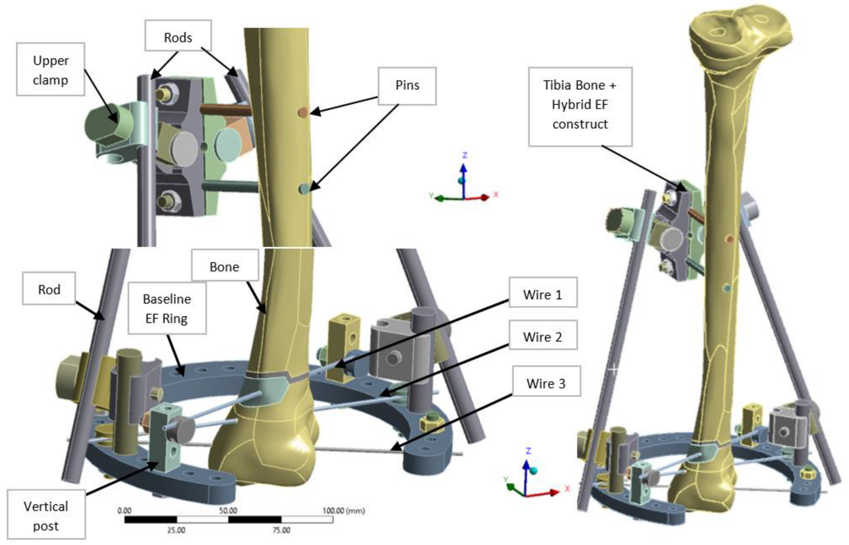
A hybrid EF, combining elements of both linear and radial fixators, was designed in CATIA V5R21 (Dassault Systemes, Fr) to provide enhanced adjustability and load distribution, particularly for tibial and pilon fractures (
Figure 2). The EF was based on TL-EVO design (Orthofix Orthopedics [
33]), and integrates a partial 5/8 ring (arch) bridge element at the lower end, connected by to two longitudinal rods linked with clamps. Three tension wires (Kirschner wires or K-wires) are fixed at the ring level and pass through the tibia lower side for stabilization. Two cortical pins or screws are used as additional anchoring points at the upper part of the fixator, secured with modular clamps. The diameter of the ring located at distal tibia end is 160 mm (140 mm in inner and 180 mm in outer side) with 10 mm of thickness, and include 28 open hole of 6 mm diameter, evenly distributed at 10°. The K-wires (denoted wire 1–3) that connect the ring to the bone have a diameter of 1.8 mm and are installed respecting the safe passage corridors of the distal tibia end (areas with minimal tissue coverage and no nerves), while the longitudinal rods linking the ring to the upper clamp and the pins anchoring the EF to the middle tibia shaft measure 9 mm and 6 mm in diameter, respectively. The two parallel pins are located at 30 mm distance to tibia surface and are spaced with 40 mm between them as presented in
Figure 2.
The bone geometry was obtained from computed tomography (CT) scans of a healthy male patient for ensuring real shape and dimensions. Mimics 10 (Materialse, Be) was used for CT medical reconstruction, and CATIA V5 (Dassult Systemes, Fr) for obtaining the 3D CAD solid model of the bone, with the raw geometry cleaned and prepared for FEA. This step was time-consuming and labor-intensive but essential in order to ensure a high-quality mesh and the precise application of boundary conditions.
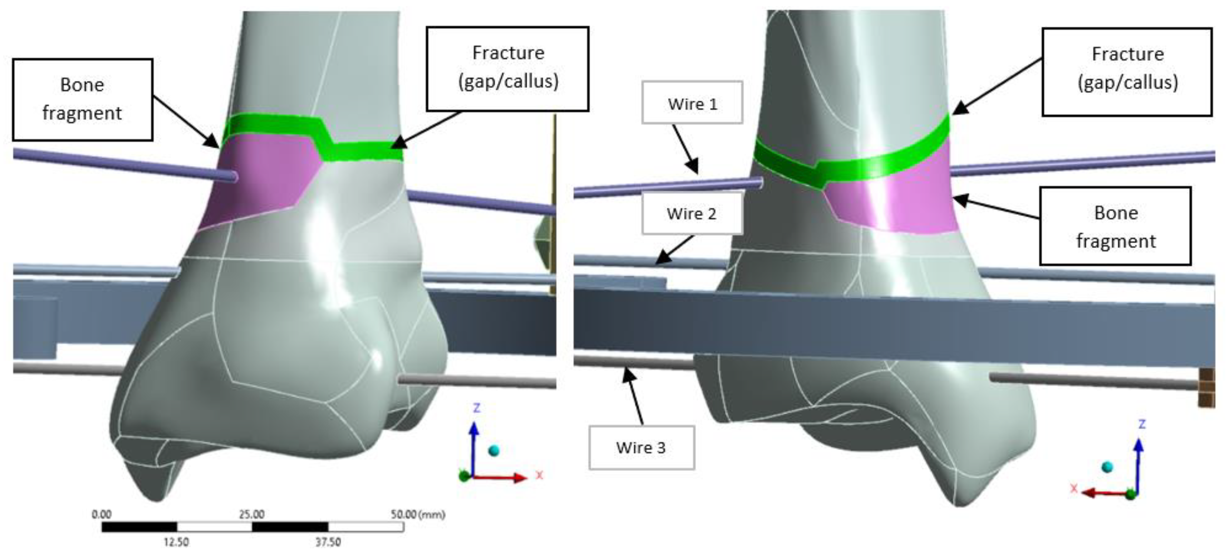
A distal extra-articular fracture classified as 43-A2 under the AO system was selected for analysis, incorporating a 3 mm fracture gap to simulate callus formation during healing. The model was developed in ANSYS 19.0 (ANSYS, Inc., Canonsburg, PA, USA), with the fracture fragment highlighted in magenta and the fracture line in green (
Figure 3).
To ensure proper alignment and stabilization of the bone fragments during healing, three pre-tensioned K-wires are used. Wire 1 is positioned diagonally on vertical posts, with a Z-offset from the ring axis of 30 mm on one side and 17.5 mm on the other, allowing precise alignment and fixation of the bone fragment, as shown in
Figure 3. Once the desired tension is applied, wire tensioning clamps secure the wires in place, maintaining stability throughout the healing process.
2.3. Materials Properties
In this study, a conservative approach was adopted [
34], where the diaphysis was modeled as cortical bone, and epiphyses as cancellous bone, and medullary cavity was considered empty (its absence did not significantly affect the bone stress results, as shown by Tarapoom et al. [
34]). The cortical shear bone strength from [
35] was compared with the Tresca stresses, which was found to be more conservative than comparing tension/compression strength to maximum and minimum principal stresses. Additionally, the properties of the callus in different developmental stages were derived from the literature (
Table 1), with the elastic modulus and Poisson’s ratio adopted from [
29], and the yield strength from [
36].
Regarding the 3D-printed EF ring, in FEM calculation, isotropic PLA-CF properties of the rings were considered (
Table 1). Although 3D-printed polymers usually exhibit anisotropic behavior due to the layer-by-layer deposition process and infill structure, the use of a gyroid pattern at 100% infill density justifies this simplification. Experimental and numerical studies showed that gyroid infills present near-isotropic behavior [
37], ensuring similar strength and resistance in all directions, which is not the case, for instance, with grids or honeycombs patterns.
Table 1.
Materials and mechanical properties for FEA.
Table 1.
Materials and mechanical properties for FEA.
| Material | Tensile Ultimate Strength [MPa] | Tensile Yield
Strength [MPa] | Tensile Modulus [MPa] | Poisson Ratio [-] | Failure Criteria (4) |
|---|
| Kirschner Wires—Stainless Steel 316LVM [38] | 1100 | 800 | 187,500 (5) | 0.33 (5) | Normal Stress |
| Cortical Bone [35] | 135 (Tension)
205 (Compression)
65 (Shear) | 71.5 (Tension)
115 (Compression)
41 (Shear) | 16,000 | 0.3 | Tresca |
| Cancellous Bone | - | 16.3 (1) | 1100 | 0.26 |
Callus
[29,36] | Granulation Tissue
Initial—0 weeks | - | 0.5 (2) | 1 | 0.167 | VM |
Fibrous Tissue
0.4 weeks | - | 2.8 (2) | 5 | 0.167 |
Fibrous–Cartilage
2 weeks | - | 5.5 (2) | 15 | 0.167 |
Mature Cartilage
4 weeks | - | 16.3 (2) | 125 | 0.167 |
| EF components Steel S235 [39] | 360 | 235 | 210,000 | 0.3 |
| PLA-CF filament [40,41] | 48 | 89 (3) | 4950 | 0.40 |
2.4. FE Modeling Approach
The numerical model was built in ANSYS Workbench v19 software. Static analyses were performed to validate the structural strength of both metallic EF, and of the alternative EF with a 3D-printed ring from PLA-CF. Simulations were conducted using Mechanical APDL iterative solver with Large deflection option activated in order to take into account the geometric and contact nonlinearities.
Several scenarios were run to achieve the objectives of the numerical analysis, as noted in
Figure 1. First, to evaluate the global stiffness of the EF, the fracture line was modeled as a gap (as shown in
Figure 2). This approach also enabled the computation of global displacements and stress levels for each fixator component, ensuring both the overall stability of the fixation device and compliance with strength requirements. For the early fracture healing stage (0 to 4 weeks), additional scenarios were analyzed, where the fracture was progressively filled with callus at different healing phases. Furthermore, a ring-only model was used to study various ring designs subjected exclusively to wire pre-tension loads.
Initially, all scenarios were simulated for the metallic EF. The results were then compared with those obtained for the same configurations, but with the metallic ring replaced with a 3D-printed ring from PLA-CF. This comparison aimed to evaluate the impact of material change, and determine the necessary geometrical modifications to meet the strength requirements of the 3D-printed component. For consistency in the analysis, the same geometry was maintained for both metallic and 3D-printed components.
The modeling approach consisted of a detailed FEM using a 3D mesh, with tetrahedral elements for the bone and clamps, as they facilitate the modeling of complex geometries, and hexahedral elements for the wires, pins, and rods, thus ensuring higher accuracy in stress calculations for anchoring components.
Mapped face meshing was applied to bone hole areas to enhance contact modeling, ensuring at least one element per 45° around each hole. The baseline model, including the callus area, consists of 140,857 nodes and 436,008 elements, with element sizes ranging from 2 mm to 0.5 mm in key regions such as wire contact areas. To validate the mesh, two criteria were used: (1) analyzing mesh metrics, such as element quality (shown in
Figure 4), and (2) performing a mesh convergence study to ensure the accuracy and stability of the numerical results.
In baseline model, the average element quality was 0.81 with standard deviation of 0.11, proving that the majority of elements meet all quality criteria. Element quality refers to the geometric regularity of the mesh, reflecting the distortion of elements based on the ratio of the element volume to the square root of the cube of the sum of the squared edge lengths. For 3D elements, values close to 1 indicate well-shaped elements that support accurate and stable numerical analysis. Furthermore, the more distorted elements are located outside the areas of interest and pose no concern to the accuracy of the model.
The mesh convergence study was conducted by comparing the current mesh with more refined versions. A relative stress error of up to 2.5% was observed for key components such as the ring, pins, and rods, which is considered acceptable. Therefore, the current model was validated as reliable to run the simulations for the analyzed scenarios.
2.4.1. EF–Bone Design Boundary Conditions
Figure 5 presents the three different bone areas considered in this study: cancellous proximal and distal ends and cortical middle shaft. The application area of the boundary conditions is similar with that presented in [
33] for a male tibia bone.
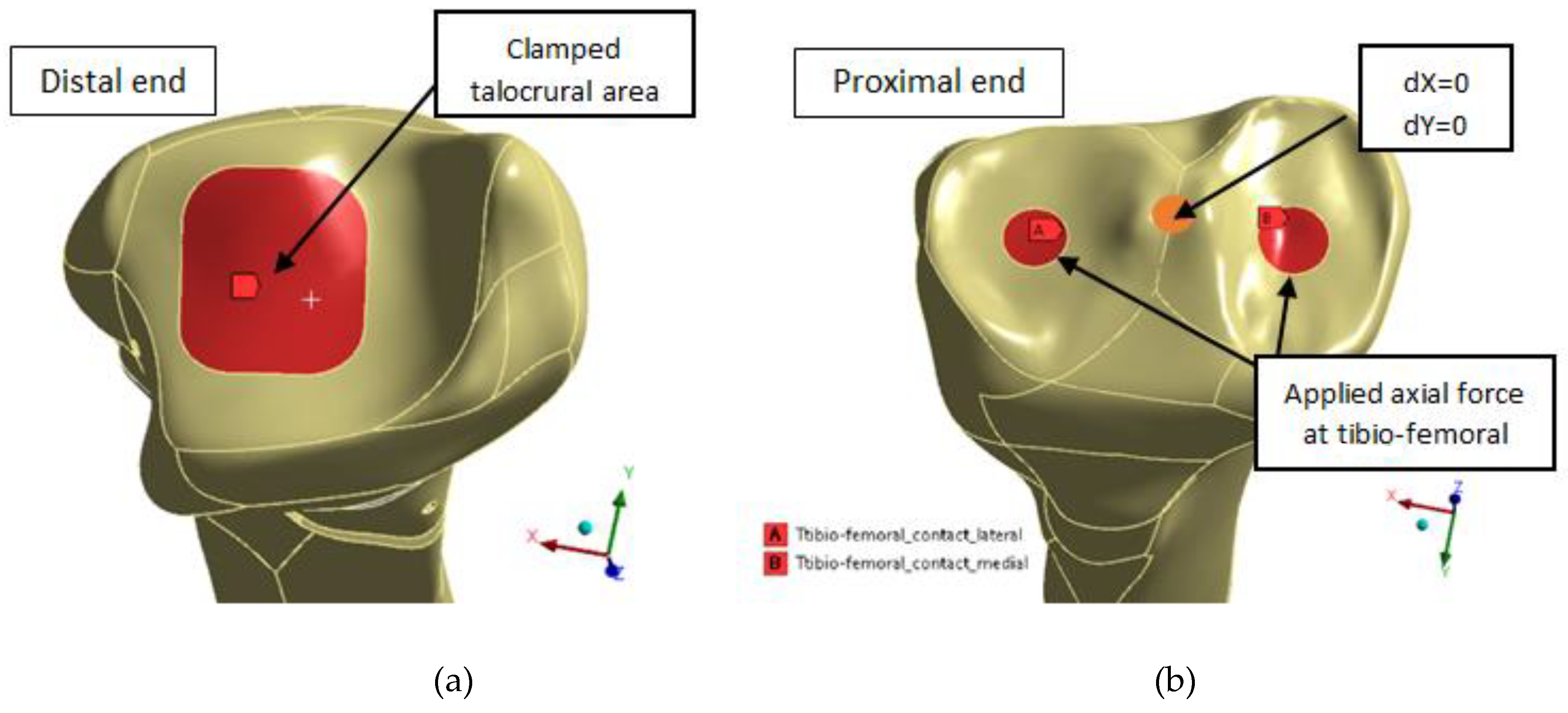
In the distal end of the tibia (
Figure 6a), the talocrural joint area of 417 mm
2, corresponding to the mean ankle cartilage contact area as in [
34], was fixed. According to Wan et al. [
42], this area is located slightly more laterally and centrally on the talocrural joint surfaces as seen in the left side of
Figure 6.
The tibia was loaded at the proximal end (
Figure 6b) by an applied axial force corresponding to the weight of a 70 kg male at the areas shown on right side of
Figure 6, corresponding to the mean lateral and medial tibio-femoral contact area for 30 to 90 degrees of knee flexion.
Three different loading scenarios are analyzed with applied gravity load in Z- direction of 0.1 g (70 N) corresponding to lying down and swing stance position [
12,
22], 0.5 g (350 N) corresponding to two-legs stance position, and 1 g (700 N) corresponding to one-leg stance cases, necessary to be able to walk without assistance.
As per Eisenhart-Rothe et al. [
43], the contact was located in the central side of both lateral and medial tibia articular cartilage. The size of the medial contact areas is 122 mm
2. In all knees, the medial contact area is slightly larger than the lateral. The lateral, anterior, and posterior borders of the tibial articular cartilage have no contact.
The displacement in the XY transverse plane was constrained to take into account the knee joint and the fixing point in a future test bench.
The contacts between the fragment, callus, and bone, the three K-wires, and the distal end/fragment and between the two pins and middle tibia bone were modeled with friction coefficient of 0.4 [
12,
30], and adjusted to touch interface treatment. These settings were used to improve contact accuracy, given the fact that the bodies are just about to come into contact or include a very small gap. Bonded contact was considered for the other elements of the EF such as between fasteners and K-wires or ring connections.
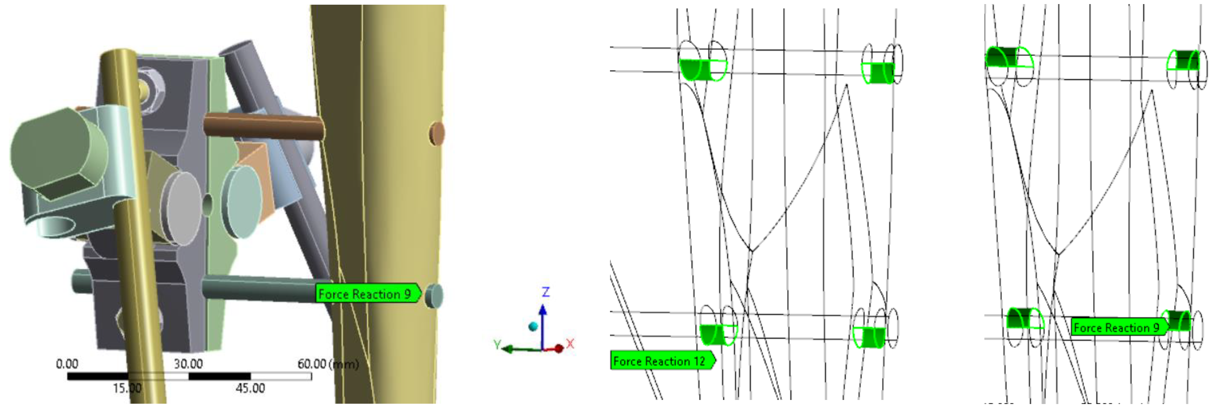
Reactions at pin interface were analyzed to assess the level of load transfer assured by EF in with callus at fracture site configurations only, and thus its effectiveness while healing. The sum of reaction forces from upper and lower side of the contact were considered as the pins are squeezed by the compressed bone resulting in reaction forces in Z+ direction in one side and Z- on the other side as shown in
Figure 7.
As presented in the research methodology (
Figure 1), for some configurations, wire pre-tension of up to 1000 N was considered in order to evaluate the impact on the global stiffness of the EF and to increase its effectiveness.
2.4.2. Ring Design and Boundary Conditions
In evaluating ring design modifications, the analysis considered configurations featuring a 160 mm diameter ring and three K-wires (1.8 mm in diameter), each subjected to 500 N and 1000 N of pre-tension. Four distinct ring designs were analyzed to assess their structural performance and adaptability under varying pre-tension loads, as presented in
Figure 8. The configurations are inspired from designs currently available on market: full rings and rings with connecting flanges [
44].
The baseline configuration remained consistent with the initial stress assessment and early healing stage analysis. In the new 5/8 ring design, the net section was increased to enhance transverse stiffness. Additionally, extra holes were incorporated to allow for potential connections with additional rings, facilitating future EF designs that involve stacked ring configurations.
In the full ring configuration, an additional segment (visible in yellow color in
Figure 8c,d) was incorporated to fully enclose the ring, creating a complete structure. The same modification was applied to the new 5/8 ring design to assess the impact of increased transverse net section on structural performance. These configurations were analyzed comparatively, considering both metallic rings and 3D-printed PLA-CF alternatives.
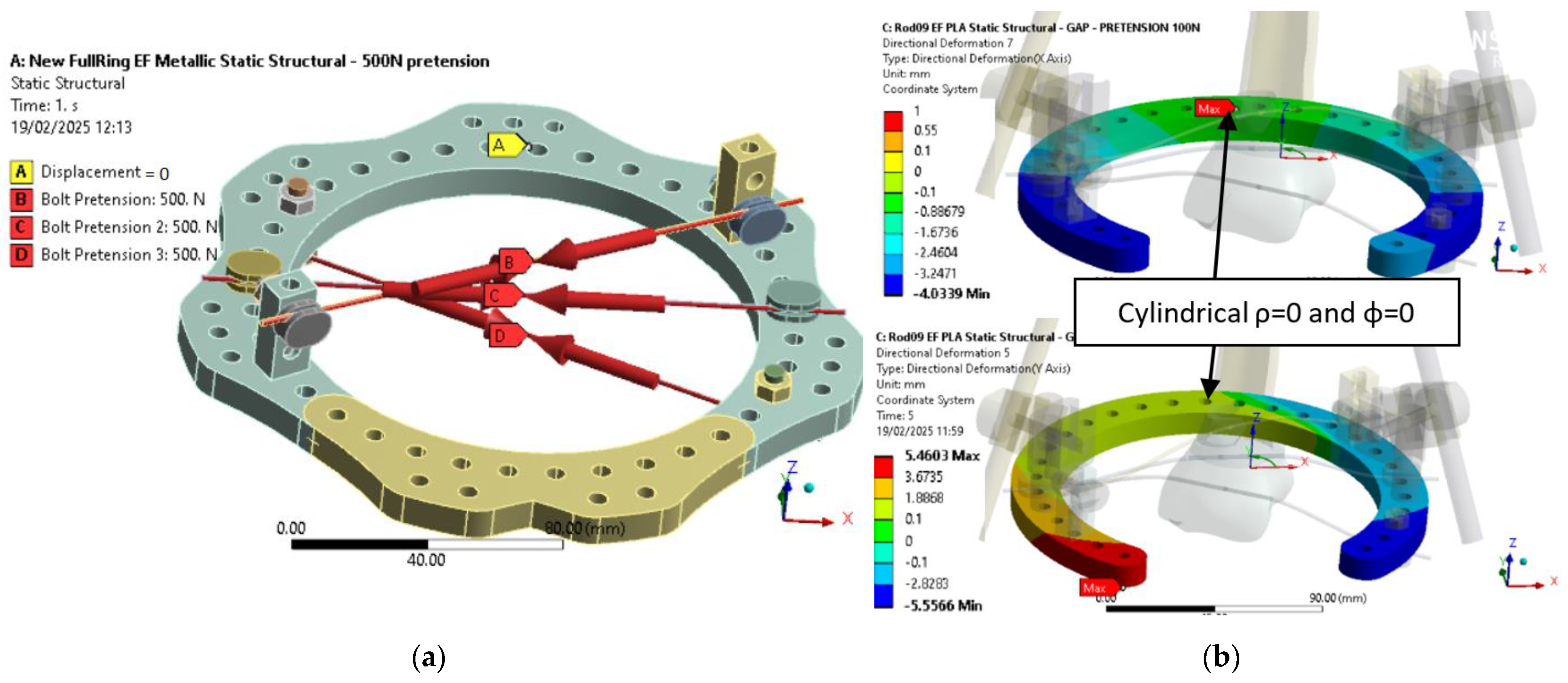
As shown in
Figure 9, boundary conditions were consistent with the initial assessment. For the metallic ring (
Figure 9a), three pre-tension forces of 500 N simulated wire loading, and one node was fixed to ensure isostatic constraint. For the PLA-CF configuration (
Figure 9b),
Z-axis directional deformation is presented for two geometries under 100 N pre-tension. In both cases, the fixed node was placed at the cylindrical coordinate origin (ρ = 0, φ = 0), corresponding to a zone of minimal displacement. This setup ensures consistency across simulations and enables direct comparison of deformation responses.
3. Results and Discussions
3.1. Results for Configuration with Gap—Initial Stage
The EF strength and stiffness results for the scenario without any callus formation (with a fracture gap) are presented in
Table 2 for 0.1 g, 0.5 g, and 1 g loads, where g is the gravitational force equivalent for a 70 kg male expressed in N as explained in
Section 2.4.1, corresponding to the sit-down position, two-legs stance, and one-leg stance cases.
The stress levels, safety factors under 1 in
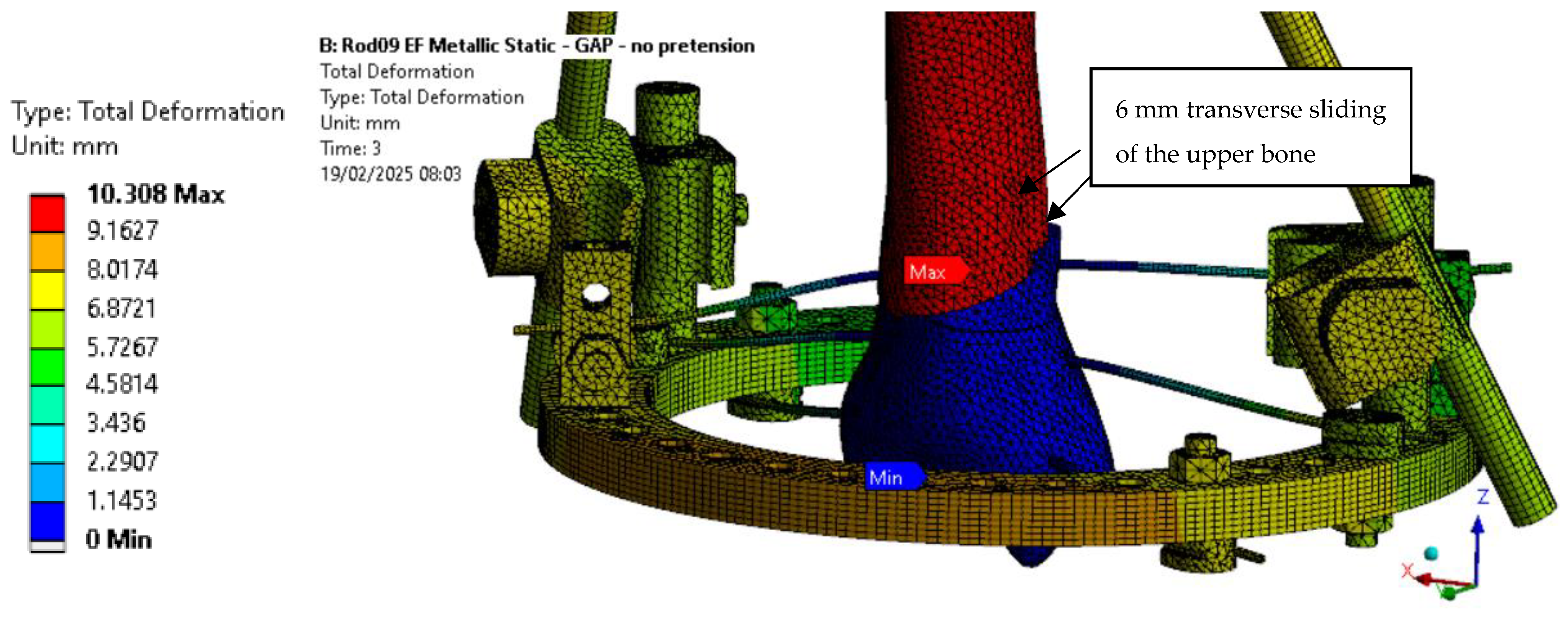
Table 2, exceed the allowable limit of the respective components. Acceptable results were observed only for the 0.1 g case with a 500 N wire pre-tension. In the 1000 N pre-tension case, all stress values remained within limits except for the EF ring, which exceeded the allowable threshold. Moreover, a progressive increase in the Y displacement was noted with both higher applied loads and increased wire pre-tension. This behavior is attributed to the pin placement, which is 121 mm away from the fracture site. The sliding of the pins, combined with this positioning, induces a rotational movement at the fracture location, contributing to the observed displacements.
Applying wire pre-tension was shown to reduce the VM stress in the wires and clamps for both the two-leg and one-leg stance cases, while also lowering the stress in the bone. However, an increase in VM stress was observed in the pins, rods, and EF ring as the pre-tension increased.
Regarding the PLA-CF ring configuration (
Table 3), only the case without wire tension and with 100 N of wire tension were analyzed, as the calculations for a wire pre-tension of 500 N or higher failed to converge, due to excessive deformations, which led to element distortion in the simulation.
For the PLA-CF ring configuration, compared to the metallic counterpart, stiffness is reduced by 25% under 0.1 g axial loading and by 21% with wire pre-tension applied, becoming half of the metallic configuration stiffness under 1 g axial loading.
In terms of strength, the VM stress levels in the PLA-CF components remain below 42 MPa, regardless of the applied axial load (
Figure 10). To further validate these findings, additional research should explore the effects of higher wire pre-tension on the structural behavior of PLA-CF rings.
As presented in
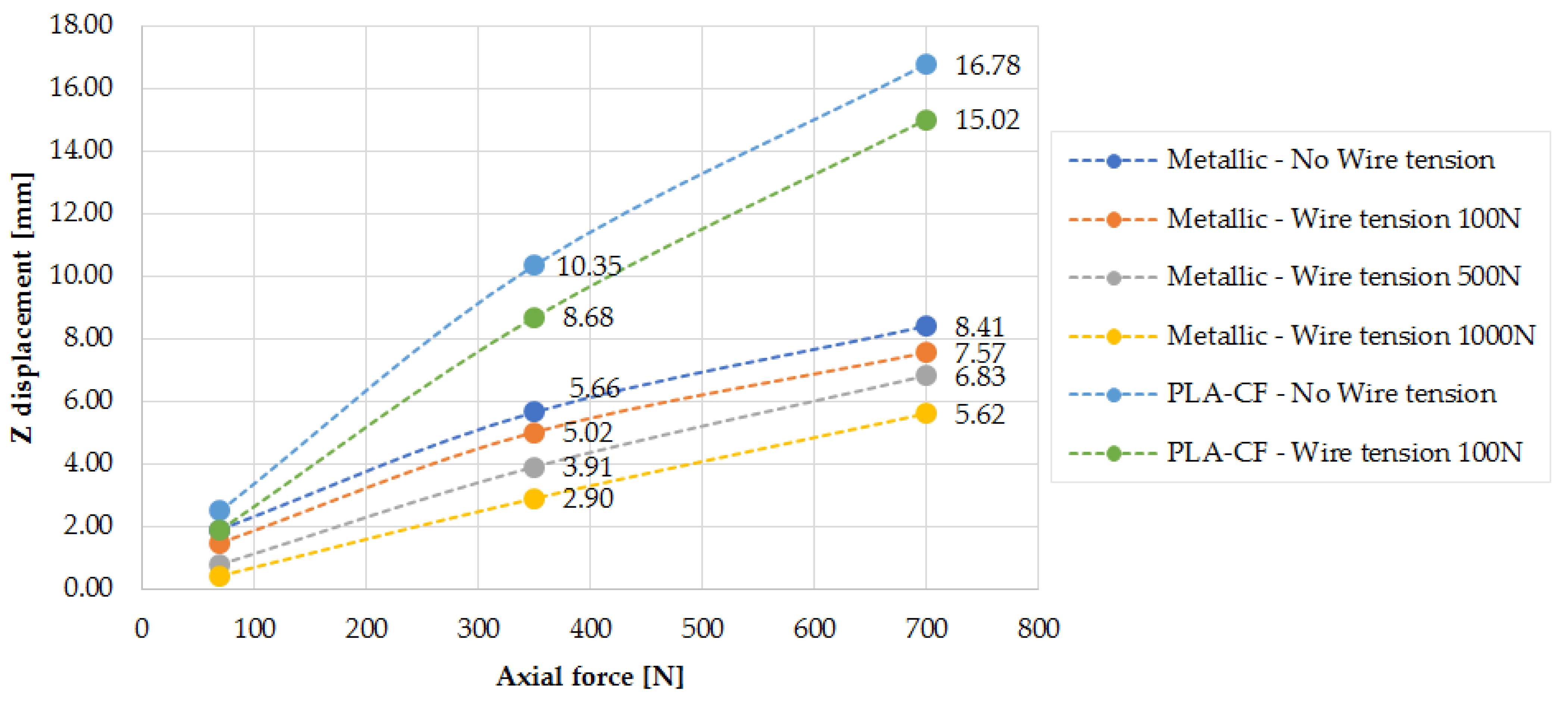
Figure 11, EF stiffness increases with the applied wire pre-tension, a trend that is also confirmed by the findings in [
3]. The Z displacement increases with the axial applied load, though not in a perfectly linear manner. This deviation can be attributed to sliding effects at the bone-to-pin and bone-to-wire contact interfaces, which influence the overall displacement behavior.
For both the metallic and PLA-CF EF configurations, achieving an early weight-bearing capability immediately after surgery is not feasible. The patient should remain in full bed rest for a period to allow for callus formation and the initial healing of the fracture gap. Although the 0.1 g load case without wire pre-tension results give acceptable stress levels across all components, it is not considered viable because the axial displacement exceeds 33% of the initial 3 mm gap size, making it structurally insufficient. Therefore, a minimum of 500 N wire pre-tension is required. For the 1000 N pre-tension case, all stress values remain within allowable limits except for the EF ring, suggesting that a ring redesign is necessary in order to accommodate higher preloads.
Furthermore, as seen in
Figure 12, the transverse displacement values are excessively high and further increase with wire pre-tension, raising concerns about the current design’s ability to effectively stabilize the fracture site. This effect is attributed to the pin placement, as already mentioned. Along with pin sliding, this configuration induces a rotational movement at the fracture location. To address this issue in future designs, the distance between the pins and the fracture site should be reduced to minimize transverse displacement.
Since applying wire pre-tension has been shown to reduce von Mises stress in the wires and clamps for both the two-leg and one-leg stance cases, while also lowering stress in the bone, it can be concluded that wire pre-tension is a mandatory step for effective EF function. However, the increase in VM stress in the pins and EF ring with higher pre-tension should be carefully considered in future EF ring designs in order to avoid structural failure.
For the PLA-CF configuration, the VM stress levels remain below the allowable value of the 3D-printed components, confirming that the strength criteria for these parts are satisfied.
3.2. Results for Scenario with Callus Formation
The scenarios taking into account the impact of callus formation are presented next. The first four weeks after EF placement are considered, as full weight-bearing should be feasible during this period based on the clinical practice.
The following situations were analyzed: (1) metallic EF without wire pre-tension; (2) metallic EF with 500 N of wire pre-tension; and (3) 3D-printed PLA-CF ring without wire pre-tension. It should be mentioned that, for the PLA-CF ring, as shown in gap configuration analyses, for the current design, it was not possible to apply 500 N of wire pre-tension or more as the calculation convergence criteria were not satisfied within a reasonable number of iterations (<100).
The pin reaction force was used to quantify the load transferred by the EF for each healing phase.
Table 4 shows the pin reaction force (Fr) evolution for the case with a 0.1 g sit position in conjunction with the percentage of the total axial applied load of 70 N (P%). The following aspects can be observed:
Pin reactions decrease with the healing of the fracture as the bone is taking a higher load and the EF is less effective;
Pin reactions are similar for metallic and PLA-CF EF configurations;
Adding the pre-stress for metallic EF was found to significantly increase the pin reactions.
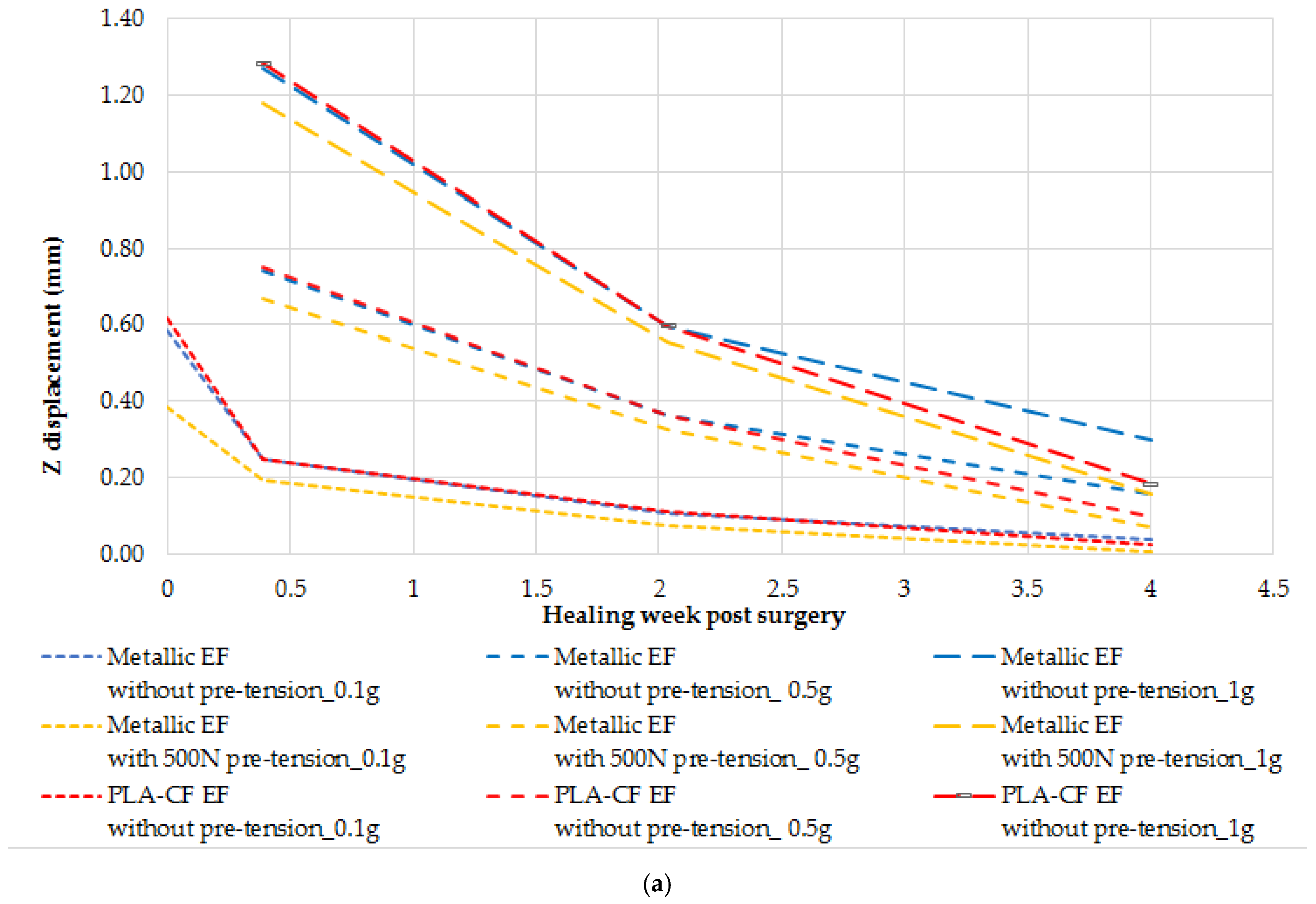
Figure 13 presents the displacements in the axial Z direction and in the transverse Y direction for different callus ages (i.e., stiffness). As observed, the displacements are within acceptable limits (less than 30% in the axial direction and 15% in the transverse direction), except for the fibrous callus under 1 g axial loading corresponding to the one-leg stance condition necessary to walk. The results showed that, due to high displacements at the fracture site, if healing proceeds normally, full weight bearing should be possible at the earliest after 2 weeks post-surgery.
The stress values for the steel EF without pre-tension configuration are presented in
Table 5, while
Table 6 shows the stress values for the 3D-printed PLA-CF EF without pre-tension.
For the granulation tissue callus stage, only the 0.1 g loading case was analyzed, as the patient remains in bed rest during the first postoperative day. The stress values obtained for the metallic EF configuration are within acceptable limits for all components. As callus healing progresses, stress values decrease significantly, indicating improved load distribution and enhanced structural stability of the fixator–bone configuration.
The stress values obtained for the PLA-CF EF configuration are similar with those of the metallic EF configuration (
Table 7). The wires and the ring stresses are, on average, about 12%, and 70% lower for the PLA-CF EF configuration, while the callus stress is up to 4% higher.
The stress values for the metallic EF with 500 N of wire pre-tension configuration are shown in
Table 7, a significant increase in stress values being observed mainly in the wires and in the EF ring (
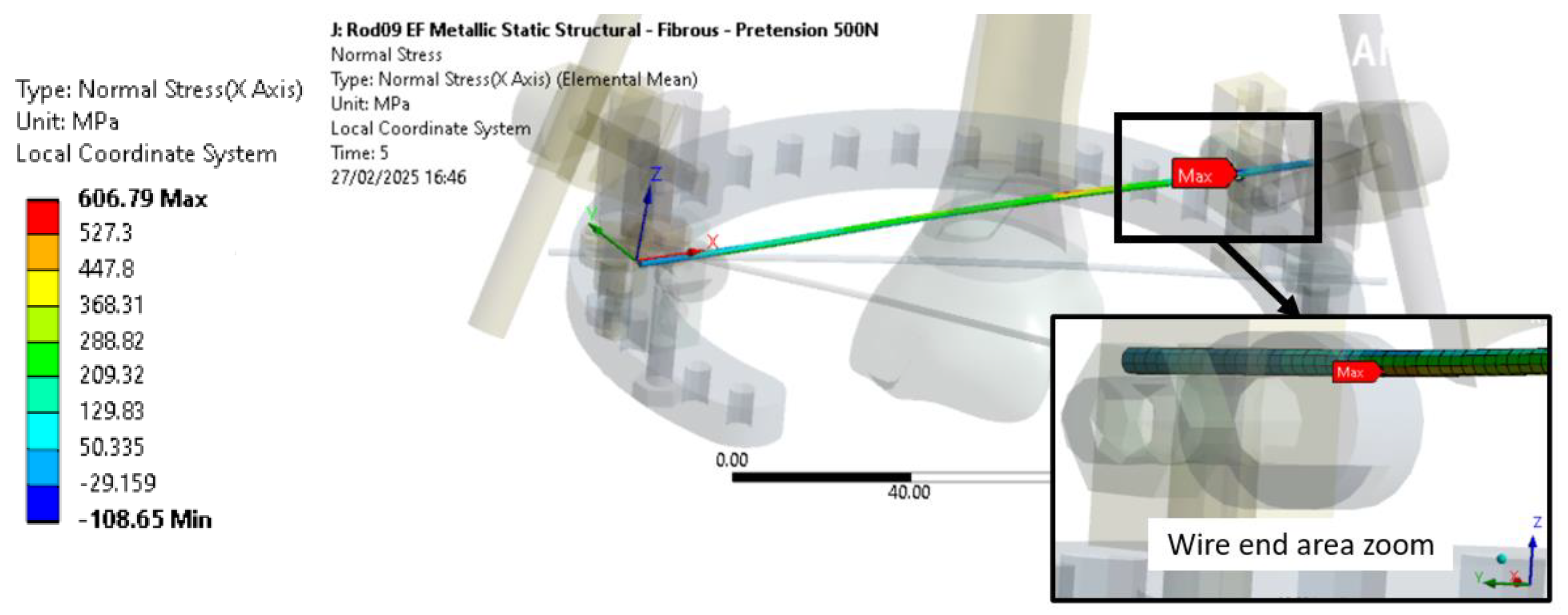
Figure 14). However, the stress values remain acceptable.
As shown in
Figure 14, the maximum normal stress is obtained for wires 1 located near the ring clamp area and is due to both the wire pre-tension load and the axial load applied at the distal end.
Regarding the EF ring, the stress is produced mainly due to the wire pre-tension load, as no significant safety factor evolution with an axial load is shown in
Table 7. Thus, the impact of the axial load of the EF ring is limited for the cases with callus formation, but could increase for configurations with a higher EF stiffness as the fixator will support a higher ratio of axial load.
3.3. Results for Ring-Only Configurations—Design Change Evaluation
The results for different analyzed ring-only configurations are shown in
Table 8, with the results exceeding the tensile strength allowable criteria or having high displacements highlighted in bold.
For baseline ring, the displacements for the 3D-printed PLA-CF EF configuration are almost 100 times higher than those of the metallic EF. The stresses of the 3D-printed PLA-CF EF configuration are also exceeding the allowable values of the studied parts; thus, preloads of 1000 N or even 500 N cannot be applied on the current baseline configuration using 3D-printed PLA-CF.
The displacements for the 3D-printed PLA-CF EF configuration are almost 20 times higher than those of the baseline metallic ring, and thus five times lower with the new design. Moreover, the stress values obtained have decreased, but remain too high for the new design to be acceptable.
The displacements for the 3D-printed PLA-CF EF configuration with a full ring are only seven times higher than the baseline metallic configuration. A significant reduction in stress values was also observed.
The displacements for the 3D-printed PLA-CF EF with a new full ring configuration are about 4.8 times higher than the baseline metallic configuration. The stress has continued to decrease with the use of the new design with up to 84% at 1000 N pre-tension compared to the initial baseline configuration, but the maximum stress is located in an area where the transverse net section is in the minimum, topological optimization being required to further improve the ring design.
A true scale deformed plot showing the PLA-CF ring VM stress is shown in
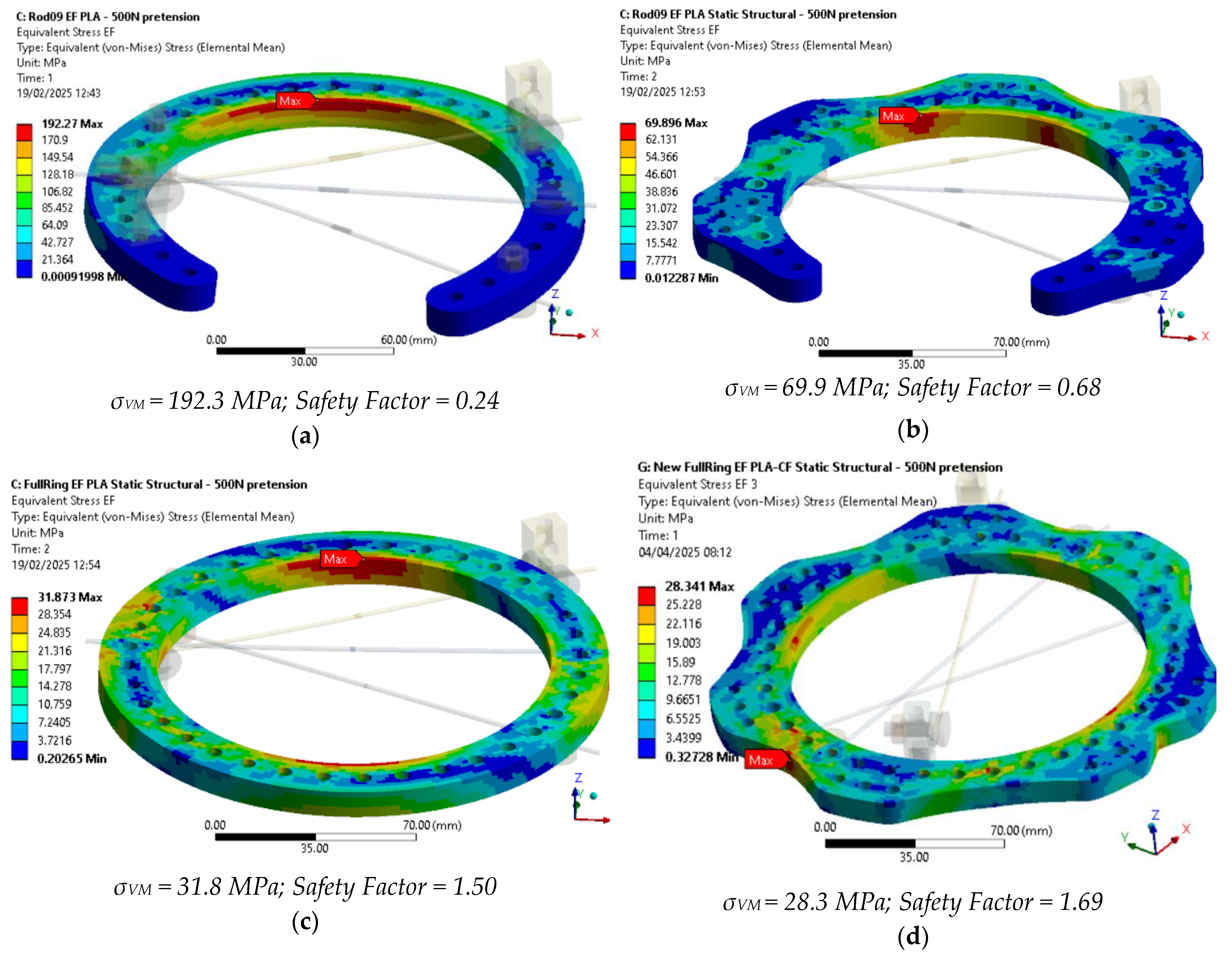
Figure 15 for the studied configurations under 500 N of wire pre-tension, providing safety factors above 1.5 for full ring designs.
For 500 N wire pre-tension, the ring stress levels remain below the allowable limit for PLA + CF. However, at 1000 N wire pre-tension, the strength criterion is not met, indicating a need for design modifications. To address this, alternative designs incorporating an additional ring with only two wires per ring should be considered. As demonstrated in [
45] for Ilizarov fixators, configurations with two rings exhibit better mechanical behavior and higher structural strength.
The results presented in
Table 9 correspond to the new full ring configuration with only two wires per ring. In the first case, offset wire 1 was removed, while, in the second case, wire 2 was suppressed to evaluate the structural response under modified conditions.
For the new ring design with only wire 2 and wire 3, although both displacements and wire stresses are significantly reduced, the maximum VM stress in the ring decreases by only 5%, remaining above the PLA-CF ultimate strength. This is primarily due to both wire preloads acting along the direction of the lowest transverse net section, leading to high stress concentrations.
In the new ring design with only wire 1 and wire 3, the displacements increase significantly, and wire 3 experiences considerably higher stress than wire 1. However, the von Mises stress in the ring is reduced by up to 38% for the PLA + CF configuration at 1000 N wire pre-tension, meeting the strength criteria.
Furthermore, it can be observed that wire 1, as is offset from the ring using some connection posts, is producing an out-of-plane load that adds additional bending to the EF ring.
As reduced cost is seen as one of the advantages of 3D printing the EF rings, the cost of the new version presented in
Figure 15d was estimated at approximately €10–€15 (depending on filament producer), including the PLA-CF filament cost, 3D printer amortization, and energy consumption. In comparison, a conventional steel ring used in external fixators typically costs around €50–€150, due to the added expenses of CNC machining and labor, despite a lower raw material cost. This highlights the economic potential of using AM for producing these rings, especially for decentralized and resource-constrained medical settings.
4. Conclusions and Further Work
This study assessed the feasibility of 3D-printed EF rings made from PLA-CF as a lower-cost alternative to metallic fixators. FEA was conducted to evaluate their mechanical performance, focusing on stiffness, stress distribution, wire pre-tensioning effects, and callus formation impact, for different scenarios.
The main findings show that the PLA-CF rings exhibit approximately 25% lower stiffness than metallic rings at 0.1 g loading and 21% lower stiffness with wire pre-tension. For the metallic EF, the axial displacement under 1 g loading reached 8.41 mm without wire pre-tension, but this was reduced to 7.57 mm with 500 N pre-tension. However, transverse displacements remained significant, requiring design modifications to improve stability.
The early healing stage analysis (0–4 weeks) confirmed that callus formation significantly improves the load-bearing capacity of the EF–bone configuration. Prior studies indicated that callus stiffness progressively increases, ranging from about 0.04% at 0.5 weeks to about 60% of intact bone stiffness at 12 weeks. This gradual stiffening transfers mechanical stress from the fixator to the bone, reducing stress on EF components. In this study, the fracture displacements were about 90% at four weeks under 0.1 g loading, demonstrating improved stability. However, excessive displacement persisted at 1 g loading, suggesting that full weight-bearing should be delayed beyond two weeks post-surgery. The transition in the load transfer from the fixator to bone can serve as an objective criterion for fixator removal, as prolonged use of external fixation beyond the necessary period may hinder natural bone remodeling.
In the ring design assessment, the baseline PLA-CF ring exceeded its ultimate strength at 1000 N pre-tension, indicating a need for structural reinforcement. A full-ring configuration with two wires per ring improved performance, reducing von Mises stress by 38% compared with the three-wire configuration, keeping stress levels within acceptable limits. Additionally, increasing the transverse net section and redistributing wire attachment points further enhanced structural integrity. Thus, for 3D-printed rings, the use of full rings is found to be a better solution that may be suitable for the design of EF. However, a further redesign of the ring is needed to sustain preloads of 1000 N.
Given that PLA-CF stiffness is 42 times lower than that of metallic components, further geometric modifications are required in order to optimize load distribution and minimize displacements. Future studies should explore topological optimization, experimental validation under dynamic loading conditions, and stress-displacement analysis at anchor–bone interfaces, as anchor loosening remains a common failure mode in external fixators.
Overall, this study demonstrates the potential of 3D-printed PLA-CF fixator rings but underscores the need for design improvements to accommodate higher preloads, enhance transverse stiffness, and ensure long-term mechanical stability.
