
A Harmonic Suppression Method for the Single Phase PWM Rectifier in the Hydrogen Production Power Supply

Abstract
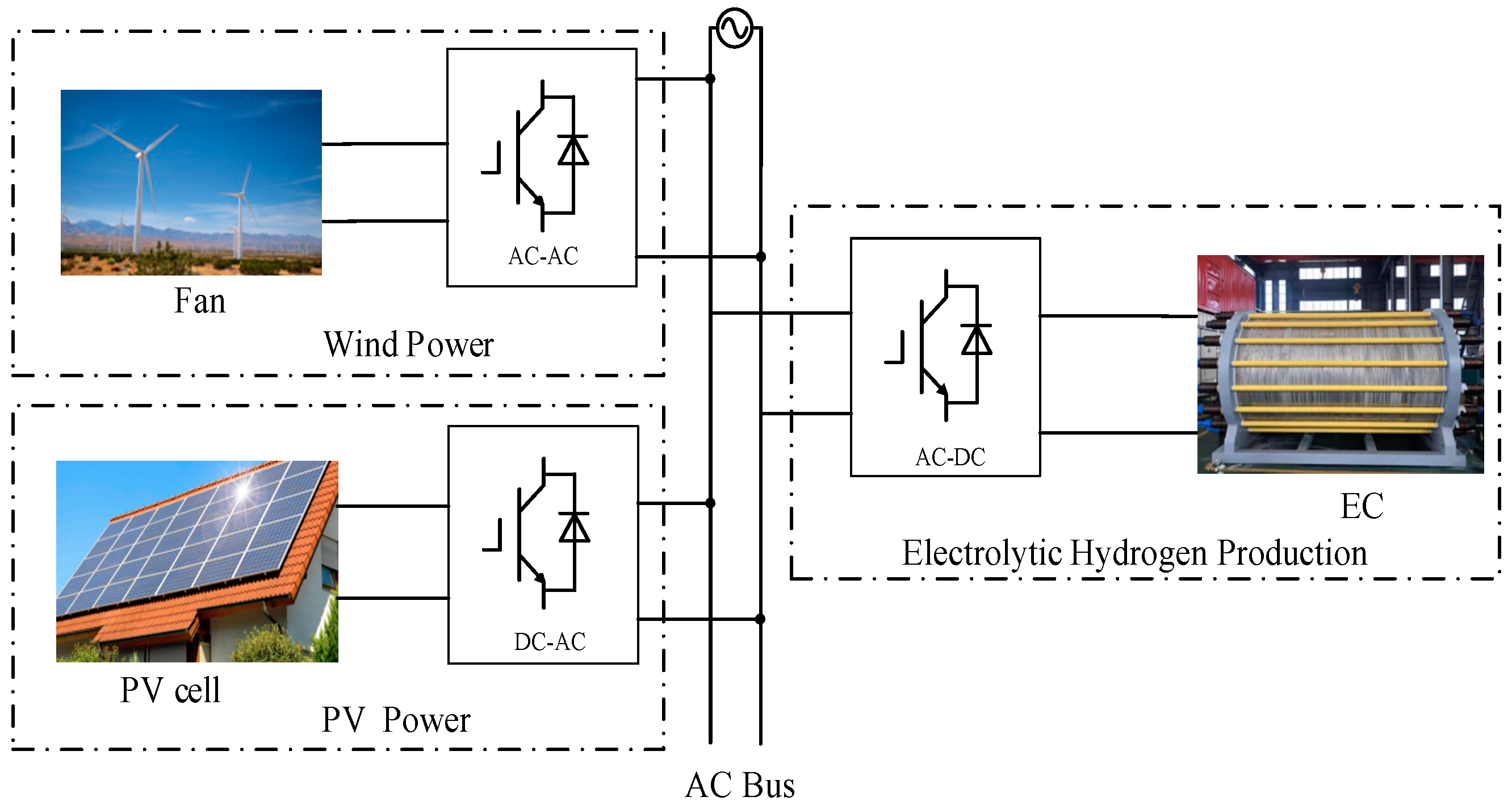
1. Introduction
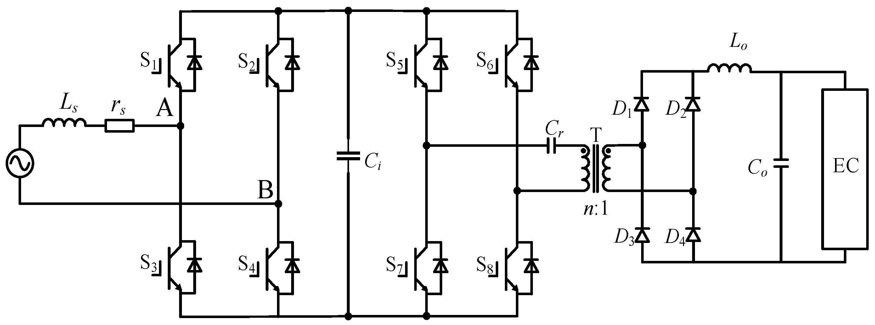
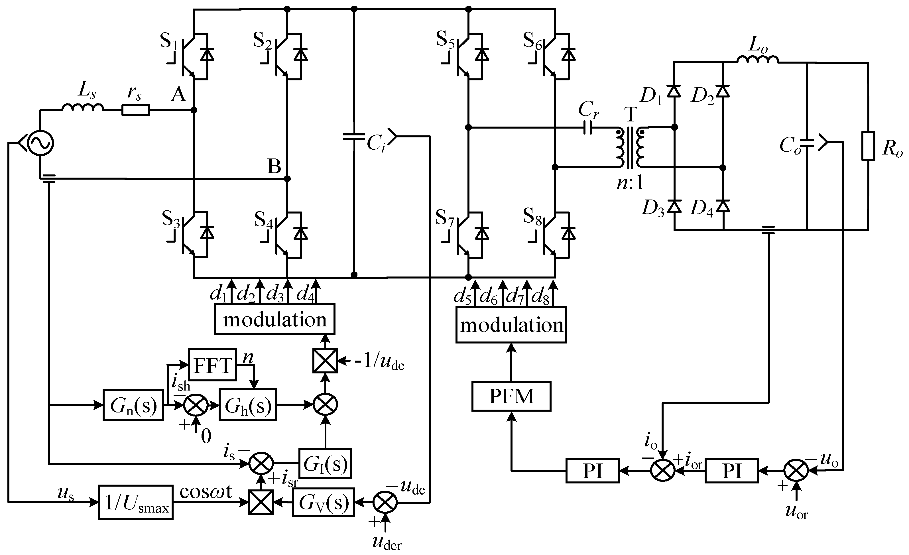
2. Topology and Control
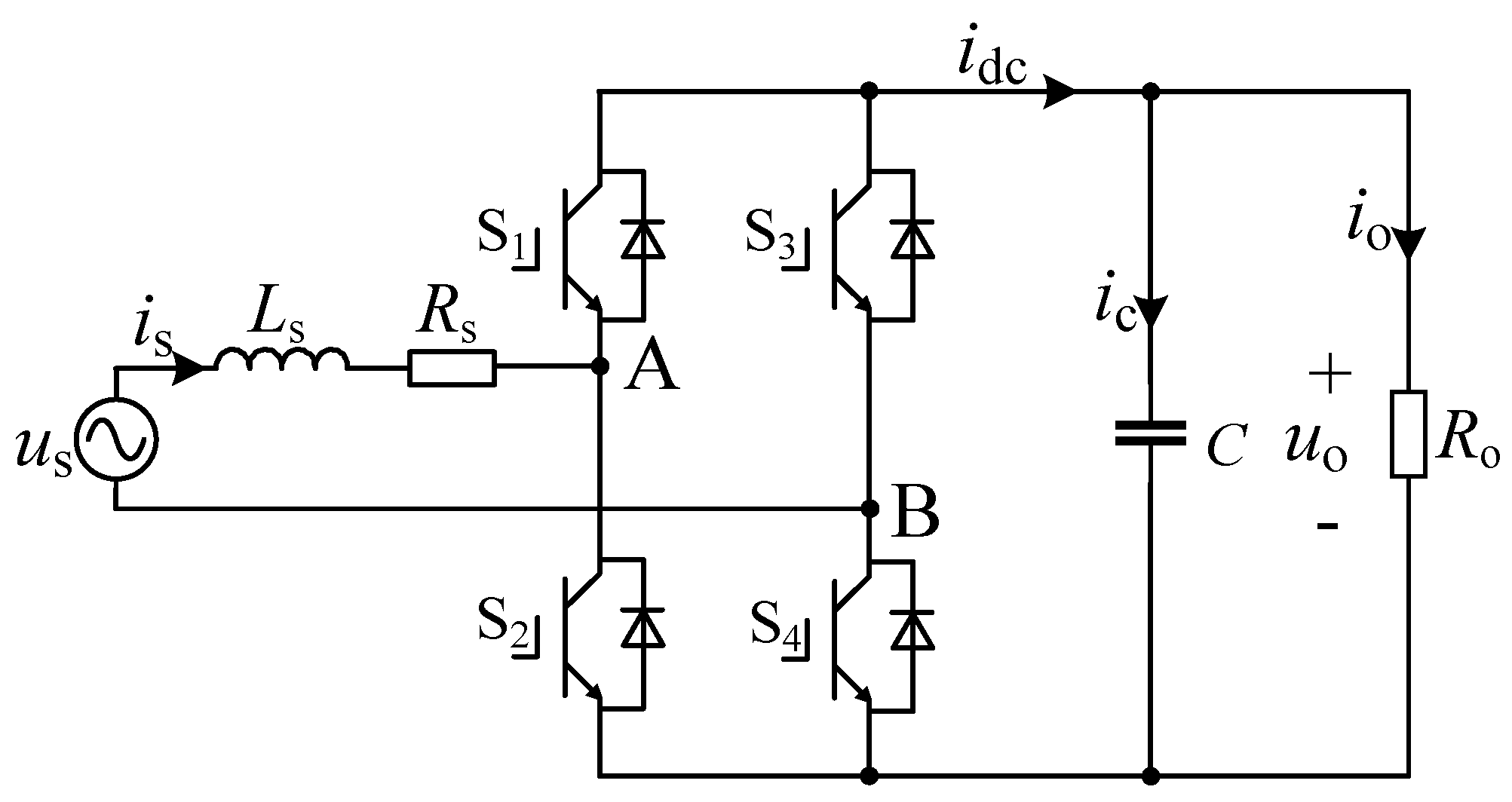
2.1. Topology
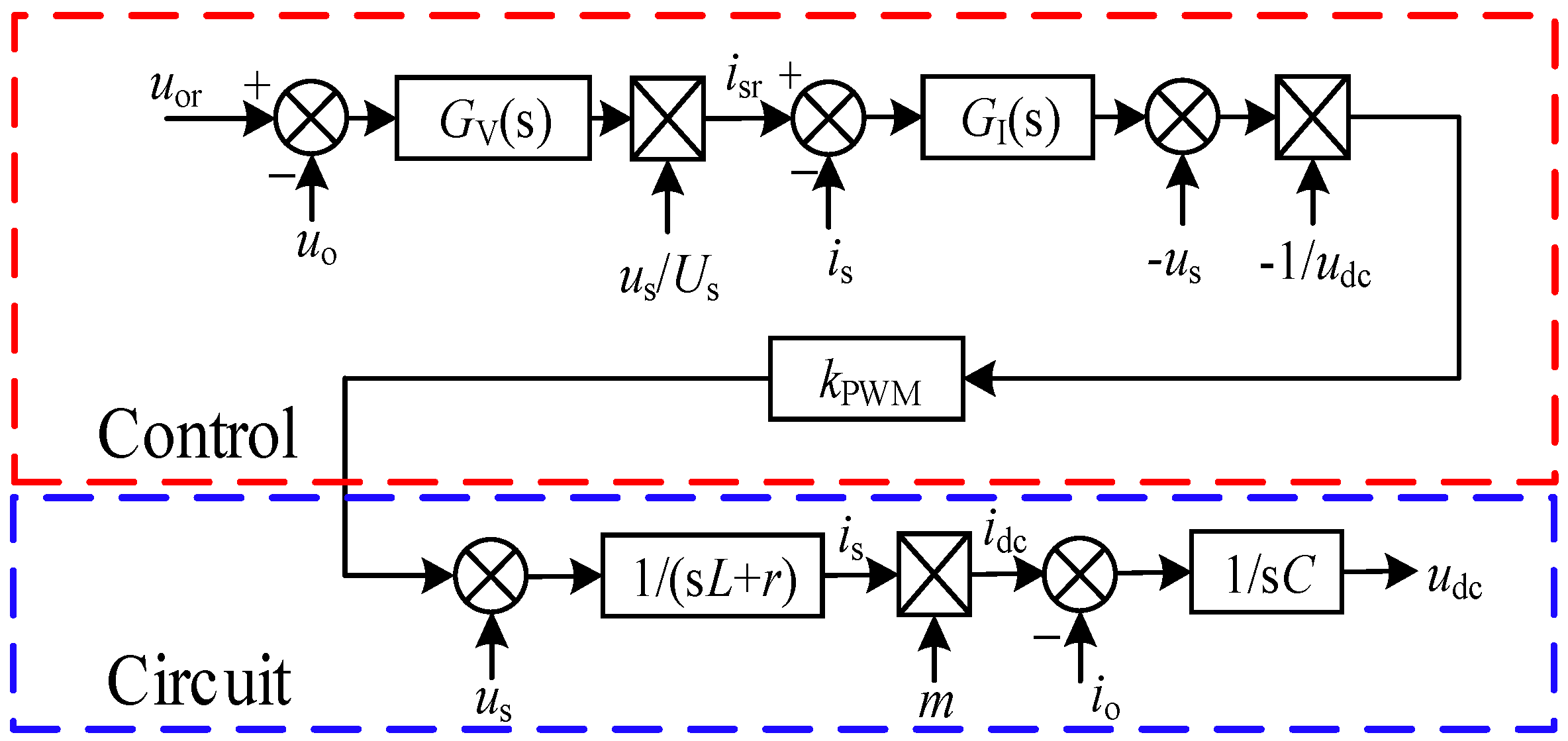
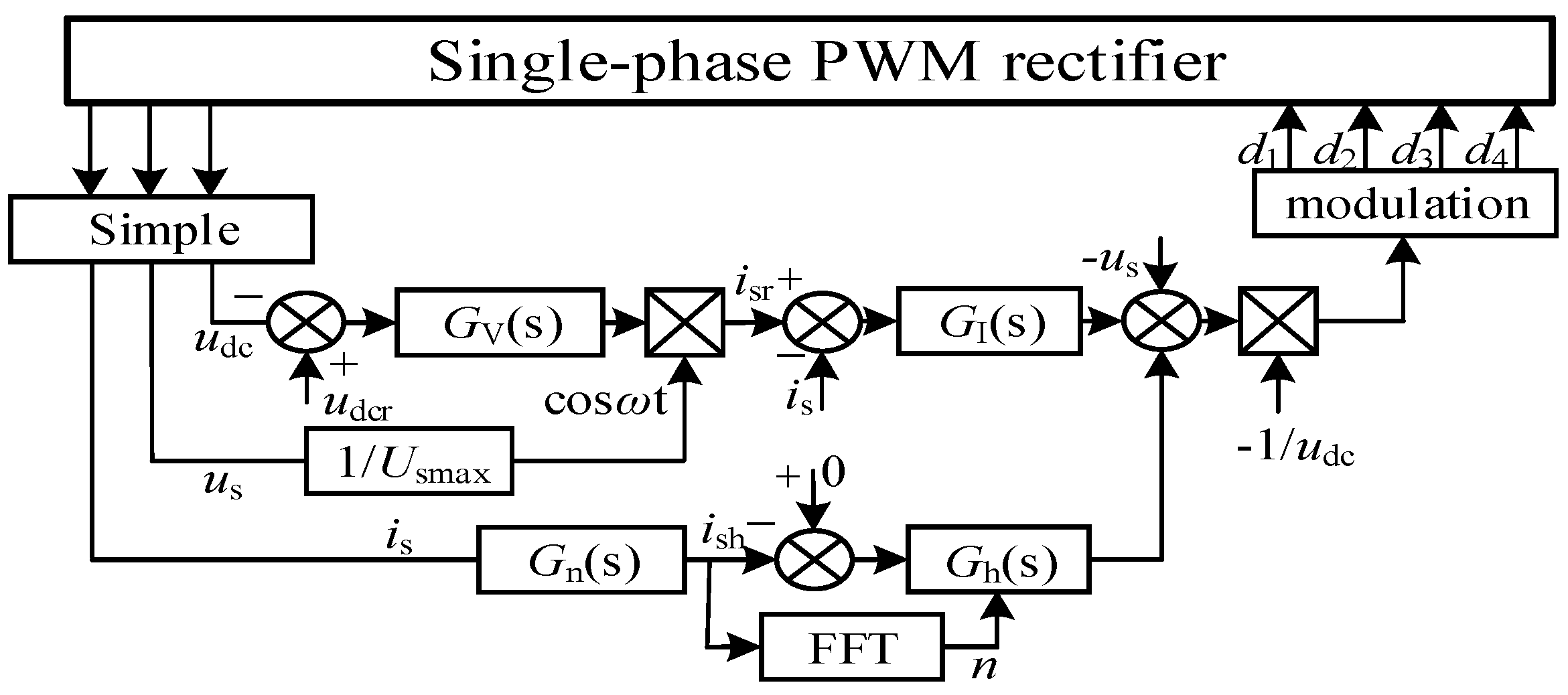
2.2. Control
3. Harmonic Model in RSHPES
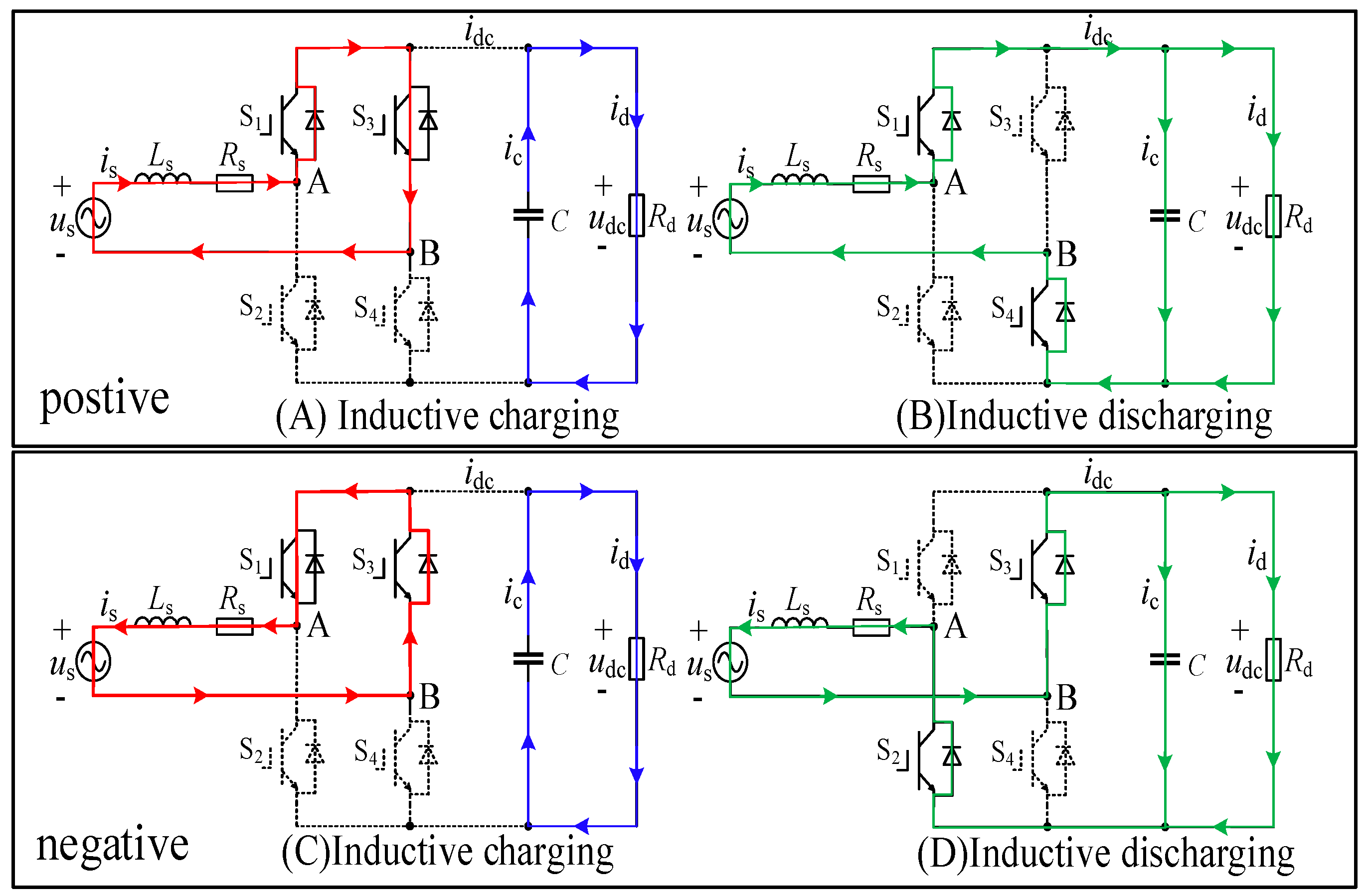
3.1. The Topology Aspect
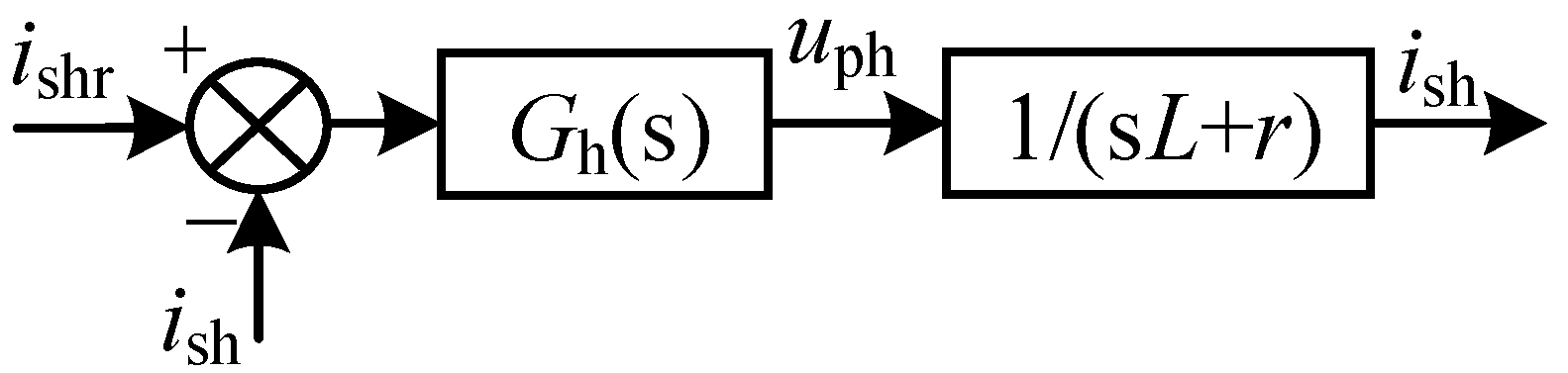
3.2. The Control Aspect
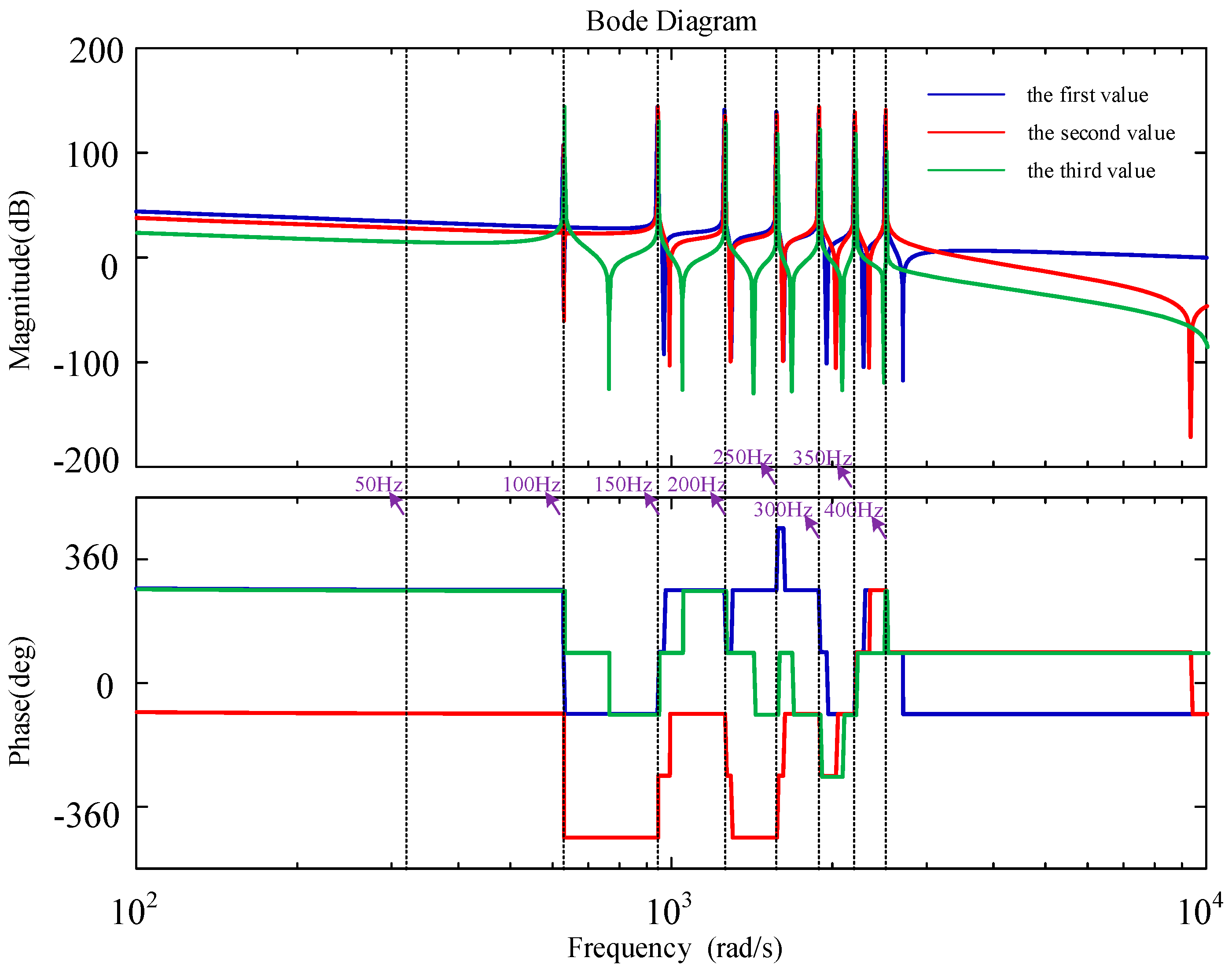
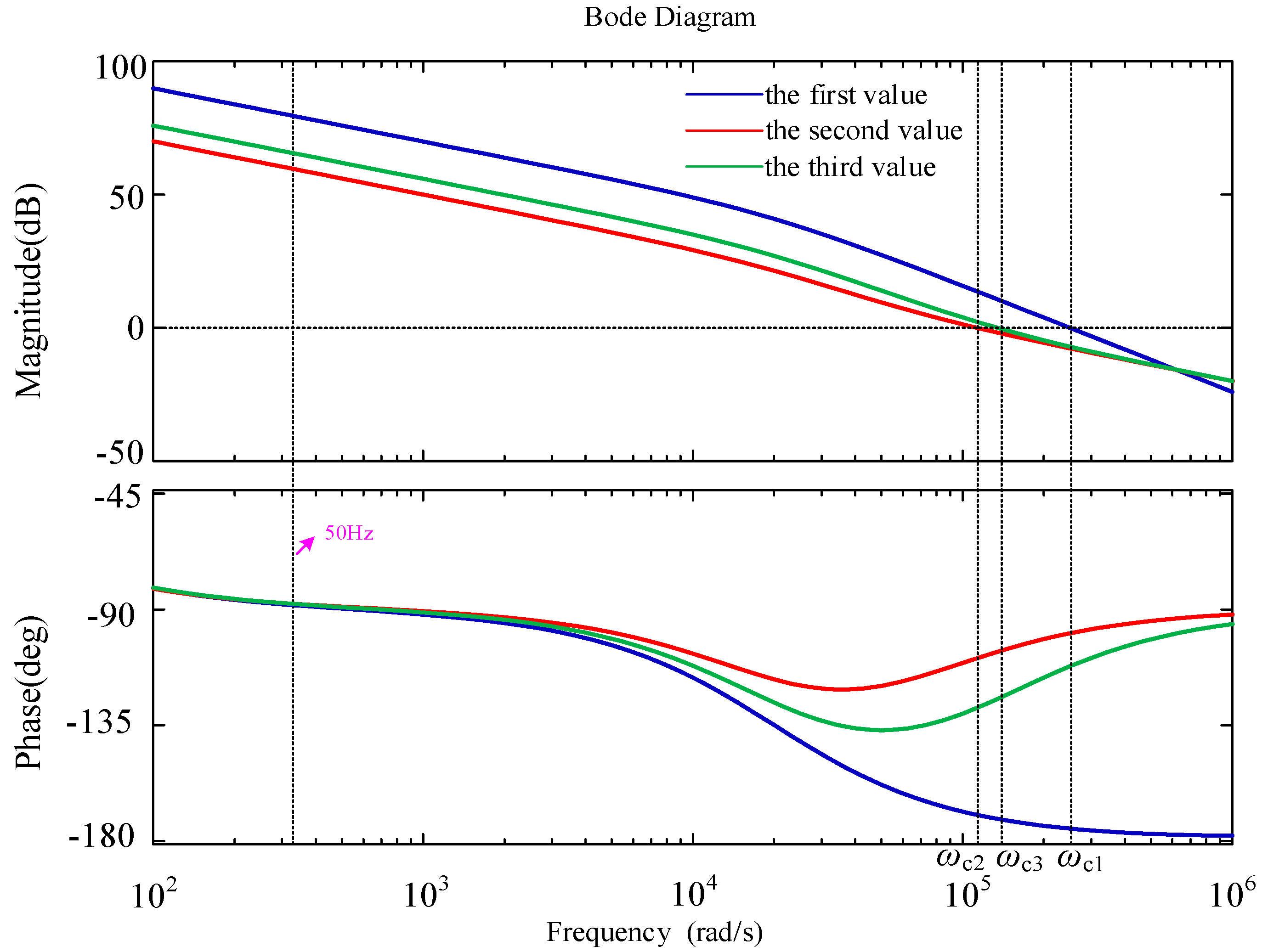
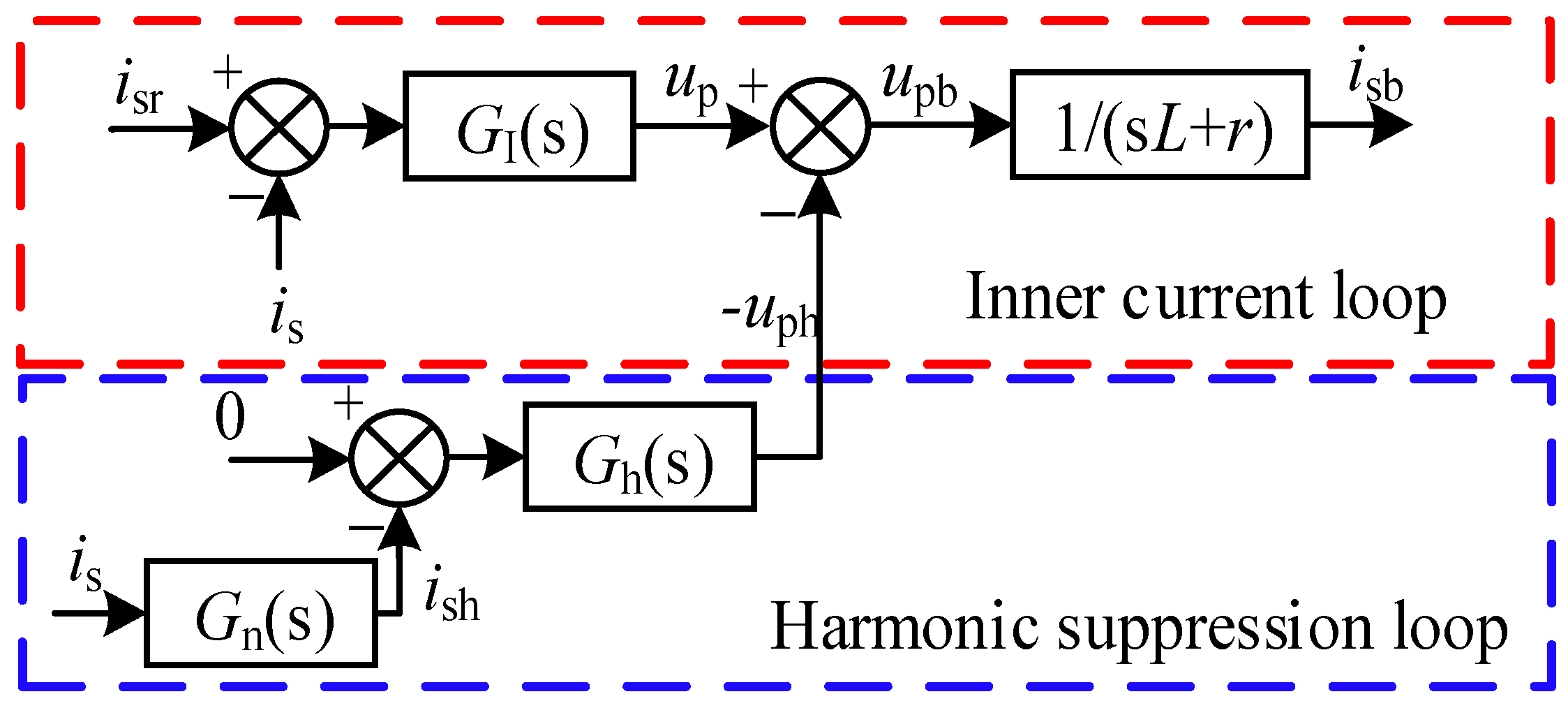
4. Harmonic Suppression Method
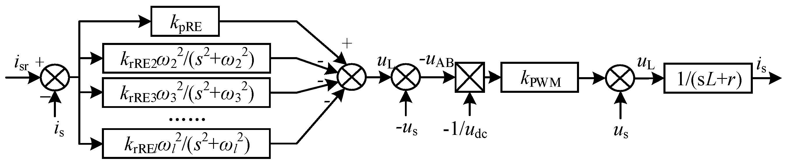
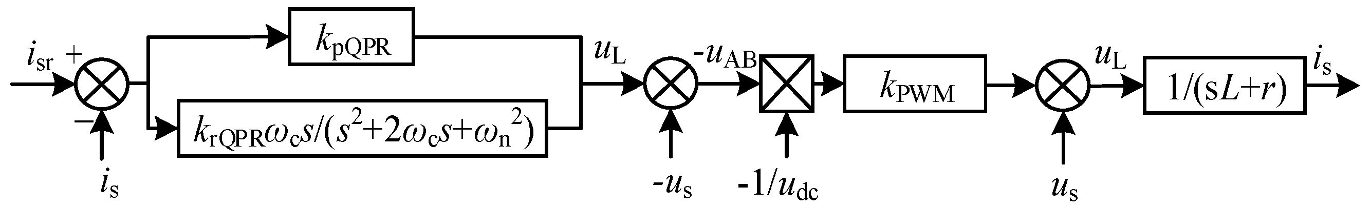
4.1. The Traditional Harmonic Suppression Method
4.2. HSCM
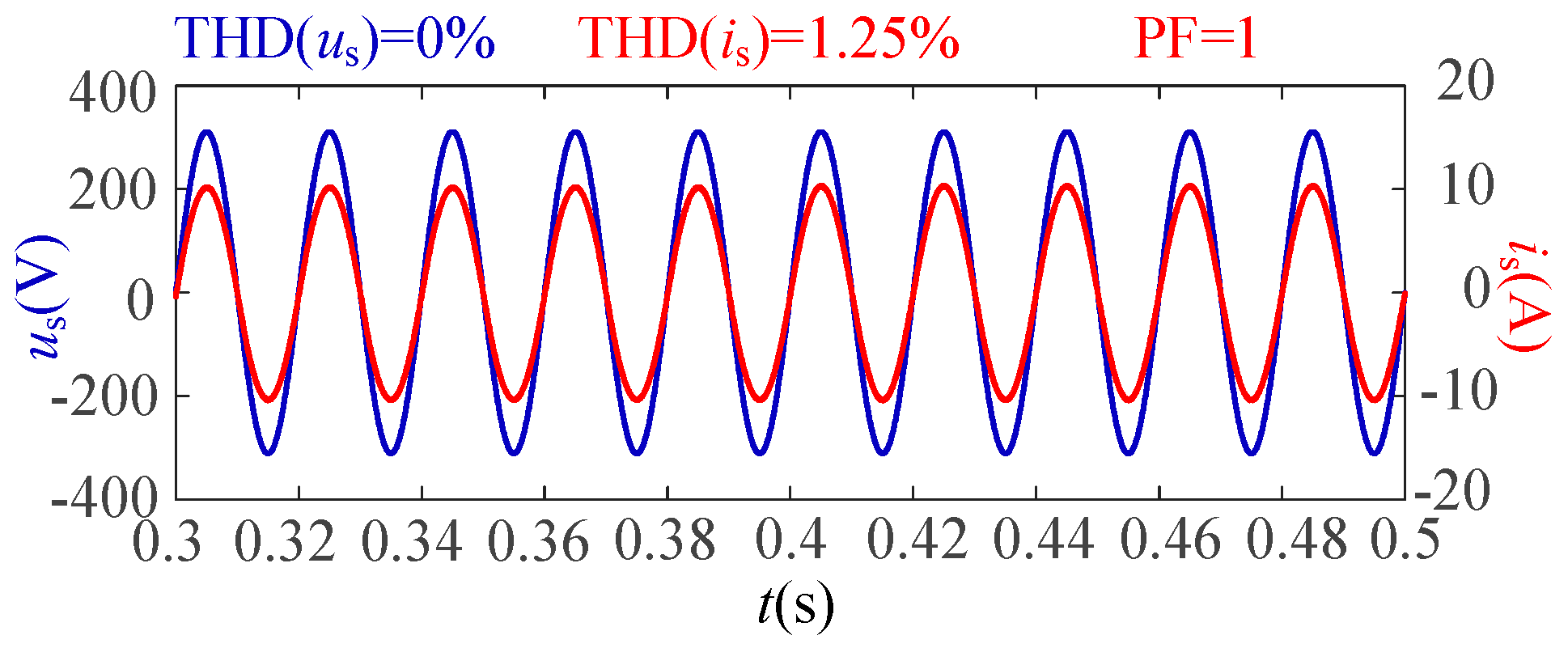
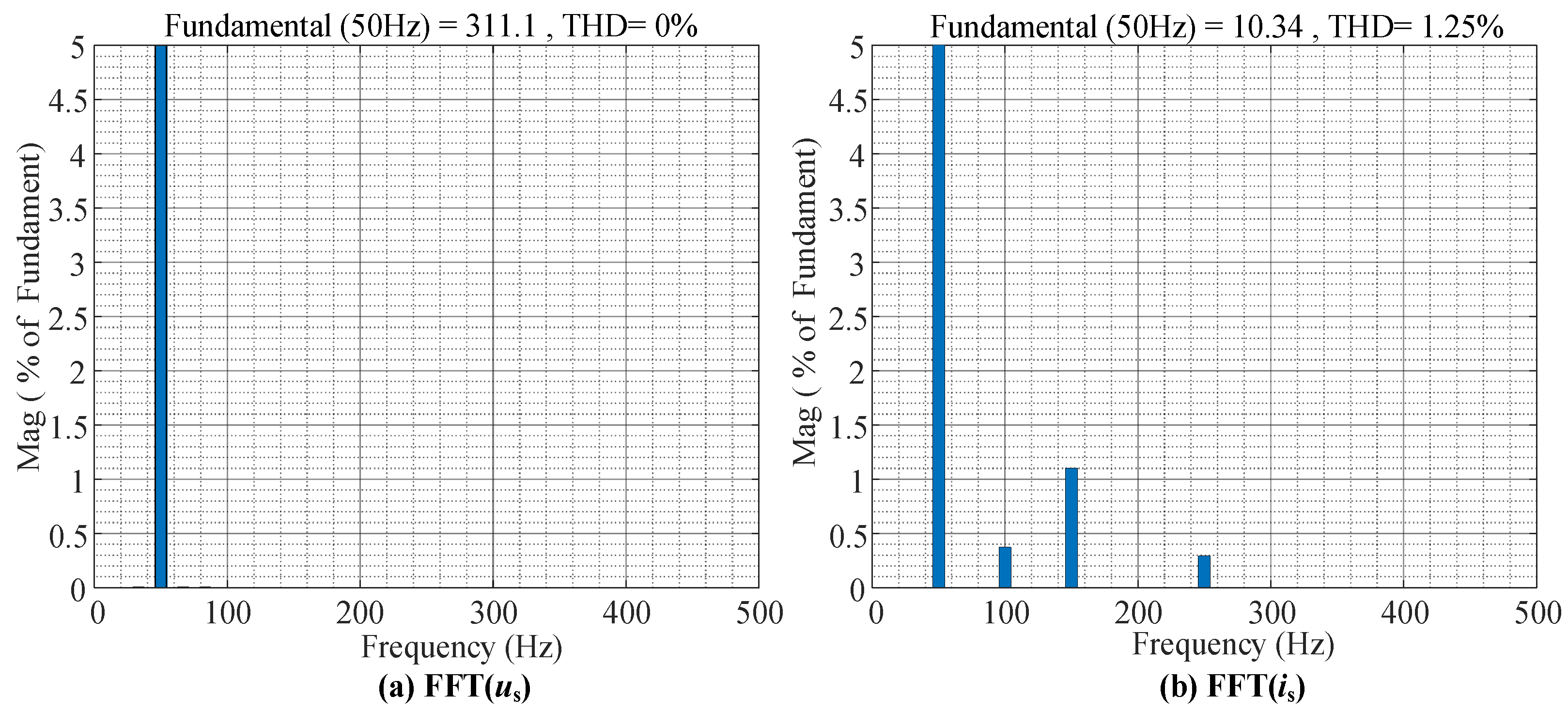
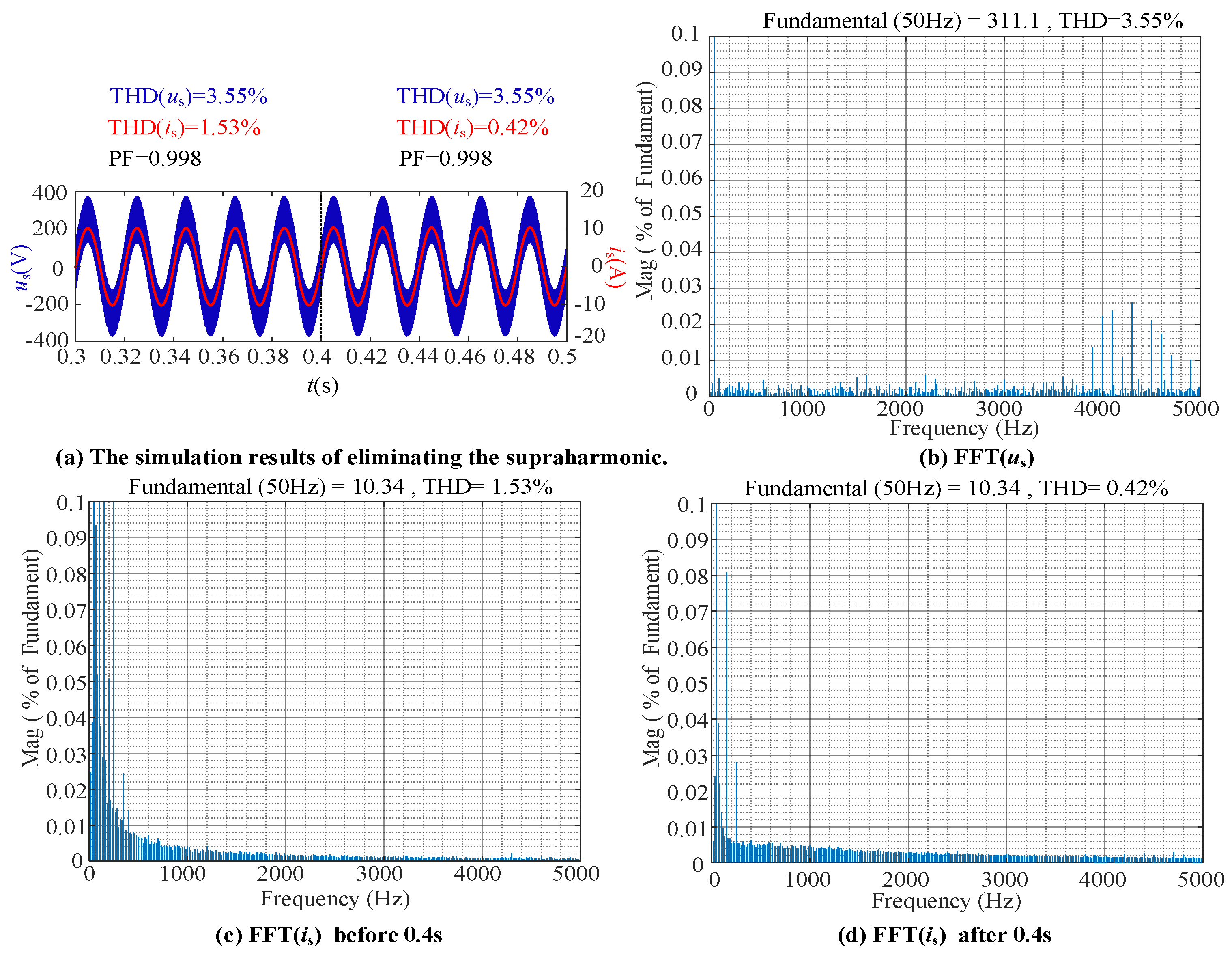
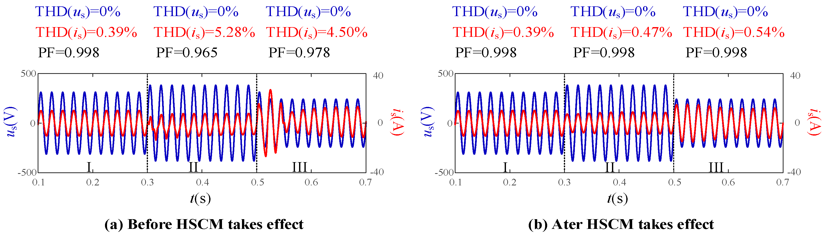
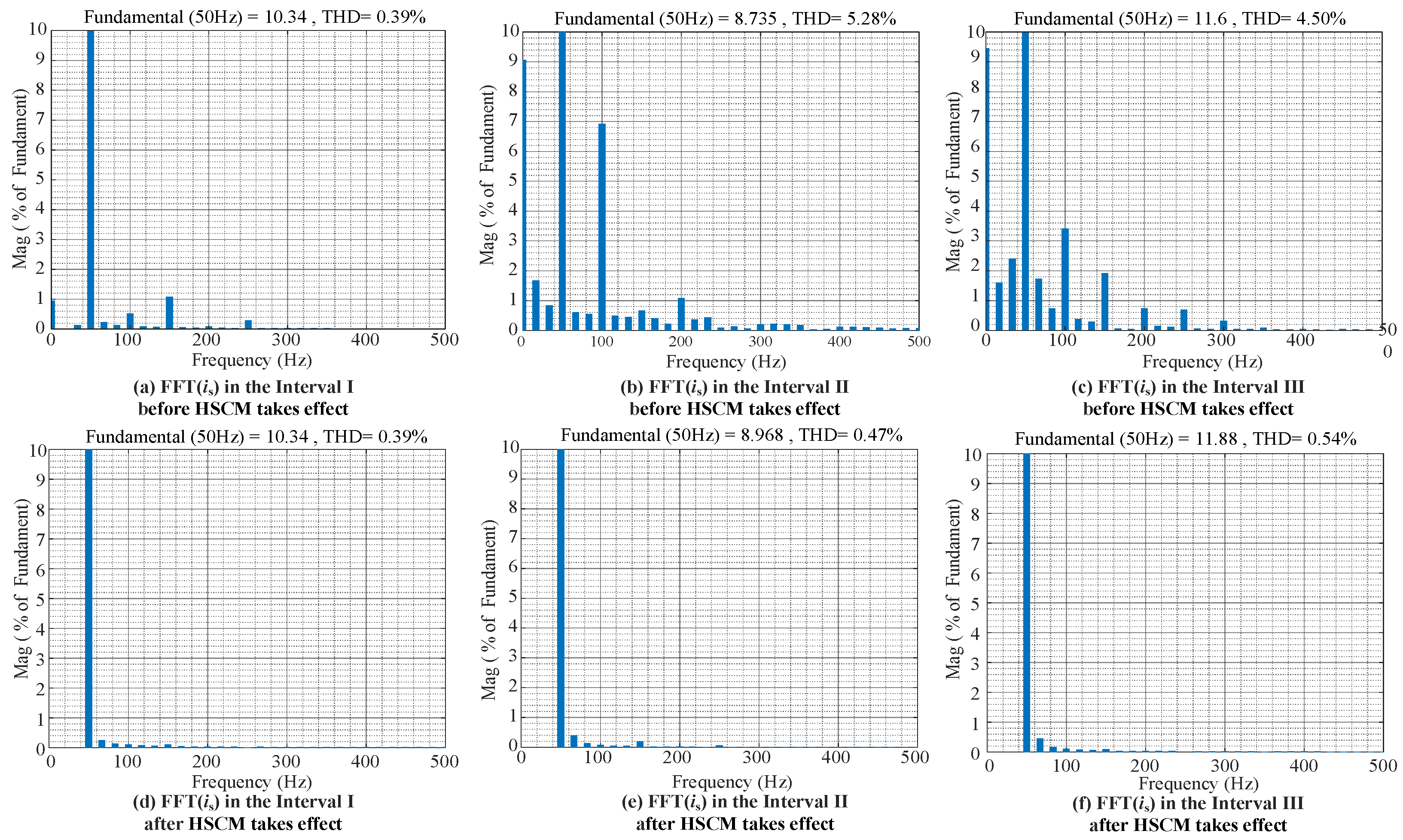
5. Simulation
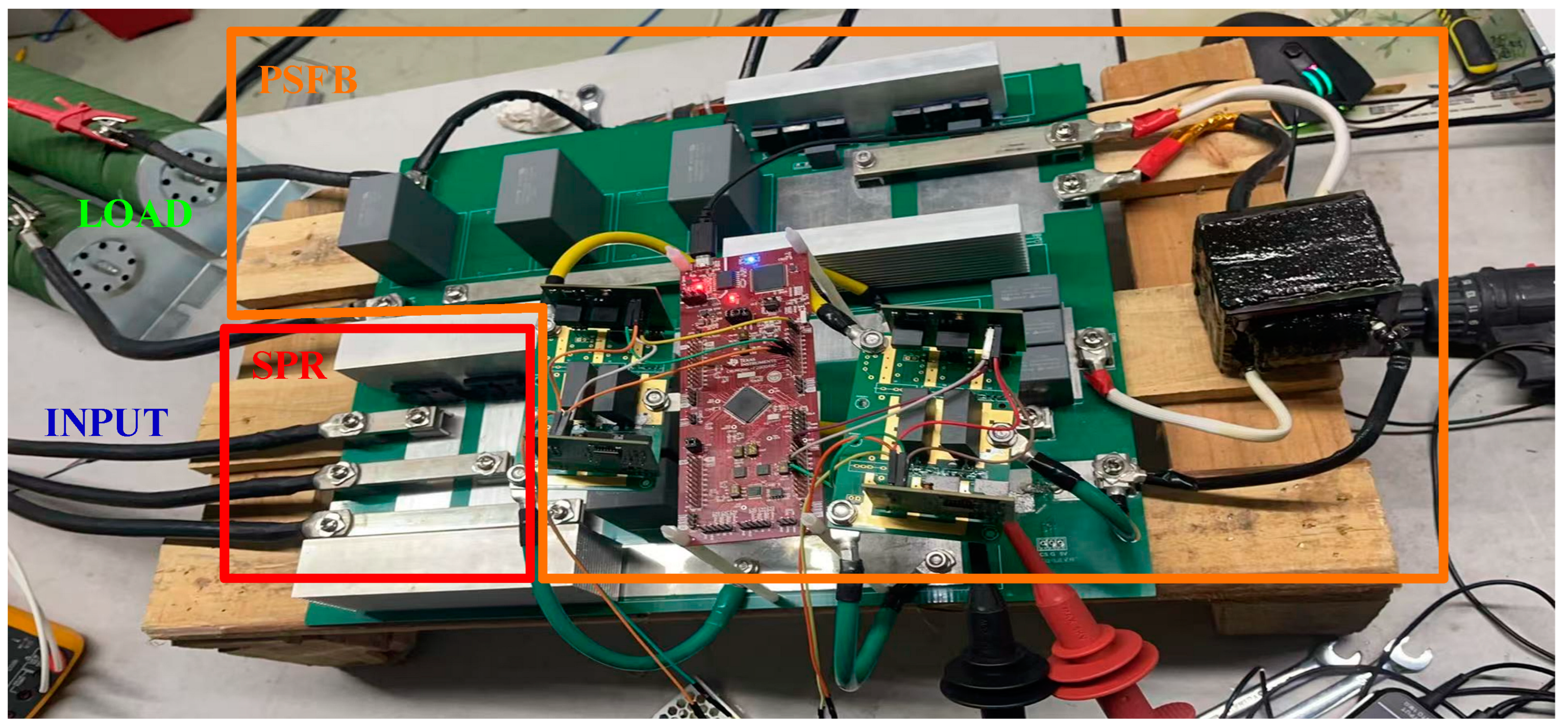
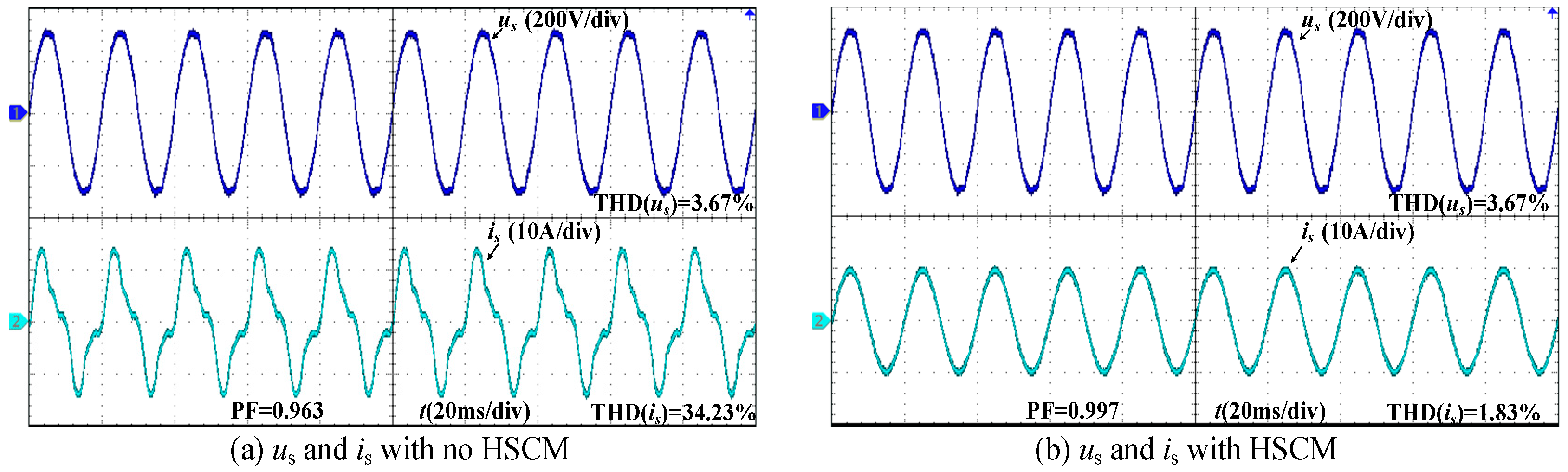
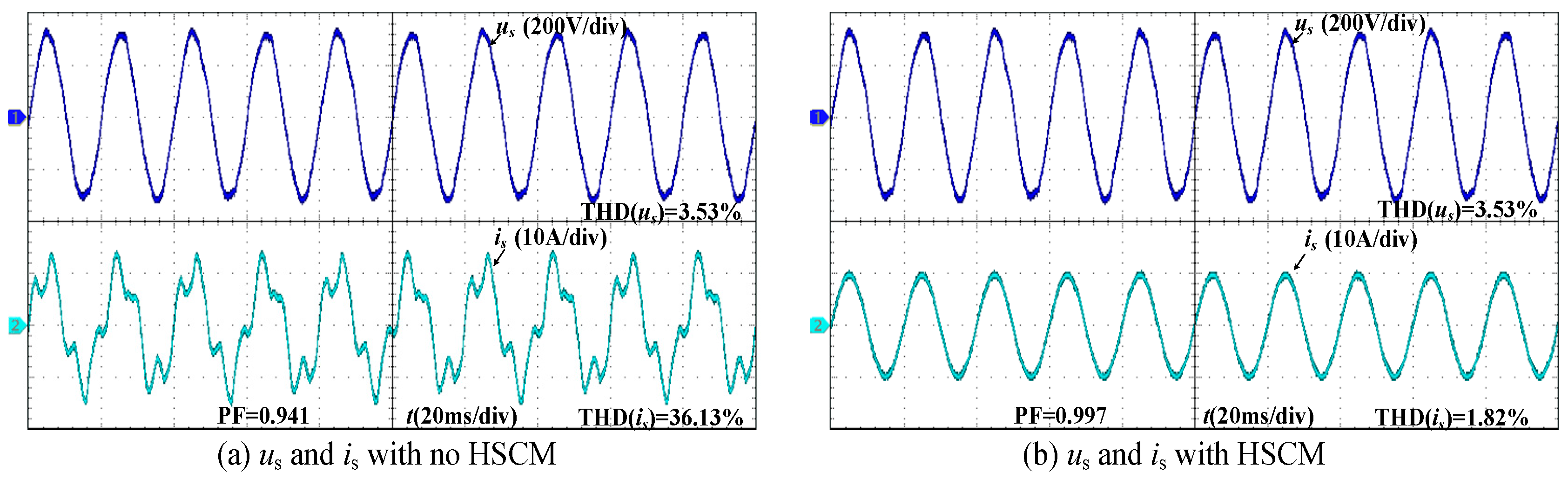
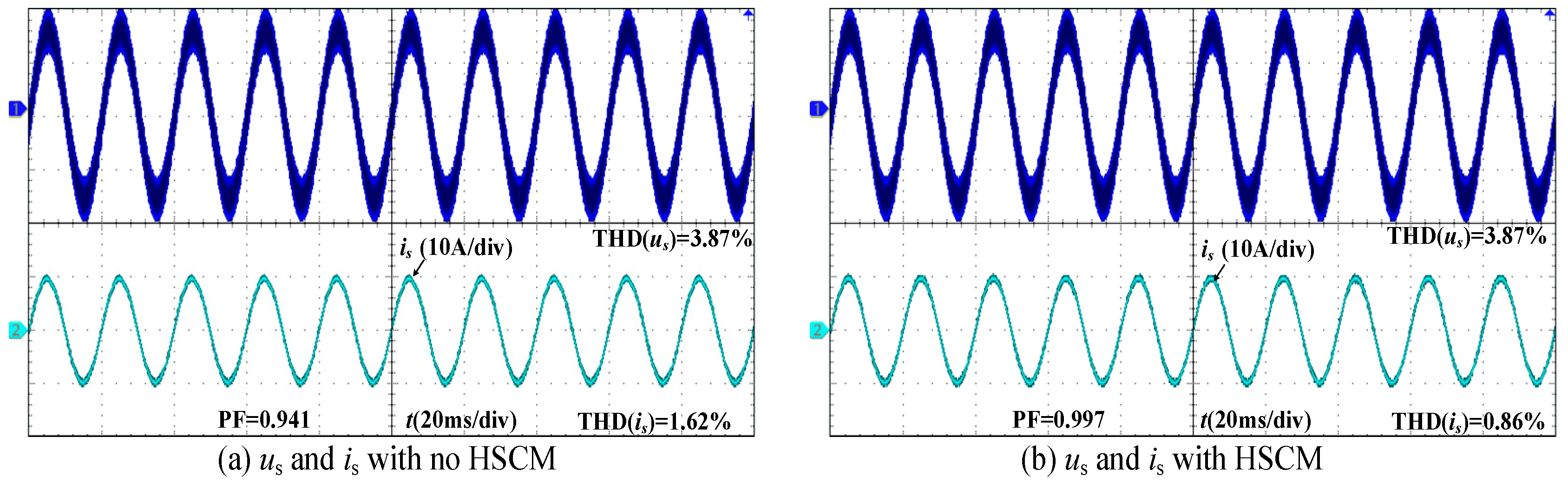
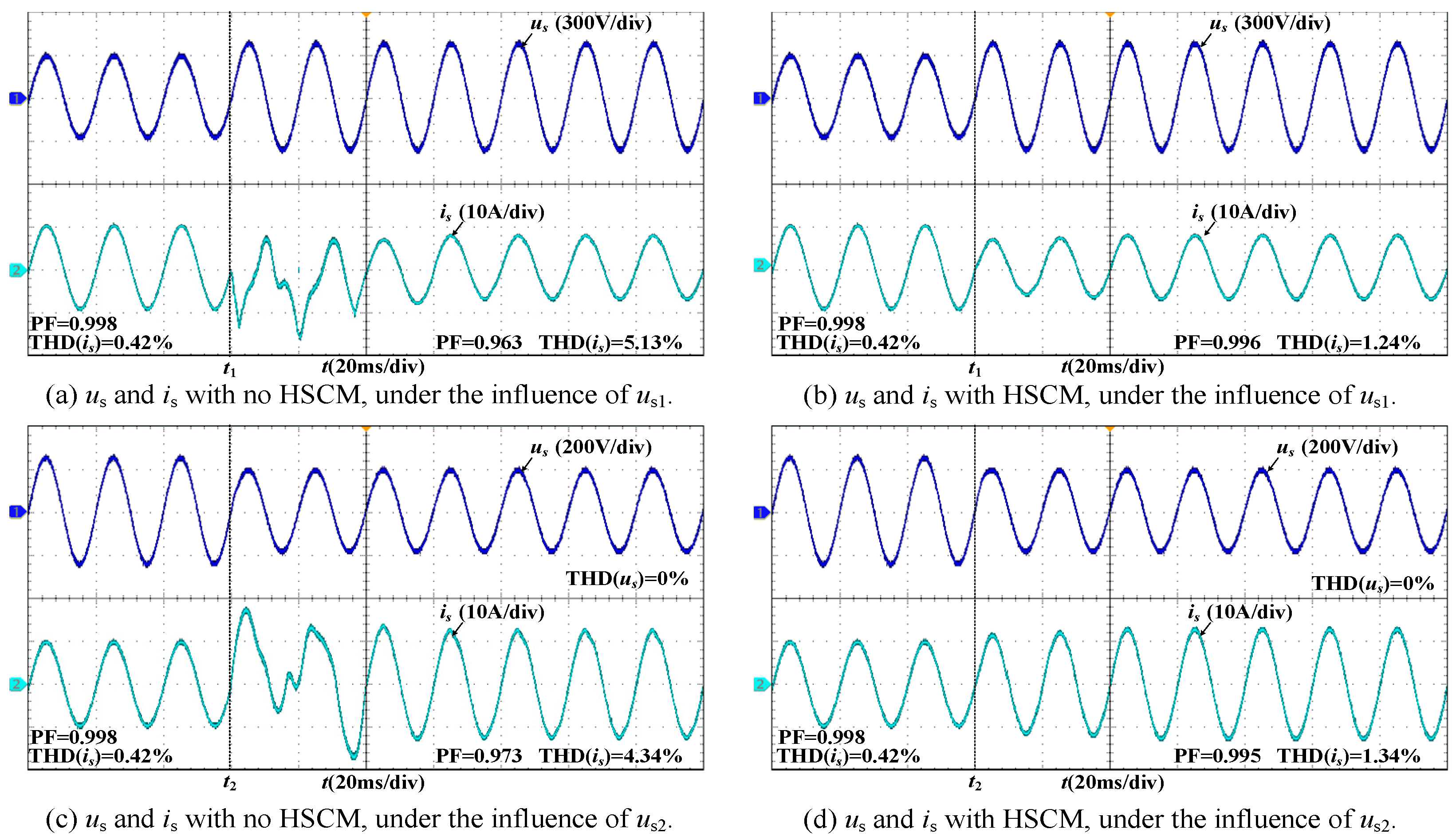
6. Experiment
7. Conclusions
Author Contributions
Funding
Data Availability Statement
Conflicts of Interest
References
- Meng, M.; Chen, M.; He, X.; Wang, J.; Liu, J. A Novel High Power Hybrid Rectifier with Low Cost and High Grid Current Quality for Improved Efficiency of Electrolytic Hydrogen Production. IEEE Trans. Power Electron. 2021, 37, 3763–3768. [Google Scholar]
- Kumar, K.; Samuel, P. Green Hydrogen Generation from the PEM Electrolyzer Powered by Solar Panel. In Proceedings of the Fifth International Conference on Electrical, Computer and Communication Technologies (ICECCT), Erode, India, 22–24 February 2023; pp. 1–6. [Google Scholar]
- Mabrak, H.; Elmazouzi, S.; Takky, D.; Naimi, Y.; Colak, I. Hydrogen Production by Water Electrolysis: Review. In Proceedings of the 12th International Conference on Renewable Energy Research and Applications (ICRERA), Oshawa, ON, Canada, 29 August–1 September 2023; pp. 372–380. [Google Scholar]
- Zeng, J.; Huang, Z.; Ling, Y.; Yang, L.; Li, Z.; Qiu, G.; Yang, B.; Yu, T. Analysis and hardware implementation of virtual resistance based PV inverters for harmonics suppression. IET Gener. Transm. Distrib. 2019, 13, 4592–4603. [Google Scholar]
- Liu, Q.; Li, Y.; Luo, L.; Peng, Y.; Cao, Y. Power Quality Management of PV Power Plant with Transformer Integrated Filtering Method. IEEE Trans. Power Deliv. 2019, 34, 941–949. [Google Scholar]
- Hari Prabhu, M.; Sundararaju, K. Power quality improvement of solar power plants in grid connected system using novel Resilient Direct Unbalanced Control (RDUC) technique. Microprocess. Microsyst. 2020, 75, 103016. [Google Scholar]
- Zhao, J.; Yang, H.; Pan, A.; Xu, F. An improved complex ICA based method for wind farm harmonic emission levels evaluation. Electr. Power Syst. Res. 2020, 179, 106105. [Google Scholar]
- Sowa, I.; Domínguez-García, J.; Gomis-Bellmunt, O. Impedance-based analysis of harmonic resonances in HVDC connected off shore wind power plants. Electr. Power Syst. Res. 2019, 166, 61–72. [Google Scholar]
- Ravikumar, S.; Vennila, H.; Deeepak, R. Hybrid power system with Total Harmonic Distortion minimization using improved Rider Optimization Algorithm: Analysis on converters. J. Power Sources 2020, 459, 228025. [Google Scholar]
- Blaabjerg, F.; Chen, Z.; Kjaer, S. Power electronics as efficient interface in dispersed power generation systems. IEEE Trans. Power Electron. 2004, 19, 1184–1194. [Google Scholar]
- Wang, L.; Han, Z.; Ning, C.; Dong, H.; Yao, X.; Ge, Y. Research on Photovoltaic Hydrogen Generation Microgrid Harmonic Suppression Method Based on Improved Virtual Synchronous Generator Control. In Proceedings of the 4th International Conference on Electrical Engineering and Control Technologies (CEECT), Virtual Conference, 17 December 2022; pp. 1020–1026. [Google Scholar]
- Tavakoli, S.D.; Dozein, M.G.; Lacerda, V.A.; Mañe, M.C.; Prieto-Araujo, E.; Mancarella, P.; Gomis-Bellmunt, O. Grid-Forming Services from Hydrogen Electrolyzers. IEEE Trans. Sustain. Energy 2023, 14, 2205–2219. [Google Scholar]
- Agbossou, K.; Kolhe, M.; Hamelin, J.; Bose, T.K. Performance of a stand-alone renewable energy system based on energy storage as hydrogen. IEEE Trans. Energy Convers. 2004, 19, 633–640. [Google Scholar]
- Najdi, R.A.; Shaban, T.G.; Mourad, M.J.; Karaki, S.H. Hydrogen Production and Filling of Fuel Cell Cars. In Proceedings of the 3rd International Conference on Advances in Computational Tools for Engineering Applications (ACTEA), Zouk Mosbeh, Lebanon, 13–15 July 2016; pp. 43–48. [Google Scholar]
- Hedayati, M.H.; John, V. Filter Configuration and PWM Method for Single-Phase Inverters with Reduced Conducted EMI Noise. IEEE Trans. Ind. 2014, 51, 3236–3243. [Google Scholar] [CrossRef]
- Qian, Q.; Xie, S.; Huang, L.; Xu, J.; Zhang, Z.; Zhang, B. Harmonic Suppression and Stability Enhancement for Parallel Multiple Grid-Connected Inverters Based on Passive Inverter Output Impedance. IEEE Trans. Ind. Electron. 2017, 64, 7587–7598. [Google Scholar] [CrossRef]
- Zhang, Y.; Zhou, S.; Li, B.; He, M.; Liu, G. A digital control strategy for three-phase PWM converter to suppress output voltage ripple under unbalanced input voltages. IEICE Electron. Express 2023, 20, 20230280. [Google Scholar]
- Cao, X.; Liu, X.; He, M.; Meng, X.; Zhou, Q. Active-Clamp Resonant Power Factor Correction Converter with Output Ripple Suppression. IEEE Access 2021, 9, 5260–5272. [Google Scholar]
- Liu, Y.; Wan, M.; He, Q.; Zhou, Q.; Meng, X. Buck-Type Single-Switch Integrated PFC Converter with Low Total Harmonic Distortion. IEEE Trans. Ind. Electron. 2020, 68, 6859–6870. [Google Scholar] [CrossRef]
- Javadi, A.; Al-Haddad, K. A Single-Phase Active Device for Power Quality Improvement of Electrified Transportation. IEEE Trans. Ind. Electron. 2015, 62, 3033–3041. [Google Scholar]
- Eroglu, H.; Cuce, E.; Mert Cuce, P.; Gul, F.; Iskenderoglu, A. Harmonic problems in renewable and sustainable energy systems: A comprehensive review. Sustain. Energy Technol. Assess. 2021, 49, 101566. [Google Scholar]
- Yang, Y.; Cao, W.; Su, Z. Harmonic Stability Analysis and Harmonic Suppression Strategy for Grid-Forming Converter with Dual-Loop Control. Sustain. Energy Technol. Assess. 2023, 49, 101566. [Google Scholar]
- Zeng, L.; He, X.; Han, P.; Wang, Y.; Wang, D.; Lin, J.; Zhao, H. Input and Output Harmonic Suppression Strategy of Single-Phase AC–DC–AC Converter. IEEE Trans. Ind. Electron. 2024, 71, 13042–13052. [Google Scholar]
- Yu, D.; Yi, H.; Zhang, H.; Jiang, X.; Zhang, Z.; Xie, Y. Suppression Method of Modulation Switching for the Inverter Oscillation caused by Harmonic Control. In Proceedings of the IEEE 4th China International Youth Conference on Electrical Engineering (CIYCEE), Chengdu, China, 12 August 2023; pp. 1–78. [Google Scholar]
- Sun, L.; Ding, J.; Han, Z. Suppression of Input Second Harmonic Current in Three-Stage Single-Phase Inverter based on PR Control. In Proceedings of the IEEE PELS Students and Young Professionals Symposium (SYPS), Shanghai, China, 27–29 August 2023; Volume 49, p. 101566. [Google Scholar]
- Chen, Y.; Chen, M.; Cai, H.; Hu, C. A Charging Current Ripple Suppression Strategy for Three-phase Power Conversion System Based on DC-side Harmonic Current Compensation. In Proceedings of the 25th European Conference on Power Electronics and Applications (EPE 23 ECCE Europe), Aalborg, Denmark, 4–8 September 2023; Volume 49, p. 101566. [Google Scholar]
- Zhao, M.; Ge, Q. Grid-Side Harmonic Current Suppression Based on Carrier Phase-Shifted PWM and Extended State Observer for High-Power Multiple Parallel 3L-ANPC Rectifier. IEEE Trans. Ind. Electron. 2024, 71, 5399–5410. [Google Scholar] [CrossRef]
- Li, G.; Shao, Y.; Liu, X. A Voltage Harmonic Self-Suppression Strategy of Single-Phase UPS. IEEE Trans. Ind. Electron. 2024, 71, 15685–15693. [Google Scholar] [CrossRef]
- Rong, S.; Xu, M.; Chen, X.; Liu, Z.; Su, H.; Li, H. Research on Optimal Virtual Impedance Harmonic Suppression Method for Grid-Connected Inverter. In Proceedings of the 8th Asia Conference on Power and Electrical Engineering (ACPEE), Tianjin, China, 14–16 April 2023; pp. 585–591. [Google Scholar]
- Liu, S.; Sun, Y.; Kang, Y. A Novel E-Exponential Stochastic Resonance Model and Weak Signal Detection Method for Steel Wire Rope. IEEE Trans. Ind. Electron. 2022, 69, 7428–7439. [Google Scholar] [CrossRef]
- Zhang, Y.; Wang, Z.; Wang, H.; Blaabjerg, F. Artificial Intelligence-Aided Thermal Model Considering Cross-Coupling Effects. IEEE Trans. Power Electron. 2020, 35, 9998–10002. [Google Scholar] [CrossRef]
- Li, Y.; Song, H.; Jiang, J. Vertical Ion-Coupling Ga2O3 TFT with Spatiotemporal Logic Encryption. IEEE Trans. Electron. Devices 2023, 70, 3122–3125. [Google Scholar] [CrossRef]


| Methods | Indicator a | Indicator b | Indicator c | Indicator d |
|---|---|---|---|---|
| The PI controller | × | √ | √ | × |
| The resonant elements controller | √ | √ | × | × |
| The QPR controller | × | √ | √ | × |
| The HSCM | √ | √ | √ | √ |
| Parameter | Value |
|---|---|
| us | cos(100πt)V |
| Ls | 1 mH |
| rs | 0.04 Ω |
| Ci | 470 μF |
| fs | 10 kHz |
| uo | 60 V |
| Pout | 1500 W |
| Ro | 2.4 Ω |
| Co | 220 uF |
| T | 2:1 |
| Cr | 10 uF |
| udc | 400 V |
| Harmonics | Value |
|---|---|
| Integer multiple harmonics | −0.0018cos(2ωt + 94.9°) − 0.0318cos(3ωt + 9.9°) −0.0035cos(4ωt + 92.9°) − 0.0023cos(5ωt − 64.1°) −0.0009cos(6ωt + 86.4°) − 0.0072cos(7ωt − 2.7°) −0.0016cos(8ωt + 26.3°) − 0.0098cos(9ωt + 110.1°) V |
| Interharmonics | −0.0018cos(2.5ωt + 94.9°) − 0.0318cos(3.5ωt + 9.9°) −0.0035cos(4.5ωt + 92.9°) − 0.0023cos(5.5ωt − 64.1°) −0.0009cos(6.5ωt + 86.4°) − 0.0072cos(7.5ωt − 2.7°) −0.0016cos(8.5ωt + 26.3°) − 0.0098cos(9.5ωt + 110.1°) V |
| Supraharmonics | −0.318cos(3500ωt + 9.9°) − 0.18cos(4500ωt + 94.9°) V |
| Parameter | Type | Number | Nrand |
|---|---|---|---|
| La,Lb,Lc | LGNE1 mH-30–100K-3P | 1 | LGNE |
| S1~S6 | IKW30N60T | 6 | Infineon |
| Ci | C3D1U206JF0BC00/20uF | 3 | Faratronic |
| S7~S10 | IKW30N60T | 4 | Infineon |
| Cr | C3D1U505KB00C00/5uF | 2 | Faratronic |
| T | GTF-60V 50A-100K | 1 | Wengudq |
| D1~D4 | VS-E5PH6006L-N3 | 4 | VISHAY |
| Lo | LGNE2uH-50–100K-CF3 | 1 | LGNE |
| Co | 450MXG470MEFCSN35X | 2 | Rubycon |
| us | 61815-TC | 1 | Chroma |
| Ro | ZX-5-2.4 | 1 | Tianjin Langwo |
Disclaimer/Publisher’s Note: The statements, opinions and data contained in all publications are solely those of the individual author(s) and contributor(s) and not of MDPI and/or the editor(s). MDPI and/or the editor(s) disclaim responsibility for any injury to people or property resulting from any ideas, methods, instructions or products referred to in the content. |
© 2025 by the authors. Licensee MDPI, Basel, Switzerland. This article is an open access article distributed under the terms and conditions of the Creative Commons Attribution (CC BY) license (https://creativecommons.org/licenses/by/4.0/).
Share and Cite
Lun, L.; Chen, S.; Zhan, Y.; Yang, H.; Zhu, J. A Harmonic Suppression Method for the Single Phase PWM Rectifier in the Hydrogen Production Power Supply. Appl. Sci. 2025, 15, 3978. https://doi.org/10.3390/app15073978
Lun L, Chen S, Zhan Y, Yang H, Zhu J. A Harmonic Suppression Method for the Single Phase PWM Rectifier in the Hydrogen Production Power Supply. Applied Sciences. 2025; 15(7):3978. https://doi.org/10.3390/app15073978
Chicago/Turabian StyleLun, Li, Siming Chen, Yihe Zhan, Hui Yang, and Jianyong Zhu. 2025. "A Harmonic Suppression Method for the Single Phase PWM Rectifier in the Hydrogen Production Power Supply" Applied Sciences 15, no. 7: 3978. https://doi.org/10.3390/app15073978
APA StyleLun, L., Chen, S., Zhan, Y., Yang, H., & Zhu, J. (2025). A Harmonic Suppression Method for the Single Phase PWM Rectifier in the Hydrogen Production Power Supply. Applied Sciences, 15(7), 3978. https://doi.org/10.3390/app15073978