Abstract
Verification of geometrically complex components is a crucial step in ensuring the quality and functionality of industrial products. This article presents a comprehensive methodological approach to their verification using reverse engineering techniques. The study highlights the limitations of traditional measurement methods for complex geometries and proposes a framework that integrates advanced 3D scanning and digital modeling. The methodology involves obtaining accurate geometric data, with deviations during repeated measurements being well within the tolerance range. With a tolerance of ±1 mm, the maximum deviation was −0.66 mm, while the maximum deviation with the highest tolerance of 4.5 mm was 1.19 mm. These data were compared with predefined 3D models to analyze deviations and identify process errors. By applying this detailed methodology, more precise fixtures were created, resulting in measurements with deviations well below the required tolerances, compared to measurements without this methodology. A practical example of the design and verification of a welding fixture for cabin manufacturing illustrates the effectiveness of reverse engineering in detecting inconsistencies and optimizing manufacturing processes. The findings emphasize the importance of geometric accuracy in quality control and demonstrate how reverse engineering can streamline verification processes and enhance product reliability. This approach is particularly valuable for the manufacturing industry, which requires high precision in the production of geometrically complex components.
1. Introduction
Currently, the verification of geometric components in industrial applications primarily relies on traditional measurement methods, such as coordinate measuring machines (CMMs) and manual measurements. While these techniques are effective for assessing basic geometric shapes, they encounter limitations when applied to complex geometries with minor deviations. Traditional methods can be time-consuming and prone to human error, ultimately affecting measurement accuracy and the overall quality of the components [1,2,3,4]. With advancements in reverse engineering technologies, more efficient and precise verification of complex components, including welded structures, has become possible. Reverse engineering involves analyzing an existing product or component to understand its design, function, and parameters. It is widely used in manufacturing, quality control, digitalization, and metrology. The process consists of digitizing an object through 3D scanning, processing the acquired data, reconstructing a CAD model, and validating its accuracy. Three-dimensional scanners enable the capture of highly detailed geometric data, facilitating the creation of digital models that can be compared against predefined CAD specifications. This approach provides precise measurements and an in-depth deviation analysis between scanned data and original models, allowing for the identification of potential manufacturing defects, welding-induced deformations, and optimization of production processes. Consequently, reverse engineering enhances the ability to swiftly detect inconsistencies, contributing to improved quality and reliability of welded components.
Similar challenges in component verification and the application of reverse engineering have been explored in previous research. The study conducted by Li. et al. examines a reverse engineering approach to facilitate the remanufacturing of worn mechanical components with uncontrolled failure conditions and complex geometries. The research outlines a methodology that includes 3D surface data acquisition, nominal model reconstruction, precise registration, defect extraction, tool path generation, and machining processes. A Prominent Cross-Section algorithm with curvature constraints is employed to identify damaged areas and exclude defective point clouds during reconstruction. Additionally, an improved Iterative Closest Point (ICP) algorithm integrates curvature and distance constraints to achieve optimal alignment between worn and nominal models. The study concludes with the successful remanufacturing of mechanical components [5].
R. Helle and his team also addressed this topic by examining the application of reverse-engineering-based 3D scanning technologies for quality control. Their study involved scanning a 3D-printed component with a complex geometry using a laser scanner. Two surface modeling techniques were tested: the primitive-based method, suitable for manufacturing, and NURBS modeling, which provided a more accurate surface representation. The research confirmed the suitability of 3D scanning for complex shapes while emphasizing the need to improve the efficiency and accuracy of reconstruction methods [6]. Furthermore, the study by Liu X. et al. focuses on the analysis of residual deformations occurring during the resistance spot welding (RSW) process on a basic structural panel (BSP), which was designed using reverse engineering and finite element analysis (FEA) simulations. Here, reverse engineering was employed to compare the original and final geometries of the panel to determine the overall residual deformation, highlighting the interaction of deformations across multiple welding processes [7].
P. Ruediger et al. investigated the use of visualization and machine learning for analyzing parameters influencing manufacturing quality. Their reverse-engineering-based approach identifies key parameters and their impact on parts using dimensionality reduction. The prototype system enables the determination of optimal settings for quality control, which the authors validated through a sheet metal deformation example [8].
Katsuhiro Saiga and colleagues present a sustainable approach to reverse engineering that minimizes the need for sophisticated technologies. Their five-step methodology—from geometric modeling to 3D printing—accelerates the process while maintaining accuracy. This approach supports sustainable product development and production optimization [9].
The reason for conducting this research was the need to address the issue of cabin deformations that occurred during the initial welding phase when the cabin was welded. This approach led to deformations caused by the weight of the structure and handling of components, which negatively affected the accuracy of the final products. Therefore, the welding process was divided into several parts, with the key factor being the dimensional stability of the smaller parts of the cabin, aimed at eliminating inaccuracies during assembly and ensuring the accuracy of the overall product.
This research addresses the limited accuracy of traditional measurement methods for inspecting complex components and the lack of standardized procedures for verifying welding fixtures using reverse engineering. While existing literature covers 3D scanning and digital reconstruction, it lacks a systematic methodology for welding processes to quantify accuracy and effectiveness. The study aims to develop a methodology for verifying welding fixtures with 3D scanning and deviation analysis, compare it with traditional methods, and identify key factors affecting measurement accuracy and quality control. This work fills a gap in the existing literature and highlights the practical benefits of reverse engineering in manufacturing optimization.
2. Materials and Methods
The research focused on designing a geometrically complex welding fixture intended for the assembly of a specific cabin structure (front panel). The primary objective was to develop a fixture that would ensure stability and precision during the welding of sheet metal components, minimizing geometric inaccuracies and deformations caused by heat input during the process. The methodological approach emphasized the detailed design of the fixture, which underwent thorough verification and analysis to ensure its effectiveness in real manufacturing conditions.
The fixture design was carried out using advanced CAD software tools, considering all factors affecting welding accuracy as well as the specific characteristics of individual cabin components. Following the conceptual design, a verification process was conducted, which included testing and measuring geometric deviations occurring during welding. This research thus aimed to optimize manufacturing processes and eliminate potential errors in geometric parameters, thereby enhancing the overall quality and reliability of the final product.
During the assembly of the cabin, which consists of welded complex components, geometric inaccuracies, and deformations arose due to heat input during welding, improper handling of semi-finished products, and material processing errors such as bending and curvature. These inaccuracies affected the final quality and functionality of the cabin, as deviations from dimensional accuracy requirements led to assembly issues or incorrect positioning of components. The solution to this problem was the design of an effective welding fixture that ensured stability and precision during welding, which was verified using reverse engineering. Until now, quality control has mainly relied on visual assessment and manual measurements, which do not provide sufficient accuracy for detecting minor yet critical geometric defects. This situation underscores the necessity for a new, more precise system for monitoring geometric errors during welding.
This research was based on a comprehensive methodology that incorporated several key steps and the use of specific technologies and tools to ensure the precision and quality of welding processes:
- Identification of the primary issue, which was ensuring geometric accuracy during the welding of cabin sheet metal components.
- Review of the current state of welding fixtures and verification of geometric parameters.
- Consideration of the specific geometric shapes of the cabin and the design of a fixture tailored to these components.
- Development of a geometrically complex welding fixture aimed at minimizing deformations and deviations of components during welding, utilizing Creo PTC software (version 11.0.0.0).
- Design of a welding fixture prototype incorporating input parameters, including material selection (steel S235JR–1.0038) and the chosen welding technology (MAG).
- Manufacturing the fixture with a focus on dimensional accuracy in positioning semi-finished products (locks, engraving).
- Application of the 3D scanner Kreon ACE-7-30 (Kreon company, Limoges, France) and the PolyWorks Inspector Standard software (version 2022) for data collection, measurement of geometric deviations of welded components (fixture), and analysis against digital reference data. Measurement results were compared with predefined tolerances to assess the fixture’s effectiveness in minimizing errors.
- Evaluation of results in terms of deviation acceptability within established tolerances, allowing for an objective assessment of the fixture’s efficiency.
- Presentation of test results and evaluation of the design’s performance.
- Discussion of potential process improvements and methods for achieving more precise component positioning and optimization of the welding process.
- Formulation of conclusions regarding the effectiveness of the proposed welding fixture in optimizing the production process. Recommendations for further improvements in fixture design and measurement technologies, which could enhance manufacturing accuracy in the future, along with continued research on additional components.
2.1. Identification of Critical Factors Affecting Accuracy
The dimensional accuracy of cabin weldments is a crucial factor influencing their functionality, assembly, and overall quality. Dimensional inconsistencies arise due to multiple critical factors that impact various stages of the manufacturing process. The most common causes include inconsistent quality of input semi-finished products, thermal deformations during welding, inaccuracies in welding fixtures, and improperly configured welding parameters. In the case of complex structures, these errors may become irreparable, meaning that inaccuracies in individual components can have a significant impact on the final product and lead to costly rework or rejection. Even minor geometric deviations can cause substantial issues during assembly, such as misalignment of parts, restricted functionality of moving components, or a reduction in the aesthetic quality of the final product [10,11].
In the production of complex structures such as cabins, even small dimensional and geometric deviations can accumulate over time, leading to significant overall defects and affecting the quality of the final product. These deviations can occur during various stages of production and material processing, significantly impacting the precision and proper functioning of the final assembly process.
Figure 1 illustrates a welded cabin structure where dimensional deviations arise due to several potential factors. One of the main causes is errors in the processing technology, such as laser cutting or material bending. Although these technologies are highly precise, they can sometimes cause minor material deformations, which later manifest as deviations in the final dimensions of the parts. Additionally, defects in the semi-finished products, such as waves, bumps, or incorrectly cut sections, may also cause deviations that accumulate and affect the quality of the final structure. A visible misalignment in the joint precision, which appears as an evident deviation between the joined parts, causes improper fitting of individual components. These misaligned joints later reflect in incorrect assembly, where components that should fit together do not match precisely, complicating the subsequent assembly phase. This leads to problems when joining individual cabin parts, which may result in irregular seating or improper connections between different parts of the structure. These issues often require additional adjustments or repairs, which can significantly extend production time and increase costs.
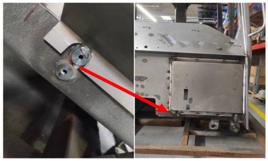
Figure 1.
Shows dimensional and shape deviations in a cabin structure due to processing errors, material defects, and thermal deformations during welding, causing assembly issues.
One of the primary challenges in geometrically complex components is thermal deformation, which occurs due to uneven heating and cooling of the material. This phenomenon causes shrinkage, displacement, and warping of parts, leading to deviations from the required dimensions. Another critical factor is the quality of semi-finished materials, where material inhomogeneity and residual stress contribute to deformations even in the initial phases of the process [12].
Improperly designed or worn-out welding fixtures can negatively affect the correct positioning of components, increasing the likelihood of dimensional errors. Similarly, incorrect welding parameter settings—such as welding speed, current, or voltage—can result in poor-quality weld joints and uneven stress distribution within the material. To mitigate these issues, thorough process planning, optimization, and the implementation of appropriate control mechanisms are essential. The use of simulation tools allows for the prediction and minimization of thermal deformations already in the design phase. Additionally, regular quality control of input materials, calibration of fixtures, and personnel training play a crucial role. The proper identification and resolution of these critical factors are fundamental to achieving the required accuracy of cabin weldments and ensuring long-term reliability [13,14].
To verify the deficiency illustrated in Figure 1, a reverse engineering method was employed, providing a detailed and precise assessment of geometric deviations between the actual weldment and its digital 3D model. Following an initial visual inspection, which can reveal fundamental defects, the weldment was measured using advanced reverse engineering technology. These devices enable accurate geometry capture, allowing the obtained values to be compared against the original CAD model. In this study, a Kreon ACE-7–30 articulated-arm 3D scanner was selected, capable of detecting even the smallest geometric deviations with high precision, ensuring that any discrepancies affecting assembly quality and accuracy are identified [15,16].
The scanner was certified for a reach of 3000 mm, meaning it can perform measurements at distances up to this value with high precision. This certification is essential as it ensures that the device meets the quality and measurement reliability requirements set by the relevant standards and regulations. The verification results of its reliability can be seen in Table 1 [17].

Table 1.
Technical specifications of the Kreon ACE-7-30 scanner.
This process of comparing the measured parameters with the 3D model provides detailed information on any deviations that may result from improper welding fixture settings, thermal deformations of the material, or insufficiently precise welding parameter adjustments. These deviations may manifest as dimensional errors, which could affect subsequent assembly or the functional integrity of the weldment within the assembly. By identifying and quantifying these deviations, it is possible to determine precisely which aspects of the manufacturing process require adjustment, whether it involves modifying welding parameters, optimizing fixtures, or refining production processes. Reverse engineering thus not only confirms the existence of deficiencies but also provides specific data to improve the manufacturing process and minimize errors [18,19].
To improve access to the measured surfaces of the cabin weldment and optimize scanning angles, an elevated platform, as shown in Figure 2, was used. This setup ensured better visibility and reduced obstacles during the measurement process. Positioning the weldment at a more accessible height allowed for easier and more precise scanning of complex areas. The elevated platform also helped minimize potential errors from poor scanning angles, ultimately improving the accuracy and reliability of the measurements. This approach contributed to more efficient data collection and enhanced the overall quality of the inspection process.
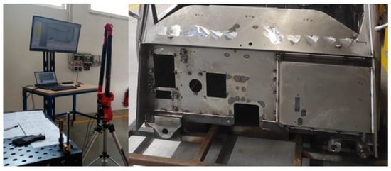
Figure 2.
Illustration of the measured object and scanning equipment setup for optimal access to the surfaces of the cabin weldment.
As shown in Figure 3, which displays the color deviation map, the inspection process involves selecting input values—specifically, the permissible tolerances based on the technical drawing documentation (in our case, ±6 mm). These values are represented in green on the map, indicating that the measured deviations fall within acceptable limits. Blue areas on the map denote negative deviations, meaning that the measured point is below the required value. Conversely, red areas indicate positive deviations, signifying that the measured point exceeds the specified dimensional requirements.
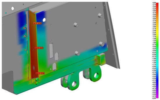
Figure 3.
The graphical representation shows weldment deviations, with green indicating acceptable limits, blue for negative deviations, and red for exceedances, helping to identify areas needing adjustment.
If the overall model exhibits deviations in red or blue areas that exceed the allowed tolerances, it indicates that the model is defective and requires adjustments or corrections in the manufacturing process to achieve the required precision and quality.
2.2. Factors Influencing Geometric Accuracy and Quality
Deficiencies in technological processes can arise for various reasons, with the most common factors including inappropriate production parameters, material properties, the quality of input semi-finished products, and the influence of external environmental conditions. These errors can lead to a reduction in the quality of final products, affect their mechanical properties, and ultimately cause non-conformities in assembly processes. When processing metal components, particularly sheet metal parts, it is essential to precisely monitor each step of the manufacturing process to minimize deviations and defects that may occur during bending, cutting, or welding.
One of the key areas where defects occur is the welding process, as highlighted by the red circles in Figure 4. These defects can arise due to several factors, such as improper welding parameters (e.g., incorrect heat settings, inadequate welding speed, or unsuitable filler materials), insufficient control over the welding environment (e.g., drafts or fluctuating ambient temperature), or even operator errors. Such defects can result in issues like warping, cracking, or porosity in the weld, all of which compromise the structural integrity and dimensional accuracy of the welded components. These welding-related deficiencies often require rework or corrections, increasing production time and costs [20,21].
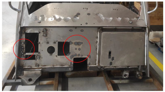
Figure 4.
The front panel of the cabin showing thermal zones where welding-induced temperature variations cause dimensional deviations.
During welding, significant thermal changes take place in the material, leading to the formation of the heat-affected zone (HAZ). This zone is critical because its properties differ from those of the unwelded material due to localized heating and subsequent cooling. Incorrect welding parameter settings, such as welding current or welding speed, can cause undesirable structural changes in the material, resulting in cracking or warping [22].
In the detailed view in Figure 5, the heat-affected zone forms in different locations depending on the welding process, joint type, and applied parameters. This zone is situated near the weld metal itself, where significant microstructural changes occur due to thermal exposure. This phenomenon is particularly critical in thin sheet metals, where excessive heat input can lead to overheating and unwanted deformation after cooling [23].
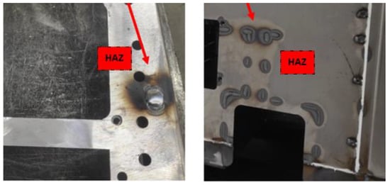
Figure 5.
Heat-affected zones near the weld can alter material properties, impacting the structural integrity of the cabin weldment.
In the processing of sheet metal components, errors may also arise due to incorrect bending, where improper machine settings or inappropriate tool selection lead to deviations in angles and dimensions. These errors can significantly affect subsequent welding operations, as improperly prepared parts may not fit together precisely, resulting in increased weld gaps and reduced joint strength [24].
Additionally, improper material handling can cause surface defects, which later impact the final quality of the welded joint. As shown in Figure 6, properly bent components are correctly positioned, ensuring precise alignment. The correct bend position guarantees perfect contact between parts, minimizing the occurrence of thermal deformations in the welding area and ensuring high weld quality.
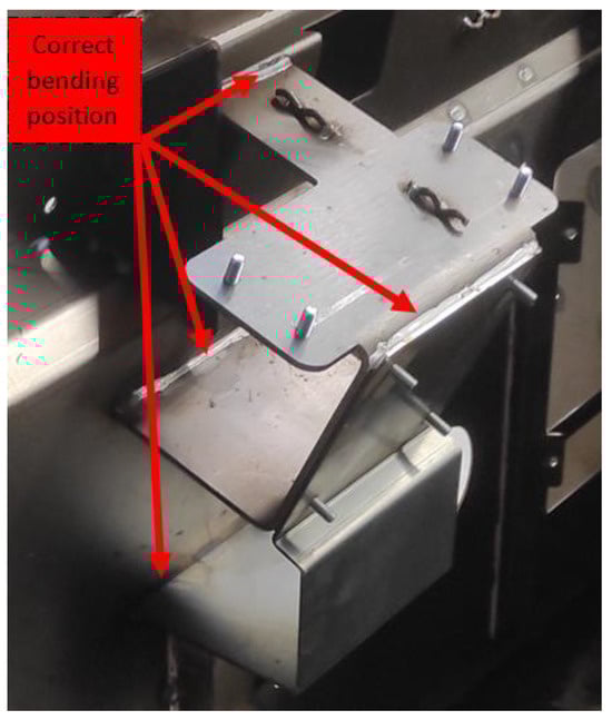
Figure 6.
Detail of the correct bending and positioning of sheet metal components on the cabin.
2.3. Errors in the Design and Wear of Welding Fixtures and Their Impact on the Accuracy of Component Positioning
Welding fixtures are devices or tools used to hold and position parts during welding to ensure their correct orientation and alignment. The design of a welding fixture involves various steps and considerations to guarantee precise and efficient welding. Improperly designed or worn-out welding fixtures can cause significant issues affecting the overall quality and accuracy of welds. If the fixture does not provide adequate clamping of the components, they may experience undesired movement during welding. This can lead to displacement, rotation, or oscillation of the parts, increasing the probability of defects such as misalignment, deformations, or incorrect weld geometry.
A key aspect of fixture design is the proper placement of clamping points. Incorrect positioning can cause uneven material stress during welding, leading to distortions. For example, if the clamping points are placed too close together, excessive stress may be concentrated in certain areas, potentially causing positional shifts, which are critical for complex structures. Worn-out or damaged clamping mechanisms can result in improper component fixation, allowing movement during welding. If the contact surfaces of the fixture are worn or contaminated, stability and positioning may be compromised. Dirt and wear can reduce positioning accuracy and lead to instability during welding. Over prolonged use, geometric deviations or reduced stiffness may develop in the fixture. If a welding fixture consists of multiple components, ensuring proper assembly is crucial to keeping parts in the correct position throughout the welding process. To facilitate accurate component placement, the use of locks or engraved markings is essential, aiding in the proper alignment of individual fixture elements [25,26]. Minimizing welding processes and utilizing cold joints is an effective strategy to reduce deformations and enhance part accuracy, particularly for thinner materials. In thin sheet metal components, welding is more prone to thermal deformations, which can affect shape and geometric accuracy. On the other hand, welding thicker plates is generally easier, as the material withstands high temperatures better and results in stronger welds. However, thicker plates increase the overall weight of the fixture and make handling more challenging [27].
One effective approach to minimizing welding-induced deformations is to divide larger welded assemblies into smaller sections. This process offers several advantages. Smaller parts welded separately are less prone to deformation, as thermal effects act on a smaller volume of material. By gradually joining these parts into larger assemblies, geometric accuracy can be better controlled, preventing major shape alterations. This approach also simplifies fixture design, reducing both costs and setup time. Additionally, each subassembly can be individually inspected for quality and accuracy, allowing for the early detection and correction of potential issues [28].
An overview of the design factors of the welding fixture is presented in Table 2, which highlights the key categories and their respective elements. These factors are critical for ensuring the proper functioning, accuracy, and safety of the welding fixture, including aspects such as geometric and dimensional requirements, material selection, type of welding, fixture adjustability, and safety measures. Proper consideration of these factors during the design phase ensures the fixture meets the necessary technical specifications and performs reliably across different applications [29,30].
Table 2.
Comprehensive view of the design factors of the welding fixture.
The prototype of the rotary welding fixture, shown in Figure 7, was designed based on the digital model of the front panel of the cabin (yellow model) and is engineered to ensure precise and stable fixation of components during the welding process. The parts are secured within the fixture using various clamping elements, such as mechanical clamps, toggle clamps, and stops, which keep the individual components in the required position throughout the entire welding operation. This fixture is equipped with a rotary mechanism that allows rotation around its axis, providing flexibility for welding from different angles. Rotational functionality eliminates the need for repositioning and excessive handling, thereby increasing the efficiency and accuracy of the welding process.
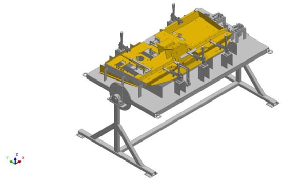
Figure 7.
Prototype of the rotating welding fixture structure.
The fixture’s structure was built using various types of profiles and sheet metal components, which were processed using laser cutting technology. This method ensures high precision and machining quality, which is essential for achieving the required technical parameters and geometric accuracy of the components. To guarantee the precise positioning of individual fixture elements, locks integrated into the base plate were implemented. These locks enable consistent and repeatable positioning, eliminating potential assembly errors. The design also included engraving (mechanical marking), which serves to identify positions or key reference points, facilitating easier orientation during fixture assembly and improving the overall efficiency of the work process. The combination of locks and engravings ensured high positioning accuracy while minimizing assembly deviations. For certain fastened components, such as clamps, a mechanical joint method was chosen. This approach was selected to minimize the risk of deformations that could occur during the welding process while also allowing for easy disassembly in case of a mechanism failure. The use of bolted joints enables simple replacement or repair of damaged parts without requiring complex technological interventions.
Finally, casters were mounted on the bottom section of the fixture, facilitating easier movement and handling during transportation.
2.4. Manufacturing of the Prototype and Processes Related to Welding, Assembly, and Surface Treatment
During the manufacturing of the prototype welding fixture, several key phases were followed to ensure the precision and functionality of the final product. To prevent potential bending errors and achieve the required accuracy in the production of the welding fixture, a specific methodology was chosen, focusing on precise processing and component assembly.
No materials requiring subsequent bending were used in the manufacturing process; instead, laser-cut parts were employed. This production method enabled high accuracy, minimizing geometric deviations and ensuring a quick alignment of individual components during assembly. The components that were later assembled into the welding fixture were designed with interlocking features, ensuring precise geometric accuracy during assembly while reducing the risk of assembly errors. These interlocks acted as positioning guides, ensuring the correct placement of components, thereby eliminating the risk of misalignment.
After welding, toggle clamps and positioning stops were added to the fixture to provide stability, correct positioning, and accuracy throughout the entire welding process. For quick assembly and potential adjustments after prolonged use, these elements were fastened using bolted joints. This fastening method was selected for its flexibility and precision, allowing for the fine-tuned positioning of individual components to achieve the stability and accuracy necessary for proper part alignment.
Furthermore, during the fixture design phase, particular emphasis was placed on minimizing thermal defects in the heat-affected zone (HAZ), which could later impact the quality of the weld. By ensuring precise and stable fixation of components, the risk of material deformation during welding—caused by improper clamping or excessive heat input—was effectively eliminated. As can be seen in Figure 8, this approach resulted in a high-quality and precise outcome, fully prepared for the subsequent production stages.
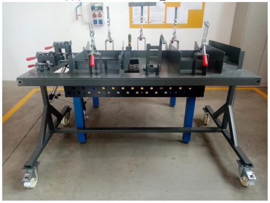
Figure 8.
Manufactured prototype of the welding fixture.
During verification, sheets of various thicknesses, ranging from 4 to 5 mm, were used, and welding was carried out using the MAG (Metal Active Gas) method. During the process, it was necessary to minimize thermal effects that could lead to deformation or excessive internal stress.
The first step was to properly clamp the sheets to prevent movement during welding. Initially, tack welding was performed at regular intervals, which fixed the material in the desired position and reduced twisting during the later application of the main weld.
When welding larger parts or joining sheets of different thicknesses, we selected procedures that ensured an even distribution of heat. Instead of welding in a single line, we applied a backstep welding procedure, where welds were placed in the opposite direction to prevent heat from concentrating in one area. This prevented excessive elongation of the material in one direction and minimized twisting.
An important factor was also controlling the heat input. We used a welding wire with a diameter of 1.0 mm, suitable for sheet thicknesses in the range of 4 to 5 mm, and worked with a welding current of 140 to 180 A and a voltage of 18 to 22 V. The average wire feed speed was 6 to 9 m/min, ensuring a stable melting process and optimal penetration of the weld metal into the base material.
To protect the welding area from oxidation and contamination, a mixture of protective gases, CO2 and Ar, was used, with a higher CO2 content (approximately 18 to 25%) supporting good penetration of the weld metal and a stable electric arc. Short breaks were made between individual welds to allow the material to cool naturally and prevent excessive heat buildup.
Finally, the fixture underwent surface treatment, specifically coating and painting, to protect it from external influences such as corrosion, scratches, and chemical exposure. The paint coating not only improved the fixture’s aesthetic appearance but also significantly increased its durability, which was essential for its long-term use in real industrial conditions.
2.5. Verification of the Welding Fixture Using the Kreon ACE-7-30 Scanner in PolyWorks Inspector
Before the welding fixture was introduced into serial production, a comprehensive verification process was conducted to ensure its accuracy and functionality. This step was essential to confirm that the fixture correctly positions individual components during manufacturing and meets the precision and tolerance requirements specified in the technical drawings. The primary objective was to identify any deviations that could affect manufacturing quality, particularly concerning locking mechanisms, clamps, and other key fixture components. To achieve this, reverse engineering techniques were employed, allowing for a detailed geometric analysis of the fixture. In this case, reverse engineering was used to verify whether the shape and dimensions of the fixture corresponded to the original CAD models. This process involved 3D scanning, which provided a digital representation of the fixture’s actual state. Subsequent analysis helped identify potential inaccuracies in the fixture’s construction, which could cause issues in serial production. This approach effectively mitigated risks such as incorrect part positioning or misalignment, which could lead to increased production costs, reduced product quality, or even fixture failure in operation.
During the scanning process, environmental factors that could affect measurement accuracy were considered. The lighting was stabilized to minimize its impact on scanning accuracy, as different lighting conditions can influence the quality of the captured data. Additionally, the surface properties of the object were considered during measurement. Surfaces with high gloss or reflectivity can cause inaccuracies, so specific scanner settings were applied to compensate for these factors and improve the scanning quality. The use of a calibrated scanner also played a crucial role.
To ensure the reliability and repeatability of the scanning process, the measurement was conducted in the same environment, where external influences such as temperature changes and vibrations were minimized. A stable table was used for the measurement, ensuring stability and eliminating any external movements that could affect accuracy. The repeatability of the measurement was verified by performing multiple scans of the same object, and the results were compared with reference values.
The entire verification process of the welding fixture was carried out using PolyWorks Inspector software, version 2022 (Figure 9), which is equipped with advanced tools for 3D scanning and geometric deviation analysis. This software is ideal for detecting inaccuracies and comparing the actual condition of the fixture with the specifications outlined in the technical documentation.
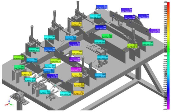
Figure 9.
Imported 3D model of the fixture with a tolerance color map showing deviations from nominal dimensions and a color scale.
Figure 9 illustrates the selection of all analyzed parts of the fixture, with clearly marked areas where deviations or critical geometric features were identified. The analysis results are visualized using tolerance color maps, allowing for a quick interpretation of the differences between the actual and nominal models. Green represents values within the nominal dimensions, meaning no significant deviations. Yellow and red indicate positive values, where the actual dimension exceeds the nominal value. Blue and purple signal negative values, where the actual dimension is smaller than the nominal value.
Detailed step-by-step description of the verification process of the welding fixture using the Kreon ACE-7-30 Scanner in PolyWorks Inspector:
- (a)
- Preliminary inspection—before starting the verification process, a thorough inspection of the physical condition of the welding fixture was conducted. All fastenings, locks, and screws securing the correct positioning of the parts were checked to prevent any unwanted movement during scanning.
- (b)
- Scanner setup and calibration—the Kreon ACE-7-30 scanner was configured and calibrated to achieve the required scanning accuracy. This scanner collects data in the form of 3D point clouds, and its high precision makes it ideal for measuring geometric deviations.
- (c)
- Scanner and software integration—once the scanner was set up, it was connected to a computer running PolyWorks Inspector. This software was used to process 3D data and compare them with the CAD model of the fixture.
- (d)
- CAD model import—the CAD model of the fixture, created in Creo PTC 11.0.0, was imported into PolyWorks Inspector. This model contained all the geometric tolerance requirements, component positioning data, and dimensional specifications.
- (e)
- Data acquisition process—the Kreon ACE-7-30 scanner was placed on the fixture, and 3D point data were collected from all critical areas, including locking points, fastenings, and other key structural details.
- (f)
- Sequential scanning procedure—the scanning process was performed in multiple steps, focusing on each section of the fixture to ensure a complete geometric record. Each scanned point was added to the overall point cloud, forming a comprehensive digital representation of the fixture.
- (g)
- Deviation analysis in PolyWorks Inspector—the PolyWorks Inspector software calculated deviations between the actual state of the fixture (obtained from the scanner) and the requirements in the CAD model. These deviations were visualized using color-coded maps, highlighting areas that exceeded tolerance limits.
- (h)
- Evaluation of measurement results—once the results were displayed in PolyWorks Inspector, areas where deviations occurred were analyzed in detail. These deviations were assessed to determine whether they were within acceptable tolerances or if they could potentially cause problems in serial production. Each deviation was categorized based on its magnitude and severity, allowing for precise identification of which parts of the fixture required adjustments or modifications. This analysis provided a comprehensive overview of the fixture’s condition.
- (i)
- Final adjustments and reporting—based on the verification data, necessary adjustments to the fixture were made as required. After a successful verification, a detailed report was generated containing all analysis results, detected deviations, implemented modifications, and the final state of the fixture.
The comprehensive analysis was crucial in ensuring that the welding fixture met all the initial project requirements and was fully prepared for efficient and seamless integration into serial production. By using the Kreon ACE-7-30 3D scanner and PolyWorks Inspector software, the verification method allowed for a detailed analysis of the fixture’s geometry, ensuring that the welding fixture met the precise specifications and tolerances required for optimal performance in a production environment. The final report generated after the verification process served as a detailed documentation of the fixture’s condition, changes made, and verification results. This report not only confirmed that the fixture met all design specifications but also provided valuable information for future audits and continuous improvement of the manufacturing process. It demonstrated a commitment to accuracy and quality, which is in line with industry standards, and helped build confidence in the fixture’s performance in the production environment.
In summary, this step-by-step verification process ensured that the welding fixture was fully optimized and ready for serial production, with the certainty that it would consistently provide the required accuracy and performance within the manufacturing process. The use of advanced 3D scanning added an additional layer of quality assurance, which directly contributed to overall efficiency.
3. Results
In terms of the acceptability of deviations within the specified tolerances for verifying the effectiveness of the designed fixture, it was assessed whether the fixture met all accuracy and functionality requirements outlined in the technical drawings and technological specifications. After performing 3D measurements and analyzing the fixture’s geometry, the actual values were compared with the CAD model specifications.
As shown in Figure 10, all obtained results were subjected to a detailed analysis, during which deviations between the actual and expected conditions of the fixture were evaluated. Based on this analysis, the extent of these deviations was determined, and it was assessed whether they fell within the predefined tolerances set during the fixture development. These tolerances were essential for ensuring the proper functionality of the fixture and guaranteeing the quality of the final products. Figure 10 shows the measurement of flatness in nine planes, with tolerances specified in the range of 1 mm to 4.5 mm in each plane, as indicated in the technical drawing documentation. This allowed for an accurate evaluation of whether the fixture met the requirements for geometric accuracy.
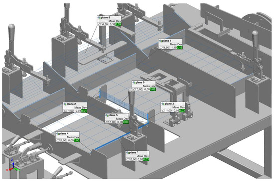
Figure 10.
Illustration of the verification process of the fixture’s flatness.
By utilizing scanning or CAD models, it was possible to obtain complete surface representations of the object and subsequently compare them with reference values. The PolyWorks software allowed the definition of entire surfaces and their accuracy analysis in comparison with reference CAD models or ideal surfaces. If specific inspection of a certain surface area was needed, as shown in Figure 11, it was possible to select and define only that section, allowing for more detailed analysis in areas where a higher risk of errors or issues was anticipated. Additionally, it was possible to select the weldment display for better illustration and apply the elements of the fixture that are movable or adjustable during the process.
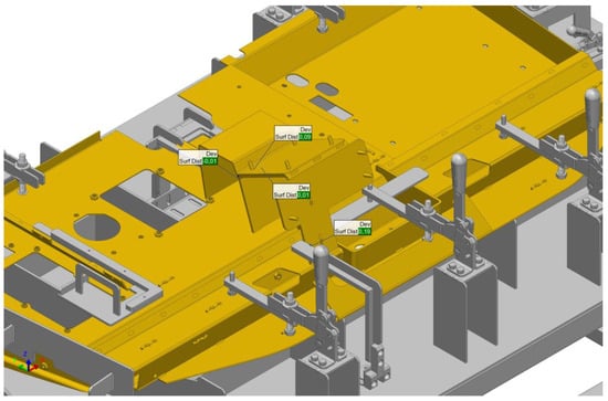
Figure 11.
Verification of the geometric parameters of the welding fixture, including the weldment display and application to selected parts.
In Figure 12, a sample of 13 points was selected within the tolerance range of ±0.7 mm for better representativeness of the results. After evaluating these points, it was determined that all measured values fell within the required tolerances, with no significant deviations detected that could negatively affect the effectiveness of the fixture or the quality of the final product. This result confirms that the designed fixture is fully functional, meets all specified technical parameters, and was manufactured with high precision. These findings also confirm that the fixture is ready for implementation in serial production without the risk of quality issues.
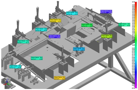
Figure 12.
Illustration of a selected representative sample from the total surface area of the fixture.
Reverse engineering played a crucial role in the verification of the fixture by enabling precise analysis of the physically manufactured fixture and its comparison with the original CAD model. The geometric data obtained through this process allowed for a detailed assessment of deviations between the actual and expected state.
4. Discussion
When verifying the suitability of the welding fixture and its subsequent application in serial production, verification plays a key role. Traditional measurement methods, such as dimension measurement using micrometers or other measuring instruments, may be insufficient for accurately assessing all geometric deviations that can affect part positioning and welding accuracy. In this process, it is essential to consider not only basic dimensional tolerances but also more complex factors, such as proper component positioning, their mutual alignment, and potential deformations during welding. Reverse engineering combined with 3D scanning enabled a detailed analysis of the fixture and an evaluation of all these factors.
The results obtained from PolyWorks Inspector confirmed that deviations from the CAD model were within acceptable tolerances, which would have been difficult to assess using conventional measuring tools.
Table 3, referencing Figure 10, displays the results of flatness measurements of the fixture in individual planes. For each plane, the measured values, required tolerances, and actual deviations are provided. Based on these data, all measurements are within the specified tolerances (marked as “Pass”), confirming that the fixture meets the requirements for flatness and geometric accuracy.
Table 3.
Flatness measurement results.
Table 4 presents the results of surface distance measurements during the verification of the welding fixture. Each surface was measured to assess flatness and deviation from the nominal value in comparison with the tolerance range of ±1.000 mm. All measured surfaces, including Surf 1, Surf 5, Surf 9, and others, showed deviations within the permissible tolerances, indicated by the “Pass” status, confirming that the surface distances of the fixture met the requirements for implementation into production.
Table 4.
Surface distance measurement results.
Without these advanced methods, it would be extremely challenging to determine whether the fixture is truly suitable for serial production and whether it ensures the required quality of welded components. Given the accuracy and functionality demands of the manufacturing process, verification using reverse engineering is essential for ensuring the required quality and eliminating the risk of errors that could affect the entire production process.
Based on the verification and testing of the welding fixture, although the results meet the required tolerances, there are several areas where the process could be further improved and optimized. The first step is to enhance the accuracy of component positioning. Automation of positioning systems, for example, through robotic arms or automatic clamping mechanisms, could improve the speed and precision of part placement, thereby reducing the risk of human errors.
Another possible improvement is to enhance the mechanical and thermal properties of the fixture. The use of materials with better thermal properties or greater resistance to deformation could help prevent thermal stresses during welding, increasing the fixture’s precision and lifespan. However, this approach would involve higher financial costs.
Advanced simulation tools could predict the behavior of materials during welding, allowing for the optimization of component positioning and clamping even before physical production begins. This would reduce the need for physical testing and increase efficiency. Implementing online monitoring systems during welding would enable real-time parameter adjustments, ensuring that the welding process remains within optimal conditions, thereby minimizing potential errors.
5. Conclusions
Reverse engineering has proven to be a highly effective tool in optimizing manufacturing processes, especially in reducing geometric deviations and improving the quality of final products. The use of 3D scanning to collect detailed geometric data allowed for the identification of inconsistencies in design and manufacturing during the early stages of production. This approach enabled the timely implementation of necessary adjustments, leading to significant improvements in the precision of manufacturing processes.
Unlike traditional measurement methods, which can be time-consuming and prone to human error, reverse engineering offers a faster, more accurate, and automated alternative. Three-dimensional scanning allows for the acquisition of complex geometric data, which can be immediately analyzed using specialized software, eliminating the need for manual measurements and reducing the risk of errors. As a result, not only is accuracy improved, but the overall manufacturing process becomes more efficient, minimizing the need for rework and reducing the costs of rework and claims.
The research focused on developing a methodology for verifying geometric components through 3D scanning and deviation analysis, contributing to improved geometric accuracy and product quality. The proposed methodology, implemented in real-world manufacturing processes, allowed for the early detection of inconsistencies and errors, achieving higher compliance with quality requirements and minimizing the need for rework, thus reducing repair costs. The aim was to enhance the reliability and quality of products during the early stages of production, which had a positive impact on the overall efficiency of the manufacturing process. Tests showed that the implementation of this methodology led to a measurable reduction in geometric and welding errors, as well as an increase in the quality of the final products, particularly in the case of welding fixtures and other critical components. The proposed methodology combined theoretical approaches with practical experiments, emphasizing the iterative process of fixture efficiency.
Measurement results indicate that we were able to approach zero deviation. With a tolerance of ±1 mm, the lowest deviation was almost zero, specifically 0.002 mm, which demonstrates the effectiveness of the applied methodology. With the highest tolerance of ±4.5 mm, the maximum deviation was 1.19 mm, and with a tolerance of ±1 mm, we also recorded a deviation of −0.66 mm. This progress is the result of a precise process of verifying geometric components through 3D scanning and deviation analysis.
However, it is important to note that although we aim to ensure consistent conditions during repeated measurements, these processes may be influenced to some extent by various factors, such as small variations in material properties, environmental conditions, or technical settings during individual measurements. These factors may slightly affect the results, although the methodology overall showed significant improvement in accuracy and quality. Despite these potential influences, we still achieve values that are below the requirements set for production, significantly reducing the need for rework and repair costs.
The results suggest that further improvements in the design of welding fixtures are needed to achieve even better performance. Future efforts should focus on more precise adaptation of fixtures to different material properties and changes that occur during the manufacturing process. However, these materials may be more expensive and require additional modifications in production. Such a step could be advantageous in applications where the highest precision is required, but economic considerations and manufacturing capabilities will need to be considered.
A crucial step in process optimization is improving measurement technologies and integrating them with IoT elements directly into welding fixtures. Integrating intelligent sensors and measuring devices that allow real-time parameter adjustments could significantly improve the stability and quality of the manufacturing process. These technologies would enable continuous monitoring of key parameters such as temperature fluctuations, material stress, and deviations from the desired geometry, thus minimizing the likelihood of errors and increasing the overall reliability of the process.
In conclusion, it is also important to note that the method brought measurable improvements in the geometric accuracy of products, with deviations well below the set tolerances, confirming the effectiveness of this methodology in real-world conditions. The implementation of the methodology contributed to higher compliance with quality requirements, which is particularly important in the production of critical components such as welding fixtures. Monitoring and analyzing geometric deviations using 3D scanning allowed for high accuracy in the early stages of production, eliminating the need for further interventions and reducing repair costs.
Although the results showed a positive impact on the quality and reliability of products, further research is recommended, focusing on the broader use of advanced analytical methods and simulations, as well as testing the methodology with different materials and manufacturing conditions. This approach could bring even better results in optimizing welding processes and further reducing geometric deviations.
The results of applying the methodology to other parts of the cabin confirmed its effectiveness in other areas of production, opening the possibility for its broader application in various industrial sectors and processes. This provided a valuable foundation for future research and the implementation of technology that could significantly improve the quality and efficiency of production in various fields.
Author Contributions
Conceptualization, P.G. and J.K.; methodology, P.G.; software, P.G.; validation, P.G., J.K. and M.K.; formal analysis, J.K.; investigation, M.P.; resources, P.G.; data curation, J.K.; writing—original draft preparation, P.G.; writing—review and editing, J.K.; visualization, P.G.; supervision, J.K.; project administration, M.K.; funding acquisition, M.K. and M.P All authors have read and agreed to the published version of the manuscript.
Funding
This research was funded by project KEGA 002TUKE-4/2023 and VEGA 1/0121/23, granted by the Ministry of Education, Research, Development and Youth of the Slovak Republic, and by the EU NextGenerationEU through the Recovery and Resilience Plan for Slovakia under the project No. 09I03-03-V05-00015, and No. 09I05-03-V02-00042.
Institutional Review Board Statement
Not applicable.
Informed Consent Statement
Not applicable.
Data Availability Statement
The original contributions presented in this study are included in the article; further inquiries can be directed to the corresponding author.
Conflicts of Interest
The authors declare no conflicts of interest.
Abbreviation
The following abbreviations are used in this manuscript:
| CMM | Coordinate Measuring Machine |
| ICP | Iterative Closest Point |
| NURBS | Non-Uniform Rational B-Splines |
| RSW | Resistance Spot Welding |
| BSP | Base Sheet Panel |
| FEA | Finite Element Analysis |
| HAZ | Heat Affected Zone |
References
- Mizera, O.; Čepová, L.; Sadílek, M.; Čep, R.; Hrubý, R.; Zelinka, J. The Problems of Measuring Selected Geometric Deviations on a CMM After Machining. In Advances in Manufacturing II: Volume 5-Metrology and Measurement Systems; Springer International Publishing: Cham, Switzerland, 2019; pp. 158–171. [Google Scholar] [CrossRef]
- Pan, F.; Nie, L.; Bai, Y.; Wang, X.; Wu, X. Geometric errors measurement for coordinate measuring machines. In IOP Conference Series: Earth and Environmental Science; IOP Publishing: Bristol, UK, 2017; Volume 81, p. 012117. [Google Scholar] [CrossRef]
- Page, D.; Koschan, A.; Abidi, M. Methodologies and techniques for reverse engineering—The potential for automation with 3-d laser scanners. In Reverse Engineering: An Industrial Perspective; Springer: London, UK, 2008; pp. 11–32. [Google Scholar] [CrossRef]
- Swornowski, P.J. A critical look at the coordinate measuring technique. Mechatronics 2013, 23, 80–93. [Google Scholar] [CrossRef]
- Li, L.; Li, C.; Tang, Y.; Du, Y. An integrated approach of reverse engineering aided remanufacturing process for worn components. Robot. Comput.-Integr. Manuf. 2017, 48, 39–50. [Google Scholar] [CrossRef]
- Helle, R.H.; Lemu, H.G. A case study on use of 3D scanning for reverse engineering and quality control. Mater. Today Proc. 2021, 45, 5255–5262. [Google Scholar] [CrossRef]
- Liu, X.; Wei, Y.; Wu, H.; Zhang, T. Factor analysis of deformation in resistance spot welding of complex steel sheets based on reverse engineering technology and direct finite element analysis. J. Manuf. Process. 2020, 57, 72–90. [Google Scholar] [CrossRef]
- Ruediger, P.; Claus, F.; Hamann, B.; Hagen, H.; Leitte, H. Combining visual analytics and machine learning for reverse engineering in assembly quality control. Electron. Imaging 2020, 33, jist0956. [Google Scholar] [CrossRef]
- Saiga, K.; Ullah, A.S.; Kubo, A. A sustainable reverse engineering process. Procedia CIRP 2021, 98, 517–522. [Google Scholar] [CrossRef]
- Guo, Z.; Liu, X.; Rao, X.; Yuan, C. Effect of defects on the structural integrity of ship piping welds under simulated piping conditions. Ocean. Eng. 2024, 308, 118372. [Google Scholar] [CrossRef]
- Serrati, D.S.; Machado, M.A.; Oliveira, J.P.; Santos, T.G. Non-destructive testing inspection for metal components produced using wire and arc additive manufacturing. Metals 2023, 13, 648. [Google Scholar] [CrossRef]
- Shravan, C.; Radhika, N.N.; Deepak Kumar, N.H.; Sivasailam, B. A review on welding techniques: Properties, characterisations and engineering applications. Adv. Mater. Process. Technol. 2023, 10, 1126–1181. [Google Scholar] [CrossRef]
- Naksri, C.; Chuchom, S.; Chaiprapat, S. Design of Fixture for Welding. In IOP Conference Series: Materials Science and Engineering; IOP Publishing: Bristol, UK, 2021; Volume 1163, p. 012007. [Google Scholar] [CrossRef]
- Arnaoutis, V.; Rosić, B.V.; Lutters, E. Parametric design evolution for production setups; a case study for welding fixtures. Procedia CIRP 2023, 120, 1522–1527. [Google Scholar] [CrossRef]
- Javaid, M.; Haleem, A.; Kumar, L. Dimensional errors during scanning of product using 3D scanner. In Advances in Engineering Design: Select Proceedings of FLAME, Uttar Pradesh, Noida, India 3 October 2018; Springer: Singapore, 2019; pp. 727–736. [Google Scholar] [CrossRef]
- Haleem, A.; Javaid, M.; Singh, R.P.; Rab, S.; Suman, R.; Kumar, L.; Khan, I.H. Exploring the potential of 3D scanning in Industry 4.0: An overview. Int. J. Cogn. Comput. Eng. 2022, 3, 161–171. [Google Scholar] [CrossRef]
- ACE Measuring Arm Range Precisely for You, n.d. Available online: https://www.kreon3d.com/products/ace-measuring-arm (accessed on 7 February 2025).
- Jędrych, M.; Gorzkiewicz, D.; Deja, M.; Chodnicki, M. Application of 3D scanning and computer simulation techniques to assess the shape accuracy of welded components. Int. J. Adv. Manuf. Technol. 2024, 1–9. [Google Scholar] [CrossRef]
- Hegedűs-Kuti, J.; Szőlősi, J.; Varga, D.; Abonyi, J.; Andó, M.; Ruppert, T. 3d scanner-based identification of welding defects—Clustering the results of point cloud alignment. Sensors 2023, 23, 2503. [Google Scholar] [CrossRef] [PubMed]
- Meng, W.; Li, Z.; Huang, J.; Wu, Y.; Chen, J.; Katayama, S. The influence of various factors on the geometric profile of laser lap welded T-joints. Int. J. Adv. Manuf. Technol. 2014, 74, 1625–1636. [Google Scholar] [CrossRef]
- Liu, S.; Wu, Z.; Liu, H.; Zhou, H.; Deng, K.; Wang, C.; Liu, L.; Li, E. Optimization of welding parameters on welding distortion and stress in S690 high-strength steel thin-plate structures. J. Mater. Res. Technol. 2023, 25, 382–397. [Google Scholar] [CrossRef]
- Neuvonen, R.; Peltoniemi, T.; Skriko, T.; Ghafouri, M.; Amraei, M.; Ahola, A.; Björk, T. The effects of geometric and metallurgical constraints on ultra-high strength steel weldments. Structures 2023, 56, 104900. [Google Scholar] [CrossRef]
- Singh, I.J.; Murtaza, Q. A comprehensive review on effect of cold metal transfer welding parameters on dissimilar and similar metal welding. J. Eng. Res. 2023. [Google Scholar] [CrossRef]
- Ikumapayi, O.M.; Akinlabi, E.T.; Madushele, N.; Fatoba, S.O. A brief overview of bending operation in sheet metal forming. In Advances in Manufacturing Engineering: Selected Articles from ICMMPE 2020; Springer: Berlin/Heidelberg, Germany, 2019; pp. 149–159. [Google Scholar] [CrossRef]
- Seloane, W.T.; Mpofu, K.; Ramatsetse, B.I.; Modungwa, D.J.P.C. Conceptual design of intelligent reconfigurable welding fixture for rail car manufacturing industry. Procedia CIRP 2020, 91, 583–593. [Google Scholar] [CrossRef]
- Kadam, G.; Nagarajan, B.; Mirji, V.; Sawant, S. Design of Rigid-Locking Variable-Angular-Span Welding Fixture. Eng. Proc. 2024, 66, 35. [Google Scholar] [CrossRef]
- Kang, S.; Yun, W.; Kim, H.; Kim, J.; Ji, C.; Lee, K.; Kim, J.; Jang, H.-L.; Chun, K. A Study on Minimizing Welding Deformation of Joints for the Sealing of Emission After-Treatment Structure. Materials 2021, 14, 6982. [Google Scholar] [CrossRef]
- Liu, S.; Wu, Z.; Zhou, W.; Zhou, H.; Zhang, K.; Yin, D.; Lei, Y.; Qiu, Y. A review of welding simulation methods for large components. Prog. Nat. Sci. Mater. Int. 2023, 33, 551–568. [Google Scholar] [CrossRef]
- Jha, N.K. Design and analysis of welding fixture for elementary weld joints. CVR J. Sci. Technol. 2018, 15, 90–95. [Google Scholar] [CrossRef]
- Viňáš, J.; Brezinová, J.; Guzanová, A.; Svetlík, J. Degradation of renovation layers deposited on continuous steel casting rollers by submerged arc welding. Proc. Inst. Mech. Eng. Part B J. Eng. Manuf. 2013, 227, 1841–1848. [Google Scholar] [CrossRef]
Disclaimer/Publisher’s Note: The statements, opinions and data contained in all publications are solely those of the individual author(s) and contributor(s) and not of MDPI and/or the editor(s). MDPI and/or the editor(s) disclaim responsibility for any injury to people or property resulting from any ideas, methods, instructions or products referred to in the content. |
© 2025 by the authors. Licensee MDPI, Basel, Switzerland. This article is an open access article distributed under the terms and conditions of the Creative Commons Attribution (CC BY) license (https://creativecommons.org/licenses/by/4.0/).