Article

Study on the Design of the Gear Pair and Flow Characteristics of Circular-Arc Gear Pumps

1
School of Mechatronics Engineering, Henan University of Science and Technology, Luoyang 471003, China
2
State Key Laboratory of Shield Machine and Boring Technology, Zhengzhou 450001, China
*
Author to whom correspondence should be addressed.
Appl. Sci. 2025, 15(7), 3911; https://doi.org/10.3390/app15073911
Submission received: 10 February 2025 / Revised: 14 March 2025 / Accepted: 1 April 2025 / Published: 2 April 2025
(This article belongs to the Section Mechanical Engineering)

Abstract

:
Compared with traditional gear pumps, circular-arc gear pumps have the advantages of silence and small flow pulsation, but the theory of design is underdeveloped. This paper presents a design method for gear pumps with circular-arc helical gear pairs, and the influence mechanism of flow characteristics is studied. First, a model of the gear pair is established, and a design method for the gear pair is proposed. Second, a CFD model is demonstrated, and the influences of the tooth profile parameters (tooth number, modules, and pressure angle) on the flow characteristics are analyzed. Finally, the significance of the influencing factors is analyzed. The results show that when the stagger angle of the two ends of the arc helical gear pair is an integral multiple of π/Z, there is no flow pulsation, and there is little noise. The tooth number and modules are positively correlated with the flow rate and flow pulsation, among which the modules have the most significant influence. The flow rate of the gear pump increases by 4–5 L/min for every 0.2 increase in the modules. The pressure angle and flow rate show a negative correlation trend, but the influence is insignificant. The flow rate is less than 1 L/min for every 2° change in the pressure angle. This paper provides a theoretical basis and reference value for the gear pair design of gear pumps.

1. Introduction

With the continuous iteration of technology, the hydraulic system has higher requirements for hydraulic pumps. First, with the development of the aerospace field, there is a high demand for a high power-to-weight ratio [1]. As the flow rate depends on the displacement and rotation speed, under the premise of fixed displacement, the higher the rotation speed is, the greater the flow rate. Therefore, the method of reducing the displacement and increasing the rotation speed can improve the power-to-weight ratio. Second, because of the development of the electrical era, hydraulic pumps should also be able to work at high speed to adapt to high-speed motors [2]. Therefore, high-speed, high-pressure, miniaturized hydraulic pumps have become a development trend. Thus, gear pumps are more suited for higher speeds, often as main and fuel pumps for aircraft engines [3]. However, traditional gear pumps have some inevitable problems due to their structural characteristics, such as oil trapping, cavitation, and flow pulsation. These problems restrict the high-speed development of gear pumps. Nagamura, K. attempted to study multiple tooth profiles and produced an involute–cycloid composite tooth profile. The gear pump has a relatively large displacement but is still prone to oil trapping [4]. Circular-arc gear pumps are structurally designed to eliminate oil trapping and thus minimize flow pulsations [5]. Huang K studied a microsegment tooth profile, which is oil-free and has a relatively high maximum working pressure, and the tooth profile is a circular gear [6]. Therefore, this gear pump has good development prospects. However, it possesses stringent design requirements for its gear pairs, and suboptimal design will still have adverse effects, such as flow pulsation. Hence, studying the mechanism of flow characteristics and designing gear pairs based on this theory are highly important.
Many studies have been conducted on circular-arc gear pumps at home and abroad. Rexroth showcased a silent pump at the 2011 Hannover exhibition in Germany, which has low noise and low flow pulsation. The gear pump features a double-arc tooth profile [7]. Thomas Ranregnola developed an algorithm for comparing the performance of spur and helical gear pairs, revealing that the helical gear pump produced less noise [8]. Williams, L. T. designed a circular helical gear that has higher volumetric efficiency and lower noise than spur gears of the same size [9]. Xu Hongwei revealed the fundamental flow characteristics through theoretical analysis and utilized an algorithm to mitigate flow pulsations [10]. Liang Yankun addressed the equation of a rack gear pair and then estimated the approximate displacement of the pump via a specific formula [11]. Zhou Yang focused on a gear pair with an involute transition curve to investigate how tooth profile parameters affect performance [12]. Zhao et al. [13] proposed a numerical method to calculate the sine curve, and the results show that the circular gear pump with a spur gear still has large flow pulsation. Wei Xiaoxiao studied the vibration and dynamics of a circular-arc helical gear pump through simulation [14]. Wu Yifei derived the axial force formula for the circular-arc helical gear pump and used it to analyze its impact on leakage [15]. Gregov used a hydraulic motor as the object and established a prediction model using neural networks, which can be used as a reference for modeling and prediction for other aspects [16]. Rundo discussed various simulation methods for the simulation analysis of gear pumps [17]. Antoniak has developed a visualization method that provides new ideas for the study and analysis of the flow field in gear pumps [18]. Most of the research objects mentioned above are circular-arc gear pumps with involute curves as transition curves, but some studies have shown that gear pumps with sinusoidal curves as transition curves have better performance. Pan Jiulin comprehensively analyzed the characteristics of gear pumps with various tooth profiles, such as straight lines, involutes, cycloids, and circular-arc curves, from a theoretical perspective. The results show that the composite curve formed by the combination of arc and sine curves has the characteristics of a low sliding rate and small pulsation [19]. In summary, the sliding rate of gear pairs using sine curves as transition curves is lower, and the flow rate is more stable; therefore, the gear pair has less wear and low noise. However, currently, most gear pairs of circular-arc gear pumps use an involute as the transition curve, and there is little research on gear pairs with sinusoidal curves. The influence mechanism between gear pair design parameters and flow characteristics has not been well studied.
This study aims to enhance the design of the gear pairs of a circular-arc gear pump by taking the gear pair featuring a sine transition curve as the object of study. Through a comprehensive theoretical analysis of the tooth profile design and flow characteristics, parameters that have an impact on the flow characteristics were obtained. Then, the influence mechanism between the gear pair design parameters and flow characteristics was analyzed through simulation, and correlation analysis was conducted to obtain the parameters with significant impacts. This study enriches the theory of gear pairs for circular-arc gear pumps and provides valuable insights for designing such gear pairs.

2. Material and Methods

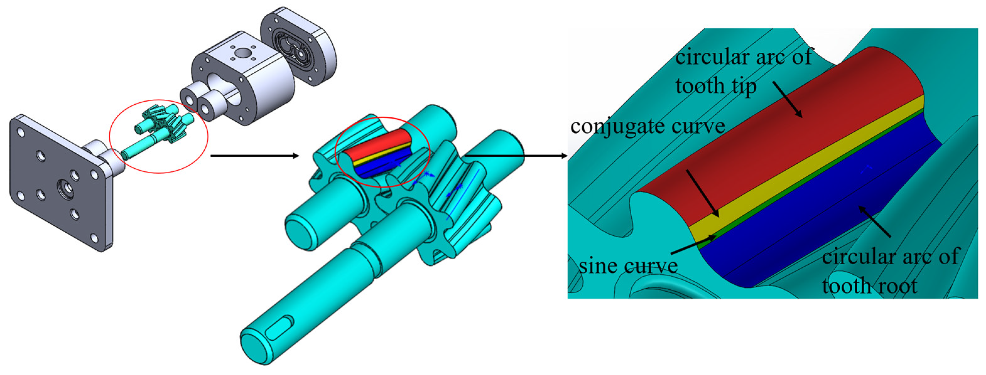
2.1. Structure of a Circular-Arc Helical Gear Pump

Figure 1 shows the structure of a circular-arc helical gear pump. This gear pump has a three-piece structure, which achieves oil suction and discharge by the sealed volume change generated by rotating the gear pair. The tooth profile of the gear pair is composed of the circular arc of the tooth root, the circular arc of the tooth tip, and a transition curve connecting the tooth root and tooth tip. The transition curve of the gear pair used in this study is composed of two segments of curves spliced together. One segment is a sine curve, and the other segment is a conjugate curve of the sine curve. As shown in Figure 1, blue represents the tooth root arc, red represents the tooth tip arc, green represents the sine curve, and yellow represents the conjugate curve of the sine curve.

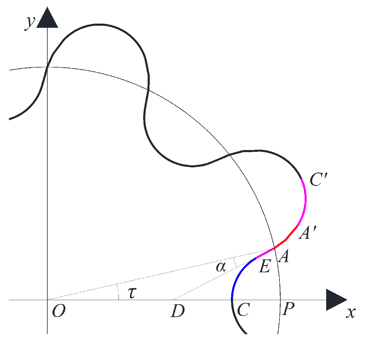
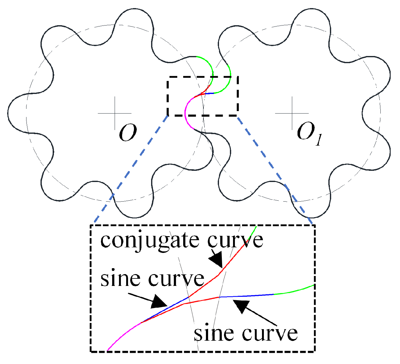
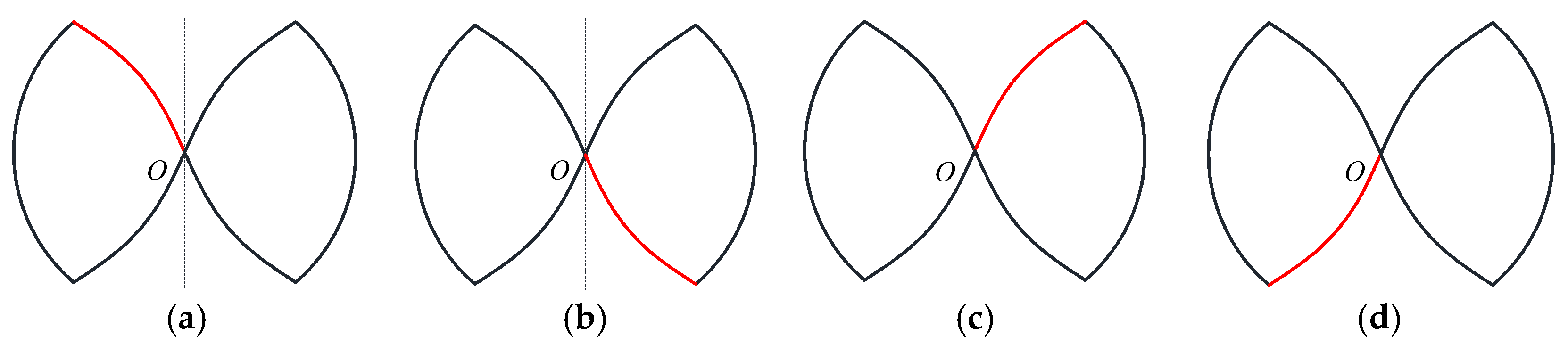
2.2. Mathematical Model of the Tooth Profile

Establishing a mathematical model for the tooth profile is necessary to design and theoretically analyze the gear pair, thereby obtaining the design parameters. Figure 2 shows a schematic diagram of a partial tooth profile. When the gear pair is working, the meshing process of each pair of teeth is the same, and the shape of a single tooth is symmetrical, so only the mathematical model of half of the teeth needs to be solved. The curve CC’ is the one-half tooth curve to be solved. It comprises a circular arc of tooth root CE, sine curve AE, conjugate curve AA’ and a circular arc of tooth tip AC’. The specific solution process is as follows:

2.2.1. The Equation of the Sine Curve

Let the parametric equation for the sine curve AE be as follows:
x = t R y = a R sin N ( t t 0 )
where R denotes the radius of the pitch circle; N, a and t0 are unknowns; and t is the parameter of the parametric equation. Make a tangent AD at point A on the pitch circle and intersect the X-axis at point D. Then, α is equal to the pressure angle, τ is the angle corresponding to two teeth and τ = π/2Z.
Through mathematical deduction, the following conclusions can be drawn [20]:
t A = cos π 2 Z a = sin π 2 Z sin N ( t A t 0 ) N = π 2 ( 1.5 t 0 ) N sin π 2 Z = tan ( π 2 Z + α ) tan N ( t A t 0 )
From the above equations, the unknown variables can be solved to solve the parameter equation.

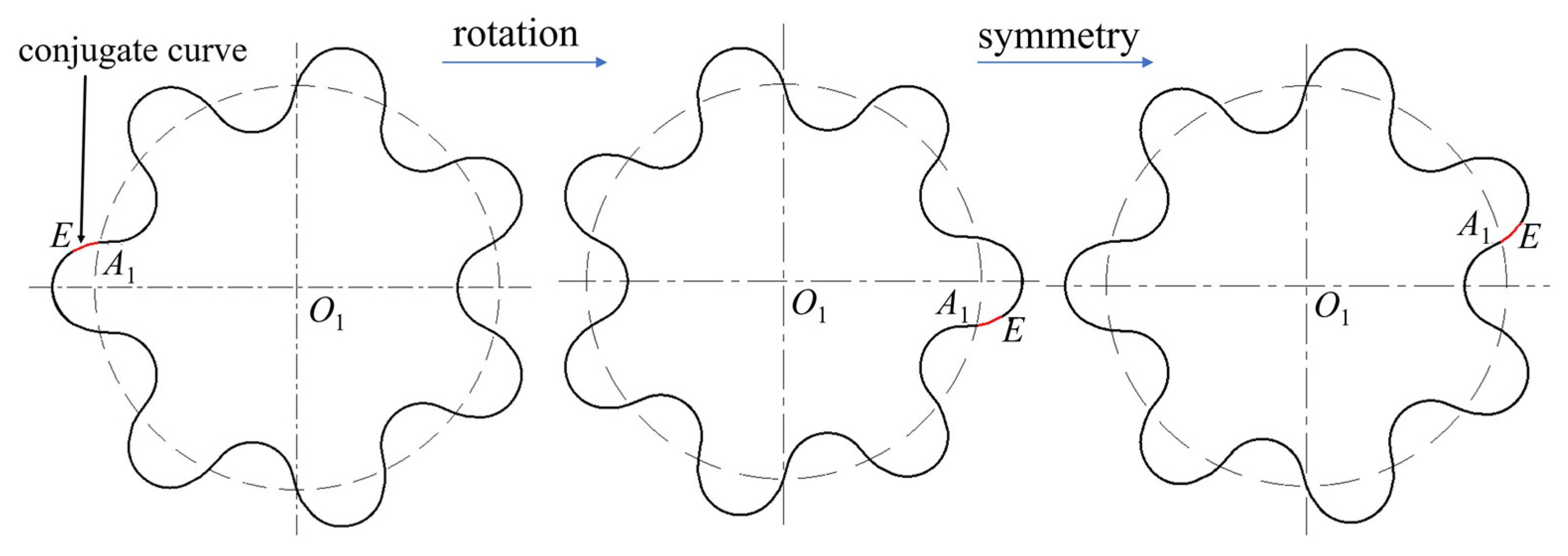
2.2.2. The Equation of the Conjugate Curve

Figure 3 shows a schematic diagram of the gear pair engaging on a transition curve. Based on the meshing principle, the sine curve on the left gear (hereinafter called gear O) has a conjugate curve on the right gear (hereinafter called gear O1), so there is also a curve on gear O that is conjugated with the sine curve on gear O1. This curve is the conjugate curve AA’ that we must solve. The equation of this conjugate curve can be obtained via the conjugate curve equation on another gear through matrix transformation. The transformation process is shown in Figure 4. The position of the conjugate curve EA1 on gear O1 after rotation and symmetry is the position of the conjugate curve AA’ on gear O.
At this point, the equation of the transformed curve EA1 is the equation of the desired conjugate curve. The equation for EA1 obtained from the tooth profile normal method is as follows [21]:
x 1 = x cos 2 φ 2 R cos φ y sin 2 φ y 1 = x sin 2 φ 2 R sin φ + y cos 2 φ
where φ satisfies the following equation:
tan γ = d x d y cos ψ = y cos γ + x sin γ R φ = π 2 ( γ + ψ )
Further coordinate transformation of Equation (3) yields the equation for A A as follows:
x 2 = t R cos ( 2 φ + π Z ) + 2 R cos ( φ + π Z ) + a R sin N ( t t 0 ) sin ( 2 φ + π Z ) y 2 = t R sin ( 2 φ + π Z ) + 2 R sin ( φ + π Z ) a R sin N ( t t 0 ) cos ( 2 φ + π Z ) ( t E t t A )

2.2.3. Equation of the Tooth Root and Tooth Tip

The tooth root CE is a circular arc with PE as the radius and P as the center, so the radius can be calculated as follows:
r = P E ¯ = ( R x E ) 2 + y E 2
Let the tooth height coefficient f 1 be as follows:
f 1 = Z a 2 sin 2 N ( t E t 0 ) + ( 1 t E ) 2 2
where Z is the number of teeth. At point E, there is the following:
θ E = arcsin ( y E r ) = arcsin ( a Z sin N ( t E t 0 ) 2 f 1 )
Therefore, the equation for the tooth root is as follows:
x 3 = R r cos θ y 3 = r sin θ ( 0 < θ < θ E )
where θ is the parameter of the parameter equation, similarly, the equation for the tooth tip AC’ is as follows:
x 4 = R cos π Z + r cos ( π Z θ ) y 4 = R sin π Z + r sin ( π Z θ ) ( 0 < θ < θ E )
Thus far, a mathematical model has been established. According to the solving process, the parameters affecting the tooth profile are as follows: tooth number Z, modules m, and pressure angle α. Therefore, the design parameters of the circular-arc gear pump consist of these three parameters.

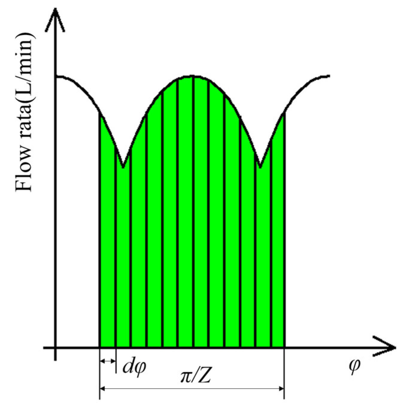
2.3. Analysis of the Flow Characteristics Mechanism

To achieve no flow pulsation, the circular-arc gear pump has stringent design requirements for its gear pairs. Therefore, to design gear pairs reasonably, it is necessary to study and analyze the flow characteristic mechanism. According to the volume change method, the volume change caused by the gear pair is the flow rate [22]. From this, the flow rate q s h c can be calculated as follows:
q s h z = b ω ( r a 2 r w 2 f 2 )
where b is the tooth width; ra is the radius of the tooth tip; rw is the radius of the pitch circle; ω is the speed of the gear pump; and f represents the distance from the point of meshing to the node:
f = ( x r w ) 2 + y 2
The above equation indicates that the flow rate is related to the meshing curve of the gear pair. After calculation, the meshing curve can be obtained, as shown in Figure 5.
The figure shows that the meshing curve is symmetrical. Only by solving for the flow corresponding to one section of the meshing curve can the flow curve of the entire cycle be obtained. The final trend of the flow curve is illustrated in Figure 6. The figure shows that the circular-arc spur gear pump exhibits flow pulsation with a period of π/2Z. Therefore, helical teeth are required to reduce pulsation.
The helical gear pair can be seen as countless thin microelement thin sheets and end faces that are staggered at a certain angle in sequence. The angle φ offset from the end face with the distance h of the thin sheet in the axial direction follows the following equation:
φ = h × tan β R
where β is the spiral angle on the cylindrical surface of the pitch circle. Therefore, the flow rate of the helical gear pump can be calculated by integrating the flow rates of countless microelement thin sections:
q s h = b 2 b 2 ω ( r a 2 r w 2 f 2 ) d h
The above equation can be represented by the green area in Figure 6. If the integration interval is set as one cycle, π/2Z, the integration area can be kept constant; that is, the flow rate remains unchanged, thus causing the circular-arc helical gear pump to have “no flow pulsation”.

2.4. Simulation Analysis

First, to verify the theory in this paper and study the influence of the tooth profile parameters on the flow characteristics, simulation analysis of the flow characteristics of the arc helical gear pump with different tooth numbers, modules, and pressure angles was carried out via Simerics MP+ version 6.0.0.

2.4.1. Simulation Model

First, a three-dimensional model of the gear pair and shell was established. Then, as shown in Figure 7, the fluid region was extracted from the established three-dimensional model. The fluid region was segmented into three parts for grid division, namely, the oil suction port (blue), the gear area (green), and the oil discharge port (red). The inlet was configured as a pressure inlet with a pressure of 0 MPa, whereas the outlet was configured as a pressure outlet with a pressure of 25 MPa. The turbulent flow model was used to simulate a rotational speed of 10,000 r/min.

2.4.2. Simulation Scheme

(1)
Flow pulsation simulation
To verify that the characteristics of a circular-arc helical gear pump are “no flow pulsation”, simulations and comparative analyses were employed in this study using spur and helical gear pumps, both of which were configured with identical parameters. This study is independent of the other parameters of the gear pair, so an existing set of parameters was used for analysis. The parameters are presented in Table 1.
(2)
Simulation analysis of parameter influence
According to the mathematical model of the flow rate, the parameters that impact the flow rate are the number of teeth, modules, and pressure angle. To study how each parameter affects the flow rate, the control variable method was adopted in this study, that is, keeping two parameters unchanged, changing a single tooth profile parameter, and conducting simulation analysis.
As this paper studies the background of high speed, small displacement, and miniaturization, the gear pair design parameters were selected such that the gear pump displacement was less than 5 mL/r and the gear tip diameter was less than 50 mm. The simulation parameters are outlined in Table 2.
Three-dimensional models were established for different parameters in the above table, and the flow curve was obtained through flow field simulation via SIMERICS.

2.5. Pulsatility Evaluation and Spearman Rank Correlation Coefficient

The standard deviation is an important indicator used in statistics to measure the degree of dispersion of the data distribution and describes the degree of deviation between each value in a dataset and the mean. In this work, it was used to evaluate the degree of deviation between the flow rate and the average flow rate to assess the flow pulsation. The formula is as follows:
σ = 1 N i = 1 N ( x i μ ) 2
In the formula, σ is the standard deviation, xi is the element of the dataset, and μ is the mean of the dataset.
To investigate the degree of parameter influence on flow characteristics, a correlation analysis of the effects of the tooth number, modules, and pressure angle on the flow rate and standard deviation was conducted in this study. Correlation analysis was performed via the Spearman rank correlation coefficient. The mathematical model is as follows:
If all n ranks are distinct integers, they can be commonly represented by rs via the following formula [23]:
r s = 1 6 i = 1 n d i 2 n n 2 1
where rs is the Spearman rank correlation coefficient; n is the sample size (number of observations).
The difference di between two ranks (rg) of each observation rg(Xi) and rg(Yi) is defined as follows:
d i = rg ( X i ) rg ( Y i )

3. Results

Through simulation analysis, we verified the above theory and analyzed the simulation results to obtain the flow characteristics of the circular gear pump.

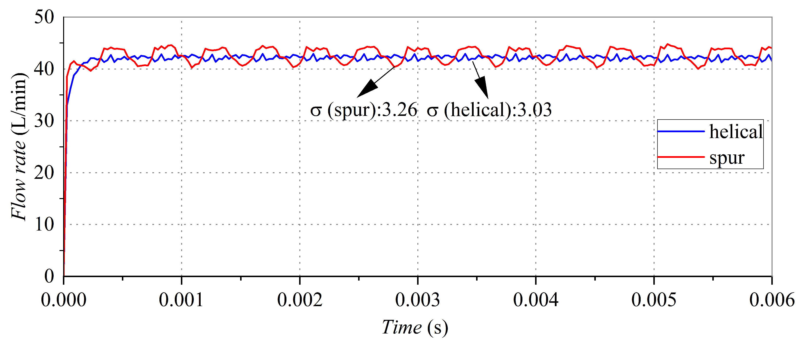
3.1. Flow Pulsation Simulation

Figure 8 shows the flow rates of spur and helical gear pumps with the same tooth profile parameters. The flow rate data indicate that the standard deviation for the flow rate of a spur gear pump is 3.26, and the flow shows a periodic pulse with large pulsation.
The standard deviation of the helical gear pump is 3.03, the flow rate is stable, and the pulse is small, but there is still a periodic peak and trough. Andrea Vacca conducted a study on flow characteristics via a circular-arc helical gear pump, and flow pulsation also occurred during the study [24]. The flow curves in this study are roughly the same, which indirectly verifies the correctness of the simulation in this study. Although the circular-arc helical gear pump theoretically has no flow pulsation, under the influence of manufacturing accuracy and actual factors, the observed center distance of the gear pair exceeds the calculated theoretical value, so there is clearance when the root and top of the gear pair mesh. Thus, peaks and troughs appear in the flow rate at every π/Z corner. From the perspective of flow rate, the average flow rate of the two gears is equal, so the helical gear can be calculated as the spur gear when the displacement is calculated to simplify the calculation.

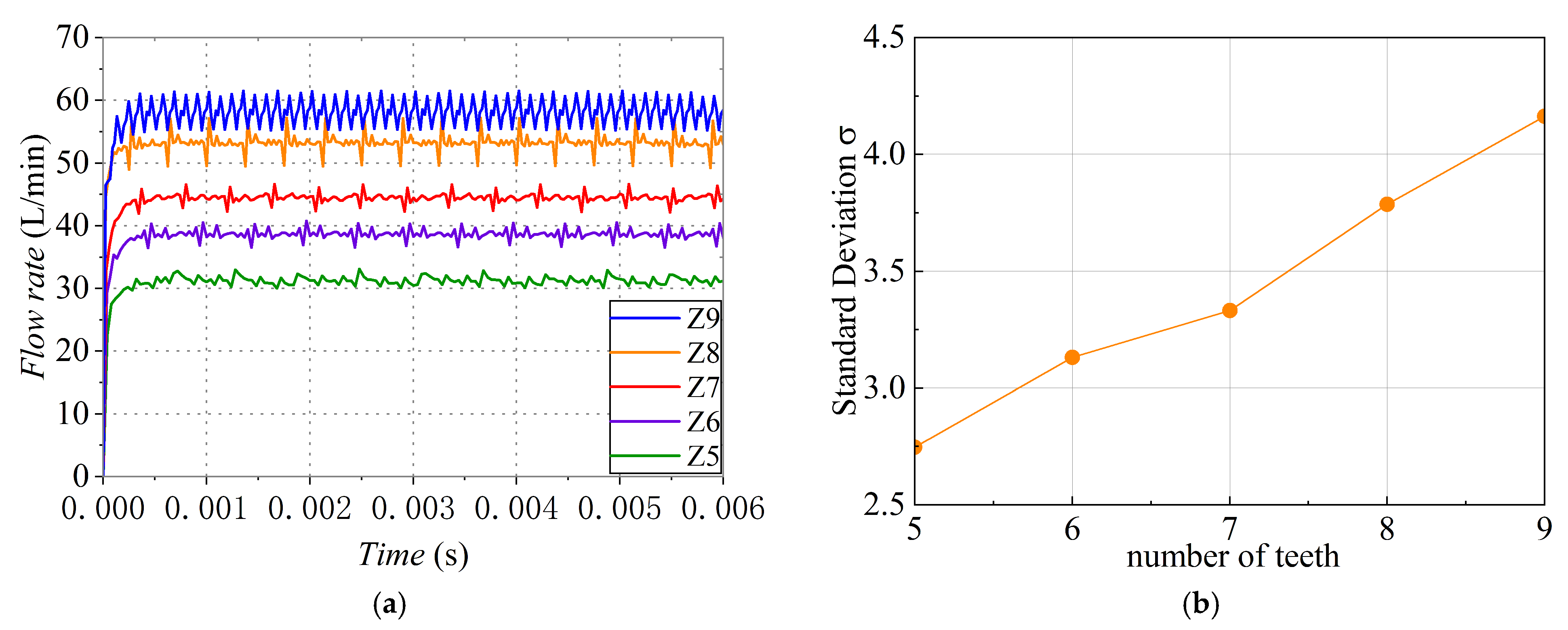
3.2. Effect of the Number of Teeth on the Flow Characteristics

Figure 9 shows the influence of different tooth numbers on flow characteristics. The flow rate of different numbers of teeth in Figure 9a indicates that for every additional tooth number in the gear pair, the flow rate increases by 6–7 L/min. The flow curves with different numbers of teeth have the same trend and exhibit periodic fluctuations. However, the number of fluctuations varies, with flow curves with 5–9 teeth fluctuating 10, 12, 14, 16, and 18 times, respectively. The effect of the number of teeth on the flow rate is the same as that for conventional gear pumps; for example, Manning studied the effect of the number of teeth on conventional gears [25]. An increase in the number of teeth of a circular gear pump also increases the flow rate. This is because with an increasing number of teeth, the volume of the gear pair increases, and the volume change increases, thus increasing the displacement of the gear pump and increasing the flow rate. Based on the analysis in Section 3.1, the gear pair has wave crests and troughs when the tooth top and tooth root mesh are used, so the number of fluctuations should be 2Z, and the simulation results conform to the above analysis, which also indicates that the flow pulsation of the circular gear pump mainly comes from the gap between the gear pairs. As the increase in gear volume also increases the gap between gear pairs, the flow pulsation of the circular gear pump increases. Therefore, reducing the number of teeth can reduce the number of fluctuations, and the standard deviation is reduced so that the flow rate quality is higher and the pulsation is smaller.

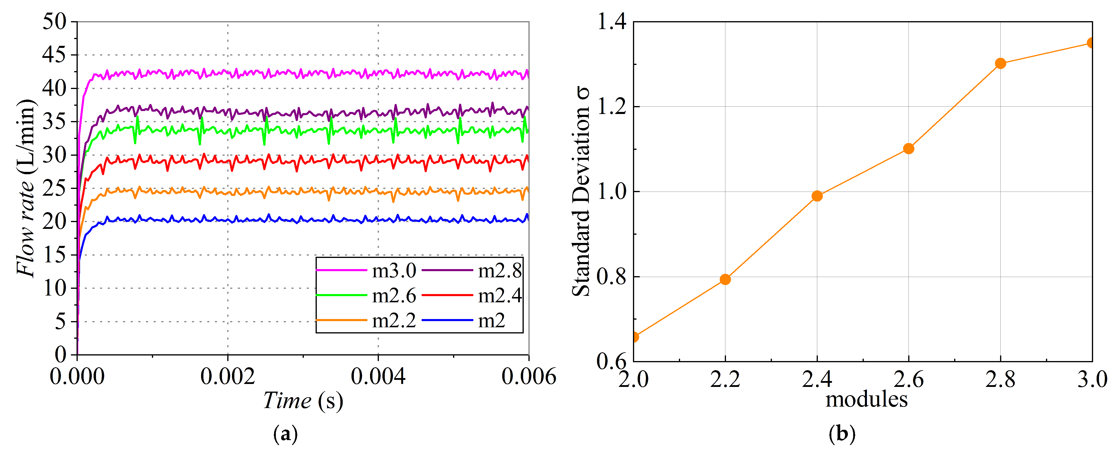
3.3. Effect of the Module on the Flow Characteristics

Figure 10a shows the flow rates for different modules. The figure shows that the average flow rate is 20 L/min when the module is 2. An increase in the module increases the flow rate. When the module increases from 2 to 3 at an interval of 0.2, the gear pump flow rate increases in turn from 4 to 5 L/min. The fluctuations in the flow rate indicate that a change in the module has no influence on the fluctuation frequency. Since the number of teeth is the same, the fluctuation frequency of the flow rate is 14. The reason for the increase in flow rate is similar to the change in the number of teeth. When the module increases, the volume of the gear pair increases, and the volume change increases, so the displacement of the gear pump increases, and the flow rate increases accordingly; at the same time, the increased gap leads to increased flow pulsation of the gear pump.

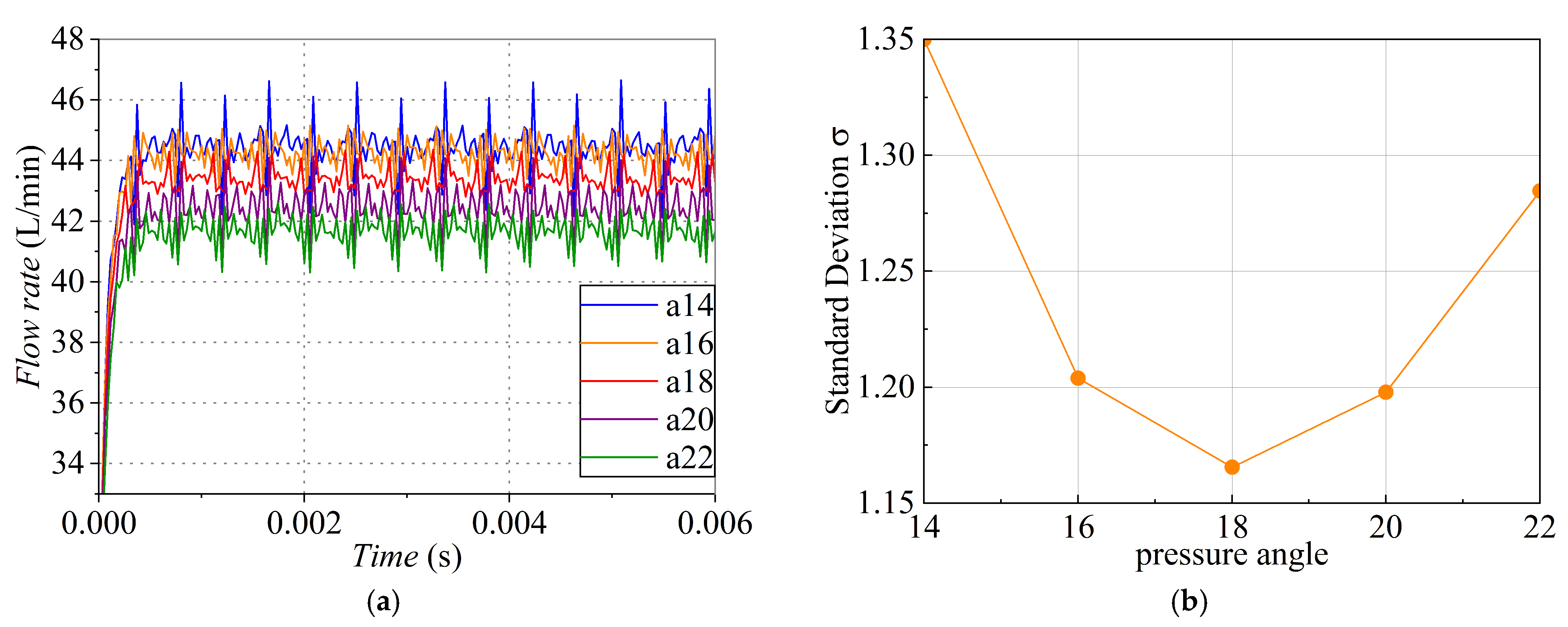
3.4. Effect of Pressure Angle on Flow Characteristics

Figure 11 shows the simulation results of the influence of different pressure angles on the flow characteristics of the gear pump. As shown in Figure 11a, the trend of the flow rate is the same for different pressure angles, and the change in flow rate magnitude is relatively small. As the pressure angle increases, the flow rate decreases, and for every 2° change in the pressure angle, the change in flow rate is less than 1 L/min. The standard deviation initially decreases but then increases as the pressure angle increases. When the pressure angle is set at 18°, the standard deviation is the smallest at 1.16. Unlike the trends of the tooth number and module, the change in the pressure angle does not excessively affect the volume of the gear pair but reduces the volume change to a small extent, so the flow rate change is small. At the same time, the change in the pressure angle has a nonlinear influence on the gap between two gears, so the flow pulsation also has a nonlinear change. Therefore, when gear pairs are designed for flow rate, the influence of the pressure angle is relatively small. When considering flow pulsation, it is not advisable to simply reduce or increase the pressure angle. Choosing an appropriate pressure angle is beneficial for reducing flow pulsation.

3.5. Correlation Analysis

By processing all the above simulation data, the correlation coefficients between them can be obtained, and the correlation coefficients are shown in Table 3.
The correlation coefficient represents the direction and degree of influence. If the value is greater than zero, the two parameters are positively correlated; if it is less than zero, the two parameters are negatively correlated. The closer the absolute value of the value is to 1, the more significant the correlation. A value less than 0.05 indicates a significant correlation, whereas a value less than 0.01 indicates an extremely significant correlation [26]. According to the table, the correlation coefficient between the number of teeth, module, and flow rate is greater than zero, indicating a positive correlation. The correlation coefficient between the pressure angle and flow rate is negative. The significance of the number of teeth is at the 0.05 level, indicating a significant impact on the flow rate. The module is at the 0.01 level, indicating an extremely significant impact on the flow rate. The significance of the pressure angle is greater than 0.05, and its effect on the flow rate is not significant. According to the correlation coefficient between the profile parameters and standard deviation, the module has an extremely significant effect on flow pulsation. The influence decreases in the order of module, pressure angle, and number of teeth.
From the correlation analysis, it can be concluded that the module has the greatest impact on the flow rate, followed by the tooth number, whereas the pressure angle has no significant effect on the flow rate. The impact of the module on the flow pulsation is most significant, whereas the influence of the pressure angle is greater than that of the tooth number. Therefore, when gear pairs with the same flow rate are designed, adopting a small module can reduce the flow pulsation.

4. Conclusions

For the design of circular gear pairs, the theoretical aspects were first analyzed in this study, and the parameters affecting the flow rate characteristics of gear pumps were obtained and verified through fluid simulation. Then, the control variable method was used to analyze the influence of different design parameters on the flow characteristics. The results show the following:
The number of teeth, module, pressure angle, and spiral angle are the design parameters that affect the flow characteristics of the gear pump. The spiral angle ensures that the gear pump is “free of flow pulsation”. For the circular gear pump to be free of flow pulsation, a specific helix angle is required so that the angle at both end faces of the gear is staggered by an integral multiple of π/Z.
In terms of flow rate, the number of teeth and the module have the greatest influence on the displacement of the gear pump. At a rotating speed of 10,000 r/min, the flow rate of the gear pump increases by 6~7 L/min for each additional tooth. For each 0.2 increase in the module, the flow rate of the gear pump increases by 4–5 L/min. However, the pressure angle has little influence on the flow rate. The flow change is less than 1 L/min for every 2° change in the pressure angle. From the perspective of flow pulsation, the module has a great influence on the flow pulsation of the gear pump, and an increase in the module increases the flow pulsation of the gear pump. Next is the pressure angle. The influence of the pressure angle on flow pulsation is nonlinear, showing a trend of first decreasing and then increasing.
The method of controlling variables was used in this work to study the influence of a single tooth profile parameter on flow characteristics, without analyzing the impact of multiple parameters working together. Therefore, the application scenarios of this design method are limited. In the future, the performance of gear pumps under the joint effect of multiple parameters can be studied to better guide the design of such circular-arc helical gear pumps.

Author Contributions

Methodology, G.L.; Writing—original draft, Y.L.; Formal analysis, W.H.; Resources, D.L.; Validation, S.W. and Z.H. All authors have read and agreed to the published version of the manuscript.

Funding

The research is supported by the Henan Provincial Key Research and Development Special Project (251111220200); The research is supported by the Natural Science Foundation of Henan Province Project (252300420446).

Institutional Review Board Statement

Not applicable.

Informed Consent Statement

Not applicable.

Data Availability Statement

The detailed data are available upon request. The data are not publicly available due to privacy.

Conflicts of Interest

The author declares that there are no conflicts of interest. And the author and co-authors have collaborated previously, so there are no conflicts of interest.

References

  1. Chao, Q.; Zhang, J.; Xu, B.; Huang, H.; Pan, M. A review of high-speed electro-hydrostatic actuator pumps in aerospace applications: Challenges and solutions. J. Mech. Des. 2019, 141, 050801. [Google Scholar]
  2. Hao, Y.; Hao, J. Review of the Hydraulic and Structural Design of High-Speed Centrifugal Pumps Front. Energy Res. 2022, 10, 899093. [Google Scholar]
  3. Xu, B.; Liu, Q.; Zhu, Z. Influence of the Rotation Speed on the Internal Flow Characteristics of an Aircraft Fuel Gear Pump. Processes 2024, 12, 576. [Google Scholar] [CrossRef]
  4. Nagamura, K.; Ikejo, K.; Tutulan, F.G. Design and performance of gear pumps with a non-involute tooth profile. Proc. Inst. Mech. Eng. Part B J. Eng. Manuf. 2004, 218, 699–711. [Google Scholar]
  5. Zhou, Y.; Che, B.; Yuan, C. The design and analysis of a high-speed circular arc gear pump journal bearing. Adv. Mech. Eng. 2018, 10, 1687814018819288. [Google Scholar]
  6. Huang, K. Design and fluid analysis of the microsegment gear tooth profile for pump operating at high speed and high pressure. Proc. Inst. Mech. Eng. Part E J. Process Mech. Eng. 2023, 09544089231190181. [Google Scholar] [CrossRef]
  7. Zhang, H. Report about Hannover Messe 2011. Hydraul. Pneum. Seals 2011, 31, 5–9. [Google Scholar]
  8. Ransegnola, T.; Zhao, X.; Vacca, A. A comparison of helical and spur external gear machines for fluid power applications: Design and optimization. Mech. Mach. Theory 2019, 142, 103604. [Google Scholar]
  9. Williams, L.T. Design and Performance of a Curvilinear Circular-Arc Tooth Gear for Gear Pump Applications. In Fluid Power Systems Technology; American Society of Mechanical Engineers: New York, NY, USA, 2020; Volume 83754, p. V001T01A029. [Google Scholar]
  10. Xu, H.; Huang, J. Research on Control Algorithm of Solvent-Free Compound Mixing Ratio Based on Feedforward Control. In China Academic Conference on Printing and Packaging; Springer Nature Singapore: Singapore, 2022; pp. 345–352. [Google Scholar]
  11. Liang, Y. Double Circular Arc Gear Pump Design; Zhengzhou Research Institute of Mechanical Engineering: Zhengzhou, China, 2015. [Google Scholar]
  12. Zhou, Y.; Hao, S.; Hao, M. Design and performance analysis of a circular-arc gear pump operating at high pressure and high speed. Proc. Inst. Mech. Eng. Part C J. Mech. Eng. Sci. 2016, 230, 189–205. [Google Scholar]
  13. Zhao, X.; Vacca, A. Numerical analysis of theoretical flow in external gear machines. Mech. Mach. Theory 2017, 108, 41–56. [Google Scholar]
  14. Wei, X.; Han, Y. Simulation of Flow-Induced Vibration and Dynamic Performance of Circular-Arc Helical Gear Pump under Background of Machine Learning. Int. Trans. Electr. Energy Syst. 2022, 2022, 9513357. [Google Scholar]
  15. Wu, Y.; Ge, P.; Bi, W. Analysis of axial force of double circular arc helical gear hydraulic pump and design of its balancing device. J. Cent. South Univ. 2021, 28, 418–428. [Google Scholar]
  16. Gregov, G. Modeling and predictive analysis of the hydraulic GEROLER motor based on artificial neural network. Eng. Rev. 2022, 42, 91–100. [Google Scholar]
  17. Rundo, M. Models for flow rate simulation in gear pumps: A review. Energies 2017, 10, 1261. [Google Scholar] [CrossRef]
  18. Antoniak, P.; Stryczek, J. Visualization study of the flow processes and phenomena in the external gear pump. Arch. Civ. Mech. Eng. 2018, 18, 1103–1115. [Google Scholar]
  19. Pan, J. Tooth Profile Curve of Modern Oil Transmission Pump. Mach. Tool Hydraul. 1979, 2, 1–12. [Google Scholar]
  20. Li, G.; Zhang, L.; Han, W. Profile design and displacement analysis of the low pulsating gear pump. Adv. Mech. Eng. 2018, 10, 1–11. [Google Scholar]
  21. Zhang, X.; Liang, Z. Geometric Modeling and CFD Simulation of Curvilinear Cylindrical Gear Pumps. Iran. J. Sci. Technol. Trans. Mech. Eng. 2023, 47, 1–17. [Google Scholar]
  22. Jang, H.; Ji, S. Numerical Study on the Instantaneous Theoretical Flow Rate of the Continuous Contact Gear Pump with a New Geometrical Approach. J. Mar. Sci. Eng. 2024, 12, 2332. [Google Scholar] [CrossRef]
  23. Hrcek, S.; Brumercik, F. Global Sensitivity Analysis of Chosen Harmonic Drive Parameters Affecting Its Lost Motion. Materials 2021, 14, 5057. [Google Scholar] [CrossRef]
  24. Zhao, X.; Andrea, V. Analysis of continuous-contact helical gear pumps through numerical modeling and experimental validation. Mech. Syst. Signal Process 2018, 109, 352–378. [Google Scholar]
  25. Manring, N.D. The theoretical flow ripple of an external gear pump. J. Dyn. Sys. Meas. Control 2003, 125, 396–404. [Google Scholar]
  26. Ali Abd Al-Hameed, K. Spearman’s correlation coefficient in statistical analysis. Int. J. Nonlinear Anal. Appl. 2022, 13, 3249–3255. [Google Scholar]
Figure 1. Structural diagram of the gear pump.
Applsci 15 03911 g001
Figure 2. Tooth profile solution.
Applsci 15 03911 g002
Figure 3. Mesh diagram of the transition curve.
Applsci 15 03911 g003
Figure 4. Transformation process of the conjugate curve.
Applsci 15 03911 g004
Figure 5. End face meshing curve: (a) 0 < φ < π/2Z; (b) π/2Z < φ < π/Z; (c) π/Z <φ < 3π/2Z; (d) 3π/2Z < φ < 2π/Z.
Applsci 15 03911 g005
Figure 6. Trend of the flow rate.
Applsci 15 03911 g006
Figure 7. Simulation model.
Applsci 15 03911 g007
Figure 8. Flow rate for spur and helical gear pumps.
Applsci 15 03911 g008
Figure 9. Effect of the number of teeth on the flow characteristics: (a) flow rate at different numbers of teeth; (b) standard deviation.
Applsci 15 03911 g009
Figure 10. Effect of the module on the flow characteristics: (a) flow rates at different module; (b) standard deviation.
Applsci 15 03911 g010
Figure 11. Effect of pressure angle on flow characteristics: (a) flow rates at different pressure angle; (b) standard deviation.
Applsci 15 03911 g011
Table 1. Parameters of the gear pump.
ParameterValue
Number of teeth Z7
Modules m3
Pressure angle α 18
Tooth width B15.5
Helical angle β17.99
Tip diameter R25.24
Displacement V5
Table 2. Parameters of the tooth profile.
Variable Number of TeethVariable ModulesVariable Pressure Angle
number of teeth Z5, 6, 7, 8, 977
modules m32, 2.2, 2.4, 2.6, 2.8, 33
pressure angle α14.514.514, 16, 18, 20, 22
tooth width B15.515.515.5
Table 3. Spearman correlation coefficient.
Number of TeethModulePressure Angle
Flow ratecorrelation coefficient0.550 *0.778 **−0.007
significance0.0273.840 × 10−40.979
Standard deviationcorrelation coefficient0.1660.737 **−0.251
significance0.5380.0010.349
* Rep Impact Significant, ** Rep Impact Very Significant.
Disclaimer/Publisher’s Note: The statements, opinions and data contained in all publications are solely those of the individual author(s) and contributor(s) and not of MDPI and/or the editor(s). MDPI and/or the editor(s) disclaim responsibility for any injury to people or property resulting from any ideas, methods, instructions or products referred to in the content.

