Abstract
This paper addresses the issue of wheelset slip in trains caused by low-adhesion track surfaces and proposes an active anti-slip tracking control strategy. Considering the wide operational range of trains and the complex adhesion conditions between wheels and rails, a comprehensive model of the train, incorporating adhesion effects, is developed and then transformed into a mathematical model with perturbations. To tackle the slip phenomenon on low-adhesion track surfaces, a robust adhesion observer with high dynamic accuracy is designed. Building on this, an active anti-slip strategy is proposed to ensure that the control command does not exceed the maximum traction force available from the track surface. To further enhance controller performance, higher-order sliding mode control is integrated with a saturation compensation law. Finally, a Hardware-in-the-Loop (HIL) platform is constructed using a Digital Signal Processor (DSP) controller and a Modular Test (MT) PXI real-time simulator. The simulator loads the adhesion model, while the DSP controller executes the designed anti-slip control algorithm. Experimental results demonstrate that the proposed controller effectively prevents wheelset slip under low-adhesion conditions and significantly reduces tracking errors along the target speed-displacement curve.
1. Introduction
With the global expansion of high-speed rail, high-speed trains have become essential to modern transportation due to their capacity, speed, and safety. However, they often encounter complex track conditions, particularly variations in wheel–rail adhesion. Low-adhesion track surfaces, caused by factors such as rain, snow, or oil, can lead to wheel slip, compromising operational efficiency and safety.
To address the challenge of ensuring stable train operation under low-adhesion conditions, numerous researchers have conducted in-depth studies. However, many existing studies assume that traction and braking forces can be directly controlled, overlooking the complex variations in wheel–rail adhesion that occur in practical operations [1]. A predictive train model controller has been developed that accounts for traction and braking forces, physical limitations, and passenger comfort constraints. Although this controller improves energy efficiency by adjusting the traction force curve in real time, it does not fully account for varying adhesion conditions, which are essential for maintaining stability under dynamic track conditions [1]. The reliance on energy efficiency for real-time adjustments is helpful but does not consider the critical impact of wheel–rail slip under low-adhesion conditions [2]. Similarly, a robust predictive controller and an iterative learning controller within a multi-agent framework have been introduced. While both approaches enhance control system adaptability, they still oversimplify traction control by assuming idealized conditions that ignore the impact of wheel–rail adhesion variations, which can lead to suboptimal performance in real-world applications [2,3].
Train operations are often subject to disturbances and faults, making fault tolerance a critical aspect of control design. A composite adaptive anti-disturbance fault-tolerant controller has been proposed to address this issue. Although this controller improves system robustness by tracking the given speed profile, it overlooks the role of adhesion in fault tolerance. Disturbances that affect wheel–rail contact, such as low-adhesion conditions, are not adequately considered in this approach, and as a result, its performance could degrade under these challenging conditions [4]. Sliding mode control has also been widely recognized for its effectiveness in handling disturbances and faults. A sliding mode train operation controller based on a dynamic model with actuator fault uncertainty has been designed, while another improvement to the sliding mode controller incorporates non-singular terminal sliding mode theory to address uncertainties in system parameters and external disturbances. These approaches improve robustness but still fail to incorporate the dynamic nature of adhesion, which plays a crucial role in system performance under varying track conditions [5,6].
While some researchers have made strides in incorporating adhesion characteristics into train control, such as a learning-based controller and a sliding mode tracking controller using linear adhesion properties, these models oversimplify the complex behavior of adhesion. They often assume linearity or fail to capture the full range of wheel–rail interactions, particularly under low-adhesion conditions. These simplifications neglect the nonlinear and time-varying nature of adhesion, which significantly influences train stability and control [7,8]. Most existing studies also fail to address the critical issue of anti-slip control for train wheels under low-adhesion conditions, where the friction between the wheel and rail decreases drastically, leading to wheel slip. This unresolved problem remains a challenge for effective train control and highlights the need for further research into accurate adhesion models and control strategies that can adapt to the dynamic and nonlinear variations in adhesion during real-world operations [9,10].
The investigation of wheel-rail adhesion mechanisms has evolved significantly, with foundational studies employing non-Hertzian contact theory to characterize adhesion behavior through three-dimensional rolling contact models [11]. While these theoretical approaches provide valuable insights, their structural complexity and parameter acquisition challenges limit practical application, leading researchers to prioritize data-driven empirical models that better align with real-world operational data [12]. Recent advancements have explored the integration of adhesion dynamics into train control systems, including learning-based controllers and sliding mode tracking controllers relying on simplified linear adhesion assumptions [13,14].Such controllers typically simplify wheel-rail adhesion forces into static linear creepage-dependent models, ignoring the dynamic transition characteristics between adhesion saturation zones and negative slope regions in practical operating scenarios.
Building on the previous research, this paper proposes the design of an active anti-slip controller for trains based on higher-order sliding modes. The goal is to achieve accurate tracking of the train’s target velocity–displacement curve while considering wheel–rail adhesion. Furthermore, the controller is designed to prevent wheelset slip under low-adhesion conditions between the wheels and rails. The key contributions of this paper, compared to existing work, are summarized as follows:
- (1)
- The O. Polach adhesion property model, which accounts for the influence of vehicle speed, is utilized to calculate the adhesion force between the wheels and rails. A more realistic train model is established by integrating the dynamics of the train body, electric motors, vector control, and air braking units.
- (2)
- A robust adhesion observer is designed, upon which an active anti-slip strategy is developed. This strategy, formulated from the perspective of controller output constraints, ensures the prevention of wheelset slip when the train encounters a low-adhesion track surface unexpectedly.
- (3)
- The train model, which considers wheel–rail adhesion, is transformed into a disturbed train model. Based on higher-order sliding mode theory and a saturation compensation control law, an output-constrained train controller is designed to achieve precise tracking of the target operating curve. This design ensures the controller’s stability even when the anti-slip strategy limits the controller’s output. Additionally, the controller’s stability is theoretically proven.
The remainder of this paper is organized as follows: Section 2 presents the train dynamics model, incorporating adhesion effects, and its transformation into a perturbed train model. Section 3 details the active anti-slip control law based on higher-order sliding modes, along with the stability proof of the closed-loop system. Section 4 evaluates the control performance of the proposed controller through Hardware-in-the-Loop simulations. Finally, Section 5 concludes the paper.
2. Problem Formulation
2.1. Train Model
The primary focus of this paper is on anti-slip control of trains considering wheel–rail adhesion. Therefore, a single-point mass model of the train body is employed in this study.
The dynamic analysis shown in Figure 1 leads to the formulation of the dynamic equations governing the wheels and the vehicle body as follows:
where represents the displacement, is the train’s mass, and denotes the basic resistance force acting on the train. The term corresponds to the adhesive force for the ith wheel. The variables and represent the angular velocity and linear velocity of the ith wheel, respectively. The torque applied by the motor or air brake on the ith wheel is denoted by . for the motor or air brake applied to the ith wheel moment. In Equation (2), the summation is performed over 32 axles, reflecting the total number of axles on the train. Furthermore, the parameter represents the wheel radius, while denotes the damping coefficient for the ith wheel.
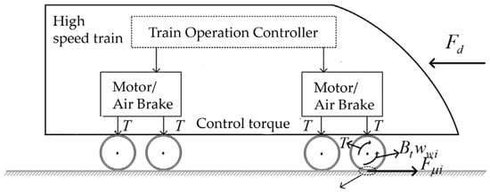
Figure 1.
Train modeling considering adhesion.
For a specific vehicle model, the expression for the basic resistance force can be fitted from wind tunnel tests. However, the parameters of this expression are generally difficult to obtain accurately and may vary with different operating environments. It can be modeled as
where represents the train’s velocity, and M denotes the train’s mass.
According to (2), the adhesive force can be expressed as the product of the coefficient of adhesion and the axial weight :
where is the coefficient of adhesion, represents the axial load, and is the gravitational acceleration.
Experiments have shown that the coefficient of adhesion can be expressed as a function of creep speed and vehicle speed, as described in Equation (6). The creep speed is defined as the difference between the wheel speed and the vehicle speed:
In Equations (6) and (7), , , , and are parameters that need to be set based on different operating conditions. is the Kalker creep coefficient, represents the shear modulus, a and are the long and short semi-axes of the elliptical contact patch, and is the axial load. The longitudinal creep rate is defined by the following equation:
As shown in Figure 1, the traction wheel circumference braking force of the train is provided by the motor, while the braking force of the brake wheels is assumed to be supplied solely by the air brake system. The motor control method used is vector control, although the principles of motor vector control are not discussed in this paper. The air brake is modeled as follows:
where represents the pressure on each brake pad, is the friction coefficient of the brake pad, and denotes the average friction radius of the brake disc. The parameter refers to the working diameter of the brake cylinder, represents the brake cylinder pressure, is the brake clamp multiplier, and is the basic brake transmission efficiency. is the time constant of the brake cylinder for flushing and exhausting.
Equations (9) and (10) represent the braking force generated by the train’s air brake, while Equation (11) provides a simplified model of the train brake cylinder. From the air brake model, it can be inferred that the target brake cylinder pressure is derived from (9), and the actual brake cylinder pressure is regulated by a PI controller to track the desired pressure value. Consequently, the brake system outputs the specified wheel circumference braking force.
As shown in Figure 2, as the braking force applied to the wheel circumference increases, the wheels experience increasing adhesion. When the creep speed approaches the peak adhesion characteristics, the driving force applied to the wheel brings the wheel closer to the rail surface, maximizing adhesion. However, if the driving force continues to increase beyond this point, the wheel–rail adhesion decreases rapidly, leading to wheel slip, which compromises the train’s safety.
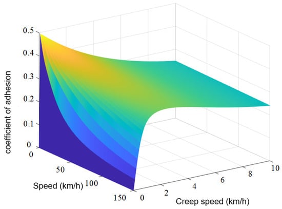
Figure 2.
Adhesion behavior under dry rail surface conditions.
Therefore, it is essential to design a train operation controller that can track the target “velocity–displacement” curve while ensuring that the wheel–rail system operates on the left side of the peak adhesion point. This approach helps avoid wheelset slip and enhances the safety of train operations.
2.2. Train Model Conversion
Assume that the difference between the target wheel circumference braking force transmitted by the train controller to the motor/air brake and the actual wheel circumference braking force output by the motor/air brake is . The output of the train controller is equally distributed to the dynamic axle during traction and to all axles during braking. When the train is in traction, the dynamic axle and trailer axle wheel pair dynamics equations can be re-expressed as
When the train is under braking, the dynamic equations for each axle pair can be expressed as
In Equations (12)–(14), when the train is in traction state () or in braking state (), it can be observed that there is a difference between the target control force output from the train controller to each axle and the actual traction/braking force acquired by the train from each axle during traction or braking. will be used to measure the difference between the actual traction/braking force and the target braking force of each axle of the train during traction/braking due to factors such as inertia, damping, and external disturbances. By substituting the re-expressed dynamic/trailer axle model into the body models (1) and (2), the overall mathematical model of the high-speed train can be represented as
3. Controller Design and Convergence Analysis
3.1. Robust Adhesion Observer
The adhesion between the wheels and rails can be estimated using an observer, with the extended state observer being one of the most commonly used methods. Dividing both sides of (3) by and , and then rewriting the wheel motion equation gives
Therefore, the extended state observer can be designed as
where is the observed value of the wheel speed , and is the observed value of .The functions and are the design functions of the observer, where and are the design parameters of the observer.
By defining , , and , then substituting Equations (16) and (17) into Equation (18) while considering , we obtain the error differential equations:
Traditional extended state observers assume and design and to make the observer error gradually converge to zero, thus observing the system’s state. However, from Equation (20), it can be seen that even if the extended state observer makes , there still exists an observation error in the observer. This indicates that the dynamic observation accuracy of the traditional extended state observer requires improvement. Inaccurate torque estimation can impact the performance of subsequent control strategies. Therefore, it is crucial to design a torque observer that accounts for changes in torque.
Referring to the design flow of the fixed-time robust differentiator, a robust adhesion observer is designed in this section. Under the assumption , the design of and in (17) and (18) is given by Equations (21) and (22). Thus, a robust adhesion observer is constructed:
where is a constant and > 0. In (21) and (22), the terms and act to accelerate the convergence speed when the observer has a relatively large observation error.
Theorem 1.
If and , where L is a positive constant, and if the conditions ,, and > 0, the observer can observe the torque within a finite time.
Proof.
Let , and define the Lyapunov function , where P is a positive definite symmetric matrix. □
From , the following expression can be derived:
Combining Equations (19) and (20), the expression becomes
where , , and .
According to , where L is a positive constant, it follows that .
Letting , the expression becomes
From the analysis above, by deriving and processing , the following result is obtained:
According to Lemma 3.2 from Gahinet and Apkarian (1994) [15] on H-infinity control and Theorem 2.4.3 from Shen Tielong (1996) [16] on the Neutralization Theorem in H-infinity control theory and applications, it follows that .
If A is a stable matrix, i.e., , . The linear matrix inequality Equation (26) has a positive definite symmetric solution P:
where ε is a small positive number. Substituting (26) into Equation (25), the following is obtained:
where is the maximum eigenvalue of matrix P. According to the above equation, the Lyapunov function is negative, meaning the observation error can converge to zero within a finite time. The Lyapunov function has an initial value at time 0. By integrating both sides of Equation (27), the following expression is obtained:
Thus, when = 0, the observation error will converge to zero within . By observing , the torque and its derivative can be calculated. There is no observation error if does not exist.
3.2. Proactive Anti-Diversion Strategies
For a specific train route, the wheel–rail adhesion state can be categorized into five typical conditions, ranging from good to poor. The adhesion characteristics between the wheel and rail under these varying conditions at a fixed speed are illustrated in Figure 3.
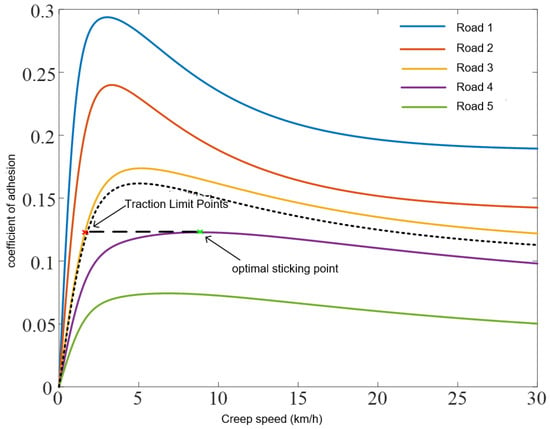
Figure 3.
Adhesion characteristics under different typical road conditions.
Based on the basic theory of adhesion discussed in Section 2.1, it is understood that when the braking force applied to the wheels of a train does not exceed the maximum traction force provided by the adhesion between the wheels and rails, the wheel–rail system operates on the left side of the peak adhesion point, preventing wheelset slip. Therefore, when the train is operating under specific track conditions, the maximum traction force that the rail surface can provide under slightly poorer adhesion conditions can be selected as the control force output to avoid wheel slip. For example, in the case of road condition 3 shown in Figure 3, the controller output is limited by the maximum traction force corresponding to the optimal adhesion point of road condition 4, thereby preventing wheelset slip under the poorer adhesion conditions of road condition 3.
Considering factors such as axle load and environmental elements affecting torque, the actual wheel torque characteristics will inevitably fall within a specific torque characteristic range. For example, the shaded area in Figure 3. In this section, the torque observer is used to obtain the actual wheel torque coefficient . By selecting as the typical road condition that is most similar to the current road condition, the train is actively prevented from slipping by selecting the typical road condition that is a little bit poorer as the output of the train’s maximum traction force limiting controller, where represents the typical condition torque coefficient, and represents the typical condition number from 1 to 5. The researched typical conditions are represented by a 10-segment axis, so comparing the actual torque characteristics to this typical condition will yield a maximum vehicle adhesion force of . is the maximum observed torque coefficient for this condition.
Through the torque characteristic model, the maximum adhesion force can be obtained. The adopted O-Polach torque characteristic model cannot directly calculate the eigenvalue to obtain the maximum torque coefficient , so the calculation of the maximum vehicle adhesion force needs to be continuously approximated to approach the eigenvalue information expressed by the analytical formula. Therefore, this section adopts the approximation method to obtain the maximum torque coefficient for the typical condition closest to the actual observed value and calculates the maximum vehicle adhesion force.
During the implementation process, sensor data (such as wheel speed, traction force sensors, etc.) is used to monitor the adhesion between the wheels and the track, providing real-time feedback to the controller. When insufficient adhesion is detected, the controller immediately adjusts the traction output and limits it to the maximum value determined by the current track conditions. In this way, the controller can quickly respond to external disturbances, ensuring stable operation of the train under low adhesion conditions.
The specific active control strategy can be designed as follows (see Figure 4):
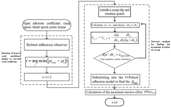
Figure 4.
Flowchart of active anti-short turn strategy.
3.3. Higher-Order Sliding Mode-Based Active Anti-Slip Controller
Traditional sliding mode control often results in large oscillations, which can undermine the stability of the entire vehicle system. To address this issue, higher-order sliding mode theory is introduced. The higher-order sliding mode controller can be designed as follows:
In the above equations, and are determined by the adaptive laws in Equations (30) and (31):
To maintain consistent controller speed, generally assumes a larger value. Based on the analysis in Section 3.2, limiting the controller output to be lower than the maximum adhesion force can prevent wheel slipping and enhance vehicle operational safety. Consequently, the maximum adhesion force derived from the active anti-slip control strategy in Section 3.2 is used to cap the controller output, thereby achieving active anti-slip control. Compared to traditional vehicle controllers, this approach minimizes the impact of wheel torque variations on the controller’s output. The actual controller output is
is defined as , where is the vehicle adhesion characteristic given by Equation (33) represents the control limit derived from the active anti-slip strategy in Section 3.2.
Additionally, the higher-order sliding mode control law incorporates an integral term and includes a parametric adaptive law in integral form. When the anti-slip control strategy and traction characteristics impose limits on the controller output, the convergence of the sliding mode variables may be compromised. As a result, the adaptive and integral components of the control law may increase, potentially affecting the stability of the controller. To address this issue, this section combines the saturation compensation control law with the higher-order sliding mode train controller, ensuring system stability when the controller output is constrained. The train saturation compensation law is designed as follows:
Specifically, the main function of the saturation compensation control law is to prevent the controller output from exceeding the maximum available traction force, thereby avoiding wheel slip. When the train operates under low adhesion conditions, traditional control strategies may lead to outputs exceeding the system’s physical limits, causing instability or slip. The saturation compensation control law corrects the control output in real time to ensure it does not exceed these physical limits.
With the inclusion of the saturation compensation control law, the train sliding mode variables are redefined as follows:
By integrating Equations (29)–(35), the active anti-slip control law can be formulated as
To maintain consistent controller speed, generally assumes a larger value. Based on the analysis in Section 3.2, limiting the controller output to be lower than the maximum adhesion force can prevent wheel slipping and enhance vehicle operational safety. Consequently, the maximum adhesion force derived from the active anti-slip control strategy in Section 3.2 is used to cap the controller output, thereby achieving active anti-slip control. Compared to traditional vehicle controllers, this approach minimizes the impact of wheel torque variations on the controller’s output.
The system is stabilized under the control law in Equations (36)–(38), and the sliding mode variable will converge within a small range defined by . If , the displacement and vehicle speed tracking errors will converge. If , the following condition is satisfied:
Theorem 2.
The position and speed tracking errors and will still converge. The train will then track up the target velocity–displacement curve. Furthermore, the designed controller is capable of providing the maximum vehicle adhesion force, thereby preventing wheel slipping.
Proof.
Taking the derivative of the sliding mode variable and combining the control laws (36)–(39) and the vehicle model (15), the following is obtained:
From Equation (41), the following can be obtained:
where . □
The Lyapunov function is chosen as , where . To facilitate proving the adaptive law, the controller stability is chosen as .
When , and . Combining this with (42), the result is
where and , with . The purpose of reducing in the above equation is to lower , preventing the integral term from becoming excessively high and adversely affecting control performance.
(1) The stability of the controller when is analyzed as follows:
Since , and when
Therefore, . Furthermore, according to
Equation (44) can be simplified as
where .
By substituting the expressions for , , simplifies to
By Shur’s complementary lemma, is a negative definite matrix when the following conditions are satisfied:
Therefore, if satisfies the condition of Equation (49), then , ensuring the system’s stability, and the sliding mode variable will converge to zero. When is not satisfied, the adaptive law for will increase, ensuring .
(2) The following analysis demonstrates that when and , the controllers remain stable. Define the Lyapunov function as
where and are the target values of and , respectively. Satisfying the convergence condition of (49), let and . The derivation of Equation (50) gives:
where . Let and be when and take and . Then, Equation (51) reduces to
Since , , it is possible to calculate:
By substituting Equation (53) and the adaptive law (37) into Equation (52), the following result is obtained:
Since is negatively determined, , and the sliding mode variable converges to the range , ensuring the controller’s stability. By combining the analyses of (1) and (2), the sliding mode variable will converge to the set range under the action of the designed train control law.
The convergence of the displacement and speed tracking errors and is discussed as follows:
- (1)
- Unrestricted controller output
According to the saturation compensation law (34), will converge to 0. For , it follows that converges to a very small neighborhood of the origin, implying that will also converge to a small neighborhood of the origin. As a result, and eventually converge to very small values, enabling the train to track the target velocity–displacement curve.
- (2)
- Controller Output Constrained
When the train controller output is limited and , if (40) is satisfied, , meaning will eventually converge to zero. Since and are almost zero when the controller output is constrained, will converge to a small value , ensuring sufficient dynamic performance of the saturation compensation law. Eventually, and converge to very small values, allowing the train to track the target velocity–displacement curve.
4. Experiment Results
To closely integrate the adhesion control algorithm with practical applications, the algorithm is implemented on the DSP controller, and the train model is downloaded to the ModelingTech semi-physical simulation platform using STAR-SIM software, whose version number is 4.6.2.9. This setup creates a DSP-ModelingTech Hardware-in-the-Loop experimental platform to validate the effectiveness of the proposed algorithm. It is important to note that the output from the semi-physical platform, ModelingTech, contains a certain level of noise. For a visual representation of the experimental process, please refer to Figure 5.
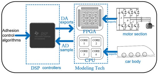
Figure 5.
Experimental flowchart.
The train used in this study is an eight-car high-speed train with a 5M3T configuration, where five of the cars are equipped with powered axles, totaling ten moving axles. For a visual reference of the actual train, please refer to Figure 6. The CCS software version used in related simulations or operations is 8.1.0.00011.The simulation parameters for the high-speed train body model are detailed in Table 1. The motor parameters are sourced from [17], and the air braking parameters are provided in [18].
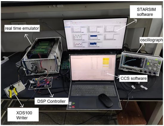
Figure 6.
Actual picture.

Table 1.
Train parameters.
The train operates under different road conditions as follows: from 0 to 115 s, the train runs on dry road conditions; from 115 to 120 s, on icy road conditions; from 120 to 170 s, on oily road conditions; from 170 to 320 s, on wet road conditions; and from 320 to 533 s, on very wet road conditions. The output of the train controller under snowy and icy conditions exceeds the maximum traction force that the current track surface can provide. Without corrective action, the wheelset may begin to slip.
The operating conditions of the train are shown in Table 2. The relevant parameters of the O-Polach model for each simulated road condition are presented in Table 3.

Table 2.
Train operating conditions.

Table 3.
Parameters of the simulated track surface.
To evaluate the performance of the proposed control method, we conducted experiments and compared it with common control techniques, such as Model Predictive Control (MPC), Robust Control, and PID control. The key metrics include tracking accuracy (RMSE and maximum error), computational efficiency (execution time), and control response time. These metrics are essential for assessing the real-time feasibility and accuracy of the control algorithm. For a detailed comparison of the performance based on key metrics, please refer to Table 4.

Table 4.
Performance comparison of control methods in low-adhesion train control.
In addition to traditional sliding mode control, adaptive sliding mode control based on disturbance compensation is implemented on the Hardware-in-the-Loop platform to compare the control effects. The specific parameters for each controller are detailed in Table 5.

Table 5.
Controller parameters.
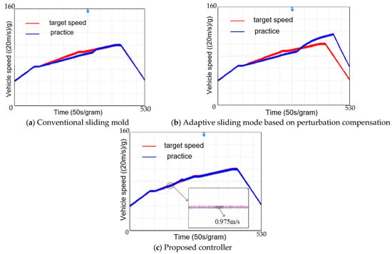
Figure 7.
Speed tracking effect comparison chart.
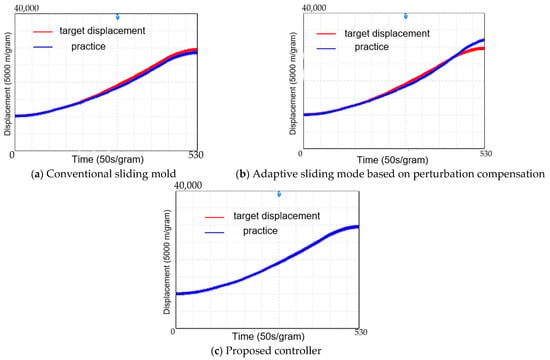
Figure 8.
Comparison of displacement tracking effect.
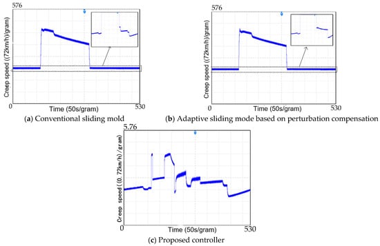
Figure 9.
Comparison chart of creep and slide speed.
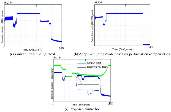
Figure 10.
Controller output comparison chart.
Figure 7 and Figure 8 compare the speed and displacement tracking effects under different control strategies. When the train encounters icy or oily road conditions, the wheelsets tend to slip because the output of the train’s conventional sliding mode controller and the adaptive sliding mode controller based on perturbation compensation exceeds the maximum traction force that can be generated between the wheels and rails. This slip leads to a rapid and significant reduction in adhesion, causing the train to lose traction. As a result, the displacement tracking errors and speed tracking errors of the train increase significantly, as shown in Figure 7 and Figure 8 (plots a and b).
After 320 s, when the train transitions into wet road conditions, the braking force exerted by the motor on the wheels becomes smaller than the adhesion force, thereby restoring adhesion between the wheels and rails. As a result, the conventional sliding mode control reduces the tracking errors in both speed and displacement. However, the adaptive sliding mode control based on perturbation compensation fails to maintain accurate tracking of the target curve once adhesion is restored, due to the cumulative error of its internal integral term, which ultimately leads to controller failure.
In contrast, Figure 7c and Figure 8c demonstrate that the higher-order sliding mode-based active anti-slip control designed in this study achieves the smallest tracking errors in both speed and displacement. This effectiveness is attributed to the controller’s strategy of selecting a typical road condition with slightly worse adhesion than the current conditions. By utilizing the active anti-slip strategy, the controller calculates the maximum traction force available and employs Newton’s iterative method to appropriately limit the controller’s output. Consequently, the wheel–rail system consistently operates within the adhesion state, avoiding wheelset slip and preventing significant traction loss.
Figure 9 presents the creep-slip velocity graphs during the process of controlling the train to track the target velocity–displacement curve using different controllers. As shown in plots (a) and (b) of Figure 9, under conventional sliding mode control and adaptive sliding mode control based on perturbation compensation, the lack of an anti-slip strategy results in the creep speed exceeding 200 km/h after the train enters icy road conditions at 115 s, leading to noticeable wheelset slip.
The variation in the vertical axis of Figure 9c demonstrates that with the designed controller, the creep-slip speed remains between −0.72 and 2.88 km/h, effectively preventing slip. The observed variation in creep speed in plot (c) is attributed to the switching of road conditions or the controller output adjustments, ensuring that the wheel–rail system operates within a stable range and preventing significant traction loss.
Figure 10 illustrates the output of each controller. In this study, we communicate with the real-time simulator via analog signals, converting the controller outputs to single-axis braking forces, which are then adjusted to the DA output range by a specific scale factor. To prevent DA saturation, upper and lower limits for the controller outputs are set separately. Therefore, when wheel slip occurs in the train, the control output is constrained after 115 s in Figure 10a,b.
Figure 10c demonstrates that when the train encounters icy, snowy, and oily low-viscosity road conditions between 115 and 170 s, the designed active anti-slip strategy effectively limits the controller output, ensuring that it does not exceed the maximum traction force that the current rail surface can provide, thereby preventing wheel slip. It is important to note that the proposed controller output limitation incorporates both the anti-slip strategy and the traction characteristics, resulting in a more reasonable controller output.
Additionally, the output limitation anomaly observed between 200 and 250 s in Figure 10c is due to the adhesion coefficient approaching zero when the control law is near zero. In such scenarios, the road conditions are very similar to those near the adhesion coefficient of zero. The accuracy of the active anti-slip strategy in selecting the appropriate typical road conditions similar to the current road conditions decreases, leading to the observed output limitation anomaly.
5. Discussion
This study presents a novel train anti-slip control method tailored for low-adhesion conditions, offering significant improvements over traditional approaches. While the use of a linear adhesion model simplifies the analysis, it does not fully capture the nonlinear nature of real-world adhesion, especially under adverse weather and complex track conditions. This simplification may reduce the model’s accuracy in practical applications. To enhance the system’s adaptability and precision, future research should focus on exploring more sophisticated, nonlinear adhesion models.
Moreover, the reliance on laboratory-based data and theoretical models limits the generalizability of the findings. Future research should integrate real-world operational data to improve the robustness and applicability of the proposed control strategy. Although semi-physical Hardware-in-the-Loop (HIL) experiments are valuable for testing control systems, they cannot fully replicate the complexities of real-world conditions, such as rail contamination, wheel wear, and dynamic load variations. These factors may affect the performance of the proposed method. Therefore, future work should focus on bridging the gap between HIL testing and real-world applications by incorporating more realistic simulation models and operational data.
6. Conclusions
In this paper, we address the issue of wheelset slip caused by the train controller output exceeding the maximum traction force available on low-adhesion track surfaces as the train enters these conditions. To mitigate this, an active anti-slip strategy is designed to limit the train controller output. Furthermore, to reduce the impact of output chattering from traditional sliding mode control on system stability, a higher-order sliding mode train controller is developed. Considering the effect of output limitations on controller stability, a saturation compensation control law is incorporated to further enhance the higher-order sliding mode controller. The result is an active anti-slip controller based on higher-order sliding mode. Experimental results demonstrate that the proposed controller effectively prevents wheelset slip and minimizes tracking errors to the target curve, especially under conditions where the train encounters low maximum traction force due to a low-adhesion rail surface. The proposed method outperforms both traditional sliding mode control and adaptive sliding mode control based on perturbation compensation.
Author Contributions
Software, S.C.; validation, B.Z.; investigation, S.W. and S.C.; resources, S.W.; data curation, B.Z.; writing—original draft, S.W.; writing—review and editing, S.W.; visualization, Y.W.; supervision, Y.W. All authors have read and agreed to the published version of the manuscript.
Funding
This research was funded by Academy of Railway Sciences Group Company grant number 2023YJ371 and National Natural Science Foundation of China grant number U21A20169.
Institutional Review Board Statement
Not applicable.
Informed Consent Statement
Not applicable.
Data Availability Statement
The original contributions presented in this study are included in the article. Further inquiries can be directed to the corresponding author.
Conflicts of Interest
The authors declare that this study received funding from Academy of Railway Sciences Group Company. The funder was not involved in the study design, collection, analysis, interpretation of data, the writing of this article or the decision to submit it for publication.
References
- Novak, H.N.; Lešić, V.; Vašak, M. Energy-efficient model predictive train traction control with incorporated traction system efficiency. IEEE Trans. Intell. Transp. Syst. 2021, 23, 5044–5055. [Google Scholar] [CrossRef]
- Li, S.; De Schutter, B.; Yang, L.; van den Boom, T. Robust model predictive control for train regulation in underground railway transportation. IEEE Trans. Control. Syst. Technol. 2015, 24, 1075–1083. [Google Scholar] [CrossRef]
- Huang, D.; Chen, Y.; Meng, D.; Hu, Y. Adaptive iterative learning control for high-speed train: A multi-agent approach. IEEE Trans. Syst. Man Cybern. Syst. 2019, 51, 4067–4077. [Google Scholar]
- Yao, X.; Li, S.; Li, X. Composite adaptive anti-disturbance fault-tolerant control of high-speed trains with multiple disturbances. IEEE Trans. Intell. Transp. Syst. 2022, 23, 21799–21809. [Google Scholar]
- Mao, Z.; Yan, X.G.; Jiang, B.; Chen, W. Adaptive fault-tolerant sliding-mode control for high-speed trains with actuator faults and uncertainties. IEEE Trans. Intell. Transp. Syst. 2019, 21, 2449–2460. [Google Scholar]
- Wu, P.; Wang, Q.Y.; Feng, X.Y. Automatic train operation based on adaptive terminal sliding mode control. Int. J. Autom. Comput. 2015, 12, 142–148. [Google Scholar]
- Zheng, J.; Hou, Z. ESO-based model-free adaptive iterative learning energy-efficient control for subway train with disturbances and over-speed protection. IEEE Trans. Intell. Transp. Syst. 2023, 24, 8136–8148. [Google Scholar]
- Yang, X.; Li, X.; Ning, B.; Tang, T. A survey on energy-efficient train operation for urban rail transit. IEEE Trans. Intell. Transp. Syst. 2016, 17, 2–13. [Google Scholar]
- Yang, H.; Zhang, K.P.; Liu, H.E. Online regulation of high speed train trajectory control based on t-s fuzzy bilinear model. IEEE Trans. Intell. Transp. Syst. 2015, 17, 1496–1508. [Google Scholar] [CrossRef]
- Wu, B.; Wen, Z.; Wang, H. Numerical analysis on wheel/rail adhesion under mixed contamination of oil and water with surface roughness. Wear 2014, 314, 140–147. [Google Scholar]
- Kalker, J.J. Wheel-rail rolling contact theory. Wear 1991, 144, 243–261. [Google Scholar]
- Polach, O. Creep forces in simulations of traction vehicles running on adhesion limit. Wear 2005, 258, 992–1000. [Google Scholar]
- Huang, D.; Yang, W.; Huang, T. Iterative learning operation control of high-speed trains with adhesion dynamics. IEEE Trans. Control. Syst. Technol. 2021, 29, 2598–2608. [Google Scholar]
- Yao, X.; Zhao, B.; Li, S. Disturbance Observer-Based Tracking Control of High-Speed Trains Under Adhesion Dynamics. IEEE Trans. Autom. Sci. Eng. 2023, 21, 1727–1739. [Google Scholar] [CrossRef]
- Gahinet, P.; Apkarian, P. A linear matrix inequality approach to H∞ control. Int. J. Robust Nonlinear Control. 1994, 4, 421–448. [Google Scholar] [CrossRef]
- Shen, T. H∞ Control Theory and Applications; Tsinghua University Press: Beijing, China, 1996. [Google Scholar]
- Xiong, S. Research on Traction Converter of CRH5 EMU. Master’s Thesis, Southwest Jiaotong University, Chengdu, China, 2013. [Google Scholar]
- Zhao, W. Modeling and Braking Characteristics Study of Train air Brake System. Master’s Thesis, Southwest Jiaotong University, Chengdu, China, 2020. [Google Scholar]
Disclaimer/Publisher’s Note: The statements, opinions and data contained in all publications are solely those of the individual author(s) and contributor(s) and not of MDPI and/or the editor(s). MDPI and/or the editor(s) disclaim responsibility for any injury to people or property resulting from any ideas, methods, instructions or products referred to in the content. |
© 2025 by the authors. Licensee MDPI, Basel, Switzerland. This article is an open access article distributed under the terms and conditions of the Creative Commons Attribution (CC BY) license (https://creativecommons.org/licenses/by/4.0/).