Article

Ultrasonic Evaluation Method for Mechanical Performance Degradation of Fluororubber Used in Nuclear Power Facility

1
School of Mechanical Engineering, Zhejiang University, Hangzhou 310027, China
2
Computer Application Institute of Nuclear Industry, China National Nuclear Corporation, Beijing 100822, China
3
Hainan Nuclear Power Co., Ltd., China National Nuclear Corporation, Haikou 570125, China
*
Author to whom correspondence should be addressed.
Appl. Sci. 2025, 15(7), 3903; https://doi.org/10.3390/app15073903
Submission received: 10 February 2025 / Revised: 15 March 2025 / Accepted: 31 March 2025 / Published: 2 April 2025
(This article belongs to the Section Applied Physics General)

Abstract

:
Fluororubber sealing products are widely used in nuclear power equipment, and the degree of degradation of their mechanical properties directly affects the sealing performance, which in turn affects the overall safety of nuclear power units. In order to quantitatively evaluate the degradation of the mechanical properties of fluororubber, the theory of ultrasonic propagation in fluororubber was studied. A second-order generalized Maxwell viscoelastic model was constructed in a small strain scenario of high-frequency harmonic vibration to describe the correlation between the mechanical properties and acoustic parameters. A nondestructive evaluation method for mechanical performance degradation using ultrasonic waves based on the nonlinear fitting of the model parameters was proposed. A control experiment was designed using O-rings that had been in service and those that had not yet been used in nuclear power, and mechanical tensile tests and electron microscopy microscopic analyses were conducted. The results showed that the overall elastic modulus of the used sealing ring (2.97 ± 0.15 GPa) was significantly higher than that of the unused sealing ring (2.75 ± 0.22 GPa), consistent with the results of the mechanical tensile tests. However, the sound attenuation coefficient of the unused sealing ring was significantly higher than that of the used sealing ring. Therefore, the ultrasonic evaluation of the mechanical performance degradation of fluororubber based on the viscoelastic model is a nondestructive testing method with engineering application potential.

1. Introduction

Fluororubber is a type of synthetic rubber containing fluorine atoms, offering excellent weather fastness, electrical insulation, radiation resistance, and mechanical properties. It also outperforms conventional rubbers in high-temperature resistance, oil resistance, and resistance to various chemical agents. As such, it is an indispensable advanced sealing material in the nuclear power industry [1]. Nuclear fluororubber sealing materials require excellent mechanical properties including elasticity, tensile strength, abrasion resistance, and low gas permeability. However, exposure to high temperature, high humidity, and irradiation in the service environment can accelerate the cleavage and reorganization of C = O and C H 2 = C F ( C F 3 ) bonds within the molecular chains, leading to the degradation of the mechanical properties of the fluororubber. Ultimately, this degradation can result in a reduced compression set ratio, which can cause leakage in sealing products [2]. Implementing a nondestructive quantitative evaluation of the mechanical property degradation of nuclear-grade fluororubber and predicting the sealing performance and service life of in-service or stored sealing components play a crucial role in preventing accidents caused by leakage.
Currently, the main methods for predicting rubber performance degradation and service life include traditional kinetic methods, computer simulation prediction methods, and constitutive model methods [3]. The kinetic method based on the Arrhenius model is used to fit empirical kinetic equations by using experimentally obtained aging data with aging times. It also uses the Arrhenius equation to establish the relationship between the aging reaction rate constants at different temperatures.
This life prediction method has certain limitations in practical applications. Carolina C.M. et al. [1] standardized the chemical, mechanical, and thermal stability under the testing conditions of the Arrhenius method. Alireza employed finite element analysis based on fundamental material properties such as viscoelasticity, hyperelasticity, and chemical degradation, combined with compression stress relaxation performance, to predict the sealing performance of elastomer components under real-world conditions. The constitutive model method involves establishing the “stress–strain” relationship of rubber to simulate its performance changes during the aging process, thereby predicting the service life under different stress levels [4]. For example, Korba, A. G. proposed an empirical constitutive hyperelasticity model that takes into account the effects of aging temperature and time on its parameters, which can effectively reduce the need for mechanical property testing experiments.
There are various nondestructive testing techniques for rubber materials including X-ray radiographic inspection, thermography, laser speckle interference, nuclear magnetic resonance, terahertz imaging, ultrasonic testing, and so on [5,6,7]. Among these, ultrasonic nondestructive testing uses ultrasonic waves as the carrier, which are mechanical waves. The acoustic properties of these waves, such as time-domain signals, sound velocity, attenuation, impedance, and scattering, have a direct correlation with the material’s mechanical properties (e.g., elastic modulus, shear modulus, and viscoelasticity) as well as its microstructure [8,9]. This makes ultrasonic testing one of the most promising nondestructive methods for evaluating the mechanical properties of rubber.
Ultrasonic testing has proven to be an effective nondestructive evaluation technique for detecting defects and assessing material degradation due to its sensitivity to changes in mechanical properties [10]. Traditional linear ultrasonic methods, which rely on sound velocity and attenuation coefficients, are effective for determining the elastic properties of materials and identifying macroscopic defects [11,12,13]. However, these methods are limited in their ability to detect damage before the onset of crack formation [14]. In contrast, nonlinear ultrasonic testing is particularly adept at detecting subtle defects by analyzing waveform distortions during sound wave propagation through materials without causing damage. When a defect is present, the stress–strain relationship at the defect site deviates from Hooke’s law, transitioning from linear to nonlinear behavior. This nonlinearity generates distortions, often manifesting as higher-order harmonics, under high-frequency and high-energy ultrasonic excitation. The cumulative effect of these micro-disturbances from multiple defects leads to the overall distortion of the ultrasonic waveform, which can be quantitatively characterized by examining the amplitude of the higher harmonic components. Initially applied to metallic materials [15], nonlinear ultrasound techniques have expanded to nonmetallic materials in recent years. For example, studies on the epoxy curing process [16] have demonstrated that nonlinear ultrasound is sensitive to changes in the curing degree, with alterations in the second and third harmonic components reflecting changes in the material’s mechanical properties. Additionally, research on physical and thermal aging in polymers indicates that nonlinear ultrasonic distortion can serve as an early indicator of material aging [17].
Previous studies have utilized the nonlinearity of ultrasonic wave propagation, specifically the generation of high-frequency harmonic parameters, in single-crystal and polycrystalline metals. This phenomenon is more sensitive to material fatigue life, tensile property degradation, creep damage, and interface bonding strength, among other factors, and has been applied to characterize the early-stage performance degradation of metallic materials. Domestic researchers have also introduced nonlinear acoustics into the performance evaluation of rubber materials. Some researchers have presented an efficient method for assessing the aging degradation of rubber using the quasi-static component (QSC) of ultrasonic longitudinal waves induced by acoustic radiation, and their experiments quantitatively observed the response of the QSC pulse to different levels of aging degradation [18]. Some researchers have conducted thermal aging experiments on silicone rubber, measuring the nonlinear coefficient using nonlinear ultrasonic methods during the aging process. They analyzed the changes in the nonlinear coefficient to investigate the thermal aging behavior and assessed the feasibility of using the nonlinear coefficient as an indicator of the aging of silicone rubber [19]. However, the presented characterizations struggle to establish a direct correlation with the mechanical property parameters [7]. In this paper, our work begins with the ultrasonic propagation phenomenon in fluororubber and constructs an appropriate viscoelastic constitutive model to describe the relationship between the mechanical properties and acoustic parameters. Based on this, a nondestructive ultrasonic evaluation method for mechanical property degradation is proposed, which involves the inversion of the constitutive model parameters.

2. Methods

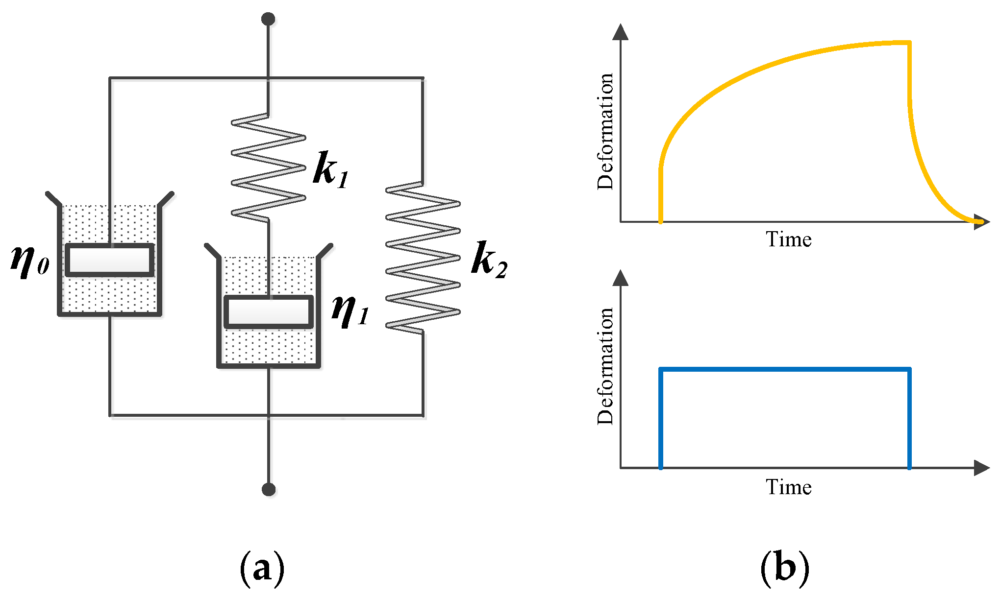
2.1. Viscoelastic Model for Acoustic Wave Propagation

2.1.1. Viscoelastic Model Construction of Fluororubber

The mechanical properties of rubber are commonly described using phenomenological approaches based on continuum mechanics, treating rubber as an isotropic hyperelastic material.
Existing rubber constitutive models, such as Mooney–Rivlin, neo-Hookean, Yeoh, Ogden, and Arruda–Boyce, describe the stress–strain relationship of rubber under large strains ( ε > 30 % ). However, the elastic response of rubber under small strains ( ε < 5 % ) is essentially Hookean [6,20]. Therefore, hyperelastic constitutive models are not suitable for harmonic vibrations at ultrasonic frequencies. The direction of the long molecular chains of fluororubber is randomly distributed, so it is also regarded as an isotropic material. Its stress–strain relationship is described according to the generalized Hooke’s law as:
σ 11 σ 22 σ 33 σ 12 σ 23 σ 31 = K + 4 3 G K 2 3 G K 2 3 G 0 0 0 K 2 3 G K + 4 3 G K 2 3 G 0 0 0 K 2 3 G K 2 3 G K + 4 3 G 0 0 0 0 0 0 G 0 0 0 0 0 0 G 0 0 0 0 0 0 G ε 11 ε 22 ε 33 γ 12 γ 23 γ 31
where K represents the material bulk modulus and G represents the material shear modulus.
Ultrasonic waves in fluororubber experience rapid attenuation, dispersion, and backscatter phenomena. Therefore, the constitutive model needs to account for the viscosity coefficient and the relaxation processes of the internal microstructure.
Considering all factors, as shown in the Figure 1a, this paper treated it as a viscoelastic medium that is uniform in the depth direction and follows the generalized Maxwell model. The choice of a modified Maxwell model consisting of a spring, dashpot, and a parallel spring-dashpot combination was made to better capture the viscoelastic behavior of fluororubber under small-strain conditions. This model effectively accounts for both the elastic and viscous components of the material’s response, which is essential to accurately model ultrasonic wave propagation and attenuation. The parallel spring-dashpot configuration is more suitable than the standard series arrangement as it allows for a detailed representation of the frequency-dependent damping and elasticity observed in fluororubber during ultrasonic testing. This modification ensures that the model can better describe the material’s behavior in high-frequency, small-strain scenarios typically encountered in ultrasonic nondestructive evaluation. The governing equation for the stress–strain response is then given by:
η 0 η 1 d 2 ε d t 2 + k 1 η 1 + k 2 η 1 + k 1 η 0 d ε d t + k 1 k 2 ε = η 1 d σ d t + k 1 σ
where k 1 is the stiffness coefficient of spring 1 in Figure 1a, k 2 is the stiffness coefficient of spring 2, and η 0 and η 1 correspond to the viscosity coefficients of viscous element 0 and viscous element 1, respectively. The equation describes a viscoelastic system involving a fluororubber mechanical structure that is subject to both elastic and viscous forces. The first derivative of strain d ε d t indicates the rate of deformation, while the second derivative d 2 ε d t 2 shows how the material’s deformation is accelerating or decelerating. The term involving stress d σ d t reflects how changes in stress impact the system over time. The model includes both the shear viscosity coefficient η and volumetric viscosity coefficient η , and these are unified and represented as η 1 . According to Equation (1), this can be expressed as η 1 = 4 3 η + η .
In the field of ultrasonic research, all field variables (displacement, stress, strain) are represented as harmonic functions of time. Therefore, the expression is given by:
ε = ε ^ i ω t , σ = σ ^ i ω t
Substituting Equation (3) into Equation (2), the viscoelastic model of fluororubber can be expressed as:
σ ^ = k 1 + k 2 τ 2 ω 2 + k 2 τ 2 ω 2 + 1 + η 0 τ 2 ω 2 η 0 + η 1 τ 2 ω 2 + 1 ω i ε ^
where τ = η 1 / k 1 .
In this model, the elastic modulus exists in a complex form and is frequency dependent. The real part of the elastic modulus represents the energy storage capacity, while the imaginary part represents the energy dissipation capacity.

2.1.2. Physical Interpretation of the Model

The ratio σ ^ / ε ^ is treated as the Hookean elastic modulus C 11 . From Equation (1), it is easy to know that C 11 = K + 4 3 G . This leads to the derivation of the quasi-longitudinal wave velocity in fluororubber as follows:
c l = K + 4 3 G ρ = k 1 + k 2 τ 2 ω 2 + k 2 τ 2 ω 2 + 1 ρ 1 + η 0 τ 2 ω 2 η 0 + η 1 k 1 + k 2 τ 2 ω 2 + k 2 ω i
where ρ is the density of fluororubber. Let K s = k 1 + k 2 τ 2 ω 2 + k 2 τ 2 ω 2 + 1 and H = η 0 τ 2 ω 2 η 0 + η 1 k 1 + k 2 τ 2 ω 2 + k 2 , then the complex form of the quasi-longitudinal wave velocity is given by:
c l = K s ρ 1 + ω 2 H 2 + 1 2 + 1 + ω 2 H 2 1 2 i
The term K s ρ is the initial phase velocity based on elastic properties (like in an ideal elastic material).
The complex part inside the parentheses, involving the frequency ω and the characteristic parameter H , accounts for the viscoelastic nature of the medium, influencing both the wave’s speed and how it is attenuated over time. This equation is useful for analyzing wave propagation in viscoelastic structures, like fluororubber in this paper. The quasi-longitudinal wave number k l = ω / c l , which implies that the wave number in fluororubber material also exists in a complex form. Assuming a plane wave propagates along the depth direction in the fluororubber specimen, the sound pressure of this plane wave can be simply described as [21]:
p t , z = p a e i ω t k l z = p a e i ω t z ρ 1 + ω 2 H 2 + 1 2 K s 1 + ω 2 H 2 e ω z ρ 1 + ω 2 H 2 1 2 K s 1 + ω 2 H 2
When β = ω ρ 1 + ω 2 H 2 1 2 K s 1 + ω 2 H 2 , it can be seen that the amplitude of ultrasonic wave propagation in the fluororubber material decays according to e β z from Equation (7).
The above model starts with the “stress–strain” relationship derived from mechanical tests such as tension, compression, and torsion, and extends this to the domain of simple harmonic vibration. In this model, η 0 is temperature sensitive and is used to describe the equilibrium stress-temperature behavior of fluororubber. In ultrasonic propagation, η 0 is used to characterize the thermal conduction absorption component of fluororubber, η 1 represents the viscosity coefficient of fluororubber, τ is used to describe the relaxation time, k 1 is used to describe the elastic stress resulting from the crosslinking degree and network integrity of the macromolecular chains within the rubber, k 2 represents the effect of filler particles in rubber on the elastic modulus, and k 2 / k 1 + k 2 represents the reinforcement factor of the filler. According to the equation of K s , it is known that when the angular frequency ω is sufficiently large, k 1 + k 2 represents the magnitude of the stiffness coefficient and can be used to describe the reference sound velocity. From Equation (6), it can be seen that the sound velocity depends on the frequency, which explains the phenomenon of ultrasonic dispersion in fluororubber. Therefore, the model can handle viscoelastic problems such as creep and relaxation, and it is also capable of explaining characteristics such as ultrasonic attenuation and frequency shift.
Equations (1)–(7) unify acoustic parameters such as sound velocity and sound attenuation with the mechanical properties. This forms the fundamental principle through which this paper achieved the characterization of the mechanical properties of fluororubber using ultrasonic measurement methods.

2.2. Measuring Principle

Although the above model establishes a mathematical mapping between the acoustic parameters and mechanical properties, the significant coupling relationships among the parameters make it challenging to accurately determine the values of η 0 , η 1 , k 1 , and k 2 through either basic mechanical experiments or traditional ultrasonic measurement experiments. Based on the viscoelastic constitutive model of fluororubber, a backscatter attenuation coefficient was introduced, and a simplified acoustic evaluation model was proposed. The paper also provides specific measurement methods for this model.

2.2.1. Acoustic Evaluation Model

In the offline ultrasonic measurement experiment, the fluororubber specimen was immersed in an ultrasonic couplant, and the ultrasonic propagation within the specimen can be described using a simple layered structure.
As shown in Figure 2, both the probe and the specimen were immersed in the couplant. The couplant above the fluororubber layer was treated as a separate layer and labeled as L0, the fluororubber layer was labeled as L1, and the couplant below the fluororubber layer was labeled as L2. The corresponding interfaces were labeled as IF0, IF1, and IF2. A series of convolutions was used here to describe the ultrasonic echo signals received by the probe from each layer. The specific description is as follows:
f t , 0 = E t h 0 a t h 0 r t + h 0 s t h 0 a t h 0 s t R t A δ t  
f t , 1 = E t h 0 a t h 0 r t + h 0 s t h 1 a t h 1 r t + h 1 s t h 1 a t u 0 r t + h 1 s t h 0 a t h 0 s t R t A δ t
Equation (8) represents the echo signal from the couplant–fluororubber interface (the 0th interface), while Equation (9) represents the echo signal from the fluororubber–couplant interface (the 1st interface). In the two equations, E t represents the impulse response of the ultrasound probe to an electrical pulse, R t is the impulse response of the ultrasound probe to an acoustic pulse, h n a t denotes the one-way attenuation factor of the n-th layer to the ultrasound, h n r t represents the reflection impulse response at the n-th interface, h n s t represents the one-way scattering response of the n-th layer to the ultrasound, and u n r t and u n r t are the return reflection impulse response at the interface and an impulse function with an amplitude of A, respectively. In Equation (8), first, the signal is transmitted through the couplant layer h 0 a t . Then, the signal is reflected back from the probe–couplant interface h 0 r t and passed through the layer again h 0 s t , interacting with the interface IF1. Finally, the reflection and scattering terms combine with the reflection coefficient R t , representing the echo signal at the probe. In Equation (9), the signal is transmitted through the couplant layer L0, reflected at the probe–couplant interface. Then, the signal passes through the fluororubber layer (L1), where it is reflected and transmitted at the couplant–fluororubber interface (IF1) and the fluororubber–couplant interface (IF2). The multiple convolutions describe the complex interactions of the wave as it passes through the different layers and interfaces including scattering, reflection, and transmission.
Taking the Fourier transform of both sides of Equation (8), we obtain:
F ω , 0 = E ω H 0 a ω H 0 r ω + H 0 s ω H 0 a ω H 0 s ω R ω A Δ ω
When using a couplant with known properties (typically water), H 0 a ω and H 0 s ω are known quantities. When the experimental parameters and conditions of use are constant, E ω , R ω , and A Δ ω are then invariant. In the above equation, H 0 r ω is the reflection coefficient spectrum of fluororubber with respect to the couplant, which is related to the material and acoustic properties of fluororubber. Equation (10) shows how the frequency-domain echo signal F ω , 0 is related to the input signal E ω and the material properties of the layers and interfaces and involves the Fourier transforms of the transmitted and reflected signals, the reflection coefficient R ω , and the Dirac delta function A Δ ω . Its expression can be extended using the reflection coefficient formula for the liquid–solid interface as follows [22]:
H 0 r θ , ω = Z l ω cos 2 2 θ s + Z s ω sin 2 2 θ s Z Z l ω cos 2 2 θ s + Z s ω sin 2 2 θ s + Z
where
Z l ω = ρ c l cos θ l , Z s ω = ρ c s cos θ s , Z = ρ 0 c 0 cos θ
where ρ 0 is the density of the couplant, c 0 is the velocity of sound in the couplant, and c l and c s are the longitudinal and shear wave velocities in the fluororubber specimen, respectively. θ is the incident angle of the sound wave from the coupling fluid to the liquid–solid interface, while θ l and θ s are the refracted angles of the longitudinal and shear waves, respectively, in the fluororubber specimen. Equation (11) provides the reflection coefficient spectrum H 0 r θ , ω for the fluororubber layer relative to the couplant and is a function of the acoustic impedances of the materials, the angle of incidence, and the frequency ω . Substituting Equation (6) into the above Equation, we obtain:
Z l ω = ρ K s cos θ l 1 + ω 2 H 2 + 1 2 + 1 + ω 2 H 2 1 2 i
Equation (12) describes the acoustic impedance Z l ω of the couplant layer at frequency ω , incorporating both the material properties (density ρ and stiffness K s ) and the characteristic parameter H . By introducing the Poisson’s ratio v of fluororubber, the shear wave velocity c s can be obtained through the relationship between the bulk modulus K and the shear modulus G. The detailed derivation is omitted here.
F ω , 1 = E ω H 0 a ω H 0 r ω + H 0 s ω H 1 a ω H 1 r ω + H 1 s ω H 1 a ω U 0 r ω + H 1 s ω H 0 a ω H 0 s ω R ω A Δ ω
Equation (13) describes the frequency-domain echo signal F ω , 1 as it propagates through multiple layers, reflecting and transmitting between each interface. Each term represents the wave’s interaction with the material layers (couplant and fluororubber), incorporating the reflection and scattering coefficients at each interface. The presence of Fourier transforms for all terms indicates that this is a model for analyzing the system in the frequency domain. The equation involves multiple convolutions of the signals, representing how the ultrasonic signal is modified by the material properties and interfaces it encounters.
As seen in the propagation model shown in Figure 2, when only the case of the vertical incidence of sound waves θ = 0 ° is considered, in the above expression:
H 0 r ω + H 1 r ω = 1 U 0 r ω = H 1 r ω
Equation (14) provides a relationship between the reflection coefficients at different interfaces in the layered medium. The sum of the reflection coefficients at the two interfaces must equal 1, and the reflected signal from the fluororubber layer is equal to the reflection coefficient at the fluororubber–medium interface. The description of the scattering response h n s t can be approached using several common models including the non-homogeneous continuous model, the separated scattering submodel, and the average rule scattering model [23]. Considering the feasibility of ultrasonic measurement and evaluation, the backscatter coefficient spectrum H 1 s ω was designed as a coefficient related to the layer thickness:
H 1 s ω = e β ω d
where d is the thickness of the medium. For a known specimen, d is a known quantity. Equation (15) models the backscatter coefficient spectrum H 1 s ω as an exponential function of both the frequency ω and the thickness d of the medium. The material-dependent coefficient β characterizes how the medium scatters or attenuates ultrasonic waves.
Thus, an acoustic evaluation model was constructed consisting of three indicators: K s , H , and β , where K s is used to assess the elastic modulus of fluororubber, H is used to evaluate the rebound or compressive recoverability, and β is used to assess the degree of crosslinking and fracture within the fluororubber.

2.2.2. Measurement of Ultrasonic Reflection Coefficient

In the above acoustic evaluation model, the measurement of the reflection coefficient spectrum H 0 r θ , ω of the fluororubber to the couplant is the key for quantifying the three metrics K s , H , and β . From Equation (10), it can be seen that the ultrasonic probe’s impulse response function to the electrical pulse E ω and the impulse response function to the acoustic pulse R ω in the ultrasonic measurement system are difficult to quantify.
Under the same experimental parameters and conditions, E ω , R ω , and A Δ ω are invariants. Therefore, a reference specimen with known material properties and acoustic parameters can be used, allowing Equation (10) to be written as:
F ω , 0 r e f = E ω H 0 a ω H 0 r ω r e f + H 0 s ω H 0 a ω H 0 s ω R ω A Δ ω
Equation (16) represents the ultrasonic measurement of the reference specimen, where F ω , 0 r e f is the Fourier transform of the echo signal from the reference specimen. The equation incorporates the electrical and acoustic impulse responses E ω and H 0 a ω , the reflection and scattering coefficients of the reference specimen, and the system’s impulse response function R ω . This provides a baseline measurement for comparison with the unknown specimen. It can be further derived that:
F ω , 0 F ω , 0 r e f = H 0 r ω + H 0 s ω H 0 r ω r e f + H 0 s ω
In the above equation, F ω , 0 and F ω , 0 r e f can be obtained by performing a Fourier transform on the first interface echo obtained from the ultrasonic measurement experiment, H 0 r ω r e f can be calculated based on the material properties and acoustic parameters, and H 0 s ω can be determined experimentally. It compares the echo signals from the unknown specimen and the reference specimen by calculating the ratio of their Fourier transforms. The right-hand side includes the known reflection and scattering coefficients for the reference specimen, allowing the material properties (e.g., bulk modulus, attenuation, and thickness) of the unknown specimen to be derived. This ratio eliminates the influence of system response, improving the measurement accuracy.
In the nuclear power industry, fluororubber sealing gaskets and rings are widely used, and these two types differ greatly in their geometric shapes. To ensure that the method proposed in this paper can be used for the nondestructive evaluation of mechanical properties, a point-focused transducer was used to measure the reflection coefficient spectrum for the sealing gaskets, while a line-focused transducer was used for the measurement of the reflection coefficient spectrum for the rings. As shown in Figure 2b, to ensure that the measurement area of the ring is straight, its axis must be aligned parallel to the axis of the line-focused transducer. For the specific measurement process, the reader can refer to the method used by He Cunfu and Chen Jian et al. who measured the two-dimensional reflection coefficient spectrum using V(z, t) data [24,25].

2.2.3. Data Analysis Methods

The multi-variable nonlinear regression method was used to fit the reflection coefficient spectra obtained from the experiment according to Equation (11), thereby inversely obtaining the density and sound speed values of the fluororubber specimens [26]. To avoid the multi-parameter fitting algorithm from falling into the local optima, the value range of the core intermediate parameters was restricted during the iterative computation process. Specifically, the density of fluororubber was limited to the range of 1200~1600 kg/m3, the longitudinal wave speed was 650~1300 m/s, and the shear wave speed was 150~700 m/s. The selection of initial values was carried out by screening based on the reflection coefficient curve H 0 r 0 , ω for normal incidence.
Among the three indicators K s , H , and β , K s and H can be obtained from the reflection coefficient spectrum fitting via MATLAB’s inline and nlinfit functions. The attenuation factor β , caused by scattering effects, is coupled with the acoustic attenuation due to the viscosity coefficient, which requires an estimation. The estimation method is as follows: the power spectrum of the data between the IF0 interface echo and the IF1 interface echo is calculated and then correlated with the power spectrum of the IF1 interface echo data.

3. Experiments

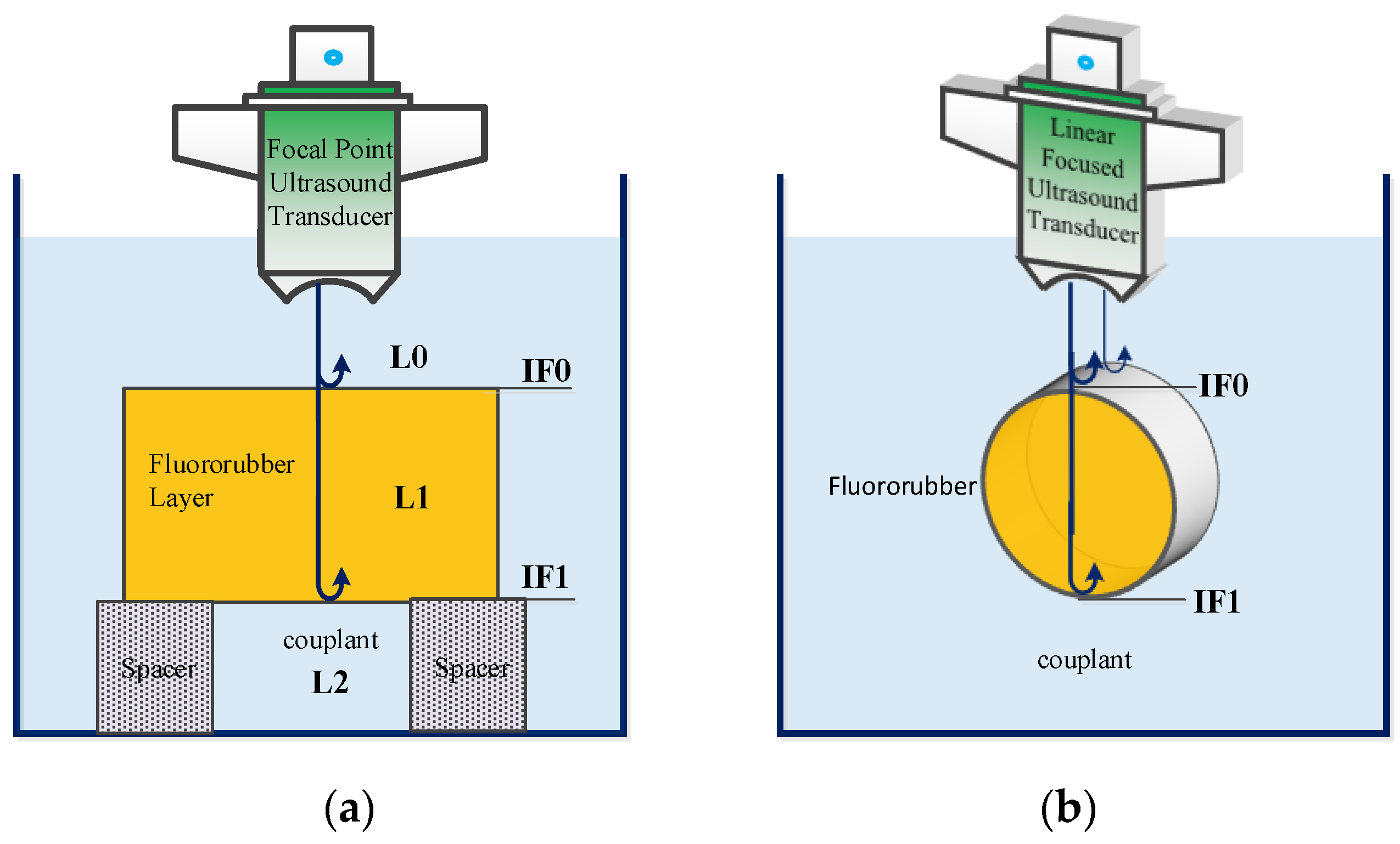
3.1. Ultrasound Measurement Setup

The structure of the ultrasonic evaluation system for the mechanical property degradation of fluororubber developed in this paper is shown in Figure 3. It consists of an ultrasonic sensor, an ultrasonic transmitter/receiver, a high-frequency signal analog-to-digital converter (ADC), a Z-axis motion platform and its controller as well as an industrial computer.
The ultrasonic sensor was mounted on the load surface of the Z-axis motion stage using a fixture. The ultrasonic transmitter/receiver (Model 5900PR, Olympus, Tokyo, Japan) has a transmit energy range adjustable from 1 μJ to 32 μJ, a gain range adjustable from 20 dB to 54 dB, and a bandwidth of 1 kHz to 200 MHz. The ADC (NDT-AD-82G-PCI, Acquisition Logic, Chantilly, VA, USA) has a sampling frequency of 4 GHz. The Z-axis motion stage uses a closed-loop motion control with linear motors and a grating scale, where the resolution of the grating scale is 50 nm. The Z-axis motion controller is equipped with a grating signal synchronization output interface, and the output encoding signal is connected to the ADC. The ADC generates an external trigger signal based on the step size of the grating signal and sends it to the ultrasonic transmitter/receiver to emit pulse excitation to the ultrasonic transducer. The ultrasonic transducer generates the ultrasonic signal and propagates it toward the specimen to be measured. The reflected echoes from the surface and internal structure of the specimen are received by the ultrasonic transducer, converted into electrical signals, and input into the ultrasonic transmitter/receiver. The signal conditioning circuit in the receiver amplifies and filters the signals, which are then sampled by the ADC.

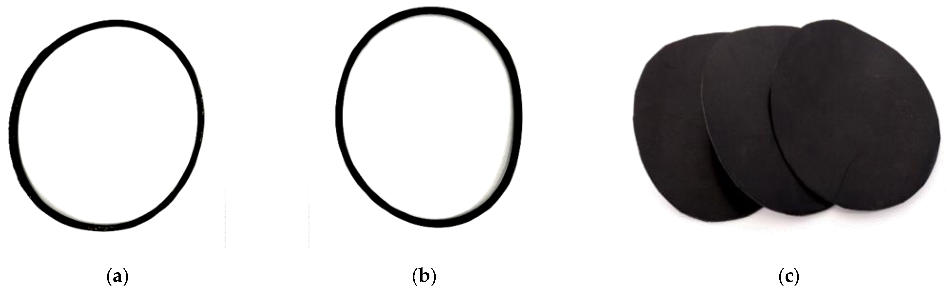
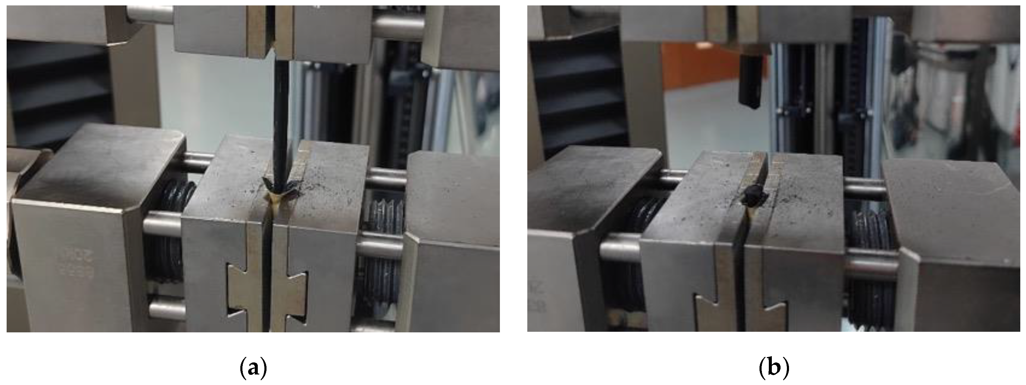
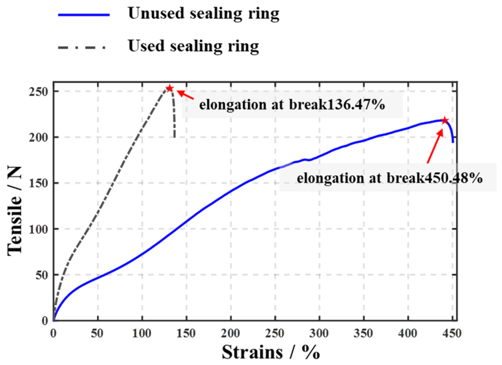
3.2. Preparation of Experimental and Reference Specimens

The experimental specimens included Φ166 × 6 fluororubber sealing rings used at a domestic nuclear power plant and externally purchased fluororubber gaskets. Among the rings, some had been in service for 1 year in nuclear power valve equipment, while the others were brand new, unused specimens (Figure 4).
According to previous studies, when the relationship between the acoustic impedance of the reference specimen and the test specimen satisfies 0.25 Z r e f / Z l 4 , the ultrasonic experimental system can achieve a good signal-to-noise ratio [8]. In this paper, epoxy resin (6040, Dow Corning Holding Company, Midland, MI, USA) was used to fabricate cylinders 6 mm in diameter and 5 mm in thickness with a density of 1090 kg/m. The longitudinal wave speed was 1960 m/s and the shear wave speed was 973 m/s. Figure 5a shows the physical image of the reference specimen, while Figure 5b presents the reflection coefficient values of the specimen at different angles in 20 °C water. From Figure 5, it can be observed that when the incident angle is within 10°, the acoustic reflection coefficient on the surface of the specimen approaches a fixed value, which meets the relevant requirements for measuring the two-dimensional reflection coefficient spectrum with a small-angle focused probe.

3.3. Experimental Design for Detection
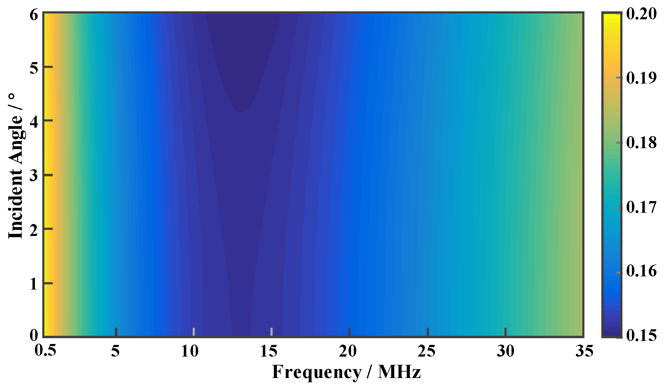
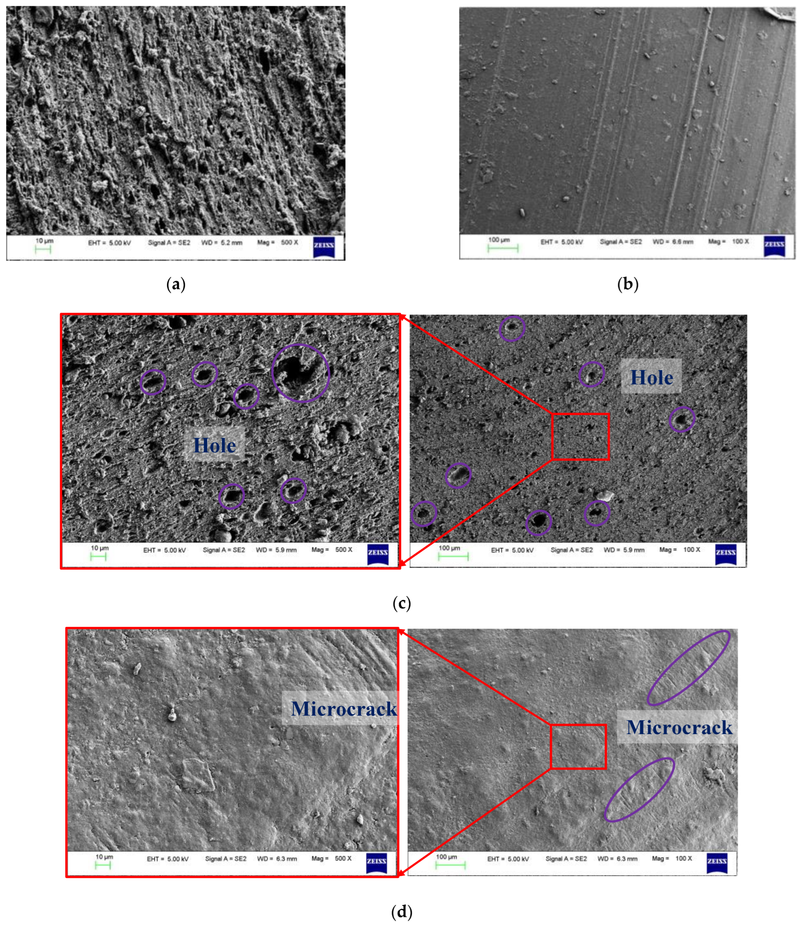
The sealing ring specimens, both in service and unused, were each cut into 40 mm segments. Five segments were used for the ultrasonic measurements, five segments for the mechanical tensile testing, and two segments for electron microscope analysis.
The steps for the ultrasonic measurement experiment of the sealing ring specimens were as follows. (1) Adjust the room temperature of the experimental space to 20 ± 1.5 °C, fix the ends of the cylindrical specimen of the truncated sealing ring to ensure that the bottom is more than 2 mm away from the bottom of the container. (2) Pour purified water into the container and make sure the temperature of the purified water is 20 ± 0.5 °C. (3) Observe the amplitude of the echo signal at the 0th interface, and adjust the spatial alignment between the line-focused ultrasonic transducer and the cylindrical specimen so that their axes are parallel and the upper surface of the specimen is located at the focal point of the transducer. (4) Move the line-focused ultrasonic transducer upward by 6.5 mm, and collect echo data every 0.1 mm from top to bottom until the transducer is 6.5 mm below the focal position, obtaining the V z , t data. (5) Repeat the steps to obtain the V r e f z , t data of reference specimen.
The above steps were repeated using a line-focused ultrasonic transducer (GE Alpha ISS, Buford, GA, USA) with excitation frequencies of 2.5 MHz and 25 MHz, respectively, to analyze the reflection coefficients in the ranges of 1 MHz~4 MHz and 15 MHz~35 MHz.
For the purchased fluororubber sealing gasket specimen, the aging test was conducted according to the relevant standards of the GB/T 3512 Test Methods for Accelerated Aging and Heat Resistance of Thermoplastic Rubber in Hot Air [27]. The test was performed at 70, 80, 90 and 100 °C (RH of 50%), and the testing time points were 1, 3, 6, 9 and 12 d, respectively.
After aging, the specimens were removed from the test chamber and placed in a room temperature environment at 20 ± 1.5 °C for 1 h before conducting the ultrasonic measurement experiments. Under the condition that the specimens were flatly clamped, the ultrasonic measurement steps of the fluororubber sealing gaskets specimens were not very different from those of the sealing ring specimens. The only difference was that a 25 MHz point-focused ultrasonic transducer (V324-N-SU, Olympus Corporation, Japan) was used.
Mechanical tensile tests were carried out on a universal material testing machine (Roell Z020, Zwick, Ulm, BW, Germany) with a tensile speed of 50 mm/min. To enhance the friction and prevent the specimen from slipping during the stretching process, sandpapers were wrapped around the gripping positions at both ends of the fluororubber specimen, ensuring that the tensile limit could be accurately measured. The specimen was clamped at the lower end, and the upper fixture was adjusted to a position vertically above the lower fixture, 20 mm apart. After resetting the load to zero, the upper fixture was tightened and the tensile test began. As shown in Figure 6, the upper fixture moved upward, while the load and strain data were recorded in real-time until the specimen broke.

4. Results

The reflection coefficient at the water–fluororubber interface was simulated using the viscoelastic and acoustic evaluation models presented in this study. The specific parameters used in the simulation are summarized in Table 1.
The simulation results are shown in Figure 7. It can be seen that the reflection coefficient of the water–fluororubber interface varied with both the angle and frequency. Within the small angle range, when the frequency was fixed, the reflection coefficient decreased as the angle increased, which was related to the conversion of some energy into shear waves. When the frequency changed, the reflection coefficient exhibited a minimum value. The frequency corresponding to this minimum value was related to the relaxation time τ.
As shown in Figure 8a, ultrasonic echo analysis of the fluororubber gasket specimen was conducted using a 2.5 MHz line-focus ultrasonic transducer. The main frequency of the echo signal shifted from 2.65 MHz in the IF0 interface echo to 2.45 MHz in the IF1 interface echo, with a noticeable frequency shift and attenuation phenomena.
The ultrasonic echo data acquisition and reflection coefficient spectrum calculation of the fluororubber sealing ring specimens were carried out using a line-focused ultrasonic transducer with a center frequency of 25 MHz and a −6 dB bandwidth from 18 MHz to 32 MHz. Before the experiment, the pulse reflection energy of the ultrasonic transmitter-receiver was adjusted to 32 µJ, and the amplification gain was set to 26 dB. As shown in Figure 9a, the echo signal waveform obtained from the IF0 interface clearly indicated that the echo amplitude of the used sealing ring specimen was significantly higher than that of the unused sealing ring specimen. The echo signal also exhibited a noticeable echo aliasing phenomenon.
Due to the higher attenuation coefficient of high-frequency ultrasound in fluororubber, the IF1 interface echo could not be effectively identified. Therefore, only the IF0 echo was used for the reflection coefficient fitting and solving. The parameters K s , H , ρ , k 1 , k 2 , η 0 , and η 1 were obtained by fitting the reflection coefficient curve at the normal incidence angle. In the process of fitting k 1 , k 2 , η 0 , and η 1 , the density value of the fluororubber, ρ , was first obtained experimentally, and then ρ was treated as a known quantity to construct the equations. The ultrasound reflection coefficient curves obtained from the measurements are shown as the star–dot curves in Figure 9c,d. The results based on the model fitting are represented by the solid red lines. The fitting results using multivariate nonlinear regression, based on the reflection coefficient spectrum, are expressed in terms of mean + variance, as shown in Table 2.
From the mechanical model fitting results, it can be observed that the elastic modulus of the used sealing ring was significantly higher than that of the unused sealing ring. As shown in Figure 10, the results of the mechanical tensile tests also confirmed the above conclusion. The tensile strength of the unused specimen was 12.24 ± 0.17 MPa, while the tensile strength of the used specimen was 35.65 ± 0.73 MPa. The elongation at break of the used specimen was only about 30% of that of the unused specimen. The thermal-oxidative aging tests of fluororubber in a hot-humid environment showed that the tensile strength of the material decreased from 12.24 MPa to 7.56 MPa, while the elongation at break decreased from 400% to 280%. The main mechanism behind this degradation was the rupture of crosslinking bonds and oxidative cleavage, which was not consistent with the results obtained from the used sealing ring specimens. The sealing rings involved in this paper were in service under high temperature and high oil conditions. The decrease in elongation at break observed during the oil-thermal aging test was more consistent with the actual situation [3,28]. This may have been due to the interaction between the oil medium molecules and the rubber, which accelerated the aging and degradation reactions of the rubber. Additionally, the diffusion and plasticizing effects of the oil medium led to an increase in the hardness of the sealing ring.
Using the fitting results from the acoustic model, specific values for the sound velocity and impedance were further obtained. It was found that the sound impedance of the used sealing ring was significantly higher than that of the unused sealing ring. In addition, the sound attenuation coefficient of the unused sealing ring was noticeably higher than that of the used sealing ring, which was positively correlated with the strain variable of the specimen. Due to the limited specimen size, the fitting results from the mechanical model alone did not support this conclusion. As shown in Figure 11a,c, the specimens’ cross-sections were observed using a field emission scanning electron microscope (FE-SEM), revealing that the cross-section of the unused specimen was rougher compared with the used specimen. The unused specimen showed more fibrous and coiled structures, indicating that the rubber underwent ductile fracture due to its good elasticity. On the other hand, the cross-section of the used specimen was flatter, which characterizes aging and hardening, suggesting changes in the crosslinking properties. Additionally, holes and pits, ranging from a few micrometers to tens of micrometers in diameter, were observed. These might be defects caused by rubber degradation and filler detachment, resulting in internal voids. Therefore, the acoustic attenuation in fluororubber is primarily caused by the scattering of long-chain macromolecules and the relaxation effects inherent to the elastomer itself. As a result, the ultrasonic attenuation in the unused sealing rings was higher than in the used sealing rings.
In the experiment, it was also observed that the ultrasonic reflection coefficient exhibited multiple peaks as the frequency changed, with the frequency difference between adjacent peaks approximately 3.4 MHz. This is a typical ultrasonic interference phenomenon in thin-layer media [29,30]. At the same time, from the waveform diagrams in Figure 8a and Figure 9a, a clear echo aliasing phenomenon was also observed. Both phenomena suggested that there were additional interfaces between the IF0 and IF1 interfaces. According to the manufacturing process of fluororubber, to enhance the sealing performance and durability of fluororubber sealing products, surface treatment processes such as coating were introduced during production. This step created a hardened layer on the surface of the fluororubber, generating a unique interface. The “multi-peak” phenomenon in the ultrasound reflection coefficient spectrum of the unused sealing ring was significantly stronger than that of the used sealing ring. This also indicates that after the surface hardened layer of the sealing ring eroded during service, the mechanical properties of the material degraded. As shown in Figure 11b,c, scanning electron microscopy (SEM) observations also revealed that the surface of the unused specimens was smoother than that of the used specimens. The surface of the used specimens exhibited numerous microcracks, approximately 1 to 2 microns wide and 100 microns long. The formation of these cracks may have been due to the attack of oil-based tertiary amines on the proton (H) in the —CH2CF2— group of the molecular chain, leading to a deprotonation process, followed by a dehydrofluorination reaction. This caused damage to the main chain structure of the sealing rings, resulting in performance degradation. Under the working temperature and pressure, further cracking occurred. This phenomenon also provided a microscopic explanation for the weakening of the ultrasonic interference in the hardened surface layer of the used sealing ring.

5. Conclusions and Discussion

In this paper, a second-order generalized Maxwell viscoelastic model was developed to characterize the behavior of fluororubber in small-strain conditions. This model was extended to high-frequency simple harmonic vibration, allowing for a detailed description of the relationship between mechanical properties and acoustic parameters. The model effectively explained the observed frequency shift and rapid attenuation phenomena that occurred during the propagation of ultrasonic waves through the fluororubber. These insights are crucial for understanding how material degradation in fluororubber affects its ultrasonic properties.
Building on this model, a nonlinear fitting-based ultrasonic nondestructive evaluation (NDE) method was proposed to assess the mechanical property degradation of fluororubber. The method was tested through a controlled experiment involving sealing rings used in nuclear power plants, comparing the mechanical properties of both the used and unused sealing rings. Mechanical tensile tests and electron microscopy analysis provided additional validation. The results showed a significant increase in the elastic modulus of the used sealing rings (2.97 ± 0.15 GPa) compared with the unused ones (2.75 ± 0.22 GPa), in line with the mechanical tensile test findings. Furthermore, the unused sealing rings exhibited a noticeably higher sound attenuation coefficient, corroborating the hypothesis that ultrasonic wave attenuation increases as the material degrades.
The proposed model and detection method offer a promising approach for evaluating the mechanical properties of fluororubber through ultrasonic techniques. The tensile strength and elastic modulus of fluororubber can be estimated using its elastic coefficients, while its compressibility can be inferred from the relaxation time and the acoustic attenuation coefficient. This provides a robust framework for the ultrasonic quantitative evaluation of fluororubber degradation. This methodology can be particularly useful in industries where material integrity and longevity are critical such as in nuclear power plants, aerospace, and automotive applications.
The investigation of ultrasonic attenuation and frequency shifts due to degradation in fluororubber is a significant contribution to ultrasonic nondestructive evaluation (NDE). Past research has explored similar phenomena in elastomers, but often without the detailed modeling of viscoelastic properties affecting ultrasonic wave propagation. The proposed model allows for a more precise understanding of how material degradation—manifested through changes in the elastic modulus and viscosity—affects ultrasonic wave velocity and attenuation. This advancement is crucial for improving the precision of ultrasonic NDE techniques, particularly in high-risk applications like nuclear power plants, where material failure can lead to severe consequences.
The decision to describe the stress–strain behavior of fluororubber using the generalized Hooke’s law, as opposed to more complex hyperelastic models, was based on the small-strain condition ( ε < 5 % ) encountered in this study. Hyperelastic models, such as Mooney–Rivlin, Yeoh, Ogden, and others, are typically employed for large strains ( ε > 30 % ), which are not relevant for ultrasonic wave propagation, where the strain amplitudes are small. At small strains, rubber-like materials behave linearly, and the stress–strain relationship is well-represented by Hooke’s law. This is consistent with the well-established understanding that the elastic response of rubber under small strains is essentially Hookean. Additionally, ultrasonic waves, being high-frequency vibrations, induce small deformations that are better captured by linear elasticity, making the use of complex, nonlinear hyperelastic models unnecessary. The random distribution of the long molecular chains in fluororubber leads to an isotropic material behavior, simplifying the stress–strain relationship and making the generalized Hooke’s law a more suitable model. The isotropic nature of fluororubber means that it behaves uniformly in all directions, eliminating the need for more complex models that account for the properties of directional materials.
Hooke’s law also offers computational simplicity, crucial for practical ultrasonic NDE applications. Although effective for small strains, future work should explore the transition to nonlinear behavior at larger strains or under extreme conditions like high temperatures or radiation. Additionally, refining the sensitivity and resolution of the method and developing simplified approaches will ensure the broader applicability of ultrasonic NDE for monitoring material degradation.

Author Contributions

Conceptualization, A.S. and B.J.; Methodology, L.W.; Validation, L.W.; Formal analysis, L.W.; Investigation, L.W. and L.Z.; Resources, T.W. and C.Z.; Data curation, L.Z.; Writing—original draft, L.W.; Writing—review & editing, L.Z.; Supervision, B.J.; Project administration, A.S.; Funding acquisition, A.S. All authors have read and agreed to the published version of the manuscript.

Funding

This research was funded by the National Natural Science Foundation of China grant number 52175521, the National Key R&D Program of China grant 2022YFB3403602, the Fundamental Research Funds for the Central Universities grant 226202400089 and Aviation Science Fund grant 2024Z006076001.

Data Availability Statement

The original contributions presented in this study are included in the article. Further inquiries can be directed to the corresponding author.

Conflicts of Interest

Authors Tong Wu and Chengliang Zhang were employed by the company China National Nuclear Corporation. The remaining authors declare that the research was conducted in the absence of any commercial or financial relationships that could be construed as a potential conflict of interest.

References

  1. Mello, C.C.; Costa, M.F. Fluororubber Aged Under Continuous Compression Set at Elevated Temperatures. In Volume 4: Materials Technology, Proceedings of the ASME 2015 34th International Conference on Ocean, Offshore and Arctic Engi-neering, St. John’s, NL, Canada, 31 May–5 June 2015; American Society of Mechanical Engineers: New York, NY, USA, 2015; p. V004T03A026. [Google Scholar] [CrossRef]
  2. Zhang, X.; Chang, X.; Chen, S.; Hua, M. Thermal Oxidation Aging Test and Life Assessment of Fluorine Rubber Sealing Materials. Equip. Environ. Eng. 2012, 9, 35–38. [Google Scholar]
  3. Zhang, L. Accelerated Aging Test and Life Prediction of Fluorine Rubber Under Long-Term Loading Conditions. Master’s Thesis, Beijing University of Chemical Technology, Beijing, China, 2024. [Google Scholar] [CrossRef]
  4. Korba, A.G.; Kumar, A.; Barkey, M. A hyper-elastic thermal aging constitutive model for rubber-like materials. J. Elastomers Plast. 2020, 52, 677–700. [Google Scholar] [CrossRef]
  5. Wang, Y.; Lin, Z.; Tang, T.; Song, L. Thermal damage detection of fluororubber material based on terahertz wave. Laser Optoelectron. Prog. 2020, 57, 297–302. [Google Scholar]
  6. Shaw, M.T.; MacKnight, W.J. Introduction to Polymer Viscoelasticity, 4th ed.; Wiley: Hoboken, NJ, USA, 2018. [Google Scholar]
  7. Shui, G.; Wang, Y.; Qu, J. Advances in nondestructive test and evaluation of material degradation using nonlinear ultrasound. Adv. Mech. 2005, 35, 52–68. [Google Scholar]
  8. Sun, A.; Bai, X.; Ju, B.-F. A new method for evaluating the degeneration of articular cartilage using pulse-echo ultrasound. Rev. Sci. Instrum. 2015, 86, 034301. [Google Scholar] [CrossRef]
  9. Zheng, L.; Wang, C.; Lu, J.; Sun, A. Application of the Reciprocity Theorem to Scattering of Surface Waves by a Surface Crack in Viscoelastic Material. Appl. Sci. 2022, 12, 10785. [Google Scholar] [CrossRef]
  10. Panwar, R.; Lee, J.R. Performance and Non-Destructive Evaluation Methods of Airborne Radome and Stealth Structures. Meas. Sci. Technol. 2018, 29, 062001. [Google Scholar]
  11. Castellano, A.; Foti, P.; Fraddosio, A.; Galietti, U.; Marzano, S.; Piccioni, M.D. Characterization of Material Damage by Ultrasonic Immersion Test. Procedia Eng. 2015, 109, 395–402. [Google Scholar]
  12. Castellano, A.; Mazzarisi, M.; Campanelli, S.L.; Angelastro, A.; Fraddosio, A.; Piccioni, M.D. Ultrasonic Characterization of Components Manufactured by Direct Laser Metal Deposition. Materials 2020, 13, 2658. [Google Scholar] [CrossRef]
  13. Jhang, K. Nonlinear Ultrasonic Techniques for Nondestructive Assessment of Micro Damage in Material: A Review. Int. J. Precis. Eng. Manuf. 2009, 10, 123–135. [Google Scholar]
  14. Chen, H.; Zhang, G.; Fan, D.; Fang, L.; Huang, L. Nonlinear Lamb Wave Analysis for Microdefect Identification in Mechanical Structural Health Assessment. Measurement 2020, 164, 108026. [Google Scholar] [CrossRef]
  15. Buck, O. Harmonic Generation for Measurement of Internal Stresses as Produced by Dislocations. IEEE Trans. Sonics Ultrason. 1976, 23, 346–350. [Google Scholar] [CrossRef]
  16. Koissin, V.; Demcenko, A.; Korneev, V.A. Isothermal Epoxy-Cure Monitoring Using Nonlinear Ultrasonics. Int. J. Adhes. Adhes. 2014, 52, 11–18. [Google Scholar] [CrossRef]
  17. Demcenko, A.; Koissin, V.; Korneev, V.A. Noncollinear Wave Mixing for Measurement of Dynamic Processes in Polymers: Physical Ageing in Thermoplastics and Epoxy Cure. Ultrasonics 2014, 54, 684–693. [Google Scholar] [CrossRef]
  18. Lai, Q.; Xu, C.; Wang, G.; Deng, M. Assessment of Aging Degradation in Rubber Using Quasi-Static Components of Ultrasonic Longitudinal Waves. J. Nondestruct. Eval. Diagn. Progn. Eng. Syst. 2024, 8, 021007. [Google Scholar] [CrossRef]
  19. Qiu, Y.; Wang, H.; Cheng, L.; Yang, L.; Liao, R. Non-destructive method by nonlinear ultrasonic measurements for aging characterization of silicone rubber. In Proceedings of the 2023 IEEE 6th International Electrical and Energy Conference (CIEEC), Hefei, China, 12–14 May 2023; pp. 3040–3044. [Google Scholar] [CrossRef]
  20. Zhang, S.; Zhuang, Z. Composite Materials and Viscoelastic Mechanics, 2nd ed.; China Machinal Press: Beijing, China, 2011. [Google Scholar]
  21. Rose, J.L.; Nagy, P.B. Ultrasonic Waves in Solid Media. J. Acoust. Soc. Am. 2000, 107, 1807–1808. [Google Scholar] [CrossRef]
  22. Du, G.; Zhu, Z.; Gong, X. Fundamentals of Acoustics, 3rd ed.; Nanjing University Press: Nanjing, China, 2012. [Google Scholar]
  23. Ding, H. Computational Ultrasound: Sound Field Analysis and Applications; Science Press: Beijing, China, 2010. [Google Scholar]
  24. Song, G.; Lu, D.; Lu, Y.; Liu, H.; Gao, Z.; Wu, B.; He, C. Velocity measurements of cylindrical surface waves with a large aperture line-focus acoustic transducer. Measurement 2016, 90, 103–109. [Google Scholar] [CrossRef]
  25. Chen, J.; Bai, X.; Yang, K.; Ju, B.-F. Angular measurement of acoustic reflection coefficients by the inversion of V(z, t) data with high frequency time-resolved acoustic microscopy. Rev. Sci. Instrum. 2012, 83, 014901. [Google Scholar] [CrossRef]
  26. Bai, X.; Sun, Z.; Sun, A.; Chen, J.; Ju, B.-F. Determination of the multiple local properties of thin layer with high lateral resolution by scanning acoustic microscopy. Rev. Sci. Instrum. 2014, 85, 094901. [Google Scholar] [CrossRef]
  27. GB/T 3512—2014; Test Methods for Accelerated Aging and Heat Resistance of Thermoplastic Rubber in Hot Air. China Standards Press: Beijing, China, 2014.
  28. Kader, M.A.; Bhowmick, A.K. Thermal ageing, degradation and swelling of acrylate rubber, fluororubber and their blends containing polyfunctional acrylates. Polym. Degrad. Stab. 2003, 79, 283–295. [Google Scholar] [CrossRef]
  29. Yang, X.; Verboven, E.; Ju, B.; Kersemans, M. Comparative study of ultrasonic techniques for reconstructing the multilayer structure of composites. NDT E Int. 2021, 121, 102460. [Google Scholar] [CrossRef]
  30. Brekhovskikh, L.M. Waves in Layered Media, 2nd ed.; Academic Press: New York, NY, USA, 2021. [Google Scholar]
Figure 1. Second-order generalized Maxwell viscoelastic model structure of fluororubber (a), and the step response curve of time to deformation (b).
Applsci 15 03903 g001
Figure 2. Ultrasonic layered propagation model in fluororubber experiment. (a) The model for fluororubber sheet specimen, and (b) the model for fluororubber column specimen. To ensure that the meas-urement area of the ring is straight, its axis must be aligned parallel to the axis of the linear focused transducer.
Applsci 15 03903 g002
Figure 3. Architecture of the ultrasonic evaluation system. This includes an ultrasonic sensor, an ultrasonic transmitter/receiver, a high-frequency signal analog-to-digital converter (ADC), a Z-axis motion platform, a motion platform controller, and an industrial computer.
Applsci 15 03903 g003
Figure 4. Fluororubber specimens for the ultrasonic measurement experiments. (a) The fluororubber sealing ring serviced for one year, (b) the brand new fluororubber sealing ring, and (c) fluororubber sealing gasket specimens purchased externally.
Applsci 15 03903 g004
Figure 5. (a) Reference specimen and (b) its theoretical reflection coefficient curve at different angles in 20 °C water. When the incident angle is within 10°, the acoustic reflection coefficient on the surface of the specimen approaches a fixed value.
Applsci 15 03903 g005
Figure 6. Spline stretching (a) and fracture (b).
Applsci 15 03903 g006
Figure 7. Simulation results of the reflection coefficient of the water–fluororubber interface. The reflection coefficient of the water–fluororubber interface varied with both the angle and frequency.
Applsci 15 03903 g007
Figure 8. Ultrasonic echo signals and their spectra conducted using a 2.5 MHz line-focus ultrasonic transducer. (a) Ultrasonic echo signals including the echo signals from IF0 and IF1. (b) The spectrum of echo signals from IF0 and IF1. The main frequency of the echo signal shifted from 2.65 MHz (IF0 interface echo) to 2.45 MHz (IF1 interface echo).
Applsci 15 03903 g008
Figure 9. Ultrasonic echo signals and reflection coefficient curve. (a) The ultrasonic echo signal amplitude from IF0 of the used sealing ring was higher than that of unused sealing ring. (b) In the spectrum of echo signals at the upper and lower interfaces, a noticeable echo aliasing phenomenon could be seen in the ultrasonic echo signal of the used sealing ring. (c) Model fitting curves and measured curve of the used sealing rings at the normal incidence angle. The values of the three curves were close, and their trends were similar. (d) Model fitting curves and the measured curve of the unused sealing rings at the normal incidence angle. The measured curve showed both increasing and decreasing fluctuations, but the overall trend followed that of the fitting curves, exhibiting a general increasing trend.
Applsci 15 03903 g009
Figure 10. Strain–load curves of the fluororubber sealing specimens. The elongation at break of the used sealing ring was 136.47%, much lower than that of the unused ring, which was 450.48%.
Applsci 15 03903 g010
Figure 11. The SEM images of the fluororubber specimens. (a) Cross-section of the used sealing ring, (b) cross-section of the unused sealing ring, (c) large number of holes in the cross-section of the used sealing ring, and (d) microcracks on the aged surface of the used sealing ring. Purple circles in panels (c) and (d) indicated holes and microcracks, respectively.
Applsci 15 03903 g011
Table 1. Simulation parameters of the reflection coefficient of the water–fluororubber interface.
ParametersValue
k 1 2.6 GPa
k 2 0.2 GPa
η 0 5 Pa·s
η 1 80 Pa·s
Density of water ρ 0 1000 kg/m3
Speed of sound in water c 0 1480 m/s
Table 2. The fitting results of the model parameters of the fluororubber sealing specimens.
Specimen TypeMechanical ModelAcoustic Model
Parameter NameFitted ValueParameter NameFitted Value
Used sealing ring k 1 2.20 ± 0.15 GPa K s 2.97 ± 0.15 GPa
k 2 1.42 ± 0.23 GPa H (2.22 ± 0.2) × 10−9
η 0 6.14 ± 0.35 Pa·s ρ 1380 ± 21 kg/m3
η 1 32.55 ± 1.26 Pa·s β (1.19 ± 0.57) × 10−5 s/rad·m
Unused sealing ring k 1 1.99 ± 0.08 GPa K s 2.75 ± 0.22 GPa
k 2 1.51 ± 0.15 GPa H (2.15 ± 0.18) × 10−9
η 0 6.63 ± 0.27 Pa·s ρ 1357 ± 16 kg/m3
η 1 25.23 ± 0.26 Pa·s β (2.37 ± 0.63) × 10−5 s/rad·m
Disclaimer/Publisher’s Note: The statements, opinions and data contained in all publications are solely those of the individual author(s) and contributor(s) and not of MDPI and/or the editor(s). MDPI and/or the editor(s) disclaim responsibility for any injury to people or property resulting from any ideas, methods, instructions or products referred to in the content.

