Article

A Numerical Study of the Sealing and Interstage Pressure Drop Characteristics of a Four-Tooth Three-Stage Brush Combination Seal

1
Institutes of Engineering Thermophysics, Chinese Academy of Sciences, Beijing 100190, China
2
National Key Laboratory of Science and Technology on Advanced Light-Duty Gas Turbine, Beijing 100190, China
3
School of Aeronautics and Astronautics, University of Chinese Academy of Sciences, Beijing 100049, China
4
Jinan Institute of Advanced Gas-Turbine, Jinan 251410, China
5
Beijing Key Laboratory of Distributed Combined Cooling Heating and Power System, Beijing 100190, China
*
Author to whom correspondence should be addressed.
Appl. Sci. 2025, 15(7), 3899; https://doi.org/10.3390/app15073899
Submission received: 27 January 2025 / Revised: 12 March 2025 / Accepted: 14 March 2025 / Published: 2 April 2025

Abstract

:

Featured Application

In this paper, the sealing mechanism and technical characteristics of the four-tooth three-stage brush combination seal are investigated, which is available for the Air-Turbo Rocket (ATR) engine for a new generation of aerospace vehicles.

Abstract

Premature seal failure induced by the unevenness of interstage pressure distribution in multi-stage brush seals significantly compromises the sealing efficiency of Air-Turbo Rocket (ATR) engines operating under high-pressure (megapascal-level) differential conditions. Conventional pressure equalization designs for such seals often result in significant leakage rate increases. This study addresses the pressure imbalance phenomenon in four-tooth three-stage brush composite seals through a novel fractal–geometric porous-media model, rigorously validated against experimental data. Systematic investigations were conducted to elucidate the effects of structural parameters and operational conditions on both sealing performance and pressure distribution characteristics. Key findings reveal that, under the prototype structure parameter, the first-, second-, and third-stage brush bundles account for 18.3%, 30.0%, and 43.3% of the total pressure drop, respectively, with grate teeth contributing 8.4%, demonstrating an inherent pressure imbalance. Axial brush spacing exhibits a minimal impact on the pressure distribution, while the gradient thickness settings of the brush bundles show limited influence. Radial clearance optimization and gradient backplate height adjustment effectively regulate pressure distribution, albeit with associated leakage rate increases. Structural modifications based on these principles achieved only a 5.8% leakage increment while reducing the maximum bundle pressure drop by 23%, demonstrating effective pressure balancing. A simplified analysis of entropy reveals that the fundamental mechanism governing the pressure imbalance stems from non-uniform entropy generation caused by aerodynamic damping dissipation across sequential brush stages. These findings establish a dampened dissipation-based theoretical framework for designing high-performance multistage brush seals in aerospace applications, providing critical insights for achieving an optimal balance between leakage control and pressure equalization in extreme-pressure environments.

1. Introduction

Reasonable technical improvements to aircraft engine seals can enhance the component efficiency of an engine and even increase the thrust-to-weight ratio of the entire aircraft [1]. Traditional labyrinth seals with grate teeth suffer from high leakage rates, frequent rotor–stator abrasion issues, and inadequate sealing performance and stability [2,3]. The leakage rate of brush seals is only 1/4 that of grate-tooth labyrinth seals, and the flexible brush bundle exhibits excellent tolerance to rotor vibrations, maintaining a stable low leakage [4,5,6]. While single-stage brush seals have a limited ability to withstand differential pressure, three-stage brush seals can endure differential pressures in the range of 0.6–1.0 MPa. However, three-stage brush seals face the issue of the unevenness of pressure drops between stages, which can lead to premature seal failure [7]. Therefore, researching the equilibrium characteristics and sealing performance of three-stage brush seals is of great significance for stabilizing and improving the sealing performance of aircraft engine seals under differential pressures of several megapascals.
Prior studies (e.g., Pugachev [8] or Wang [9]) established foundational models (porous media and tube bundles) to analyze interstage pressure imbalances and leakage flow distributions in multistage brush seals. Wen [10] and Qiu [11] further advanced numerical models (porous media and fluid–solid coupling) to quantify the effects of structural parameters (e.g., mounting angles or baffle height) on pressure drop equalization. Experimental studies by Raben [12] and Li [13] revealed trade-offs between sealing tightness, wear resistance, and temperature gradients in multi-stage brush seals under operating environments. Zhang [14] identified geometric parameters (axial/radial dimensions) and operational conditions (pressure ratio and rotational speed) as critical factors influencing leakage and thermal behavior in brush seals. Jiao [15] developed a transient fluid–solid coupling model to simulate brush wire dynamics and leakage under varying pressure differentials. Yan [16] generated 20 CFD-based training samples for a two-stage brush seal and trained a neural network to predict 50 sets of leakage and interstage imbalance data under varying brush wire displacements and protective clearances. The study analyzed the coupling effects of these parameters, revealing that brush wire row count impacts leakage inversely with protection clearance reduction. Li [17] developed a 3D multistage brush seal flow heat transfer model and validated it through numerical and experimental comparisons. The study analyzed how operational parameters affect interstage flow characteristics in both differentiated and uniform multistage brush seal configurations. The study revealed that configurations with an elevated backplane height exhibited the highest leakage, followed by those with a reduced brush bundle thickness. Zhao [18] based on the experimental data, modified the porous media model of a three-stage brush seal, and the leakage of the brush seal was accurately simulated by the numerical model through the dynamic adjustment of porosity, and the error of the calculated leakage compared with the experiment was less than 18.12%. Li [19] conducted a comparative analysis of flow field characteristics across multistage brush seal configurations, examining the impact of stage count on leakage behavior and flow dynamics. The study revealed that under constant pressure ratio conditions, incremental additions of stages (from first to third) progressively reduced both the pressure drop per stage on brush bundles and the flow field’s peak velocity. Furthermore, sealing efficiency exhibited a direct correlation with stage quantity under identical pressure ratios. Pan [20] conducted flow field analysis on two-stage brush seals, examining how pressure differential and second-stage backplane height impacts on leakage and pressure distribution. The results demonstrate that, in uniform two-stage configurations, the second-stage pressure drop percentage exceeded the first stage by approximately 20%, exhibiting significant distribution inhomogeneity.
Despite significant progress, existing studies lack a comprehensive framework that links sealing efficiency, interstage pressure imbalance, and entropy generation mechanisms in multistage brush seals. This paper establishes a numerical solution model of a four-tooth three-stage brush seal based on a numerical model of fractal geometry and porous media. Based on the verification and comparison of experimental data, the influence of the seal’s structural parameters and the sealing condition parameters on the pressure drop imbalance and sealing characteristics of three-stage brush seals is studied, the structural parameters of the combined seal are improved, and the mechanism of pressure drop imbalance of three-stage brush seals is elaborated from the viewpoint of entropy increase. The results of this paper provide a theoretical basis for the design of a three-stage brush seal structure.

2. Numerical Calculation Model of Four-Tooth Three-Stage Brush Seal

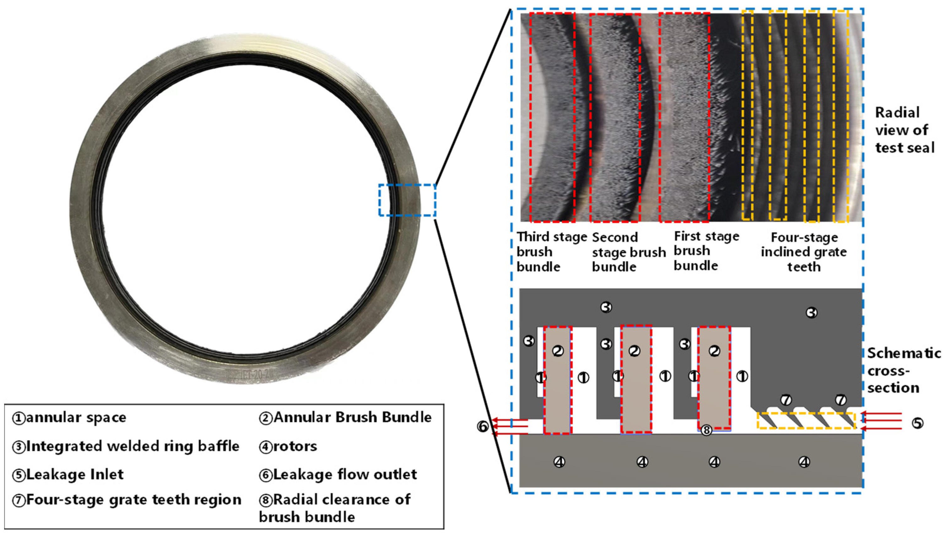
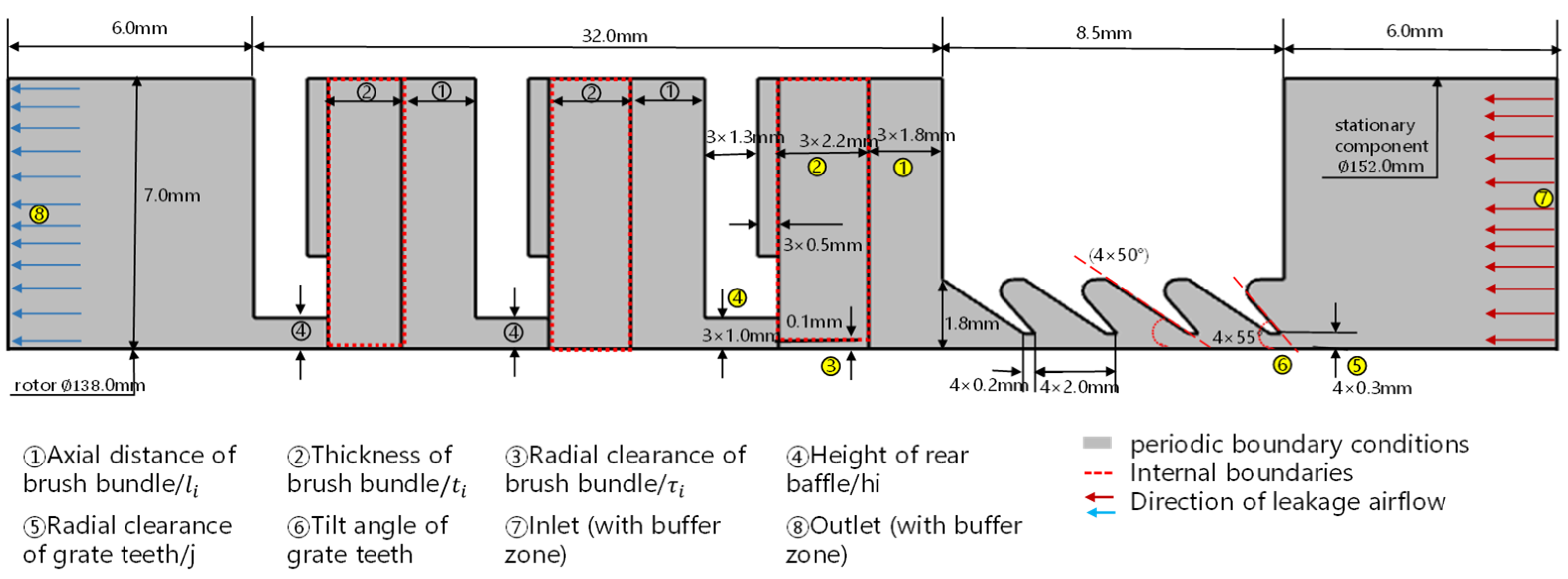
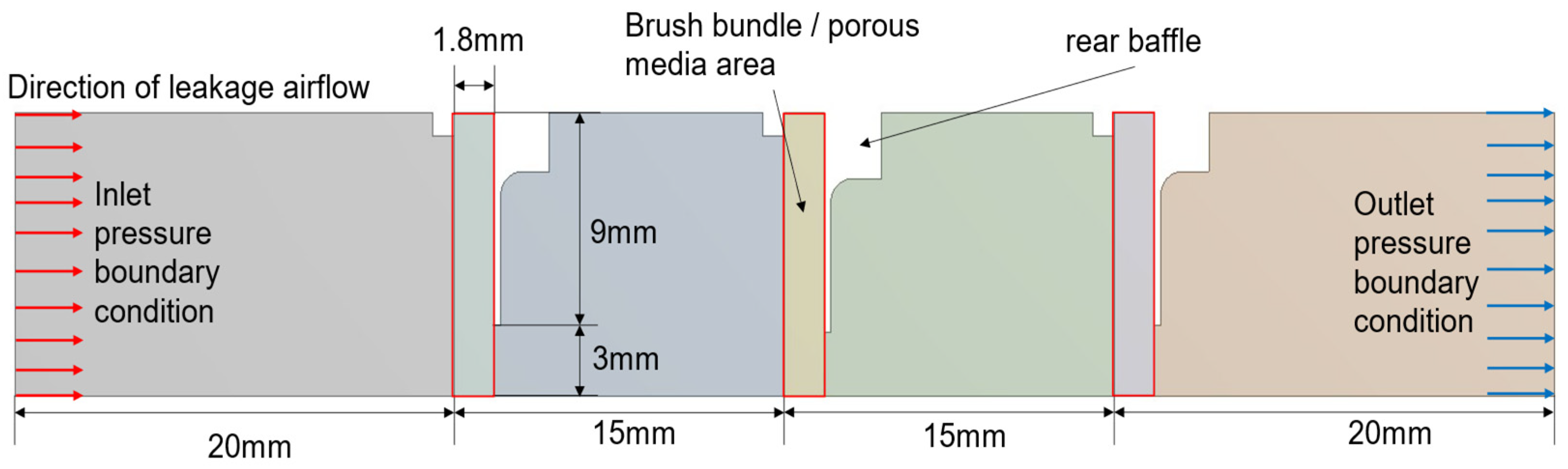
2.1. Geometric Structure and Calculation Domain

The brush seal consists of an annular high-pressure side baffle, a brush bundle, and a low-pressure side baffle welded to the outside. The brush bundle is formed by a fine high-temperature alloy filament tilted in a circumferential direction. The inner side of the brush bundle adheres to the rotor, and the high-pressure gas flows through the brush bundle to produce a pressure drop to achieve the seal. The brush bundle exhibits flexibility, allowing it to absorb the radial runout of the rotor and maintain stable sealing performance [21]. Multi-stage brush seals and grate–brush combination seals are gradually being designed and applied to aircraft engines to achieve sealing under megapascal differential pressure conditions. The four-tooth three-stage brush seal described in this paper adopts a one-piece manufacturing method, in which the three-stage brush seal and the four-stage beveled grate-tooth seal are axially combined and welded together, as shown in Figure 1. The seal has compact dimensions, a high pressure limit, and good sealing performance. Because the geometric model has asymmetry, the computational domain is selected as the arc segment region with a 1° circumferential direction, removing the solid region and the brush bundle welding region, and the cross-section schematic of the topological fluid domain is shown in Figure 2.
The structural parameters of the combined seal prototype (basic type) used in this paper are as follows: an inside diameter of 138.0 mm, an outside diameter of 158 mm, an axial thickness of 32.0 mm, a thickness of the brush bundle of 2.2 mm, an axial distance of the brush bundle of 1.8 mm, a height of the backplane of the brush bundle of 1.0 mm, an inclination angle of the grate teeth of 50.0°, a distance of the grate teeth of 2.0 mm, and a radial clearance at the top of the grate teeth of 0.3 mm. To investigate the influence of different structural parameters on the unevenness of the interstage pressure drop and sealing characteristics, the axial distance of the brush bundle, the thickness of the brush bundle, the radial clearance of the brush bundle, the height of the backplate, and the number of teeth, the radial clearance of the grate teeth, and the inclination angle of the grate teeth of the combined seal were modified; a series of sealing geometrical models with different structural parameters were composed; and the list of the specific parameters is shown in Table 1.

2.2. Numerical Modeling

The leakage flow analysis models for brush seal bristle packs mainly include the equivalent thickness model, the three-dimensional staggered tube bundle ideal-flow model, and the porous media model. Specifically, the semi-empirical nature of the equivalent thickness model and the low accuracy of the staggered tube bundle model limit their applicability. This study adopts the porous media framework for bristle pack simulations but replaces conventional non-Darcian models with a fractal geometry porous media model.

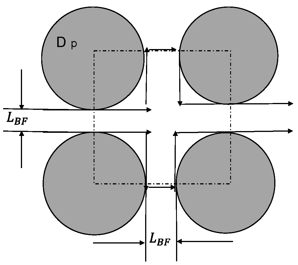
2.2.1. Fractal Geometry Porous Media Model

(1)
Theory of fractal geometry porous media model
The interstitial spaces within brush seal bristle packs are intricate and microscale. The structural similarity between porous media and bristle packs has led to the widespread use of porous media models for simulating leakage flow in brush seals. However, the capillary diameter, tortuosity, and surface morphology of porous media pores exhibit inherent randomness and irregularity, making traditional theoretical methods inadequate for analyzing their seepage characteristics. Given the fractal nature of porous microstructures and pore size distributions [22,23,24], advancements in fractal geometry offer novel approaches to refine porous media models for brush seals (see Appendix A for details of the derivation).
In the fractal geometry porous media equations, the effect of complex pores on the fluid is divided into viscous damped dissipation and inertial damped dissipation (see the Appendix A for details of the derivation).
Viscous Damping Dissipation control equation is:
p 1 l = 32 μ L 1 D T 3 + D T D f 2 D f 1 v s λ m a x * 1 + D T
where vs is the seepage velocity, m/s; μ is the viscous coefficient of the fluid, Pa∙s. Equation (1) (Equation (A25) in Appendix A) describes the pressure drop caused by viscous energy loss in porous media flow, i.e., viscous damping dissipation. Compared with the first term of the Ergun equation for porous media [4,5], this equation eliminates the empirical constant C and reveals the factors influencing viscous damping-induced losses, including fluid viscosity, pore size, the fractal dimension of capillary tortuosity, and the fractal dimension of the pores. Equation (1) also indicates that the pressure drop becomes zero when porosity ∅ = 1, while approaching infinity as porosity tends to zero, which aligns with the physical reality of brush bundles.
The inertial damping dissipation control equation is:
Δ p 2 l = ρ g h f = 3 2 + 1 β 4 5 2 β 2 ρ v s 2 2 2 1 l D T L 0 D T 1 λ ¯ 1 D T 2
where l is the length of the pore throat, in mm, and v s is the apparent velocity of the pore throat, in m/s. Equation (2) (Equation (A35) in Appendix A) represents the pressure loss caused by inertial damping dissipation. Compared with the second term of the Ergun equation [4,5], this equation eliminates empirical constants, assigns explicit physical meanings to each term, and demonstrates that the pressure drop is proportional to the square of velocity.
From Equations (1) and (2), the total pressure drop loss can be derived as the sum of viscous damping dissipation per unit length and inertial damping dissipation per unit length:
p 1 l + p 2 l = 32 μ L 1 D T 3 + D T D f 2 D f 1 v s λ m a x * 1 + D T + 3 2 + 1 β 4 5 2 β 2 ρ v s 2 2 2 1 l D T L 0 D T 1 λ ¯ 1 D T 2
(2)
Numerical modeling of multi-stage brush seals for fractal geometry porous media
The governing equations of the fractal geometry porous media model were derived in detail above, leading to the specific physical mechanisms of the viscous and inertial damping dissipation coefficients, and next, we will use the fractal geometry porous media in the numerical model of the brush seal.
Brush bundles consist of numerous fine filaments densely packed together. When airflow passes through the brush bundle, it undergoes significant density variations. Therefore, the gas flowing through both upstream and downstream regions is treated as an ideal compressible fluid:
p = ρ R T
where P denotes the gas pressure (Pa), ρ represents the gas density (kg/m3), R is the gas constant, and T indicates the temperature (K).
Given that the brush bundle region in brush seals exhibits anisotropic porous media flow characteristics, its RANS flow governing equations are:
ρ u i x i = 0
ρ u j u i x j = p x i + τ i j x j
where x i denotes the flow direction; Ui represents the velocity in the xi-direction (m/s); P indicates the gas pressure (Pa); τ i j is the stress tensor (N/m2), τ i j = μ e f f u i / x j + u j / x i 2 / 3 δ i j μ e f f u 1 / x 1 , μ e f f = μ + μ t ; and μ , μ t are molecular viscosity and turbulent viscosity (kg/(m-s)), respectively.
For fluid regions outside the brush bundle, turbulence modeling is required to establish additional Reynolds stresses for solving the RANS equations. This study employs the k-ω SST model.
Given the anisotropic structure of the brush bundle and the additional resistance induced by laminar flow within it, a fractal porous media model is adopted. This model specifically enhances the original formulation 39 for the brush bundle region, by incorporating non-Darcian high-speed seepage effects through the addition of viscous and inertial resistance terms derived from the fractal geometric porous media model:
F i = A i μ u i B i ρ u i u i
i.e.,
ρ u j u i x j = p x i + τ i j x j A i μ u i B i ρ u i u i
where
A i = a z 0 0 a n cos θ + a s sin θ B i = b z 0 0 b n cos θ + b s sin θ
where
a z = a n = 32 μ L 1 D T 3 + D T D f 2 D f 1 1 λ m a x * 1 + D T a s = 0.4 λ m i n λ m a x e d D f a n b z = b n = 3 2 + 1 β 4 5 2 β 2 ρ 2 2 1 l D T L 0 D T 1 λ ¯ 1 D T 2 b s = 0
where A i and B i denote the viscous resistance coefficient matrix and inertial resistance coefficient matrix within the brush bundle, respectively; a n , a z , a s represent the viscous resistance coefficients perpendicular to the circumferential, axial, and radial directions of the brush bundle; and b n , b z , b s correspond to the inertial resistance coefficients in these directions. Combining the fractal geometric porous media model with the reference, the values of A i in the radial, axial, and circumferential directions are 8.0 × 10⁴, 1.6 × 10⁵, and 4.2 × 10⁵ (kg/(m3·s)), respectively, while the B i values are 6.0 × 10⁵, 1.0 × 10⁶, and 1.5 × 10⁶ kg/m4. The inlet boundary conditions are given as the total pressure and temperature according to the differential pressure of the modeled conditions, the outlet is given as the static pressure according to the experimentally measured atmospheric pressure, the circumferential sides are set up as periodic symmetric boundaries, and the rotor surface and other solid surfaces are set up as no-slip wall surfaces.

2.2.2. Computational Model Set up

This paper uses ANSYS-Fluent 20.2 (version is ANSYS-Fluent 2020 R2) to calculate the leakage flow characteristics of a four-tooth three-stage brush combination seal. The finite volume method is used to discretize the governing equations. The k ω   S S T turbulence model is used to simulate the fluid region outside the brush bundle, in which the convection term adopts the second-order windward format, and the diffusion term adopts the center-difference format; in the interior of the brush bundle, because of the low air velocity and relatively small Reynolds number, the laminar model is used to simulate the flow in the porous media region of the brush bundle, and the ideal air is used as the work mass. The viscous resistances dissipation coefficient Ai of the fractal geometry porous medium in the axial, radial, and circumferential three directions, respectively, to take the value of 8.0 × 10⁴, 1.6 × 10⁵ and 4.2 × 10⁵ (kg/(m3·s), inertial resistances dissipation coefficient Bi in the corresponding direction to take 6.0 × 10⁵, 1.0 × 10⁶, and 1.5 × 10⁶ (kg/m4). The inlet boundary conditions are given as the total pressure and temperature according to the differential pressure of the modeled conditions, the outlet is given as the static pressure according to the experimentally measured atmospheric pressure, the circumferential sides are set up as periodic symmetric boundaries, and the rotor surface and other solid surfaces are set up as no-slip wall surfaces.

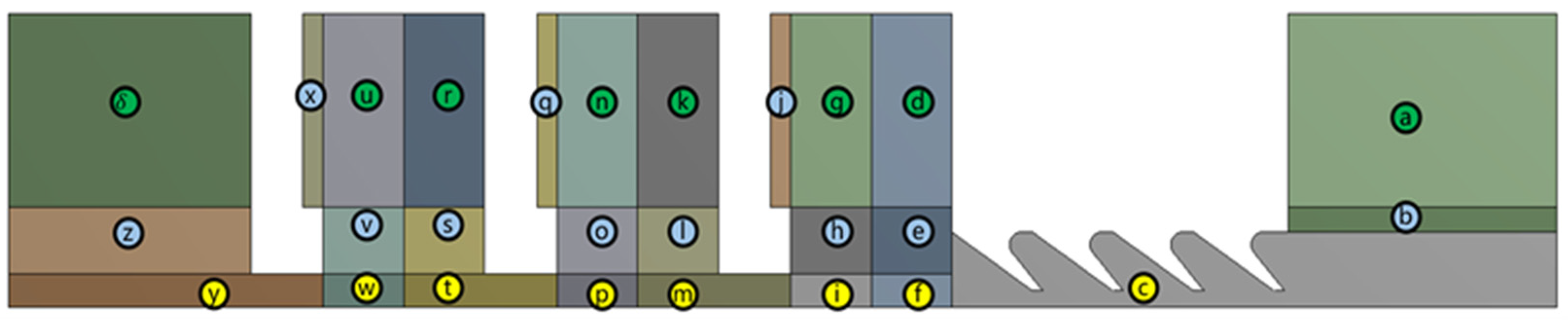
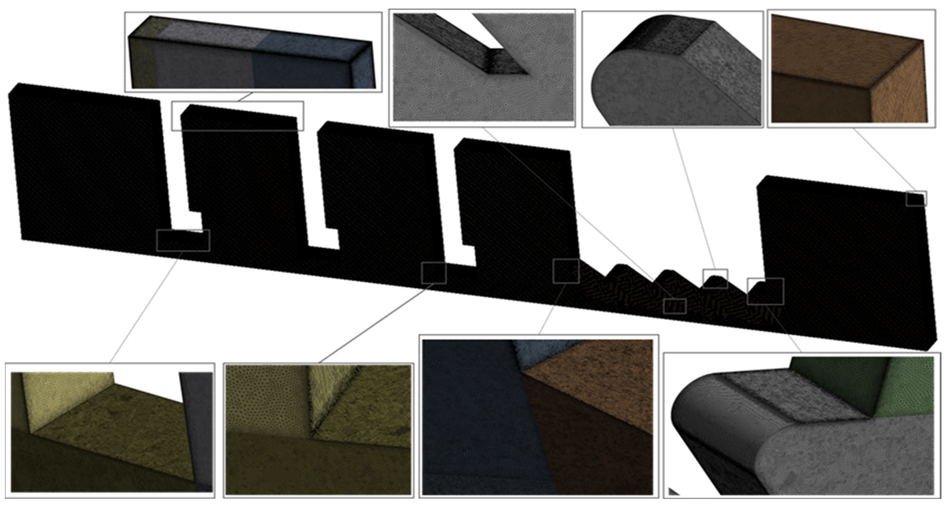
2.3. Mesh Generation

To take into account the calculation volume and the accuracy of the calculation, the calculation fluid domain adopts the structured mesh generation method, and the topological division of the calculation domain is shown in Figure 3. To improve the mesh quality, the top gap of the grate teeth, the top of the free end of the brush bundle, the bottom of the backplate, and the near-rotor region, such as the locations shown in Figure 3 c,f,i,m,p,t,w,y, use finer mesh sizes; the regions away from the rotor and the leakage channel, such as the locations shown in Figure 3 a,d,q,g,k,n,r,u,δ, are divided with coarser mesh sizes. Other regions, such as the positions shown in Figure 3 b,e,h,j,l,o,q,s,v,x,z, have mesh finenesses between the two. To ensure the calculation accuracy, the top of the grate teeth, the free end of the brush beam, the bottom of the backplate, and the near-rotor region, set up an encrypted mesh, so that the y+ value is less than 2, to meet the requirements of the turbulence model as shown in Figure 4.
For mesh independence, this paper verifies the mesh independence of the four-tooth three-stage brush combination seal porous media solution model, and Table 2 shows the comparison between the leakage rate of the seal test (81.62 g/s) and the calculated value at an inlet pressure of 0.6 MPa and a temperature of 25°. The calculation of the import and export flow accuracy as the basis for judging the grid is gradually refined and the number of grids increased; when the import and export flow is no longer with the change in the number of grids, this is considered to form stable calculation results. Calculations show that when the number of grids is greater than 6.83 × 10⁶, the import and export flow values no longer show significant changes; this paper selects the number of computational grids to be 6.95 × 10⁶.

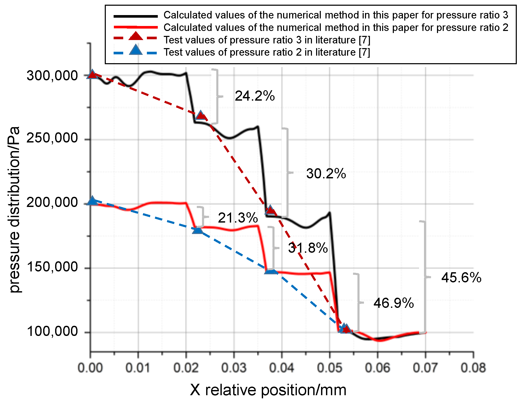
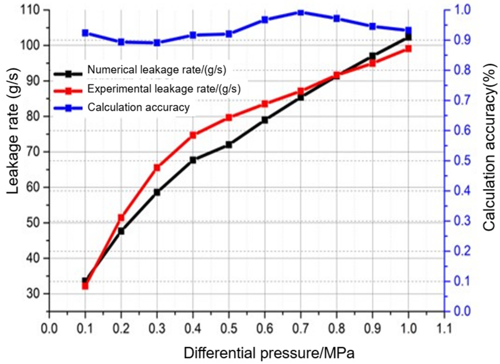
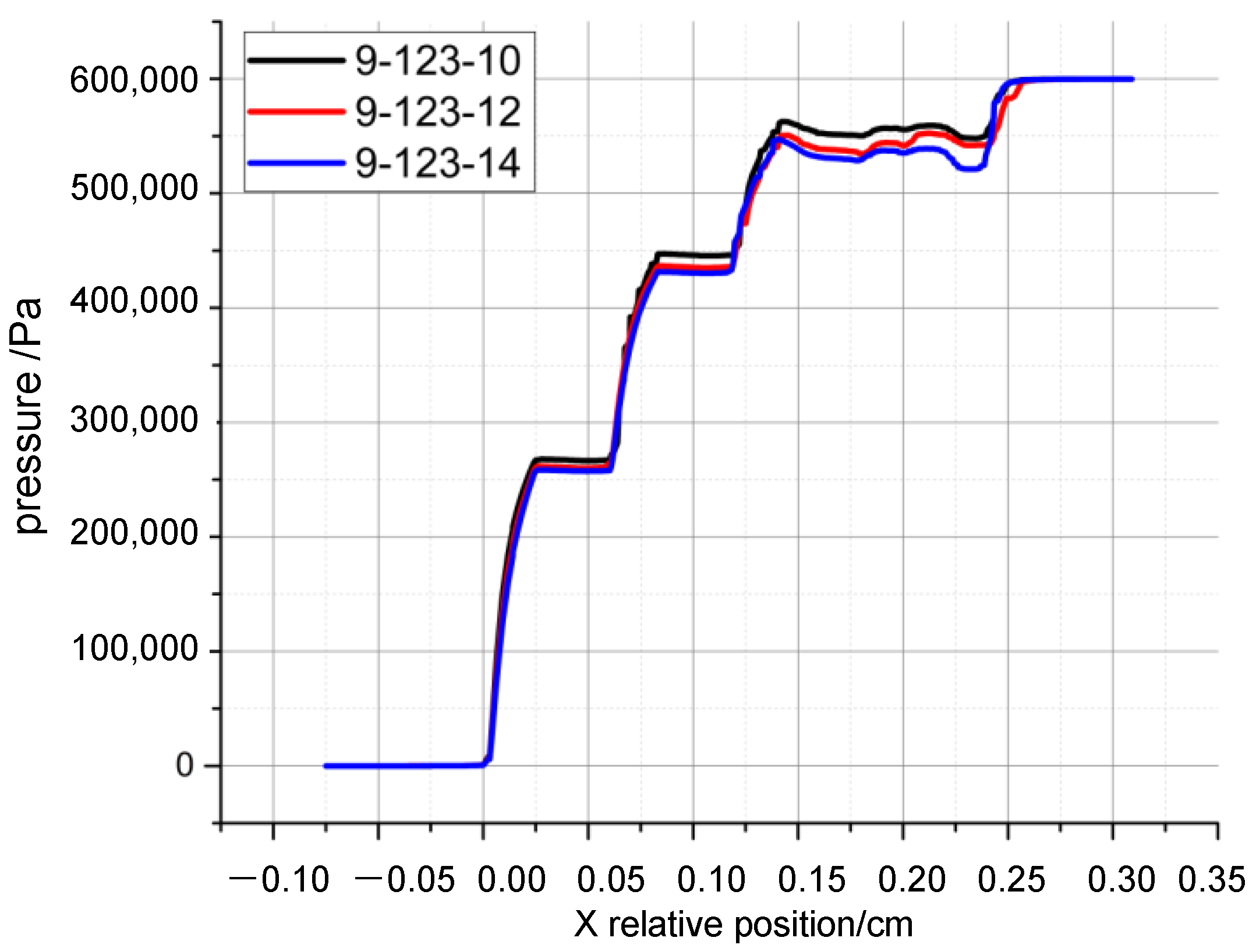
2.4. The Verification of the Accuracy of the Numerical Method

In this paper, based on the interstage pressure drop test data of multistage brush seals in the literature [7], the accuracy of the established numerical calculation method in solving the interstage pressure drop of multistage brush seals is verified. One study [7] has processed a three-stage brush seal test piece, constructed a multi-stage brush seal static experimental set up, measured the inter-stage pressure values of the three-stage brush seals at pressure ratios of 2.0 and 3.0, and pointed out that the experimental pressure ratios of the first-, second-, and third-stage brush bundles were 21–27%, 27–32%, and 41–52%. In this section, the study’s test piece geometry is modeled as shown in Figure 5, and the numerical calculation method of this paper is applied to calculate the interstage pressure drop distributions for pressure differences of 2.0 and 3.0 under the same operating conditions and boundary conditions.
As shown in Figure 6, the percentage of pressure drop of the first, second, and third brush bundles is 21.3%, 31.8%, and 46.9% at a pressure ratio of 2.0, and the percentage of pressure drop of the first, second, and third brush bundles is 24.2%, 30.2%, and 45.6% at a pressure ratio of 3.0, the interstage pressure drop has the characteristic of increasing by stages. The numerical calculation results are in good agreement with the test results, which ensures the credibility of the numerical calculation method developed in this paper for the calculation of the pressure drop of multi-stage brush seals.
To further verify the accuracy of the numerical calculation method established in this paper in terms of solving the sealing characteristics of multi-stage brush seals, this paper takes the four-tooth three-stage brush combination seal shown in Figure 2 as a test piece and carries out the three-stage brush seal differential pressure and leakage characteristics test (the test was completed in the high-temperature, high-speed sealing test bench of Shenyang University of Aeronautics and Astronautics). As shown in Figure 7, the test bench consists of an air supply system, power system, oil supply system, heating system, cooling system, and test system. The test bench has a rotational speed of 0–20,000 r/min, an inlet air temperature of 20–300 °C, a maximum test piece diameter of 630 mm, a maximum linear velocity of 500 m/s, and a maximum supply pressure of 1.0 MPa, which enables the measurement of the brush seal leakage flow rate under the working conditions of 250 °C and 1.0 MPa. The comparison of the leakage rate between the test data and the numerical calculation under different working condition parameters (differential pressure 0.1–1.0 MPa, 25 °C) is shown in Figure 8, and the error between the calculation results and the test results is ≤10%, which proves the accuracy of the numerical model of fractal geometries and porous media in the calculation of the sealing performance.

3. Analysis of Numerical Calculation Results

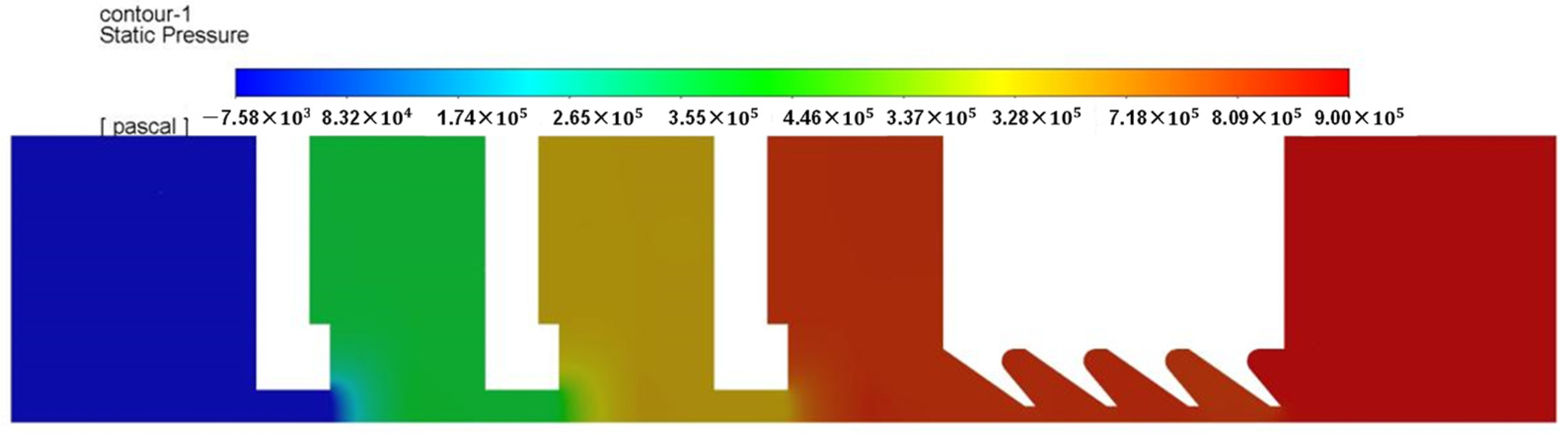
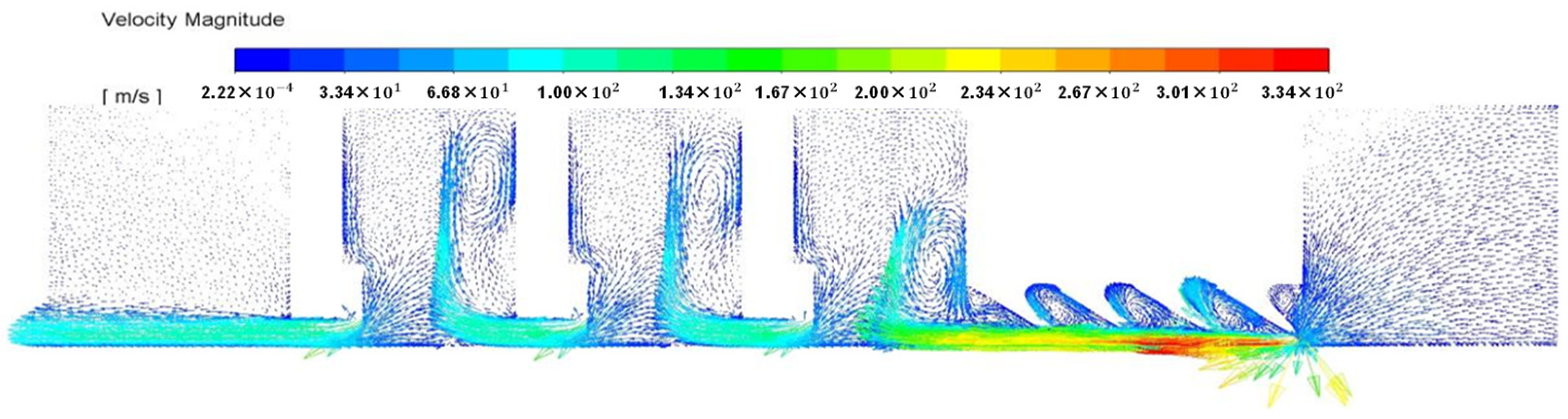
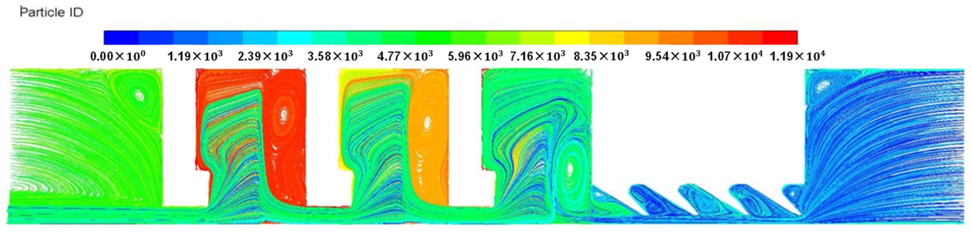
3.1. Sealing Mechanism and Pressure Drop Imbalance Characteristics of Four-Tooth Three-Stage Brush-Type Combined Seals

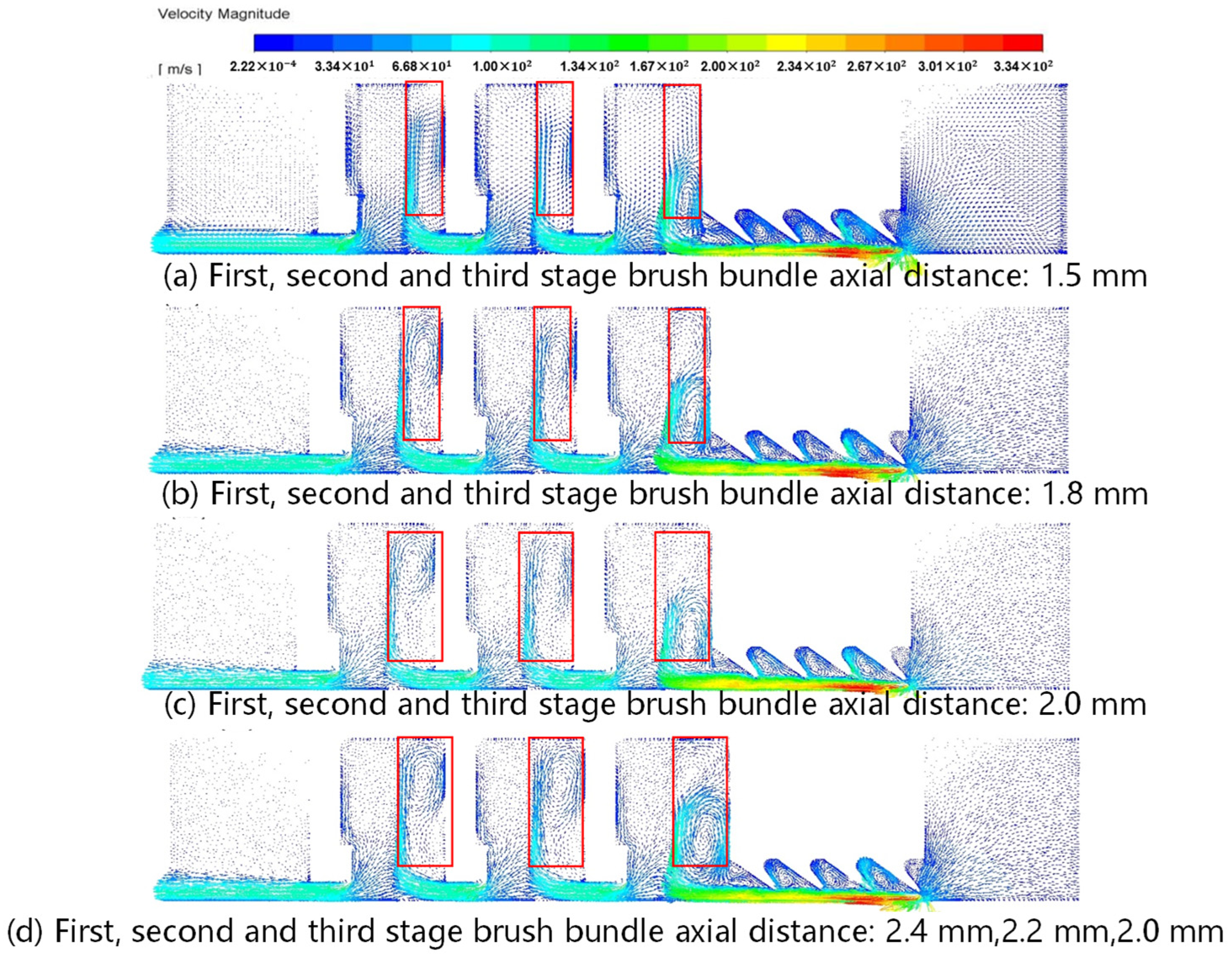
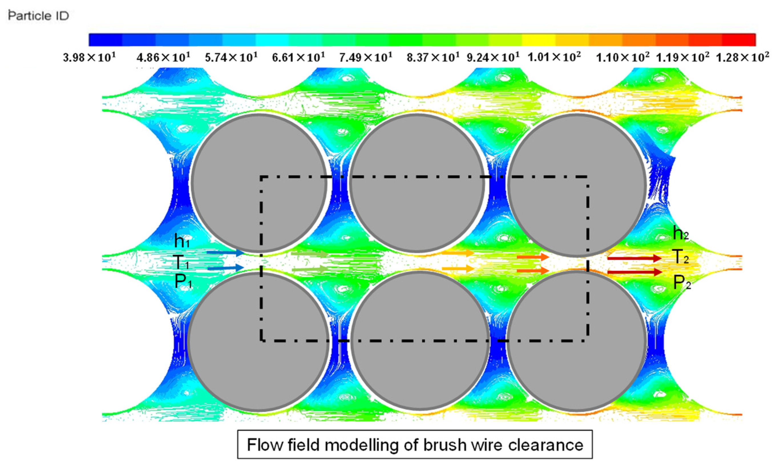
3.1.1. Seal Mechanism

In this subsection, numerical calculations are carried out for the four-tooth three-stage brush-type combination seal based on the fractal geometry porous media model. The calculation results show that, unlike other brush seals, in the four-tooth three-stage brush combination seal, the high-pressure leakage fluid flows through the four-stage grate teeth, and after the dissipation of the throttling effect at the top of the teeth and the vortex effect in the tooth cavities, it reduces part of the pressure and then flows through the brush bundles step by step. The pores between the brush filaments are fine and randomly distributed, further causing the irreversible dissipation of the high-speed fluid’s energy, and pressure reduction and sealing between the rotor and stator are realized under the accompanying small leakage flow.
As shown in Figure 9, the first tooth of the grate shows a sudden drop in pressure and maximum flow rate, which indicates that in the grate–brush combination seal, the first stage of the grate tooth throttling effect is obvious, can effectively prevent the impact of high-speed fluid on the downstream grate teeth and brush bundle. Figure 10 and Figure 11 show that there is a visible vortex effect in the grate tooth cavity area and in the buffer area in front of the brush bundles, which reduces some of the energy and pressure of the airflow. The brush bundle area is filled with pores, which are finely and randomly distributed and vary with the parameters of the seal structure and the sealing conditions. In these fine brush filament clearances, part of the kinetic energy of the high-energy gas is dissipated by the viscous friction of the attached surface layer, and the other part is separated into fine turbulence on the backwind side of the brush wire, which counteract each other’s dissipation. The effective dissipation of gas energy by the brush clearance makes the sealing performance of the brush bundle much better than that of the grate-tooth seal, which has a large clearance and relies on the tooth tip throttling effect and the tooth cavity vortex effect to achieve sealing. It should be noted that changes in the dimensions of the back baffle of the brush bundle can lead to marked changes in the leakage rate. This is due to the reduction in the height of the baffle, which results in a reduced cross-section of fluid flow and an increased flow velocity through the brush bundle, which enhances the separation, turbulence annihilation, and energy dissipation of the airflow behind the brush wires in the brush bundle, and ultimately leads to improved brush sealing performance. This is different to the reduction in the radial clearance of the grate tooth which enhances the throttling effect, resulting in a reduction in leakage.

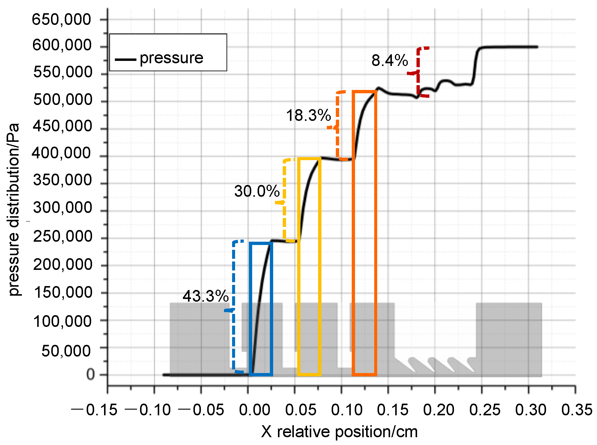
3.1.2. Uneven Pressure Drop Characteristics

The axial pressure distribution of the extracted four-tooth three-stage brush combination seal is shown in Figure 12. Like other multi-stage brush seals, the combination seal has a marked characteristic of uneven pressure drop between stages. From the upstream high pressure along the axial direction (X-negative direction) to the downstream low pressure, the pressure value in the area of the first grate tooth shows a significant decrease, and the grate teeth behind are also slightly decreased, with a total decrease of about 8.4%. Continuing along the X-negative direction to the area of the first-stage brush bundle, the pressure drop increases significantly, and the ratio of pressure drop for the first, second, and third-stage brush bundles is about 18.3%, 30.0%, and 43.3%, respectively. This shows a tendency for the pressure drop ratio to expand by stages, and there is an uneven characteristic of the pressure drop of the three-stage brush bundle.
In the process of high-pressure gas flowing through the three-stage brush seal, the pressure energy of the fluid is continuously converted into kinetic energy, and the gas flow rate increases quickly. As the gas flows through the brush beam, into the gap of the brush wire in the high-speed winding flow, the brush wire surface layer will produce viscous dissipation, and the back of the brush wire separation produces a large number of small-scale vortexes, which will produce an inertial dissipation of resistance. The two types of dissipation increase by stages, the entropy value of the gas also increases by stages, and the pressure drop increases rapidly with the increase in entropy value.

3.2. Seal Leakage Rate and Pressure Drop Distribution Change Rule Under Different Structural Parameters of Four-Tooth Three-Stage Brush-Type Combination Seal

To analyze the pressure drop unevenness and sealing characteristics of the four-tooth three-stage brush combination seal, different values of key parameters such as axial distance, thickness of brush bundle, radial clearance of brush bundle, height of backstop, as well as the inclination angle of grate teeth, the number of grate teeth, and the clearance at the top of the teeth were set up, the geometric model of the combination seal with different structural parameters was designed, and the changes in leakage rate and pressure drop distribution were calculated for the different models.
To simplify the graphical labeling, the models with different structural parameters are numbered in the following Figures in the form of ‘X-YYY-ZZ’ and ‘X-Z1-Z2-Z3’, where ‘X’ represents the structural parameter, specifically: ‘1-’ represents the ‘Axial distance’, ‘2-’ represents the brush bundle thickness, ‘7-’ represents the radial clearance of the brush bundle, and ‘9-’ represents the height of the baffle; where ‘YYY-ZZ’ means that the first, second, and third stages of the brush bundles are set with the same value of ZZ; and ‘Z1-Z2-Z3’ means that the first, second, and third stages of the brush bundles are set with different values of Z1, Z2, and Z3. For example, ‘1-123-15’ means that the axial distance of the first-, second-, and third-stage brush bundles are set to 1.5 mm, and ‘1-24-22-20’ means that the axial distance of the first-, second-, and third-stage brush bundles are set to 2.4 mm, 2.2 mm, 2.0 mm, respectively. Other structural parameters take similar markings.

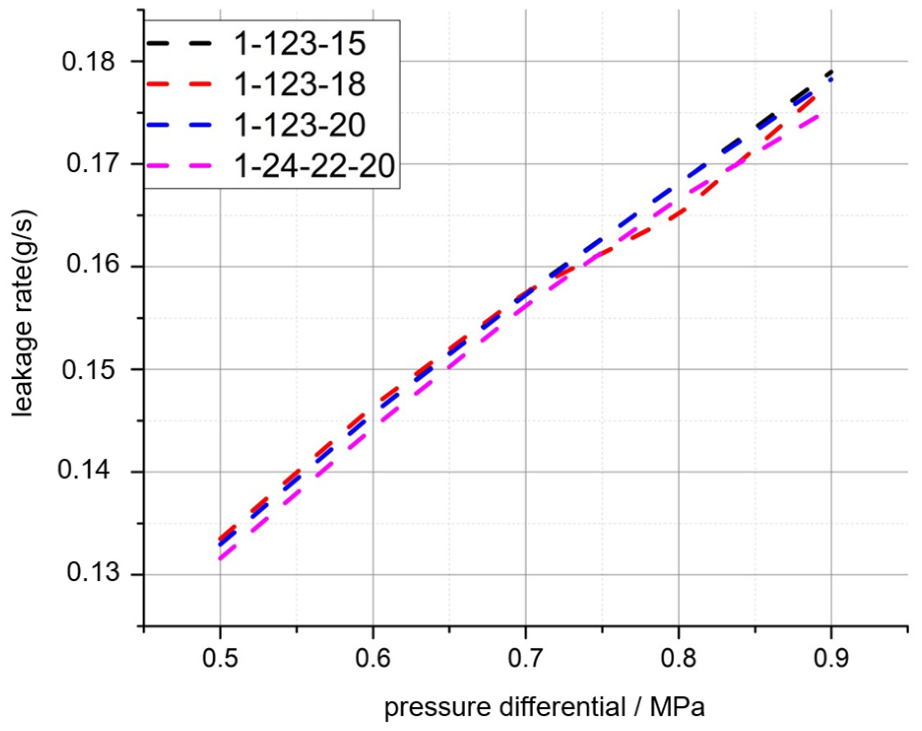
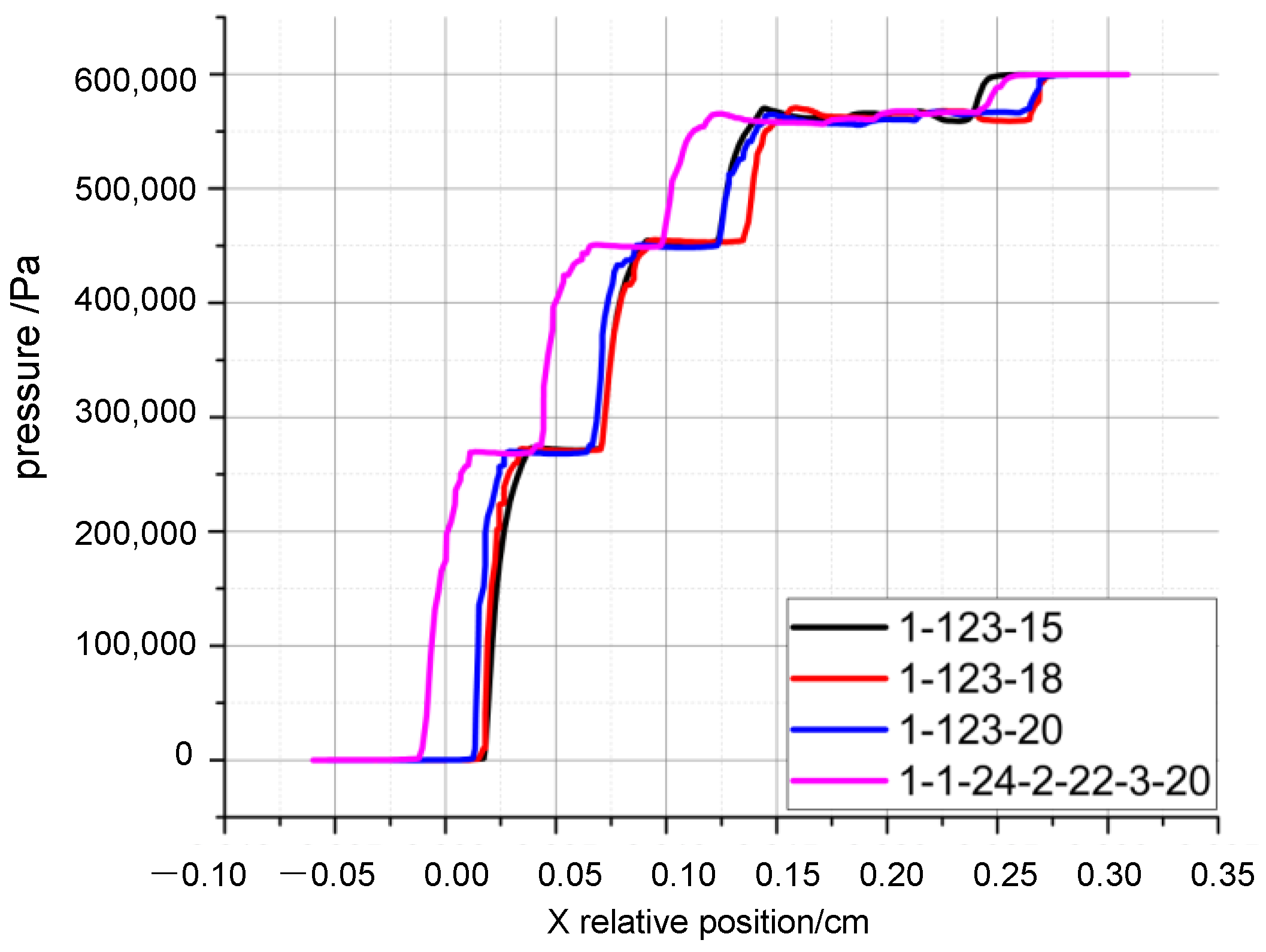
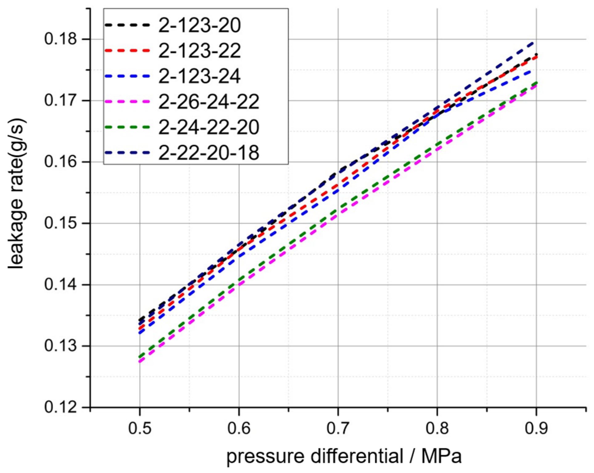
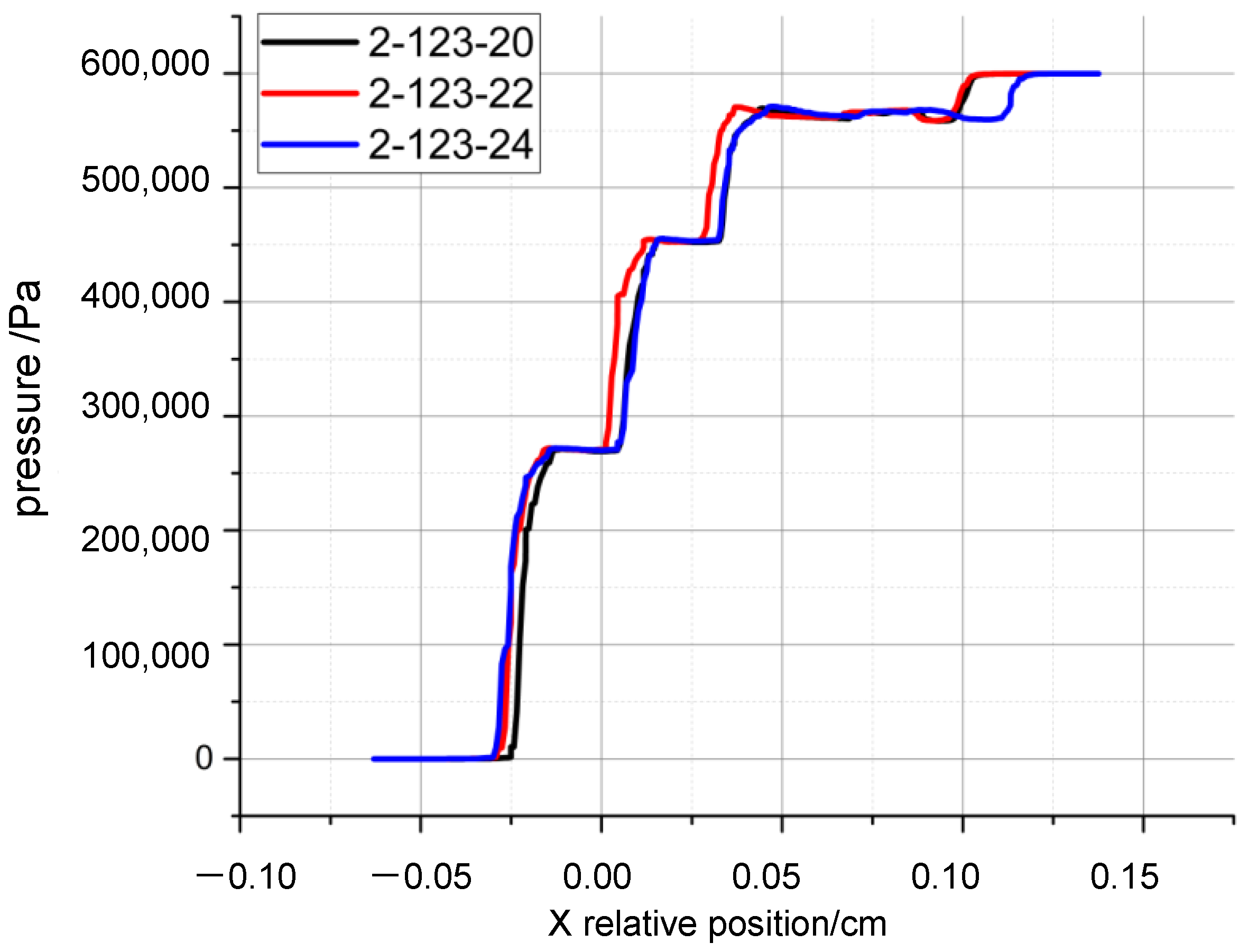
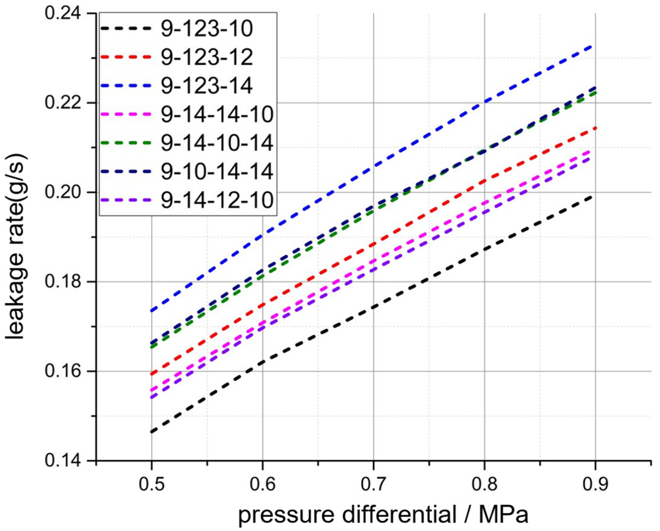
3.2.1. Axial Distance

Axial distance is an important structural parameter for multistage brush seals, which directly affects their compactness and overall weight. In this section, the effects of the axial distance in front of the first-, second-, and third-stage brush bundles on the leakage rate and pressure drop percentage of the seal are calculated, as shown in Figure 13, Figure 14 and Figure 15. The calculation results show that the axial distance of the multi-stage brush bundles has no significant effect on the leakage rate and the inter-stage pressure drop unevenness characteristics. As shown in Figure 13, with the increase in axial distance, the vortex effect in the axial gap is gradually strengthened, but the maximum flow velocity and leakage rate do not change much, which is because the vortex dissipation in the axial gap does not contribute a large proportion of the energy dissipation of the whole seal.

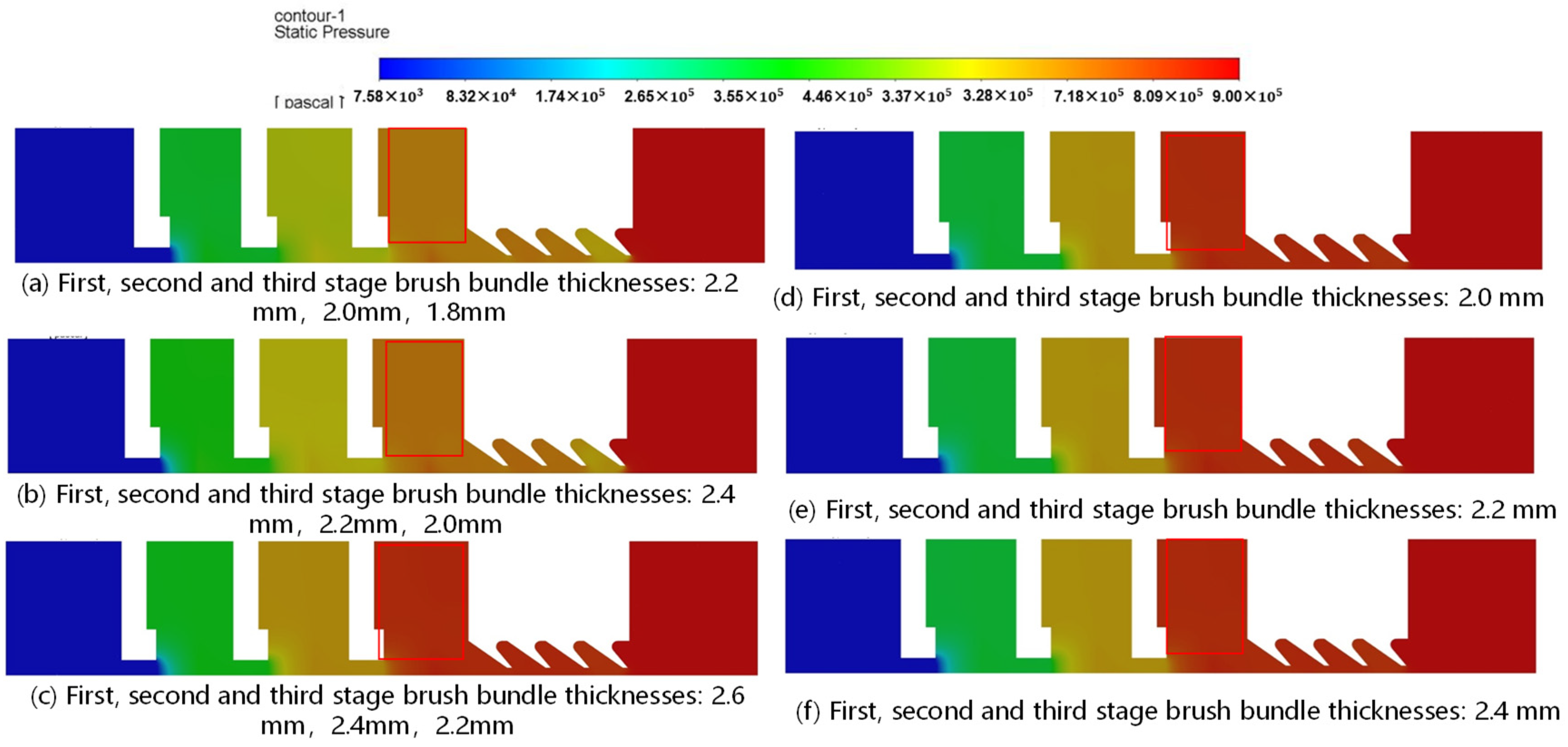
3.2.2. Thickness of Brush Bundle

Brush bundle thickness is one of the key structural parameters of multistage brush seals, which has a direct influence on the sealing performance and dimensional compactness of the brush bundle. As shown in Figure 16, the seal leakage rate decreases with the increase in the brush bundle thickness (including the total thickness). This is due to the increase in the thickness of the brush bundle, which leads to an increase in the dissipation generated by the resistance of the brush wire attachment layer inside the brush bundle and the dissipation generated by the inertial resistance of the brush wire clearance.
It can be seen that the change in the brush bundle thickness has some effect on the distribution of the interstage pressure drop percentage, as shown in Figure 17, Figure 18 and Figure 19. At the same time, the same setting of the thickness of the three levels of brush bundles does not noticeably affect the pressure drop percentage, as shown in Figure 18.
As the brush bundle thickness is increased, the leakage rate declines, although the change in pressure drop percentage is relatively minor. This is because the dissipation caused by the increase in brush bundle thickness is mainly the viscous dissipation of the attached layer on the surface of the brush wire, while the inertial damping dissipation remains relatively constant. As the thickness of the brush bundle increases, the downstream velocity declines, accompanied by a reduction in the inertial damping associated with the flow velocity. Consequently, the impact of adjusting the pressure drop percentage diminishes with the enhancement of the brush bundle thickness. This further indicates that the pressure drop unevenness characteristic is predominantly influenced by the inertial damping dissipation resulting from turbulence within the brush bundle.

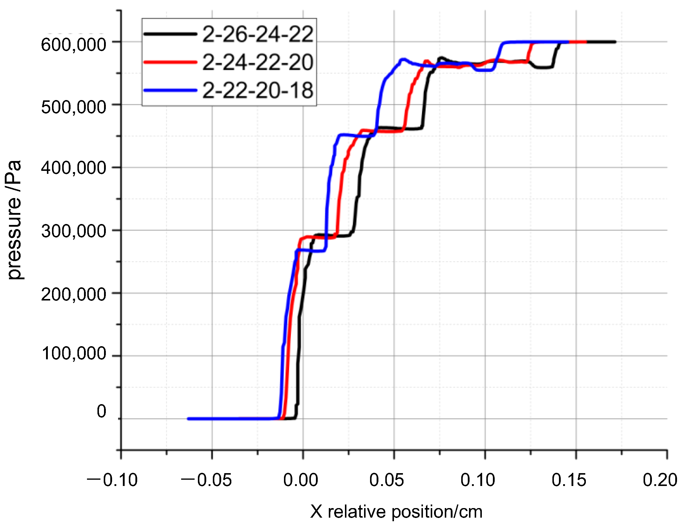
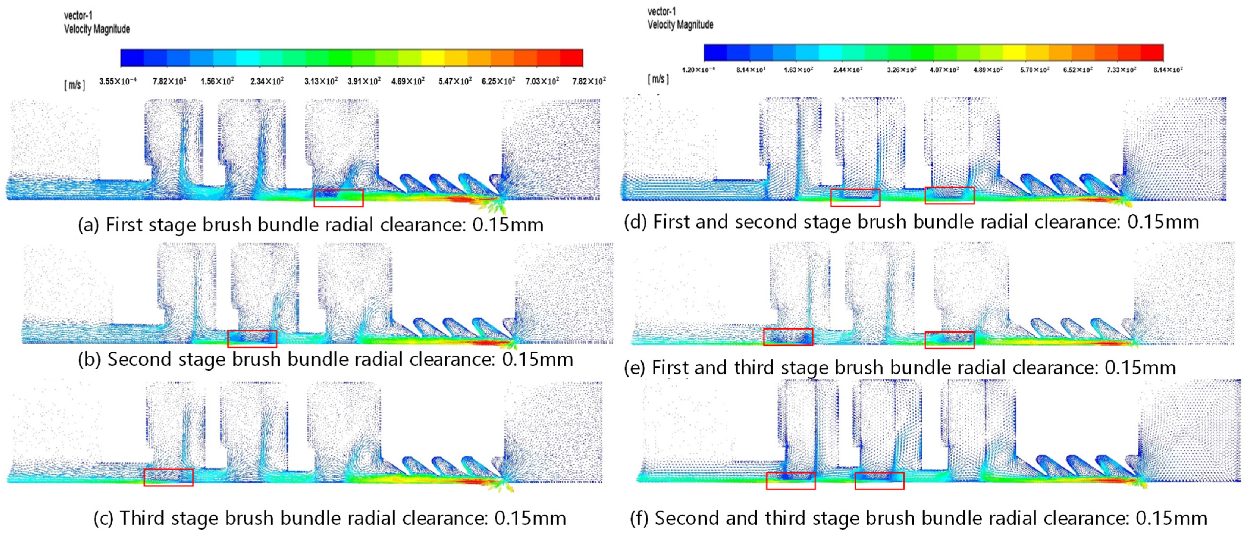
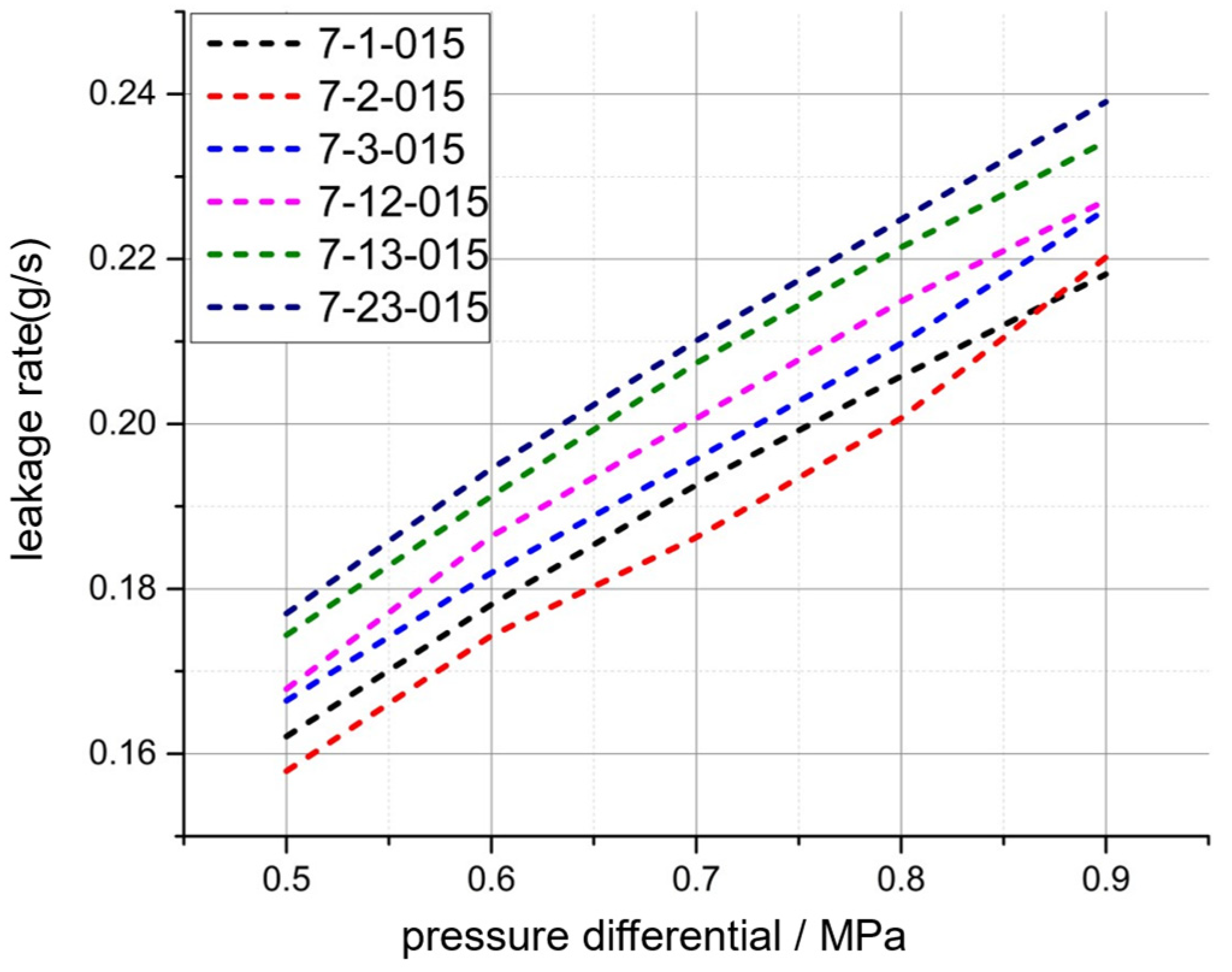
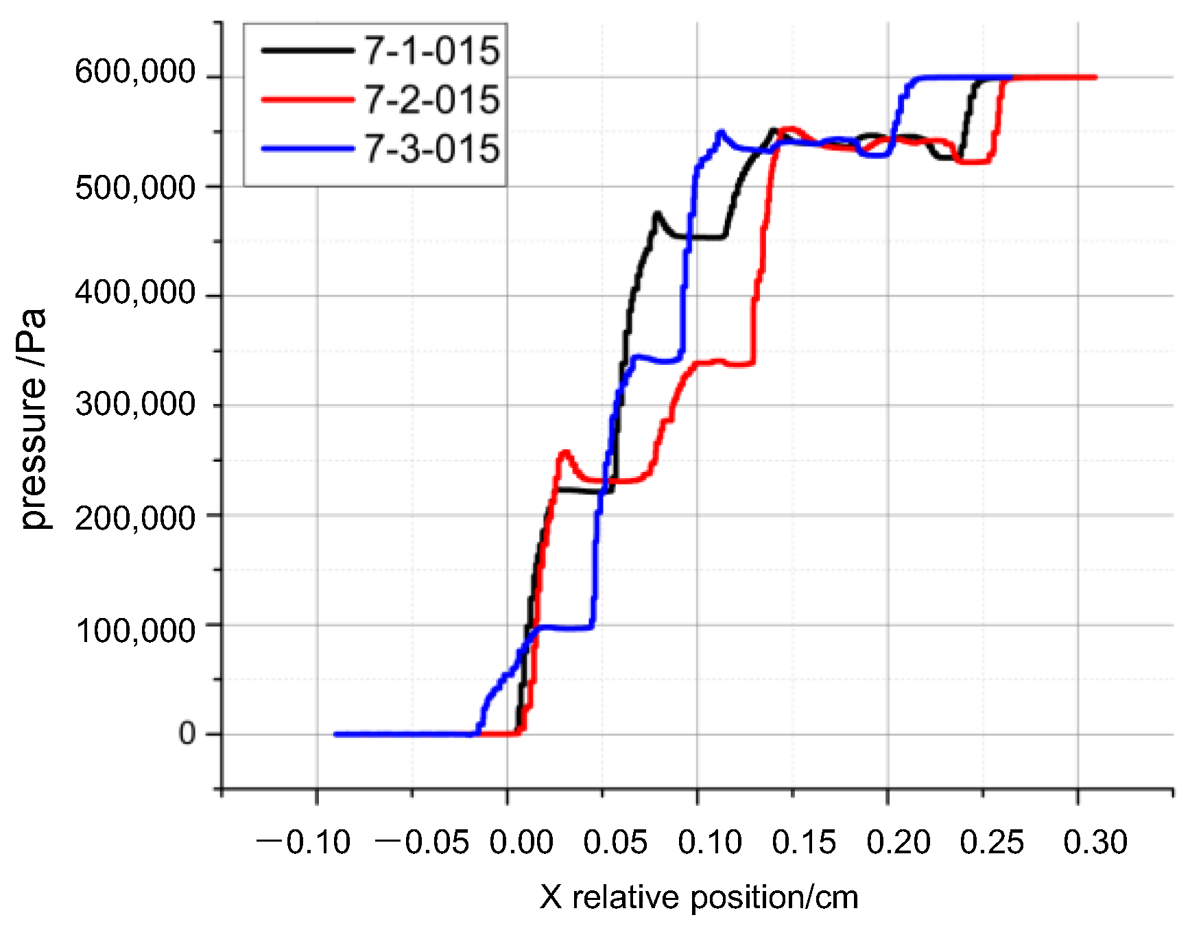
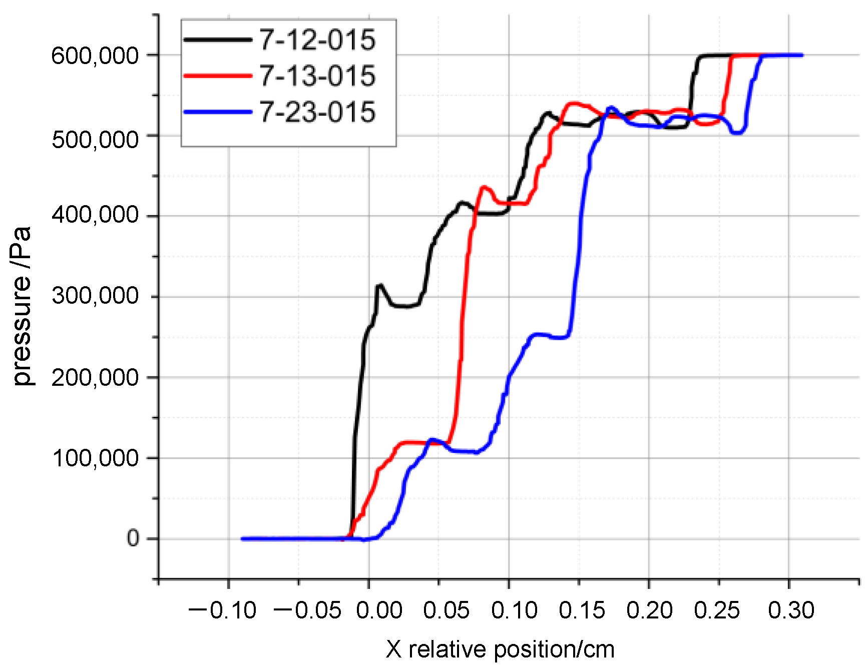
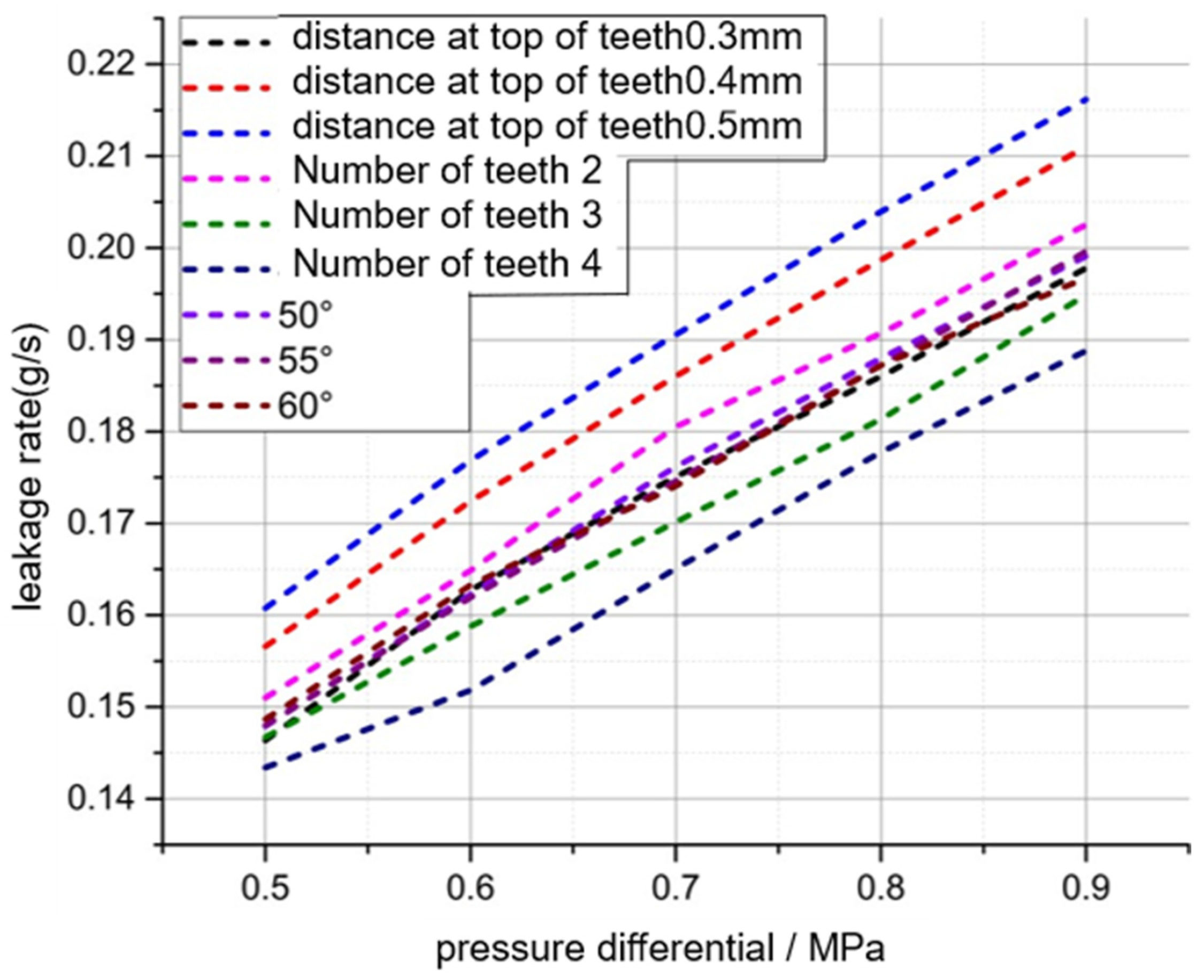
3.2.3. Radial Clearance

The radial clearance of seals in aircraft engines is one of the most sensitive parameters, and a reduction in this clearance is often directly related to an improvement in sealing performance. In the case of brush seals, the primary source of leakage is the “permeability effect” of brush bundle radial clearance. It is, therefore, necessary to investigate and analyze the influence of brush bundle radial clearance on the leakage rate and pressure drop percentage of the combined seal. The results of the calculations are presented in Figure 20 and Figure 21. As the radial clearance of the brush bundle increases, the clearance leakage rate and the leakage rate of the seal both increase. Notably, the leakage rate due to the radial clearance of the brush bundle is slightly lower in the first two stages than in the third stage. For a given radial clearance, the second stage exhibits a lower leakage rate than the first stage, which in turn exhibits a lower leakage rate than the third stage. The author posits that the second stage of the brush bundle dissipation ability is not inherently weaker than the first stage. Rather, the discrepancy can be attributed to the fact that the second-stage brush bundle has a similar thickness but a higher pressure drop percentage. Additionally, the second stage of the brush bundle clearance has the potential to alter the original flow field of the first and third stages. The “permeability effect” of the radial clearance of the second-stage brush bundle reduces the average pressure at the outlet of the first-stage brush bundle and increases the average velocity at the inlet of the third-stage brush bundle. This, in turn, increases the flow rate of the fluid in the first and third stages and improves the dissipation of inertial damping in the first and third stages. This is corroborated by the observed increase in the pressure drop percentage for the first and third stages in Figure 22, labeled ‘97-2-015’. It is evident that the alteration of the second stage brush bundle clearance not only results in the lowest leakage but also significantly enhances the uniformity of pressure drop between seal stages. About the highest leakage rate resulting from an increase in radial clearance in the third stage, can be attributed to the highest pressure drop percentage in the third stage and the highest leakage flow rate.
It is evident that the radial clearance of the brush bundle exerts a pronounced influence on the interstage pressure drop unevenness that is characteristic of the combined seal. Figure 22 and Figure 23 demonstrate that irrespective of whether the stage is single-stage or multi-stage, the setting of radial clearance markedly reduces the pressure drop percentage of the brush bundle within the stage. This is due to the ’permeability effect’ in the radial clearance, whereby a high-energy fluid leaks downstream rapidly through the clearance, thereby reducing the average velocity of the fluid flowing through the brush bundle region and weakening the dissipation effect of the brush bundle at the local stage. Two conclusions can be drawn from the calculations presented in this subsection. Firstly, the setting of the radial clearance of the brush bundle has a beneficial effect on the adjustment of the interstage pressure drop unevenness. Secondly, the adjustment of the interstage pressure drop percentage necessitates an increase in the leakage rate, with the second stage of the brush bundle clearance resulting in the lowest increment of the leakage rate.

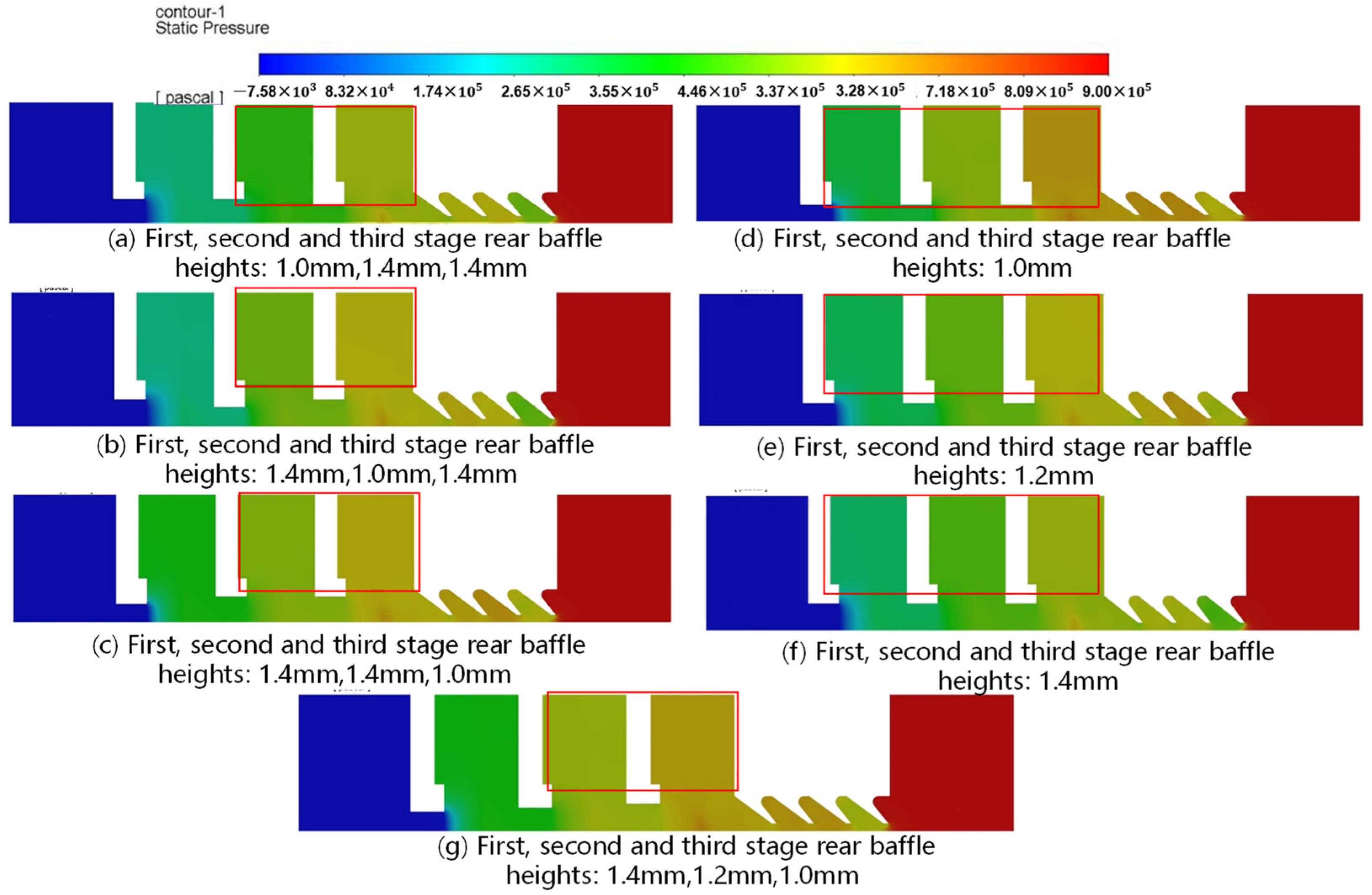
3.2.4. Height of Backplane Behind Brush Bundle

The height of the backplane is another key structural parameter of the brush seal, which often affects the leakage rate and pressure limitations of the brush bundle. As shown in Figure 24 and Figure 25, the height of the backplane of all stages of brush bundles increases gradually at the same time, the pressure drop percentage in the area of the brush bundle decreases, and the pressure drop percentage in the area of the grate teeth increases. With the increase in the baffle height, the pressure drop percentage of all stages of the brush bundle is unevenly increased slightly (the percentage of the first and second stage is slightly decreased). This is due to the higher baffle, and brush bundle flow area expansion, resulting in lower flow velocity in the brush bundle, the dissipation is weakened, and the leakage rate increases. At the same time, the area of the flow channel in the grate teeth area remains unchanged, the flow rate increases, the ‘throttle effect’ of the grate teeth is enhanced, and the dissipation of the grate teeth increases; therefore, the pressure drop percentage in the grate teeth area is increased.
As shown in Figure 26 and Figure 27, different settings of baffle heights, such as ‘9-14-14-10’, result in a significant increase in the pressure drop percentage of the brush bundle stage with a small value of baffle height. This shows that the baffle height is effective for the adjustment of pressure drop unevenness characteristics between multi-stage brush seal stages. By reducing the baffle height, the leakage fluid flow cross-section narrows, the flow velocity increases, the irreversible dissipation due to inertial damping in the brush bundle increases, and the pressure drop percentage of the brush bundle at that stage is increased, which is compared to the pressure drop percentage of the brush bundle at ‘9-123-14’, ‘9-14-10-14’, ‘9-10-14-14’, ‘9-14-14-10’, and ’9-14-12-10’ in Figure 26.
Figure 27 shows the effect of the height of the backplane of the brush bundle on the leakage rate of the combined seal, from which it can be seen that the reduction in the height of the backplane can significantly reduce the leakage rate of the brush seal and improve the sealing performance of the combined seal. It should be emphasized that the change in the baffle parameter has a limited effect on the viscous damping dissipation in the brush bundle because the leakage pore size in the brush bundle is not extended and the number of pores is not increased. The increase in the brush bundle pressure drop percentage caused by the decrease in baffle height is due to the increase in the annihilation of a large amount of high-frequency, small-scale turbulences in the brush bundle pores, i.e., the increase in the inertial damping dissipation. With the reduction in the baffle height, the narrower flow channel increases the flow velocity, and the inertial damping dissipation is aggravated; this is the main reason for the effect of the baffle dimensions on the leakage rate of the brush bundle, and it should be noticed that this is differentiated from the “throttle effect” at the top of the teeth of the grate teeth. It should also be noted that a change in the baffle size unrelated to the area of the brush bundle does not have the same effect of reducing the leakage value.

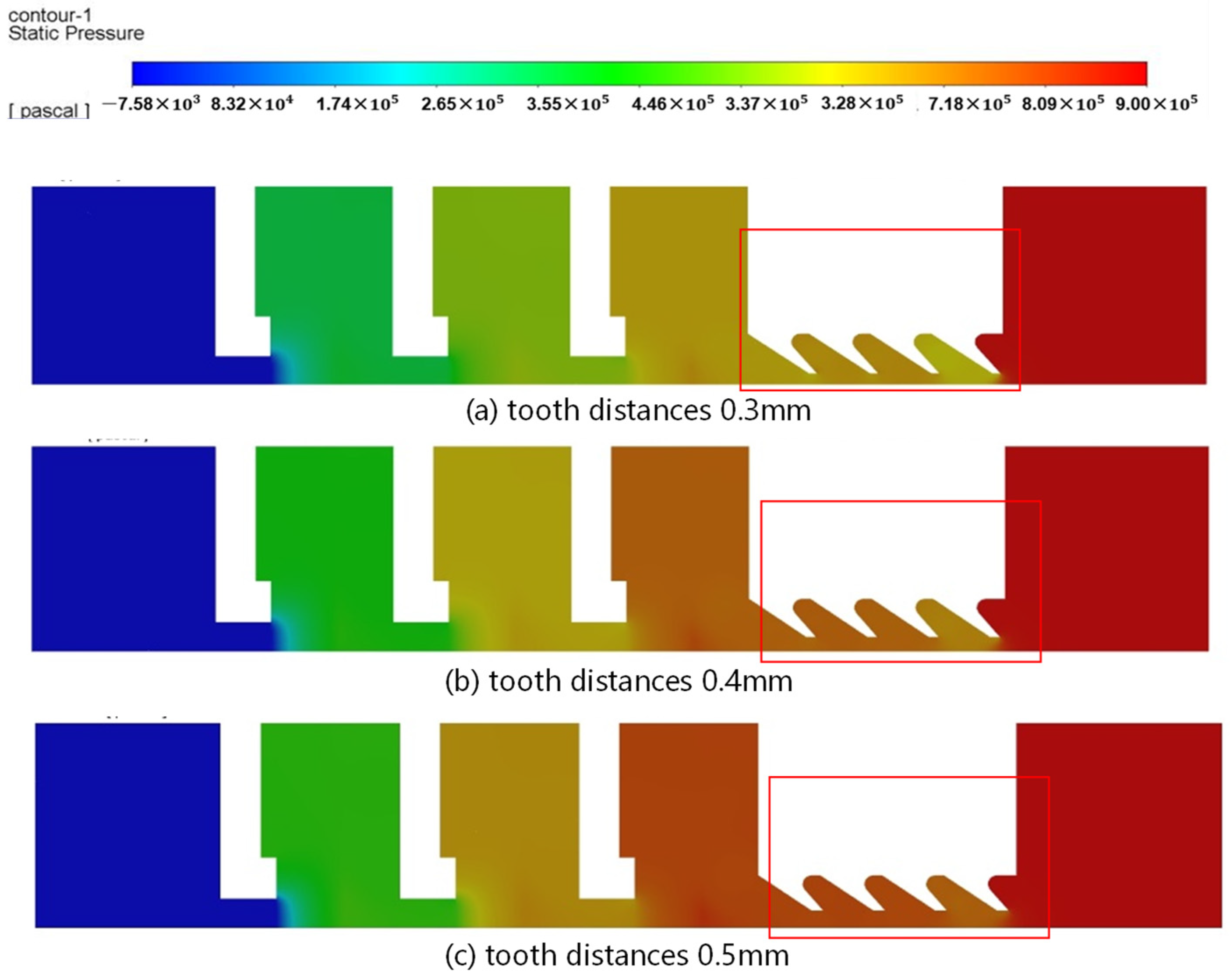
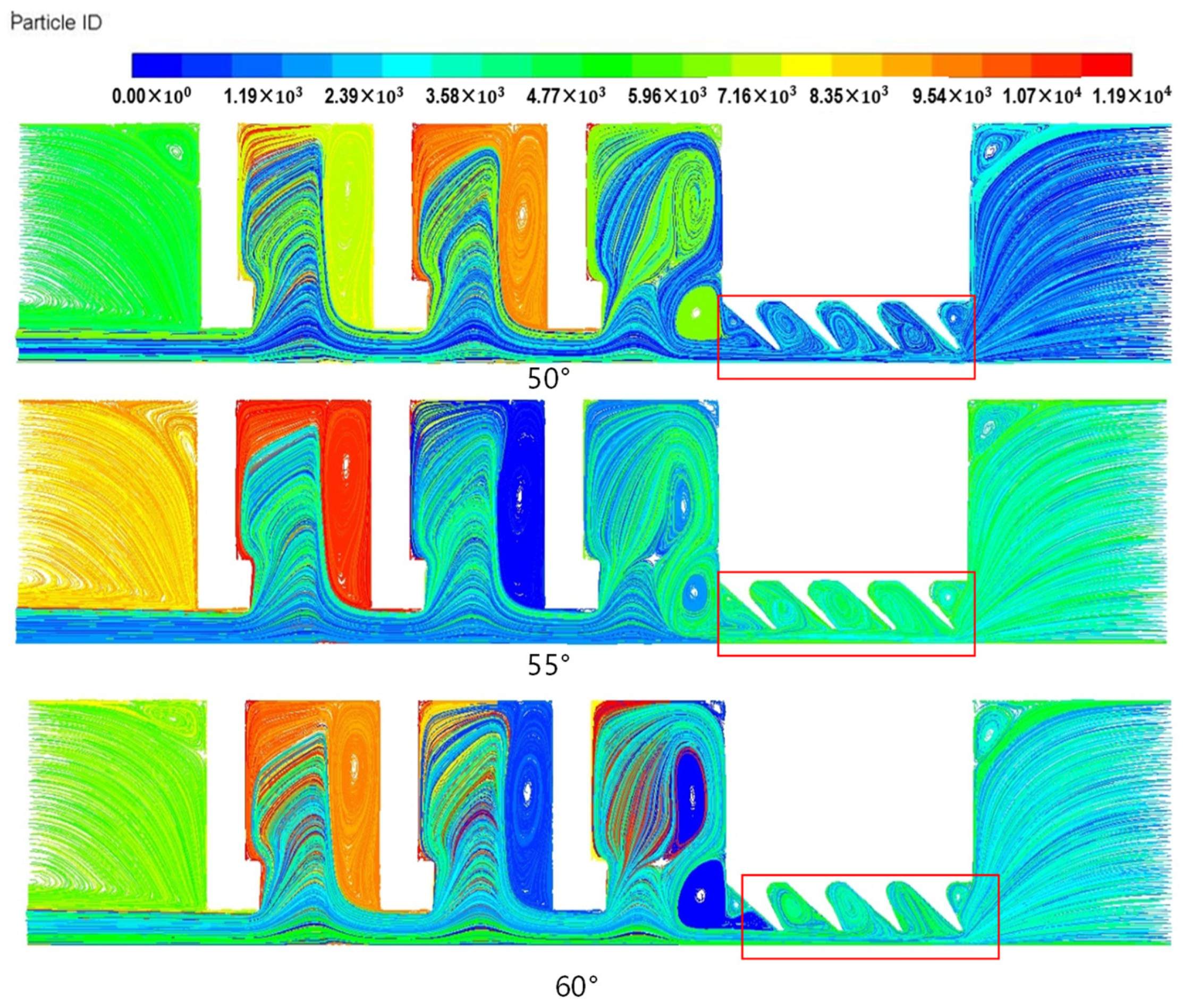
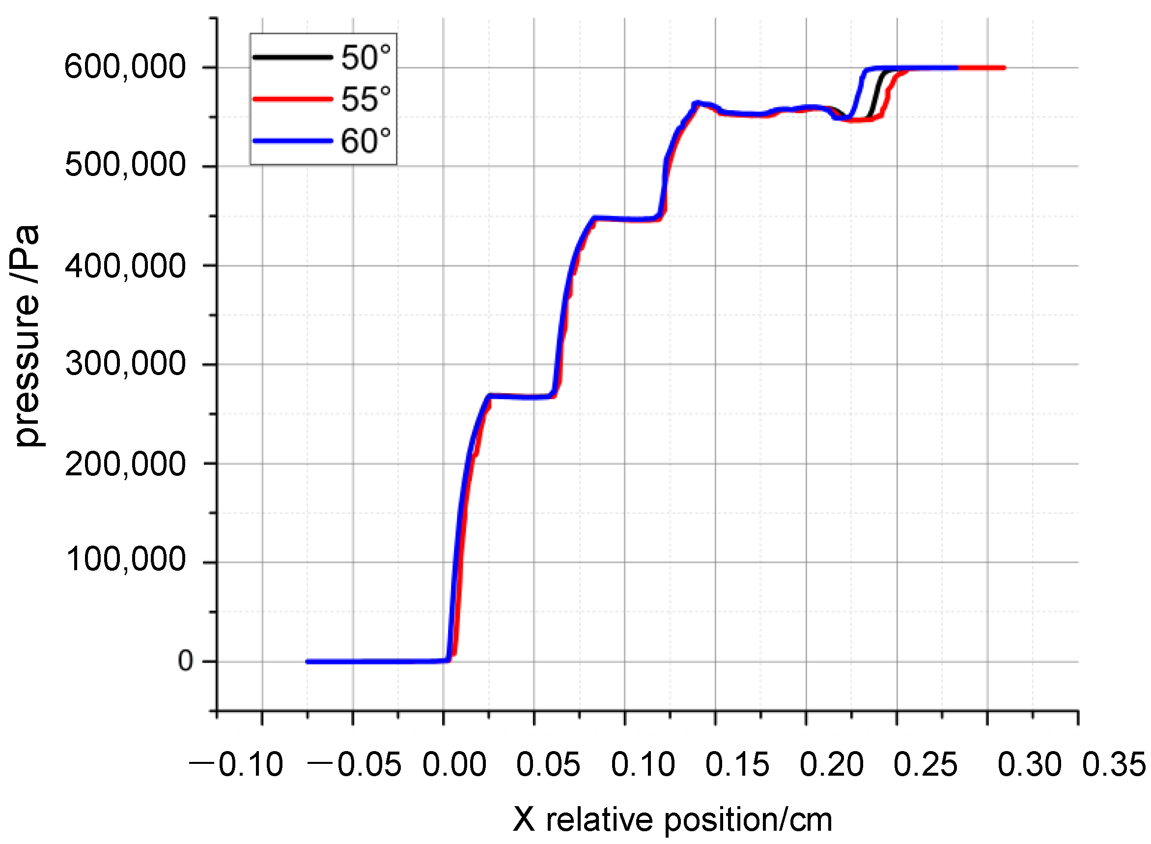
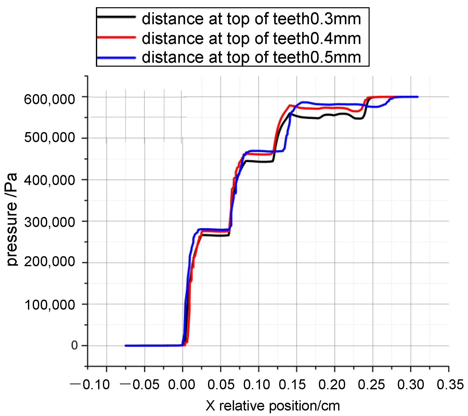
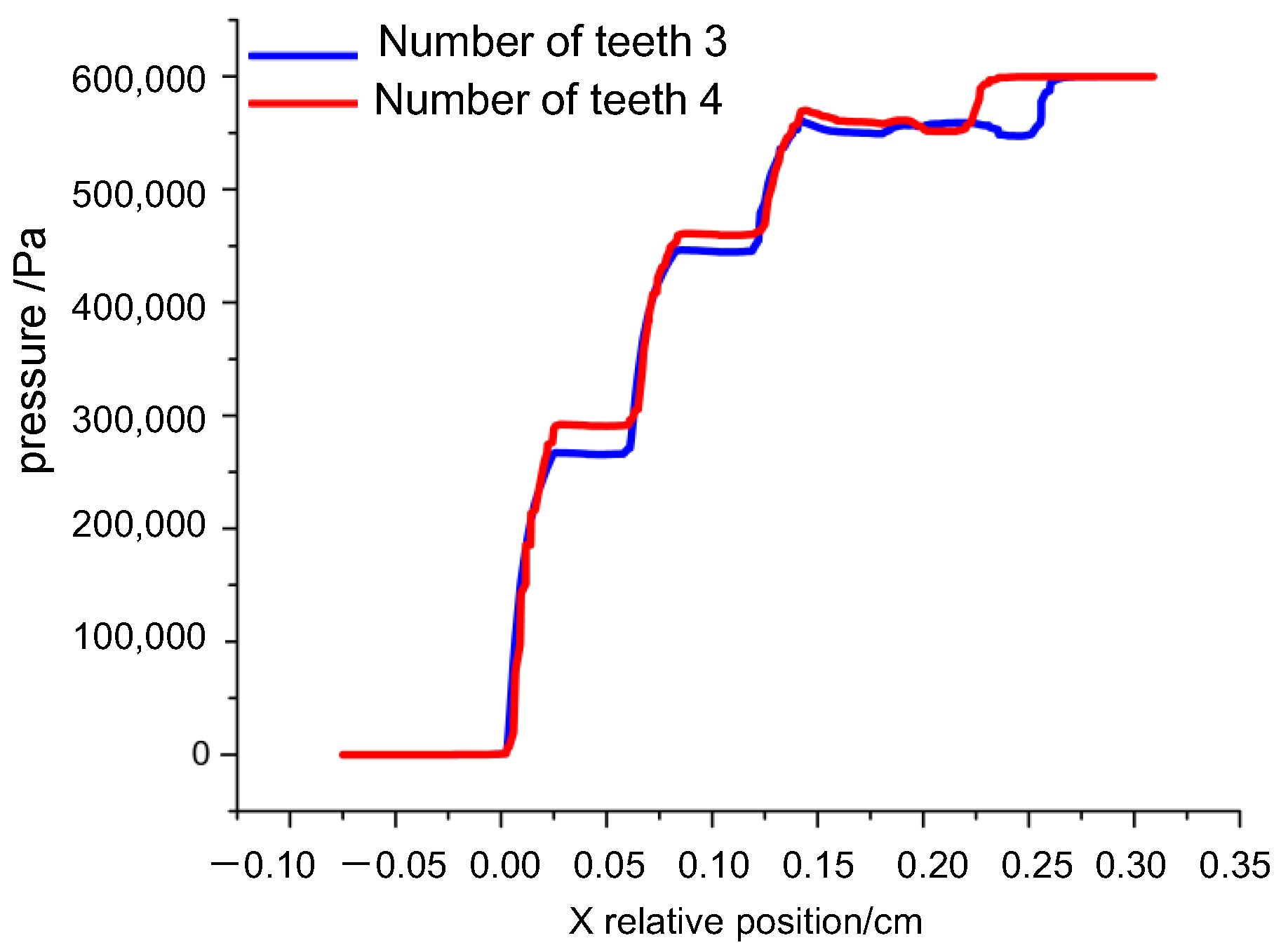
3.2.5. Grate Tooth Radial Distance, Number of Teeth, and Angle of Inclined Teeth

In the combined seal, the tooth-top throttling effect of the grate teeth and the vortex effect of the tooth cavity also contribute in part to the pressure drop and sealing performance. So, it is necessary to calculate their main structural parameters and analyze their influence on the pressure distribution and leakage of the combined seal.
Calculations show that with the reduction in the radial distance between the grate teeth and the increase in the number of grate teeth, the leakage rate of the combined seal is effectively reduced, while the angle of tooth inclination is insensitive to the leakage, as shown in Figure 28, Figure 29, Figure 30 and Figure 31. Calculations show that with the reduction in the radial distance between the grate teeth and the increase in the number of grate teeth, the leakage rate of the combined seal is effectively reduced, while the angle of tooth inclination is insensitive to the leakage, as shown in Figure 28, Figure 29, Figure 30 and Figure 31. The reduction in the radial distance of the grate teeth will enhance the top-of-the-tooth throttling effect, and the increase in the number of teeth can enhance the vortex effect of the tooth cavity, both of which can increase the effect on the dissipation of high-energy fluids, and thus reduce the leakage.
As shown in Figure 32, the change in the degree of inclination of the grate teeth has no obvious effect on the interstage pressure drop of the multistage brush bundle, because the change in the teeth’s angle does not produce obvious changes in dissipation, so the leakage rate and the pressure drop percentage in the grate teeth region barely change with the teeth’s angle. In turn, the uneven pressure drop characteristics of the three-stage brush bundle do not change obviously.
As shown in Figure 33, the distance between the teeth and rotos affects the pressure drop characteristics between the brush bundle stages. As the distance between the teeth increases, the pressure drop percentage in the grate teeth region gradually decreases, and the pressure drop percentage in the brush bundle region gradually improves, and the percentage of the first and second stages increases faster than that of the third stage. This is because, at an increased distance between the teeth, the top-of-the-teeth throttling effect is weakened and the conversion of the high-energy fluid pressure into kinetic energy through the grate teeth area is not effectively dissipated. High-speed fluid causes a downstream impact, the first and second brush bundle circulation area flow rate increases, and the brush bundle inertial damping-based dissipation with the flow rate increases, so the first and second pressure drop percentage increases. The weakening of the third stage is due to the fact that the first and second stages have absorbed the main fluid impacts in the front.
As shown in Figure 34, a reduction in the number of grate teeth can also slightly adjust the unevenness characteristic of the pressure drop of the combined seal. This is due to the reduced number of teeth, the insufficient dissipation in the grate region, the higher kinetic energy of the fluid at the outlet of the grate region, and the higher velocity of the incoming flow to the first and second-stage brush bundles resulting in an increase in dissipation.

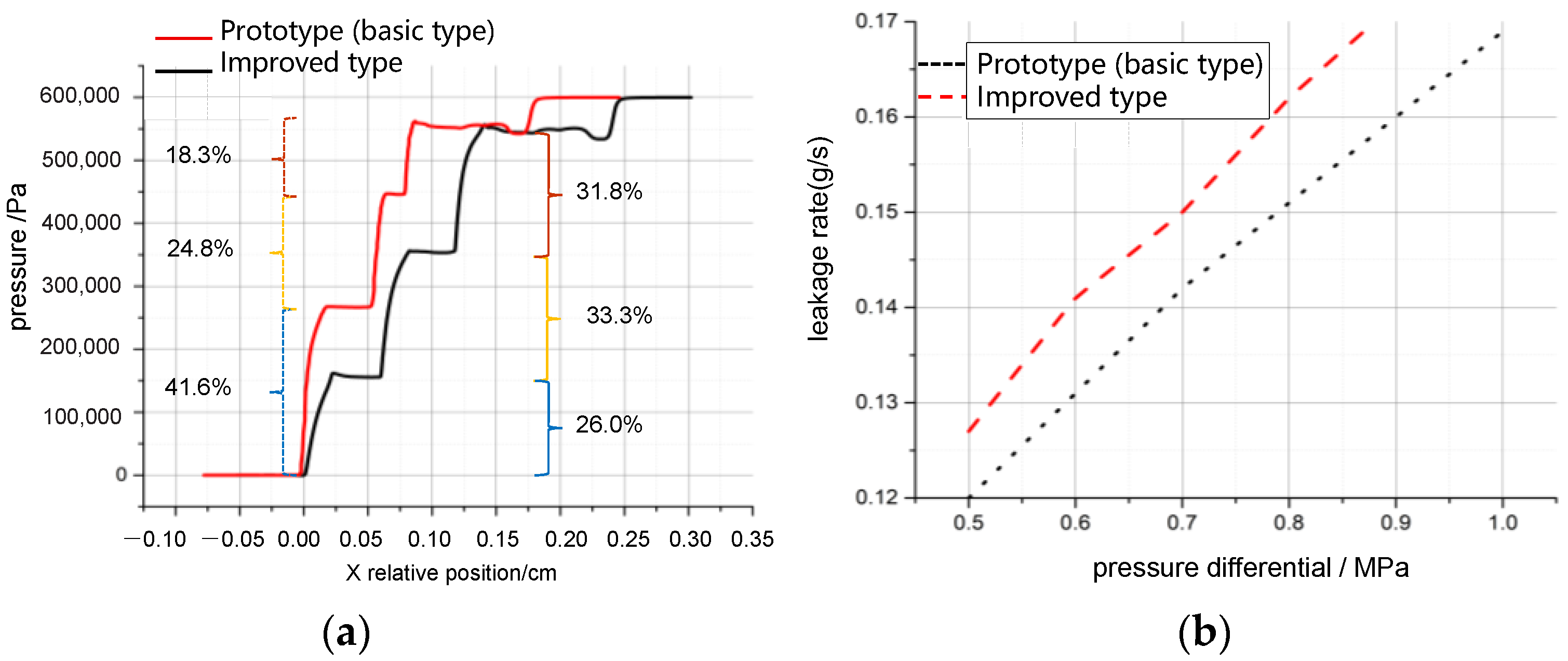
3.3. Calculation Conclusions and Parameter Improvements

3.3.1. Calculation Conclusions

In Section 3.2, the leakage rate and interstage pressure drop distribution characteristics of four-tooth three-stage brush combination seals are systematically calculated under varying structural parameters and operational conditions. The computational results demonstrate that: (1) The axial distance of brush bundles exhibits no significant impact on either the leakage rate or the unevenness characteristics of interstage pressure drop distribution. (2) While increased brush bundle thickness (including cumulative thickness across all stages) reduces leakage rate, only gradient-configured thickness across stages demonstrates marginal adjustment capability for interstage pressure drop distribution. (3) Radial clearance adjustment between brush bundles serves as an effective method for improving pressure drop unevenness characteristics, though such clearance configurations inevitably increase leakage rate—notably, first- and second-stage clearance adjustments induce smaller leakage increments compared to third-stage modifications. (4) The backplate height elevation effectively reduces localized brush bundle pressure drop percentages, albeit with concurrent leakage rate elevation. (5) The grate teeth component contributes to fluid energy dissipation and enhances the overall seal pressure-bearing capacity. (6) A reduction in tooth quantity and radial clearance proves beneficial for pressure drop uniformity optimization, though tooth reduction inversely elevates leakage rate. (7) The grate teeth inclination angle demonstrates negligible influence on both pressure drop equalization characteristics and leakage rate performance.
In conclusion, the radial clearance of the brush bundle and the height of the backplane are effective parameters to improve the unevenness characteristic of the pressure drop of the multi-stage brush bundle, but the evenness characteristic needs to be reduced at the cost of the sealing performance.
The calculation results show the structural parameters that can be used to regulate the interstage pressure drop unevenness characteristic of the combined seal, elaborate the adjustment effectiveness of the parameters, explain the mechanism of parameter adjustment, and point out that the leakage rate is the concomitant condition of adjustment, which provides a reference basis for improving the structural parameters of the multi-stage brush seal and improving the interstage pressure drop unevenness characteristic.

3.3.2. Parameter Improvements

The aim is to achieve the goal of combining seals, with a lower incremental cost of leakage rate, for significant improvement of pressure drop evenness between brush bundles. According to the law of the influence of different structural parameters on the interstage pressure drop of multistage brush seals in Section 3.2, the structural parameters are improved for the four-tooth three-stage brush combination seal, which has the same values of thickness of brush bundle, axial distance, radial clearance, and height of backplate in each stage. The adjustment and improvement of the seal structure parameters use the method of ‘axial dimensions’ to compensate for ‘radial dimensions’, and ‘non-gradient setting of brush bundle parameter’. It is necessary to increase the thickness of the first-stage brush bundle, in order to enhance the viscous damping dissipation of the first-stage brush bundle and to compensate for the increase in leakage rate, which is caused by the radial clearance setting of the brush bundle in the subsequent stages. At the same time, it is necessary to reduce the height of the first-stage backplane to enhance the fluid velocity in the first-stage brush bundle, which in turn increases the inertial damping dissipation of the first stage and compensates for the rising leakage rate caused by the increase in the height of the second- and third-stage backplanes. And the thicknesses, radial clearances, the heights of the backplanes of the second- and third-stage are adjusted according to the law of pressure drop unevenness in Section 3.2, instead of being enlarged or reduced stage-by-stage. For the complexity of the unevenness characteristics of the interstage pressure drop distribution, the flexible adjustment of the structural parameters is more reasonable and effective in improving the interstage pressure drop distribution.
In the improved combined seal, the thickness of the first-, second-, and third-stage brush bundles are set to 2.3 mm, 2.2 mm, and 2.2 mm, and the height of the backplane of the brush bundle is set to 0.6 mm, 0.8 mm, and 0.9 mm, and the radial clearance of the brush bundle is set to 0.00 mm, 0.05 mm, and 0.07 mm, other structural parameters do not change. A comparison of the structural parameters of the improved and prototype combined seals is shown in Table 3.
For the improved combined seal structure, its interstage pressure drop distribution and leakage rate are calculated using the numerical model in Section 2.2, and a comparison of the characteristics of the improved combined seal and the prototype combined seal is shown in Figure 35. Calculations show that the pressure drops in the first, second and third brush bundles of the prototype combined seal are 18.3%, 30.0% and 43.3%, respectively, while the pressure drops in the brush bundle of the improved combined seal are 31.8%, 33.3% and 26.0%, respectively. The highest pressure drop percentage of the brush bundle for the improved combination seal is reduced by 23%, and the interstage pressure drop distribution is significantly more balanced. For the improved combined seal, the risk of brush bundle premature failure caused by the unevenness characteristic of the pressure drop between stages is significantly reduced, and the pressure tolerance of the multi-stage brush bundle is significantly improved. Meanwhile, the leakage rate of the improved combined seal increased by 5.8% compared with the prototype due to the setting of radial clearance of the brush bundle in the rear stage, and the increase in leakage rate was small. The improved combined seal achieves the goal of sacrificing a smaller sealing performance for the balanced characteristics between the multi-stage brush bundle stages.

4. Mechanism Analysis of Unevenness Characteristic of Interstage Pressure Drop of Multistage Brush Seals

In the previous section, we analyzed the non-uniform pressure drop characteristics and leakage behavior of the four-tooth three-stage brush seal assembly. The influence of structural parameters on pressure drop distribution and leakage rate was revealed, with key parameters identified for effectively adjusting pressure drop non-uniformity. Structural parameter modifications were implemented to balance sealing performance and pressure drop uniformity. In this section, a mathematical relationship between pressure drops and entropy generation is derived from thermodynamic principles, aiming to introduce how entropy generation affects pressure drop behavior.
As shown in Figure 36, assuming that an ideal gas flows steadily and adiabatically through a small segment of the brush bundle (brush wire clearance), according to the law of conservation of mass, the first law of thermodynamics, and the second law of thermodynamics, we obtain:
m ˙ i n = m ˙ o u t h i n = h o u t S ˙ g e n = m ˙ s o u t s i n
By the definitions of enthalpy and entropy:
d h = T d s + v d P d s = 1 T d h v T d P
Then, the entropy increase is:
S ˙ g e n = m ˙ s o u t s i n = m ˙ i n o u t v T h = c o n s t a n t d P = m ˙ o u t i n v T h = c o n s t a n t d P
Since the gas flowing through the brush bundle is assumed to be ideal air, the equation of state is:
P v = R T
In other words:
v T = R P
From Equations (11)–(15):
S ˙ g e n = m ˙ R l n P i n P o u t = m ˙ R l n P o u t + P P o u t
Then, there is:
P = P o u t ( e S g e n / R 1 )
where P o u t and R are constants. Equation (17) shows that there is a nonlinear relationship between the entropy increase caused by the irreversible dissipation of the brush bundle and the seal pressure drop for a unit flow of energetic fluid in the brush wire clearance. The pressure drop increases exponentially with the entropy increase.
Moreover, because in multistage brush seals, ∆P follows from Equation (3) as:
P = 32 μ l L 1 D T 3 + D T D f 2 D f 1 v s λ m a x * 1 + D T + 3 2 + 1 β 4 5 2 β 2 ρ v s 2 2 2 D T L 0 D T 1 λ ¯ 1 D T 2 = A v s + B v s 2
In the equations:
A = 32 μ l L 1 D T 3 + D T D f 2 D f 1 1 λ m a x * 1 + D T
B = 3 2 + 1 β 4 5 2 β 2 ρ 2 2 D T L 0 D T 1 λ ¯ 1 D T 2
For the brush bundle of a brush seal, A and B are constants at steady state.
From (17) and (18) the unit flow fluid is given:
S g e n = R l n ( A v s + B v s 2 P o u t + 1 )
Equations (18) and (19) indicate that the entropy increasing S g e n and pressure drop P increase with the increase in fluid velocity in the brush wire clearance. In a multistage brush seal, from the high-pressure upstream to the low-pressure downstream, high-energy fluid potential energy is gradually converted to kinetic energy; kinetic energy is dissipated into heat by the brush wire surface layer of the damping and the back of the brush wire is separated from the turbulence of the annihilation of inertial damping, and the entropy value is gradually increased. The differential pressure increases stage-by-stage, the pressure drop increases quickly with the increase in entropy, and then the multistage brush bundle emerges with an unevenness in the pressure drop stage-by-stage.
As mentioned before, increasing the brush bundle thickness, decreasing the backplane height, and decreasing the brush bundle radial clearance can enhance the viscous and inertial damping dissipation of the gas flow within the brush bundle. This process increases the entropy of the gas flow through the brush bundle, ultimately raising the pressure drop percentage at the local stage. Therefore:
(1)
Increasing the thickness of the brush bundle and decreasing the backplane height in the upstream stage amplifies dissipation and pressure drop in that stage;
(2)
Increasing the radial clearance and baffle height in the downstream stage reduces dissipation and pressure drop in that stage;
(3)
These adjustments collectively improve the pressure drop uniformity across stages in multistage brush seals, aligning with the optimization strategy proposed in Section 3.3.

5. Summary

The paper focuses on the problem of premature seal failure caused by the unevenness of the interstage pressure drop of a multistage brush seal; established a numerical calculation model of a four-tooth three-stage brush combination seal; calculated the pressure distribution, flow field distribution, flow traces, leakage rate, and interstage pressure drop distribution of the combination seal with different structural parameters and working condition parameters; analyzed the sealing mechanism of the combination seal and the unevenness characteristic of interstage pressure drop, and improved the combination seal with structural parameters; and elaborated the mechanism of the unevenness of the interstage pressure drop of a multi-stage brush bundle from the perspective of entropy increase. Specifically:
(1)
In the four-tooth three-stage brush combined seal, the high-pressure fluid dissipation includes tooth cavity vortex dissipation, tooth-tip throttling dissipation, brush bundle viscous damping dissipation, and inertial damping dissipation, with the latter two being the primary dissipations.
(2)
For the prototype combined seal in different pressure ratio conditions, the first, second, and third stage of the brush bundle pressure drop percentage are about 18.3%, 33.0%, and 43.3%, the grate tooth are of the pressure drop percentage is 8.4%, and the pressure drop between the stages of the combination seal exhibits an obvious unevenness.
(3)
In combined seals, changes in the brush bundle axial distance and tooth inclination angle show no significant effect on leakage rate and inter-stage pressure drop distribution; the gradient setting of brush bundle thickness, as well as the number of teeth and the size of tooth tip clearance exhibit certain influences on pressure drop distribution; changes in the brush bundle radial clearance and backplane height exert the most visible effect on the adjustment of pressure drop imbalance; additionally, improvements in pressure drop equalization characteristics between brush bundles at different stages are often accompanied by an increase in seal leakage rate.
(4)
By cross-compensating the axial and radial dimensions of the brush bundle and setting the parameters of each stage in a non-gradient design, the goal of equalization the pressure drop between stages can be achieved at the cost of a small increase in leakage rate. The improved seal shows a 5.8% increase in leakage rate and a 23% reduction in maximum brush bundle pressure drop compared to the prototype.
(5)
In multi-stage brush seals, viscous damping dissipations and inertial damping dissipations of the brush bundle lead to an increase in the entropy value of the leakage gas, and the pressure drop increases nonlinearly by stages as the entropy value increases.
(6)
Compared to traditional methods, the leakage rate of the improved seal increased by only 5.8%, while the backplane height of the improved design (0.6 mm) remains greater than the typical radial clearance of labyrinth seals (0.3 mm), ensuring the practical feasibility of the modified design in engineering applications. This indicates that reducing the height of the first-stage backplane to enhance the inter-stage pressure drop characteristics of multistage brush seals holds significant engineering value.

Author Contributions

Conceptualization, C.G. and Y.M.; methodology, C.G. and Y.M.; software, C.G.; validation, Y.M.; formal analysis, W.Z.; investigation, X.S.; resources, Y.M.; data curation, C.G.; writing—original draft preparation, C.G; writing—review and editing, C.G and Y.M.; visualization, B.H.; supervision, Q.Z.; project administration, Q.Z.; funding acquisition, Q.Z. All authors have read and agreed to the published version of the manuscript.

Funding

This study is supported by the National Natural Science Foundation of China (12402408) and the State Key Program of National Natural Science Foundation of China (No. 52236005).

Institutional Review Board Statement

Not applicable.

Informed Consent Statement

Not applicable.

Data Availability Statement

The original contributions presented in the study are included in the article, further inquiries can be directed to the corresponding author.

Conflicts of Interest

The authors declare no conflict of interest.

Appendix A. Detailed Derivation of Fractal Geometry Models for Porous Media

(1)
Fractal Geometry Theory
The interstitial spaces within brush seal bristle packs are intricate and microscale. The structural similarity between porous media and bristle packs has led to the widespread use of porous media models for simulating leakage flow in brush seals. However, the capillary diameter, tortuosity, and surface morphology of porous media pores exhibit inherent randomness and irregularity, making traditional theoretical methods inadequate for analyzing their seepage characteristics. Given the fractal nature of porous microstructures and pore size distributions [22,23,24], advancements in fractal geometry offer novel approaches to refine porous media models for brush seals.
A fractal-geometry porous medium refers to a structure where the microarchitecture (e.g., pore sizes in the bristle pack) follows a fractal scaling law within a defined dimensional range [25]. Specifically, the cumulative number of pores with diameters greater than or equal to λ satisfies:
M L ~ L D f
where Df is the fractal dimension, M(L) represents the structural characteristic measure of the medium, and L denotes the scale.
When the measurement scale L changes, the measure M(L) of the fractal object varies, but the fractal dimension Df remains constant. Taking the logarithm of both sides of Equation (A1) yields a straight line in a log-log coordinate system, where the slope corresponds to Df. Yu B M [24] applied fractal geometry theory to porous media pores, demonstrating that the cumulative number of pores with diameters greater than or equal to λ satisfies:
N L λ = λ m a x λ D f
where Df is the fractal dimension, satisfying 0 < Df < 2 in two-dimensional space and 0 < Df < 3 in three-dimensional space; λ denotes the pore scale, and λmax is the maximum pore scale.
From Equation (A2), the total number of pores is derived as:
N t = λ m a x λ m i n D f
where λmin represents the minimum pore scale.
Equation (A3) quantifies the total pore count in a fractal-geometry porous medium and implies statistical self-similarity within the scale range λminλλmax, where the fractal dimension Df remains constant.
Treating Equation (A2) as a continuous and differentiable function, differentiation with respect to λ yields:
d N = D f λ m a x D f λ D f + 1 d λ
This equation describes the number of pores within the interval [λ, λ + ], where −dN > 0, indicating that the pore count decreases as the pore diameter increases.
d N N t = D f λ m i n D f λ D f + 1 d λ = f λ d λ
where f λ = D f λ m i n D f λ D f + 1 is the probability density function of the pore distribution, which should satisfy the normalization condition:
+ f λ d λ = λ m i n λ m a x f λ d λ = 1 λ m i n λ m a x D f = 1
The condition for the above equation to hold is:
λ m i n λ m a x D f 0
This equation can be regarded as a criterion for determining whether fractal geometry theory and methods are applicable to porous media. In brush seals, λ m i n / λ m a x < 10 2 , so λ m i n / λ m a x D f 0 , thereby approximately satisfying Equation (A7). Therefore, the porous medium in brush seals can be treated using fractal theory and methods. The value of Df is calculated by the following equation [25]:
D f = d ln ln λ m i n λ m a x
where ∅ is the porosity and d is 2 in two dimensions and 3 in three dimensions.
When a gas flows in the pores of a porous medium, its flow path may be curved, and Wheatcraft [26] obtained the fractal scalar relationship for the characteristics of a tortuous flow pipe in a porous medium, which is given by:
L t = λ m i n 1 D t L D T
τ = L t L = L λ m i n D T 1
In the equations, DT represents the tortuosity fractal dimension 1 < D T < 2 , L is the characteristic length of the channel, and Lt denotes the length of the capillary channel with diameter λ. Generally, Lt > L. Equations (A9) and (A10) characterize the curvature of capillary fluid flow paths in porous media. When DT = 1, the fluid flows along a straight path. A higher DT value indicates stronger streamline curvature, and at the maximum limit (DT = 2), the streamlines fully occupy the two-dimensional plane. In Equation (A10), λmin represents the minimum pore (capillary) size, which is a finite value. Therefore, the ratio Lt/L is also finite.
(2)
Theory of fractal geometry porous media
① Viscous Damping Dissipation:
The fractal model of porous media capillaries involves two structural parameters: the pore fractal dimension Df and the tortuosity fractal dimension DT. The total flow rate Q through a unit volume of porous media is derived by conceptualizing fluid flow as occurring through tortuous capillary channels whose size distribution follows a fractal scaling law. Based on the modified Hagen-Poiseuille equation [23], the flow rate through a single tortuous capillary can be expressed as:
q λ = π 128 p 1 L t λ 4 μ
In the equation, Δp1 represents the pressure variation (unit: Pa); λ denotes the pore diameter (unit: mm); lₜ indicates the total length of the tortuous capillary (unit: mm); and μ stands for the fluid viscosity coefficient (unit: Pa·s).
Equation (A11) is derived by approximating the capillary as circular. For cross-sectional shapes other than circular, they can be converted into a mean hydraulic radius model, yielding equations of identical form. Since the pore channel sizes follow a fractal distribution, the total flow rate Q can be obtained by integrating the flow rate in a single tube from the minimum pore diameter λmin to the maximum pore diameter λmax:
Q = λ m i n λ m a x q λ d N λ = π 128 μ p 1 L D f 3 + D T D f L 0 1 D T λ m a x 3 + D T 1 λ m i n λ m a x D f λ m i n λ m a x 3 + D T 2 D f
In the equation, Df represents the fractal dimension of the two-dimensional medium; DT denotes the tortuosity fractal dimension; λmax is the maximum pore diameter (unit: mm); and λmin is the minimum pore diameter (unit: mm). Since the tortuosity satisfies 1 < DT < 2 and the fractal dimension in two dimensions satisfies 1 < Df < 2, the exponent 3 + DT − 2Df > 0. Furthermore, because 0 < λ m i n λ m a x 3 + D T 2 D f < 1 , Based on Yu and Li’s judgment ( λ m i n / λ m a x < 10 2 ), Then, λ m i n λ m a x D f λ m i n λ m a x 3 + D T 2 D f 0 It can be neglected. Equation (A12) can be simplified as:
Q = π 128 μ p 1 L 0 D f 3 + D T D f L 1 D T λ m a x 3 + D T
Since the apparent velocity vs = QA and there is A = Ap⁄∅ in any cross-section, where A is the total area of the cross-section, ∅ is the porosity, and Ap is the total area of the pores, then:
A p = λ m i n λ m a x π λ 2 4 d N = π D f 4 2 D f λ m a x 2 1 λ m i n λ m a x 2 D f
The total area is:
A = π D f 4 2 D f λ m a x 2 1 λ m i n λ m a x 2 D f
And because the porosity is:
= λ m i n λ m a x 2 D f
So, for the flows through the total cross-sectional area A can be expressed as:
A = π 4 D f 2 D f 1 λ m a x 2
The apparent velocity of a fluid in a fractal geometry porous medium is:
v s = Q A = 1 32 μ p 1 L 2 D f 3 + D T D f ε 1 ε L 0 1 D T λ m a x 1 + D T
where Q is the flow rate, m3/s; A is the total cross-sectional area through which the flow passes, m2; ε is the porosity, %.
The pressure drop is obtained from Equation (A18) as:
  p 1 L = 32 μ v s L 1 D T 3 + D T D f 2 D f 1 1 λ m a x 1 + D T
where vs is the apparent seepage velocity, m/s; D f = 2 ln / ln λ m i n λ m a x .
The part framed by the dotted line as shown in Figure A1 is a unit with area:
Figure A1. Hole-throat model.
Applsci 15 03899 g0a1
A 1 = π D p 2 4 1
where Dp is the average diameter of the particles, mm. the maximum area of the hole is:
A p , m a x = A 1 π D p 2 4
If approximated as a circle, the area of the largest hole can be expressed as:
A p , m a x = π λ m a x 2 4
It is obtained from Equations (A20)–(A22):
λ m a x = D p 1
Equation (A23) is a model for the largest possible pore size, which shows that if the porosity is 0, the diameter of the largest pore is also 0. If the porosity is 1, the diameter of the largest pore is infinite, and these are consistent with reality. The equation also shows that the maximum pore diameter is directly proportional to the particle size, which is also consistent with reality.
In fact, the brush wire is not spherical, so the maximum diameter of the pore should be divided by the shape factor ∅s to obtain a corrected maximum diameter of:
λ m a x * = D p s 1
Substituting equation above into Equation (A19) yields:
p 1 l = 32 μ L 1 D T 3 + D T D f 2 D f 1 v s λ m a x * 1 + D T
where vs is the seepage velocity, m/s; μ is the viscous coefficient of the fluid, Pa∙s.
Equation (A25) describes the pressure drop caused by viscous energy loss in porous media flow, i.e., viscous damping dissipation. Compared with the first term of the Ergun equation for porous media [4,5], this equation eliminates the empirical constant C and reveals the factors influencing viscous damping-induced losses, including fluid viscosity, pore size, fractal dimension of capillary tortuosity, and fractal dimension of pores. Equation (A25) also indicates that the pressure drop becomes zero when porosity ∅ = 1, while approaching infinity as porosity tends to zero, which aligns with the physical reality of brush bundles.
② Inertial damping loss:
Previous analyses treated porous media pores as uniform-diameter tubes with constant capillary diameters. However, real porous media cannot maintain constant-diameter capillaries, making local losses (i.e., inertial damping dissipation) non-negligible. We therefore attribute inertial damping dissipation to variations in pore throat geometry within capillaries. Figure A1 shows an idealized pore-throat model with a pore-throat ratio:
β = 1 1 4 1 π
The total inertial damping loss is:
h f = h f e + h f c = ξ c + ξ e v ¯ 2 2 g = 3 2 + 1 β 4 + 5 2 β 2 v ¯ 2 2 g
Consider the curvature of the capillary, then:
h f = 3 2 + 1 β 4 + 5 2 β 2 v ¯ t 2 2 g
The pressure drop over the length l caused by the orifice throat is:
Δ p 2 = ρ g h f = 3 2 + 1 β 4 5 2 β 2 ρ v ¯ t 2 2
where β is the orifice-throat ratio, v ¯ t is the mean velocity, m/s; h f is the local inertia damping loss, mm.
The average flow velocity in a straight pipe with linear velocity is:
v ¯ = d L d t
v ¯ t = d L t d t = D T L 0 D T 1 λ ¯ 1 D T v ¯
where λ ¯ is the mean capillary diameter, mm, which can be derived from the probability density relationship:
λ ¯ = λ m i n λ m a x λ f λ d λ = D f D f 1 λ m i n 1 λ m i n λ m a x D f 1
Substituting Equation (A31) into Equation (A32) gives:
Δ p 2 = ρ g h f = 3 2 + 1 β 4 5 2 β 2 ρ 2 D T L 0 D T 1 λ ¯ 1 D T 2 v ¯ 2
Substituting the relationship v ¯ = v s between the apparent velocity v s in the porous medium and the average velocity (i.e., pore velocity) v ¯ in the tube into Equation (A33) yields:
Δ p 2 = ρ g h f = 3 2 + 1 β 4 5 2 β 2 ρ v s 2 2 2 D T L 0 D T 1 λ ¯ 1 D T 2
In Equation (A34) Δ p 2 represents the change in differential pressure over a length l when passing through an orifice throat, so the pressure drop per unit length can be expressed as:
Δ p 2 l = ρ g h f = 3 2 + 1 β 4 5 2 β 2 ρ v s 2 2 2 1 l D T L 0 D T 1 λ ¯ 1 D T 2
where l is the length of the pore throat, mm; v s is the apparent velocity of the pore throat, m/s.
Equation (A35) represents the pressure loss caused by inertial damping dissipation. Compared with the second term of the Ergun equation [4,5], this equation eliminates empirical constants, assigns explicit physical meanings to each term, and demonstrates that the pressure drop is proportional to the square of velocity.
From Equations (A25) and (A35), the total pressure drop loss can be derived as the sum of viscous damping dissipation per unit length and inertial damping dissipation per unit length:
p 1 l + p 2 l = 32 μ L 1 D T 3 + D T D f 2 D f 1 v s λ m a x * 1 + D T + 3 2 + 1 β 4 5 2 β 2 ρ v s 2 2 2 1 l D T L 0 D T 1 λ ¯ 1 D T 2

References

  1. Li, J.; Li, Z.; Zhang, Y. Research progress of brush seal technology. Aeroengine 2019, 45, 74–84. [Google Scholar]
  2. Chupp, R.E.; Ghasripoor, F.; Turnquist, N.A.; Demiroglu, M.; Aksit, M.F. Advanced seals for industrial turbine applications: Dynamics seal development. J. Propuls. Power 2002, 18, 1260–1266. [Google Scholar] [CrossRef]
  3. Dinc, S.; Demiroglu, M.; Turnquist, N.; Mortzheim, J.; Goetze, G.; Maupin, J.; Hopkins, J.; Wolfe, C.; Florin, M. Fundamental design issues of brush seals for industrial applications. ASME J. Turbomach. 2002, 124, 293–300. [Google Scholar] [CrossRef]
  4. Bayley, F.J.; Long, C.A. A combined experimental and theoretical study of flow and pressure distributions in a brush seal. ASME J. Eng. Gas Turbines Power 1993, 115, 404–410. [Google Scholar] [CrossRef]
  5. Turner, M.T.; Chew, J.W.; Long, C.A. Experimental investigation and mathematical modeling of clearance brush seals. ASME J. Eng. Gas Turbines Power 1998, 120, 573–579. [Google Scholar]
  6. Sun, X.; Li, W.; Liu, X. Design and test of brush seal. Aeroengine 2005, 31, 17–19. (In Chinese) [Google Scholar]
  7. Zhao, H.; Jiao, Z.Z.; Sun, D.; Liu, Y.; Zhan, P.; Xin, Q. Numerical and experimental research on interstage pressure drop distribution affecting factors of multi-stage brush seals. Acta Aeronaut. Astronaut. Sin. 2020, 41, 123544. (In Chinese) [Google Scholar]
  8. Pugachev, A.O.; Deckner, M. Experimental and theoretical rotordynamic stiffness coefficients for a three-stage brush seal. Mech. Syst. Signal Process. 2012, 31, 143–145. [Google Scholar] [CrossRef]
  9. Wang, K.; Yang, Y.; Suo, S.; Jiang, J. Research on flow calculation and configuration of system parameters of two-stage brush seal. Lubr. Seal. 2017, 42, 43–47. [Google Scholar]
  10. Wen, L.; Wang, Z.L.; Ding, L.; Liu, J.; Hu, G.; Chen, C. Inter-stage imbalance analysis of tow-stage low hysteresis brush seal. J. Beijing Univ. Aeronaut. 2014, 40, 1154–1159. (In Chinese) [Google Scholar]
  11. Qiu, B.; Li, J.; Feng, Z.; Jiang, S.; Kong, X. Experimental and numerical study of leakage characteristics of two-stage brush seals. J. Xi’an Jiaotong Univ. 2013, 47, 7–12. [Google Scholar]
  12. Raben, M.; Friedrichs, J.; Helmis, T.; Flegler, J. Brush seals used in steam environments-chronological wear development and the impact of different seal designs. J. Eng. Gas Turbines Power 2016, 139, 051901. [Google Scholar]
  13. Li, G.; Sun, D.; Jiao, Z.; Du, C.; Bai, L. Numerical study on the flow heat transfer characteristics of multi-stage low hysteresis type brush seals. Fan Technol. 2019, 61, 56–63. [Google Scholar]
  14. Zhang, G.; Sun, D.; Jiao, Z.; Du, C.; Bai, L. Numerical and experimental study on the flow heat transfer characteristics of two-stage brush seals. Fan Technol. 2020, 62, 44–52. [Google Scholar]
  15. Jiao, Z. Numerical and Experimental Study on the Equilibrium Characteristics of Critical Bearing Pressure and Interstage Pressure Drop of Brush Seal. Master’s Thesis, Shenyang University of Aeronautics and Astronautics, Shenyang, China, 2020. [Google Scholar]
  16. Yan, S.; Hu, F.; Huang, S.Q.; Liu, S.W. Leakage and inter-stage imbalance analysis of two-stage brush seals structure based on CFD and neural network! Aerengine 2022, 48, 70–75. [Google Scholar]
  17. Li, Y.; Zhao, H.; Sun, D.; Mu, W.; Ma, T.; Hu, G. Numerical and experimental study on the heat transfer characteristics of multi-stage brush seal interstage flow. J. Aerosp. Dyn. 2024, 39, 20220308. [Google Scholar]
  18. Zhao, H.; Li, Y.; Sun, D.; Mu, W.; Ma, T.; Hu, G. Numerical and experimental study of pressure drop equalization between differentiated multistage brush seal stages. J. Aerosp. Dyn. 2022, 37, 934–945. [Google Scholar]
  19. Li, G.-H. Experimental and Numerical Study of Multistage Brush Seal Based on Pressure Drop Matching. Masters’ Thesis, Inner Mongolia University of Technology, Hohhot, China, 2024. [Google Scholar]
  20. Pan, J.; Zhang, J.; Sun, D.; Zhou, K.; Ma, L. Numerical and experimental study on leakage and pressure drop distribution characteristics of two-stage brush seals. Lubr. Seal. 2025. Available online: https://link.cnki.net/urlid/44.1260.th.20250210.1039.006 (accessed on 27 January 2025).
  21. Zhang, Y.; Wang, Y.; Yan, X.; Li, J. Study of brush seal leakage flow and heat transfer characteristics Part I: Leakage characteristics. J. Eng. Thermophys. 2017, 38, 482–489. [Google Scholar]
  22. Yu, B.M. Progress in fractal analysis of transport properties in porous media. Adv. Mech. 2003, 33, 333–346. [Google Scholar]
  23. Yu, B.M. Analysis of heat and mass transfer in fractal media (review). J. Eng. Thermophys. 2003, 24, 481–483. [Google Scholar]
  24. Mandelbrot, B.B. The Fractal Geometry of Nature. San Fr. Freeman Am. J. Phys. 1983, 51, 286. [Google Scholar] [CrossRef]
  25. Zou, M. Some Applications of Fractal Theory. Ph.D. Thesis, Huazhong University of Science and Technology, Wuhan, China, 2007. [Google Scholar]
  26. Wechsatal, W.; Lorente, S.; Bejan, A. Optimal tree-shaped networks for fluid flow in a disc-shaped body. Int. J. Heat Mass Transf. 2002, 45, 4911–4924. [Google Scholar]
Figure 1. Schematic diagram of four-tooth three-stage brush combination seal structure.
Applsci 15 03899 g001
Figure 2. Schematic diagram of the calculated fluid domain of a four-tooth three-stage brush seal combination.
Applsci 15 03899 g002
Figure 3. Schematic diagram of the computational domain meshing topology in chunks.
Applsci 15 03899 g003
Figure 4. Detail of mesh division of four-tooth three-stage brush seal combination.
Applsci 15 03899 g004
Figure 5. A structural model of the three-stage brush seal test piece from the literature.
Applsci 15 03899 g005
Figure 6. A comparison of the numerical calculations and experimental values of the structure of the three-stage brush seal test piece from the literature [7].
Applsci 15 03899 g006
Figure 7. Differential Pressure Leakage Characteristics Test Rig for Four-Tooth Three-Stage Brush-Type Combination Seals.
Applsci 15 03899 g007
Figure 8. The verification of the accuracy of the sealing characteristics of the numerical model for fractal geometry porous media.
Applsci 15 03899 g008
Figure 9. Pressure distribution of four-tooth three-stage brush combination seal (differential pressure 0.6 M Pa, gauge pressure).
Applsci 15 03899 g009
Figure 10. Vector cloud diagram of the flow velocity of four-tooth three-stage brush combination seal (differential pressure 0.6 M Pa, gauge pressure).
Applsci 15 03899 g010
Figure 11. Flow traces of four-tooth three-stage brush seal combination (differential pressure 0.6 MPa, gauge pressure).
Applsci 15 03899 g011
Figure 12. X-direction pressure distribution of the brush bundle of a four-tooth three-stage brush combination seal.
Applsci 15 03899 g012
Figure 13. Vector diagram of the flow velocity of the four-tooth three-stage brush seal combination with different axial distances.
Applsci 15 03899 g013
Figure 14. Effect of axial distance on leakage rate of combined seals.
Applsci 15 03899 g014
Figure 15. The effect of axial distance on the unevenness of pressure drop characteristics between combined seal stages.
Applsci 15 03899 g015
Figure 16. The impact of brush bundle thickness on the combined seal leakage rate.
Applsci 15 03899 g016
Figure 17. The effect of brush bundle thickness on pressure drop unevenness characteristics between combined seal stages (Ⅰ).
Applsci 15 03899 g017
Figure 18. Effect of Brush Bundle Thickness on Pressure Drop Irregularity Characteristics Between Combined Seal Stages (II).
Applsci 15 03899 g018
Figure 19. The pressure cloud of the combined seal with different brush bundle thicknesses.
Applsci 15 03899 g019
Figure 20. Vector diagram of flow velocity at different radial clearances.
Applsci 15 03899 g020
Figure 21. Effect of Brush Bundle Radial Clearance on Leakage Rate of Combined Seals.
Applsci 15 03899 g021
Figure 22. Illustrates the impact of radial clearance of the brush bundle on the uneven characteristics of pressure drop between combined seal stages (I).
Applsci 15 03899 g022
Figure 23. Illustrates the impact of radial clearance of the brush bundle on the uneven characteristics of pressure drop between combined seal stages (II).
Applsci 15 03899 g023
Figure 24. Pressure cloud of combined seal at different backplane heights.
Applsci 15 03899 g024
Figure 25. Influence of the height of the backplane of the brush bundle on the uneven characteristics of the pressure drop between the combined seal stages (I).
Applsci 15 03899 g025
Figure 26. The influence of the height of the backplane of the brush bundle on the uneven characteristics of the pressure drop between the combined seal stages (Ⅱ).
Applsci 15 03899 g026
Figure 27. Effect of height of backplane of brush bundle on leakage rate of combined seal.
Applsci 15 03899 g027
Figure 28. Influence of grate tooth structure parameters on combined seal leakage rate.
Applsci 15 03899 g028
Figure 29. Flow traces of combined seals with different radial tooth distances.
Applsci 15 03899 g029
Figure 30. Flow traces of combined seals with different numbers of teeth.
Applsci 15 03899 g030
Figure 31. Flow traces of combined seal for different tooth inclination angles.
Applsci 15 03899 g031
Figure 32. The effect of the degree of inclination of the grate teeth on the interstage pressure drop unevenness characteristics of the combined seals.
Applsci 15 03899 g032
Figure 33. Effect of radial teeth distance of grate teeth on unevenness characteristic of pressure drop between combined seal stages.
Applsci 15 03899 g033
Figure 34. The effect of the number of grate teeth on the unevenness characteristic of pressure drop between combined seal stages.
Applsci 15 03899 g034
Figure 35. A comparison of the calculation results of the improved combination seal and the prototype combination seal. (a) The pressure drop distribution of the interstage for improved and prototype combination seals, and (b) the leakage rates of the improved and prototype combination seals.
Applsci 15 03899 g035
Figure 36. Entropy increase in the clearance of the brush wires.
Applsci 15 03899 g036
Table 1. Structural parameters of four teeth-three stage brush combination seals.
Structural ParametersValues/mmStructural ParametersValues/mm
Outside diameter158Thickness of third-stage brush bundle1.8/2.0/2.2/2.4
Inside diameter138Height of backplane for first-stage brush bundle1.0/1.2
Axial distance of first-stage brush bundle1.5/1.8/2.0Height of backplane for second-stage brush bundle1.0/1.2/1.4
Axial distance of second-stage brush bundle1.5/1.8/2.0Height of backplane for third-stage brush bundle1.0/1.2/1.4
Axial distance of third-stage brush bundle1.5/1.8/2.0number of grate teeth3/4
Thickness of first-stage brush bundle2.0/2.2/2.4/2.6The inclination of grate teeth/°50/55/60
Thickness of second-stage brush bundle2.0/2.2/2.4Radial clearance of grate teeth0.3/0.4/0.5
Table 2. Grid-independent verification.
Number of Grids/106Flow Values of Imports and Exports/(g/s)Calculation Accuracy/%
5.2472.8006489.19
5.7175.0045091.89
6.3676.81655394.11
6.8378.96871896.74
6.9578.96871896.74
Table 3. Structural Parameters of Improved Combination Seal and Prototype Combination Seal.
Structural ParametersPrototype (Basic Type)Improved Type
Outside diameter/mm158158
Inside diameter/mm138138
Axial distance of first-stage brush bundle/mm1.81.8
Axial distance of second-stage brush bundle/mm1.81.8
Axial distance of third-stage brush bundle/mm1.81.8
Thickness of first-stage brush bundle/mm2.22.3
Thickness of second-stage brush bundle/mm2.22.2
Thickness of the third-stage brush bundle/mm2.22.2
Height of backplane for first-stage brush bundle/mm1.00.6
Height of backplane for second-stage brush bundle/mm1.00.8
Height of backplane for third-stage brush bundle/mm1.00.9
Radial clearance of the first-stage brush bundle/mm0.00.00
Radial clearance of second-stage brush bundle/mm0.00.05
Radial clearance of third-stage brush bundle/mm0.00.07
Number of grate teeth44
Inclination of grate teeth/°5555
Radial clearance of grate teeth/mm0.30.3
Disclaimer/Publisher’s Note: The statements, opinions and data contained in all publications are solely those of the individual author(s) and contributor(s) and not of MDPI and/or the editor(s). MDPI and/or the editor(s) disclaim responsibility for any injury to people or property resulting from any ideas, methods, instructions or products referred to in the content.

