Article

Analysis of Milling Performance of High-Entropy Alloys with Different Elemental Ratios Subject to the Assistance of Various Ultrasonic Systems

Department of Mechanical and Computer-Aided Engineering, National Formosa University, Yunlin 63201, Taiwan
*
Author to whom correspondence should be addressed.
Appl. Sci. 2025, 15(7), 3848; https://doi.org/10.3390/app15073848
Submission received: 26 February 2025 / Revised: 27 March 2025 / Accepted: 28 March 2025 / Published: 1 April 2025
(This article belongs to the Special Issue Novel Advances in Precision Machining and Manufacturing)

Abstract

:
High-entropy alloys (HEAs) possess multi-element composition and uniform structure, exhibiting superior microstructure and properties compared to traditional alloys. However, the multi-element composition of HEAs results in a complex internal composition configuration with exceptionally high hardness and strength, leading to various machining defects under cutting loading such as poor surface roughness, excessive machining temperature, and cutting tool wear. This study investigates the milling performance of FeCoNiCrMnx HEAs with different elemental ratios subjected to various ultrasonic-assisted milling techniques, aiming to identify the better ultrasonic assisted technique and machining process parameters. The ultrasonic-assisted milling techniques include single-axis ultrasonic, dual-axis ultrasonic, and triple-axis ultrasonic. The side milling experiments were performed on three different elemental ratios of HEAs, e.g., FeCoNiCrMn0.1, FeCoNiCrMn0.5, and FeCoNiCrMn1.0 workpieces. The study is divided into two phases. Each alloy workpiece undergoes side-milling experiments using two designated combinations of feed rate and radial cutting depth subjected to various ultrasonic-assisted milling techniques in the first phase. The purpose is to identify which ultrasonic-assisted milling technique may provide the better surface quality for different elemental ratios and to analyze the performance of various cutting condition combinations in terms of surface roughness and cutting tool wear. Based on the results of the first phase, the better ultrasonic-assisted milling technique is selected and an L9 Taguchi orthogonal array is then employed for process parameter planning, by varying spindle speed, feed rate, and radial cutting depth to investigate the effects of different process parameter combinations on machining performance of HEAs with different elemental ratios. The results show that ultrasonic assistance significantly improves the cutting performance in aspects such as reduction of cutting force and cutting tool wear, and the surface quality of alloys with high Mn content. In the first phase experiment, as compared to milling without assistance, the surface roughness may be reduced up to approximately 17.86% by single-axis ultrasonic-assisted milling using the Set 1 process parameters for different elemental ratios, while it achieves up to approximately 34.4% in surface roughness and approximately 17.68% in cutting tool wear using the Set 2 process parameters. The results from the second phase of experiments reveal a more moderate fluctuation of surface roughness and an approximate reduction from 22.03% to 314.27%, with an approximate reduction from 3.64% to 54.45% in cutting force, and an approximate reduction from 0.58% to 94.77% in cutting tool wear for the higher Mn content alloy in contrast to the lower Mn content one. The integrity of the surface morphology is significantly improved as the elemental ratio, x, is increased to 1.0, resulting in a reduction in machined surface deformation and more consistent milling marks on the machined surface, which indicates a higher stable state of machining quality.

1. Introduction

As modern industrial demands continue to grow, the performance of traditional alloys is approaching its limits and is unable to meet the need for higher material properties. The concept of HEAs has emerged as a novel material that is gaining significant attention in research. Unlike traditional alloys, HEAs possess a uniform structural composition, which leads to an enhanced microstructure and superior properties. The different elemental compositions of HEAs result in various characteristics, enabling a broader range of industrial applications. For example, high radiation resistance and corrosion-resistant coatings of HEAs can be applied in nuclear fuel and high-pressure vessels. Their high-temperature stability, hardness, and wear resistance make HEAs ideal for use in the power generation and aerospace industries, and other high-temperature environments such as nuclear reactors, liquid rocket engine nozzles, heat exchanger tubes, aerospace propulsion systems, gas turbines, X-ray generating rotating anodes, turbine blades, and even armor applications. Compared to the traditionally used titanium alloys, HEAs demonstrate superior performance. To adapt HEAs for various industrial fields, different combinations of elements have been developed, each with distinct mechanical properties. For instance, the CoCrFeNiMn HEA is particularly suitable for low-temperature applications, such as liquefied gas storage, as it maintains excellent mechanical properties at temperatures as low as −196 °C. With a 75% increase in strength and a 35% increase in elongation, this alloy becomes stronger and tougher, making it suitable for applications like cryogenic storage tanks and natural gas storage.
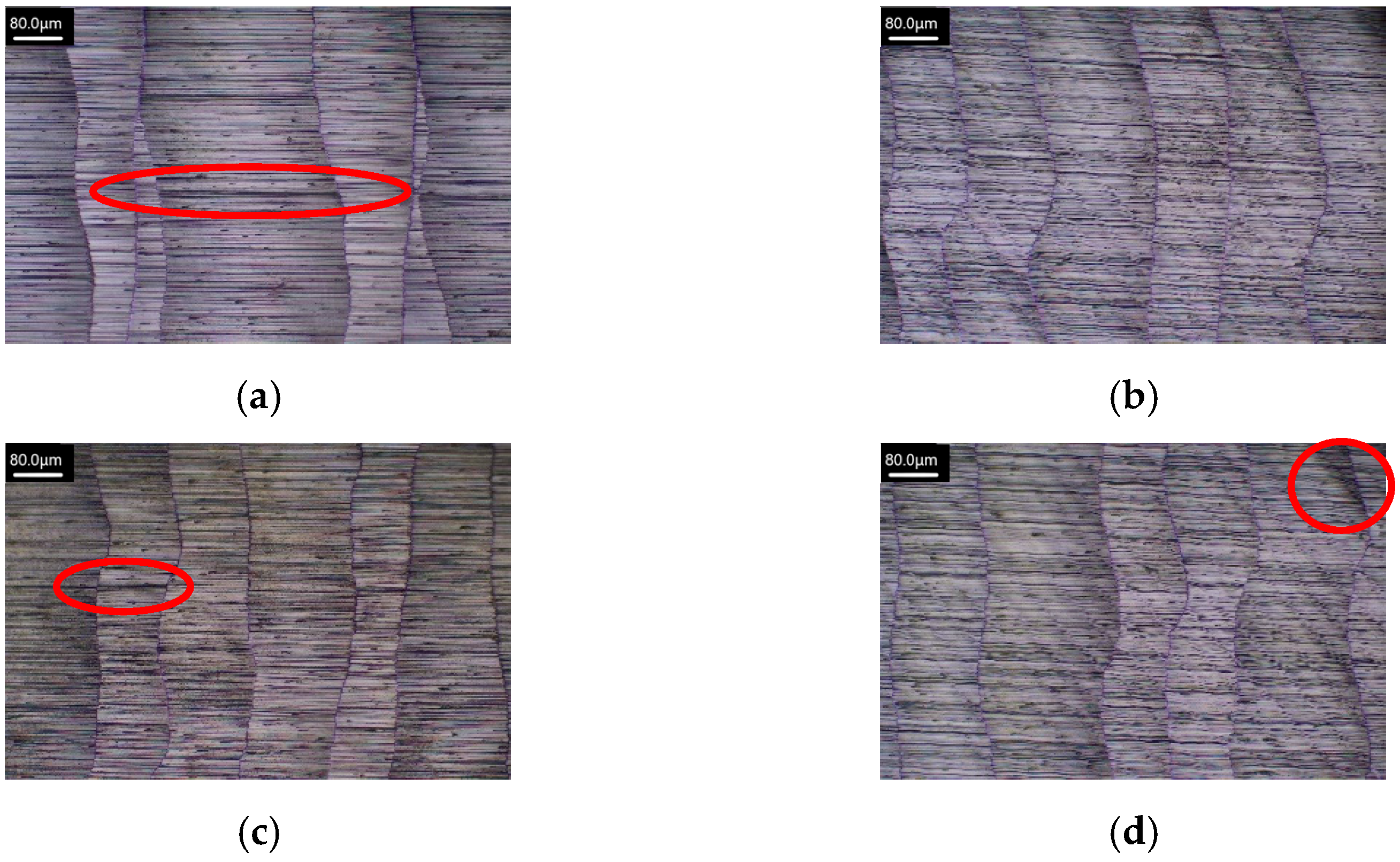
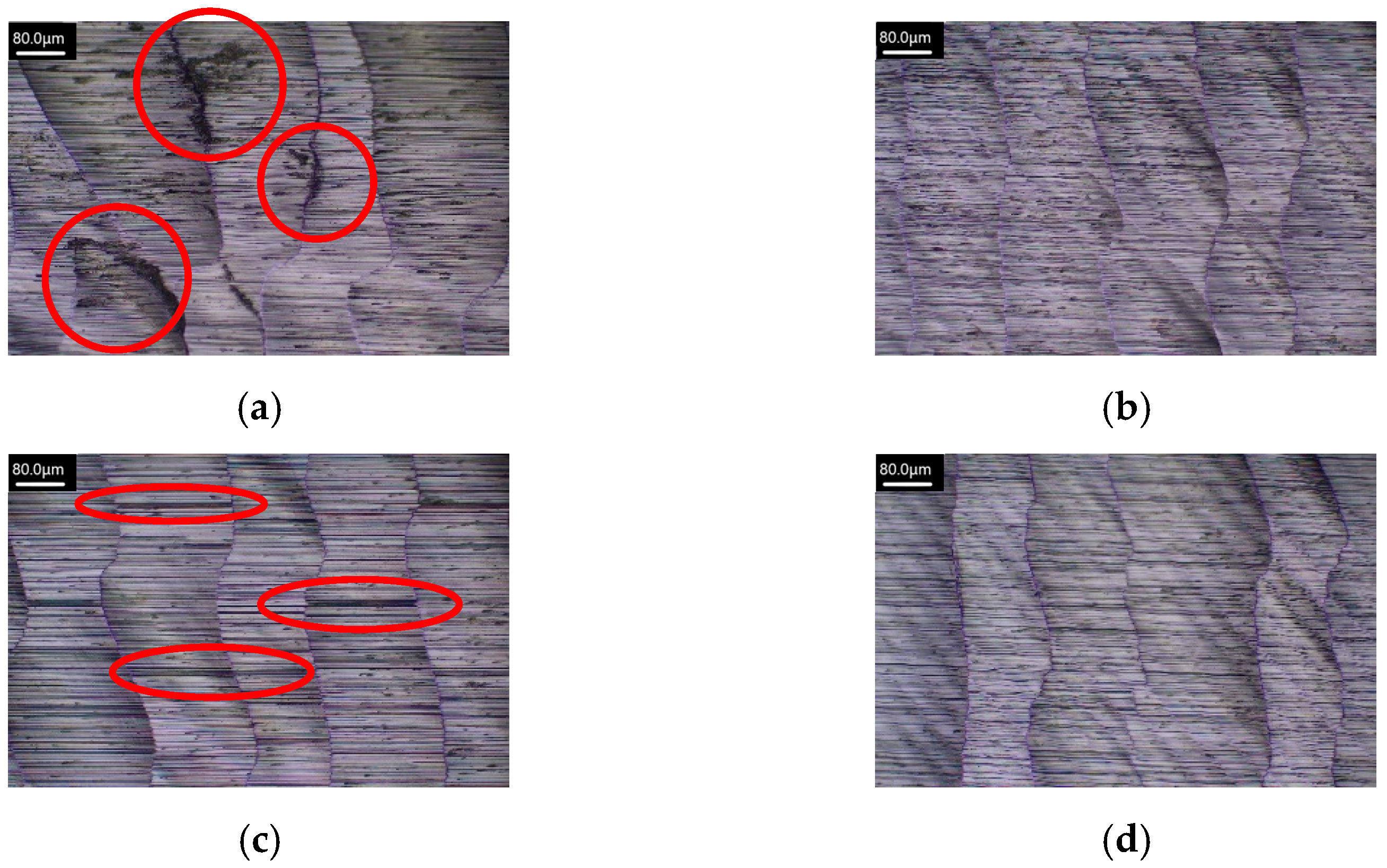
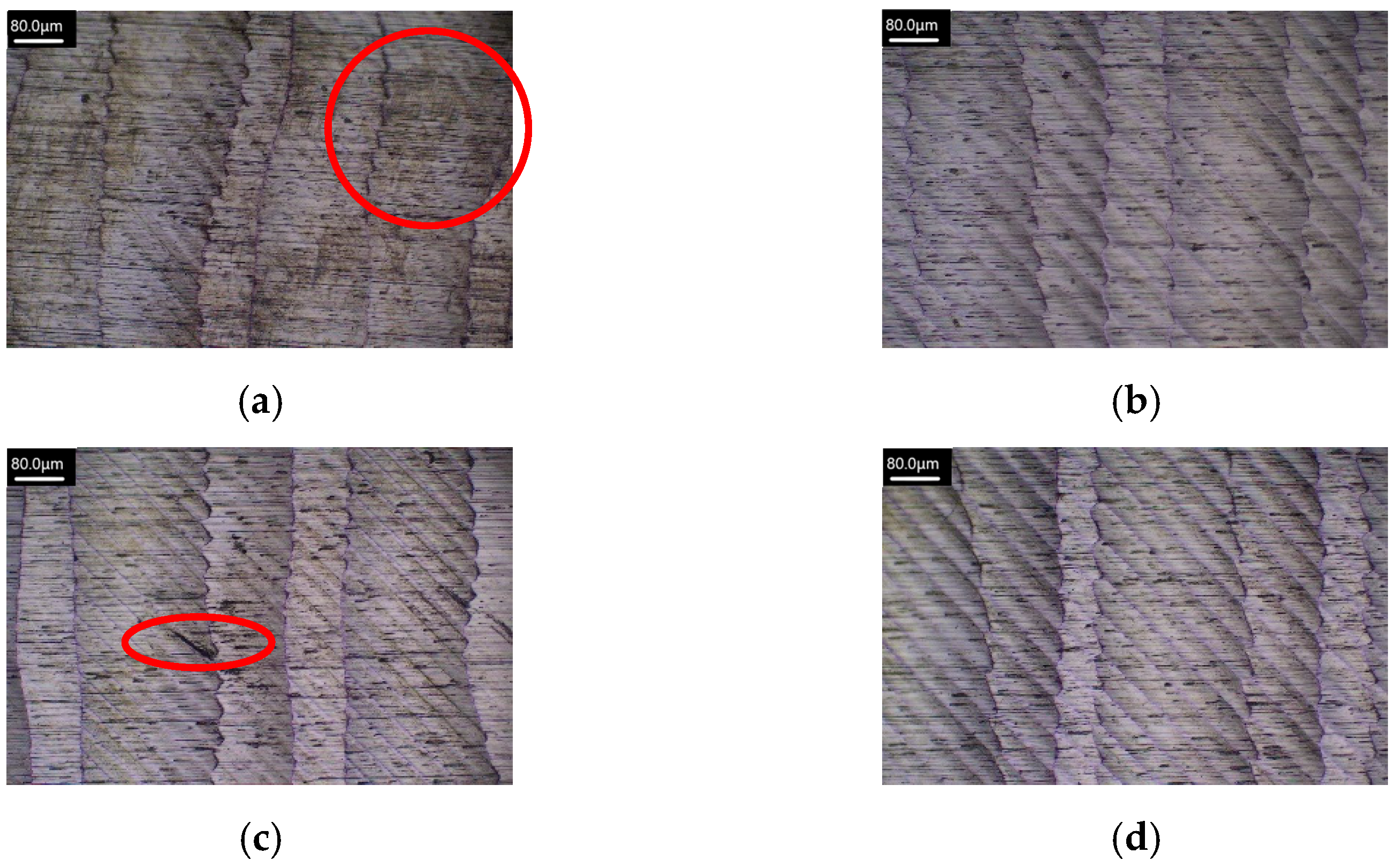
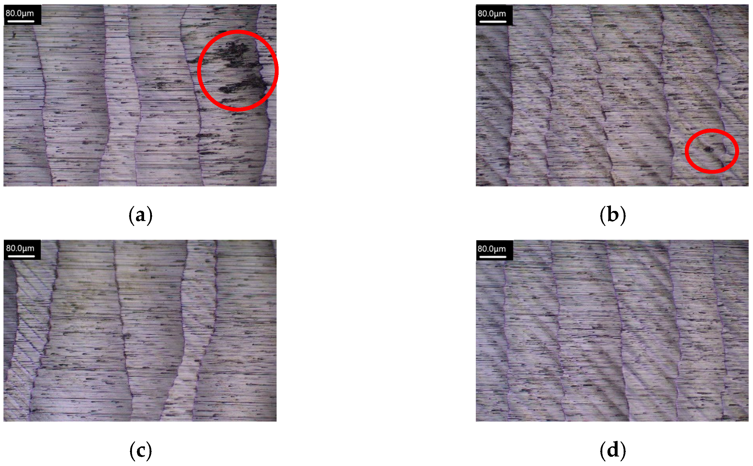
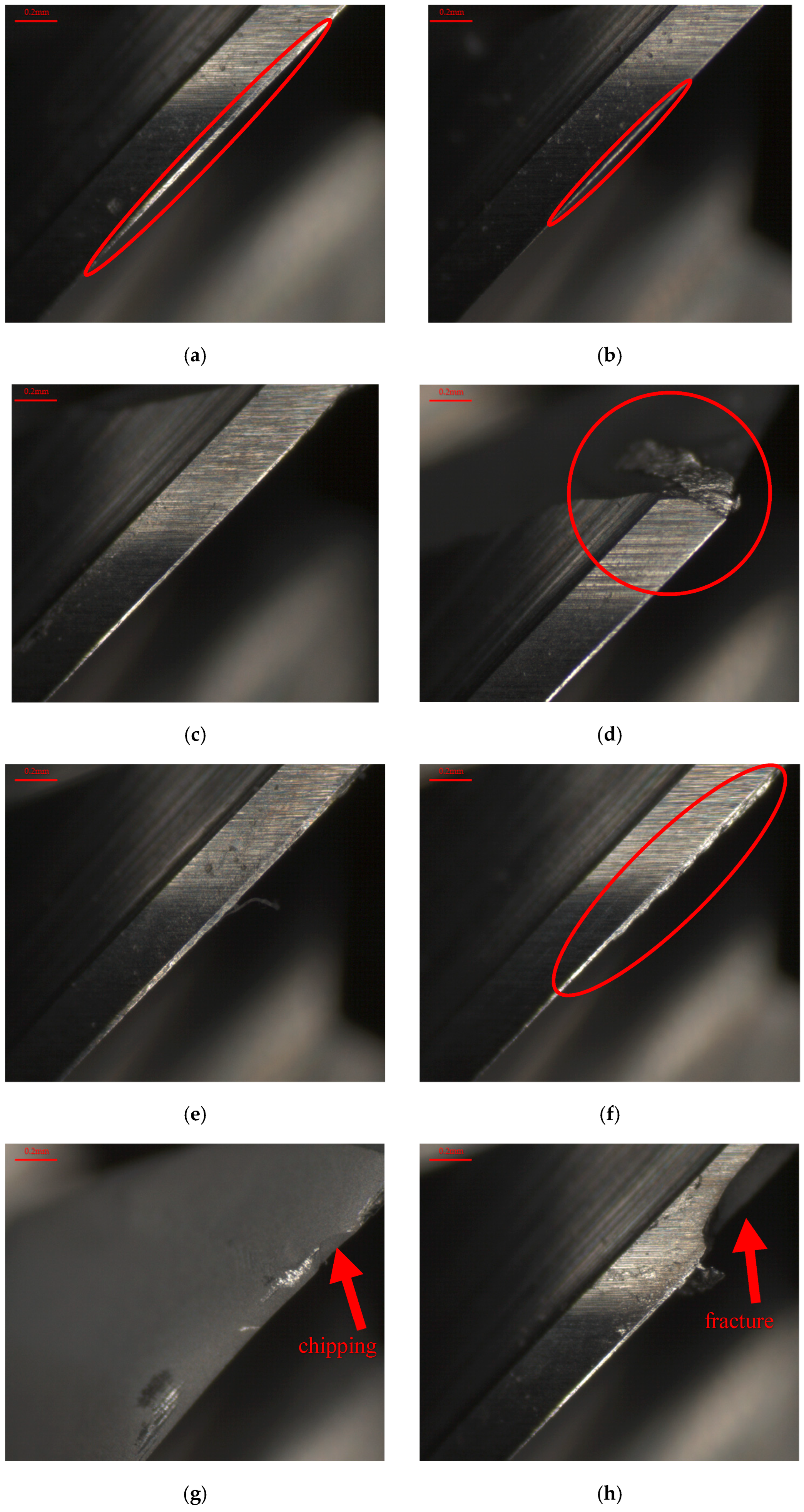
FeCoNiCrMn is a type of HEA characterized by high strength, hardness, and excellent corrosion resistance. It is composed of multiple elements in equal molar ratios, where chromium and nickel contribute to its superior corrosion resistance, cobalt and iron provide mechanical strength, and manganese gives ductility and toughness enhancements. These elements form a complex multi-phase microstructure, allowing the material to maintain stable performance even in high-temperature and harsh environments. Due to the interactions between the elements and the effects of varying elemental ratios, the alloy’s high hardness and strength increase the cutting forces during machining processes, leading to accelerated cutting tool wear. Additionally, the presence of multiple phases can cause interface disruption during the cutting process, resulting in machining defects such as surface quality and dimensional accuracy reductions. The interaction and matching properties of different elements in HEAs with cutting tools are not the same during the cutting process. Under the actions of cutting loading, the alloy may experience defects such as internal cracking, surface spalling, and material deformation.
Richter et al. [1] investigated the machinability of CoCrFeMnNi HEA and CoCrNi medium-entropy alloy (MEA). Ultrasonic-assisted milling (USAM) was performed in dry conditions using a physical vapor deposition (PVD) AlSiTiN-coated tungsten carbide end mill using different milling process parameters for these alloy materials. The effects of varying cutting speed, spindle speed, and feed rate on cutting force, tool wear, and surface roughness were examined. It was found that when machining CoCrFeMnNi HEA, the cutting force could be reduced to 35 N by decreasing the feed rate and increasing the cutting speed. The cutting force was further reduced by 2 N through ultrasonic-assisted milling, and surface integrity was improved, leading to a reduction in tensile residual stresses and defect density near the machined surface. Additionally, the size of the subsurface deformation-affected zone was reduced by USAM. Furthermore, the lowest surface roughness was achieved at a cutting speed of 50–70 m/min. When machining CoCrNi MEA, severe tool wear was observed during the experiment, resulting in a significant increase in cutting force. Moreover, severe surface defects were found on the CoCrNi MEA, including breakouts at the surface and the initiation of high tensile residual stresses. Richter et al. [2] investigated the machinability and surface integrity of CoCrFeNi MEA using USAM. A full-factorial experiment was designed to perform milling experiments at different cutting speeds and feed rates. A PVD AlSiTiN-coated tungsten carbide end mill was utilized in USAM experiments, and measurements of cutting force, surface morphology, surface roughness, and residual stresses were also carried out. It was found that under the conditions of low feed rate, high cutting speed, and the use of USAM, the cutting force was reduced. Tear/groove defects were observed on the workpiece surface in both conventional milling and USAM. Therefore, no significant effect of USAM or cutting speed on surface roughness was observed. A noticeable reduction in surface roughness was only found when the feed rate was decreased. Regarding residual stresses, higher tensile residual stresses were generated on the surface during conventional milling as the feed rate and cutting speed were increased. Compared to conventional milling, USAM exhibited lower tensile residual stresses at higher feed rates and cutting speeds. Richter et al. [3] investigated the surface integrity of CoCrFeMnNi HEA under conventional milling and USAM conditions. A full-factorial experiment was designed to perform milling experiments at different cutting speeds and feed rates. USAM was conducted using a PVD TiAlSiN-coated tungsten carbide end mill, and measurements of cutting force, surface integrity, surface roughness, and residual stresses were carried out. It was found that as the feed rate decreased, the cutting force was reduced by 38%. When the cutting speed was increased from 40 to 110 m/min, a 28% reduction in cutting force was observed. Through USAM, the average cutting force was further reduced by 5%. Regarding surface integrity, a significant improvement in the surface integrity of CoCrFeMnNi HEA was observed with USAM compared to conventional milling. This was confirmed by a reduction in microdefects on the machined surface and a decrease in tensile residual stresses at or below the surface. Liang et al. [
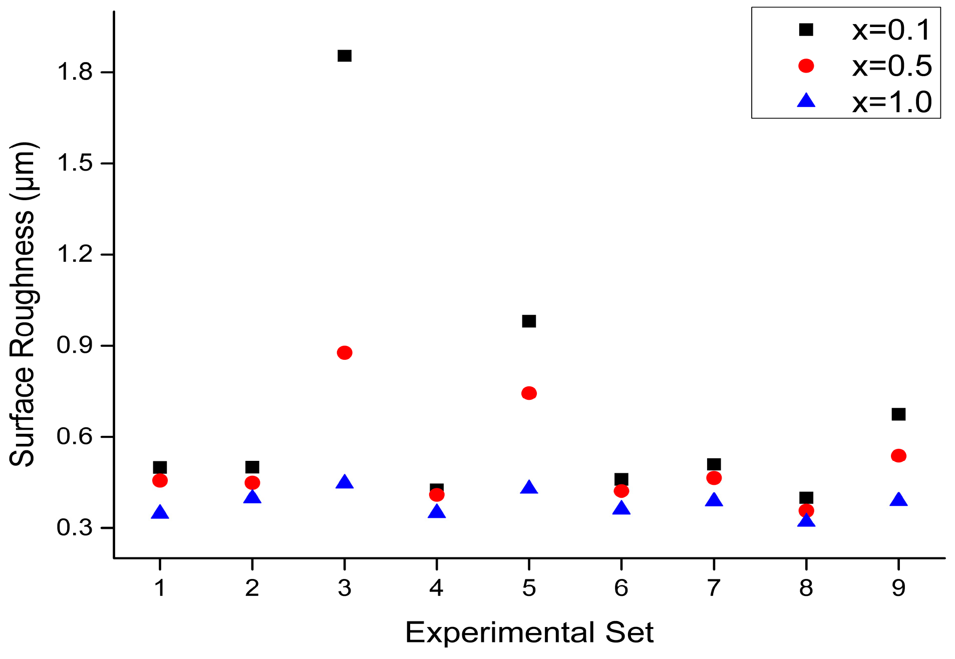
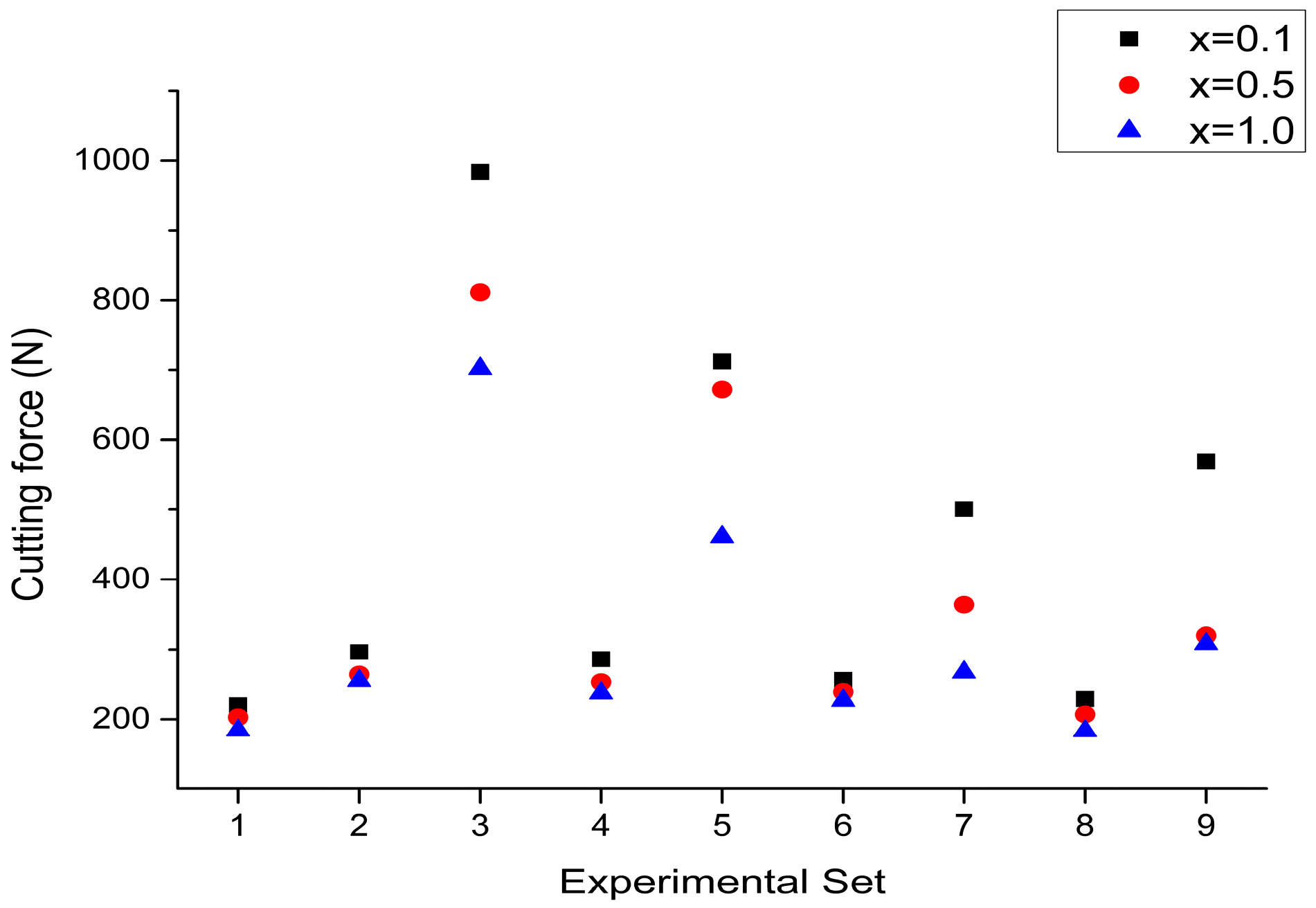
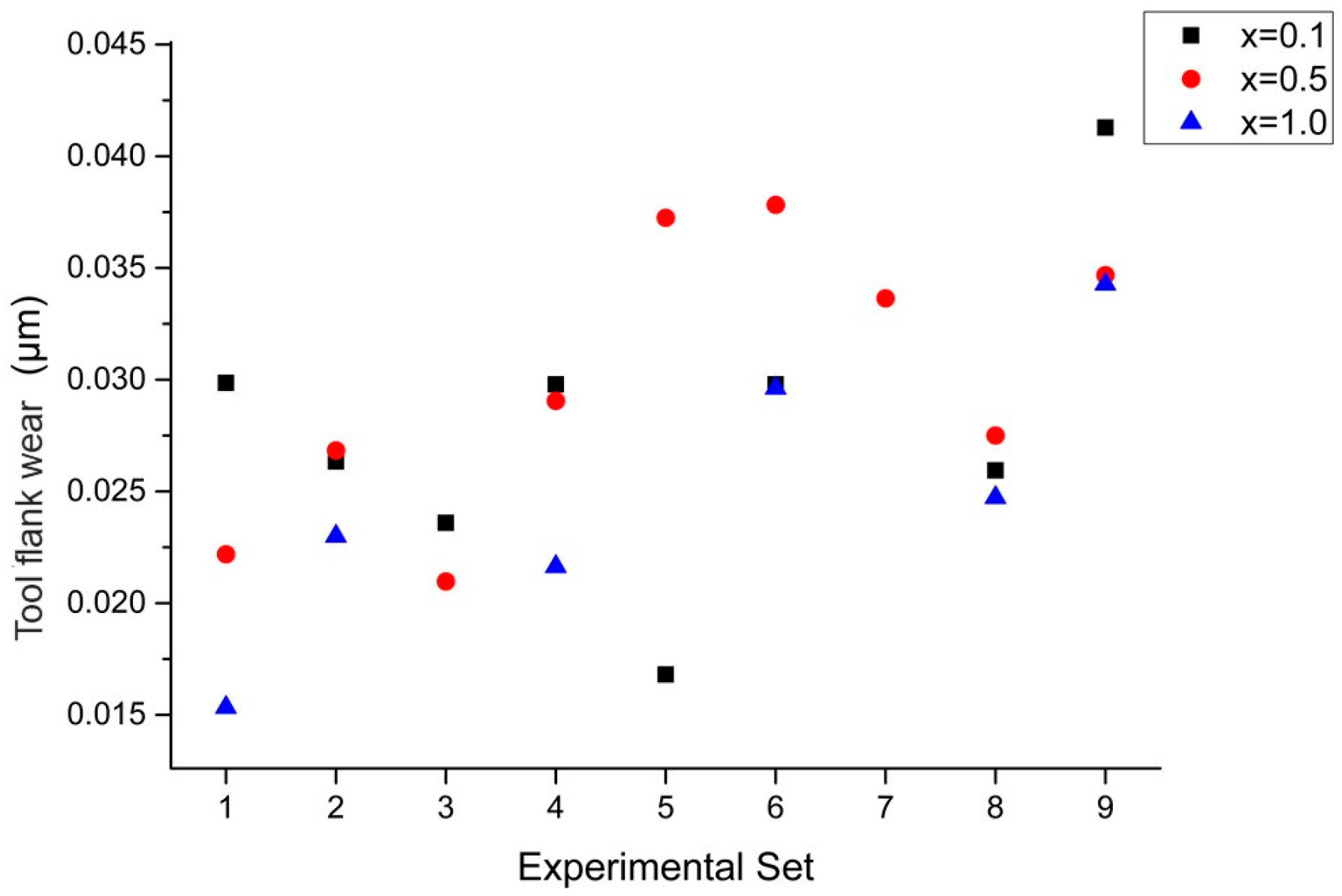
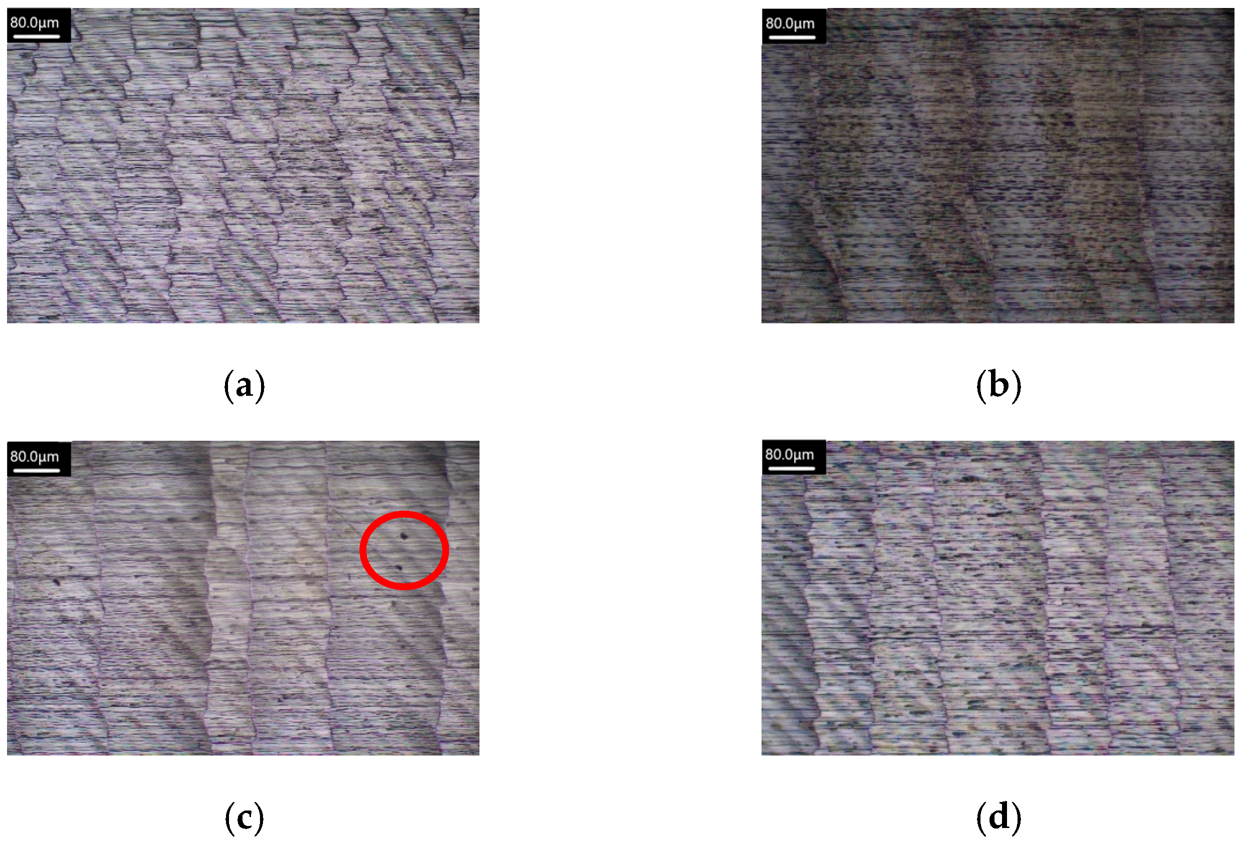
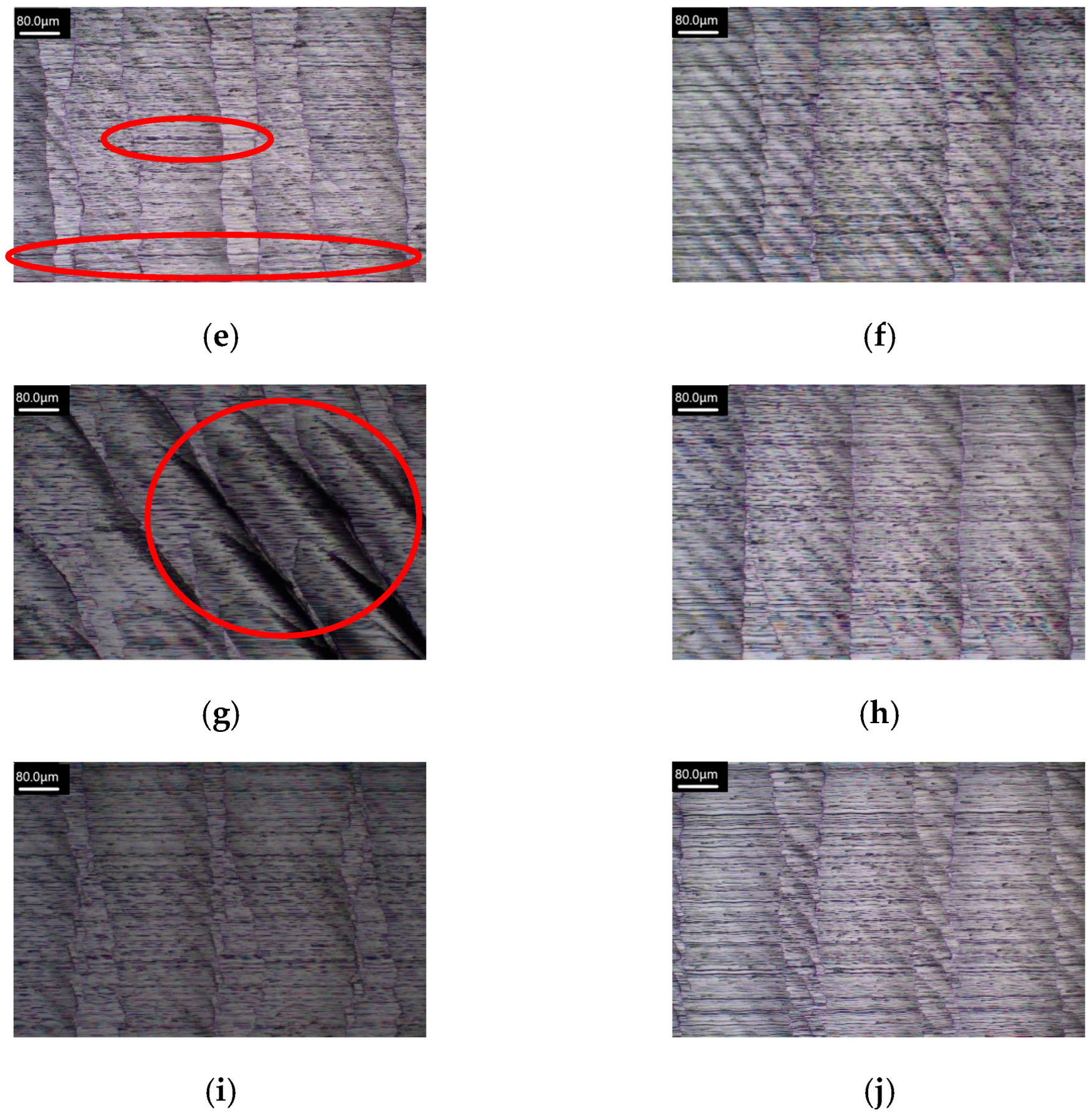
4] conducted micro-milling experiments on FeCoNiCrAlx HEAs using an ultra-precision milling machine to investigate the effects of different aluminum contents (x = 0.1, 0.5, 1) on tool wear, surface quality, and cutting force. First, the machining parameters and tool parameters were kept constant, and then experiments were carried out with varying aluminum content. Finally, the machining characteristics obtained with different aluminum contents were measured and observed. The results showed that the combined effects of adhesive wear, mechanical shock damage, abrasive wear, and oxidative wear were the main mechanisms of tool wear, while the influence of diffusive wear was relatively insignificant. As the aluminum content was increased, the cutting force became larger, leading to a higher cutting temperature and more severe tool wear. Specifically, when x = 1, tool wear was increased by approximately 53.2% compared to x = 0.1. Additionally, when the micro-milling distance reached 120 mm, surface roughness was decreased by about 20%. Liang et al. [5] conducted an experimental study on the machining characteristics of FeCoNiCrAlx HEA for micro-milling. First, FeCoNiCrAlx HEA was prepared using vacuum arc melting, with the aluminum content (x = 0.1, 0.5, 1) modified to induce changes in hardness. Then, micro-milling experiments were performed by varying process parameters such as spindle speed, feed rate, and cutting depth. Finally, the microstructure was observed and measured using an electron microscope. The results showed that as the aluminum content was increased, the crystal structure transformed from FCC to FCC + BCC when x = 1. Compared to x = 0.1, the increase in hardness led to a 229.8% rise in cutting force, a 46.8% increase in surface roughness, and more severe tool wear. Based on the experimental results, an aluminum content of 0.1 was found to be more suitable for micro-milling. Zhang et al. [6] used a finite element method based on the Johnson–Cook constitutive model to conduct a numerical simulation of a single-factor experiment in which a PVD-coated cemented carbide tool was used to investigate the effect of process parameters on the cutting force, cutting temperature, and residual stress of FeCoCrNiAl0.6 micro-cutting. The process parameters included cutting speed, cutting depth, and feed rate. The simulation results showed that as cutting depth and feed rate were increased, the three-dimensional cutting force gradually rose, exhibiting a positive correlation with both cutting depth and feed rate. Additionally, an increase in cutting speed caused small fluctuations in cutting force, which remained relatively stable. Simultaneously, during the cutting process, the maximum temperatures on the tool surface and chip surface gradually increased with increasing cutting depth, cutting speed, and feed rate, showing a positive correlation with cutting temperature. At different cutting depths, the residual stress on the workpiece surface showed a changing trend of first decreasing and then increasing. Additionally, as feed rate was increased, the absolute value of the maximum residual stress on the workpiece surface also increased. Zhang et al. [7] investigated the effects of different Al contents, CoCrFeNi (Al0), CoCrFeNiAl0.6 (Al0.6), and CoCrFeNiAl (Al1), on the micro-milling mechanism of CoCrFeNiAlx HEAs. A 3D micro-milling model was established using ABAQUS finite element software, and a numerical simulation of a single-factor experiment was conducted using a 10X tungsten steel end milling cutter to explore the law of changes in the temperature field, milling force, residual stress, and surface roughness for different Al contents. The process parameters included milling speed, milling depth, and feed rate. The simulation results showed that Al1 chips are mostly shaped like long strips, Al0.6 chips are mostly granular, and Al0 chips are mostly shaped like long flakes. At the same milling speed, the milling temperature of the workpieces with different Al contents followed the order: Al1 > Al0 > Al0.6. As milling speed was increased, the milling force in the y and z directions remained almost the same for workpieces with different Al contents. The milling forces of Al1 and Al0 were changed very little in the x direction, while those for Al0.6 tended to increase first and then decrease. With increasing milling speed and milling depth, the residual stress of the workpieces with different Al contents followed the order: Al1 > Al0.6 > Al0. Among all workpieces, Al0.6 exhibited the lowest surface roughness. Zhao et al. [8] conducted a study on tool wear and machining quality of AlCoCrFeNi2.1 EHEA and proposed a plastic flow characterization method marked by the B2 phase. Cutting temperature and cutting force were measured to explain variations in tool wear and machining quality. Finally, surface roughness and surface morphology changes were analyzed by varying cutting speed and feed rate. The results showed that as cutting speed and feed rate were increased, both cutting temperature and cutting force rose. With the material removal rate unchanged, an increase in cutting speed and feed rate led to a greater flank wear width. When the cutting speed was below 80 m/min, abrasive wear was dominant, whereas at 110 m/min, adhesive wear and coating delamination occurred. When the cutting speed reached 140 m/min or the feed rate reached 0.14 mm/tooth, vibrations were generated during the machining process which potentially caused a sharp deterioration in surface morphology. Li et al. [9] conducted micro-milling experiments on FeCoNiCrMn HEA and established a minimum cutting thickness prediction model based on the effective front angle of the tool. Milling parameters were substituted into the prediction model to calculate the minimum cutting thickness of FeCoNiCrMn HEA, and the accuracy of the prediction model was verified through the analysis of micro-milling force and specific cutting energy. The results showed that when the cutting edge radius of the milling tool was 5 μm, the predicted minimum cutting thickness of the HEA was calculated to be 1.367 μm. The variation trends of micro-milling force and specific cutting energy determined that the minimum cutting thickness range was between 1 μm and 1.5 μm, thereby confirming the accuracy of the minimum cutting thickness prediction model. Haidong et al. [10] investigated the cutting performance and chip morphology of WNbMoTaZr0.5 refractory HEA (RHEA). Turning experiments were conducted using PVD-Al2O3 + TiCN-coated tungsten carbide tools on three different alloys: WNbMoTaZr0.5 RHEA, Cr12MoV die steel, and GCr15 bearing steel. The study analyzed the effects of cutting speed, depth of cut, feed rate, and tool nose radius on cutting force, surface quality, and chip morphology under dry conditions. The results showed that WNbMoTaZr0.5 RHEA demonstrated excellent thermal stability and high hardness compared to the other two alloys. The cutting force and surface roughness were increased with cutting speed, but the rate of change was decreased. Additionally, under the same cutting conditions, WNbMoTaZr0.5 exhibited higher cutting forces than Cr12MoV and GCr15, but with lower and more stable surface roughness, suggesting that increasing the depth of cut could improve machining efficiency. Furthermore, when the depth of cut was increased, the machined surface exhibited scale-like patterns and groove marks, which became more pronounced at higher cutting speeds. At a high cutting speed of 70 m/min, the light emission phenomenon was observed. The study also found that chip thickness and width were influenced by depth of cut, feed rate, and tool nose radius, with burn marks appearing on the chip’s back surface. Moreover, the primary tool wear mechanism for machining WNbMoTaZr0.5 RHEA was adhesive wear, which was decreased as the tool nose radius was increased. Adhesive wear decreased progressively. Wang et al. [11] conducted milling experiments on AlCoCrFeNi HEA using a CNC milling machine. A four-factor and four-level orthogonal experiment was performed, and the trends and primary and secondary order of the influence of milling parameters on milling force were analyzed using extreme difference analysis and intuitive analysis, respectively. The process parameters included spindle speed, milling depth, milling width, and feed rate. The results showed that as spindle speed was increased, milling force gradually increased. With an increase in feed rate, milling force first increased, then decreased, and then increased again. As milling depth was increased, milling force increased and then decreased. When milling width was increased, milling force first decreased and then increased. Through extreme difference analysis, the trends and the degree of influence of milling parameters on the milling forces in three directions can be obtained. The factors that have the greatest influence on the milling force are the spindle speed, followed by milling depth and feed rate, and finally the milling width. Kaushik et al. [12] investigated the face milling performance of HEAs with different elemental compositions and varying process parameters. Milling experiments were conducted using PVD-AlSiTiN-coated tungsten carbide tools of different diameters, analyzing the effects of tool diameter, cutting speed, feed rate, and depth of cut on several response parameters, including cutting force, cutting torque, material removal rate, tool wear, and surface morphology. The results indicated that by increasing tool diameter and cutting speed, the surface roughness may be effectively reduced, while different HEA compositions had varying effects on machining responses. An increase in tool diameter led to a rise in chip thickness, significantly affecting the feed force and radial force. Among the tested HEA samples, Cr20Mn10Fe20Co30Ni20 exhibited the best performance in terms of average surface roughness. Further experiments revealed that the interactions between cutting speed, axial depth, and feed rate played a crucial role in machining. The second-level cutting speed and depth of cut, combined with the third-level feed rate, were identified as the optimal conditions. Microstructural changes contributed to the formation of surface defects, which could be mitigated by employing low feed rates and high cutting speeds. Ultimately, the surface roughness of the HEA samples improved after machining, with CrMnFeCoNi showing a 1.547% increase in microhardness. Kao et al. [13] investigated the mechanical properties, tribological properties, and corrosion resistance of AlCrNbSiTi HEA nitride coatings with different nitrogen flow rates. They further applied these coatings in the milling of the nickel-based alloy Inconel 718. Using reactive RF magnetron sputtering, HEA nitride coatings were deposited on tungsten carbide tools within a nitrogen flow range of 0–20 cm3/min. Various measurement instruments were used to analyze the coatings’ chemical composition, chemical bonding characteristics, and crystalline structure. Additionally, the hardness, elastic modulus, adhesion strength, friction coefficient, and wear resistance of the coatings were evaluated. Corrosion resistance was assessed through potential polarization testing. Finally, face milling experiments on Inconel 718 were conducted using milling to analyze the effect of the coatings on tool life. The results indicated that all coatings exhibited an amorphous structure. As nitrogen flow was increased, coating hardness also increased, reaching its highest value at a nitrogen flow of 15 cm3/min. Under these conditions, the coating demonstrated the best wear resistance, the lowest friction coefficient, and excellent corrosion resistance. Further milling experiments revealed that tool wear may be effectively reduced during the machining of Inconel 718 when the coating with a nitrogen flow of 15 cm3/min. After a milling distance of 18 m, the tool wear depth was only 154.4 μm, showing significant improvement compared to uncoated tools and tools coated without nitrogen. Litwa et al. [14] investigated the manufacturing quality of CrMnFeCoNi HEA produced using laser powder bed fusion and further applied it to milling experiments. They explored the effects of process parameters on cutting force, surface roughness, and tool wear. Using uncoated tungsten carbide tools, a milling experiment was performed on the HEA while varying process parameters such as feed rate, cutting speed, and depth of cut to analyze their influence on cutting force, surface roughness, and tool wear. A comparative analysis with 304 stainless steel was also conducted. The results showed that the HEA exhibited good homogeneity and machinability. Compared to 304 stainless steel, the HEA required lower cutting forces, experienced less tool wear, and achieved better surface roughness. Additionally, the cutting force of the HEA was increased with increasing depth of cut and feed rate, while the most stable performance was observed at the lowest cutting speed. Tool wear did not show significant variation, and surface roughness was reduced by 61.3% compared to 304 stainless steel. Under the same cutting conditions, the HEA demonstrated reduced tool wear and excellent homogeneity, with tool wear remaining below 50 μm. Liborius et al. [15] conducted an end-face turning experiment on CoCrFeNi HEA to investigate the effects of different cutting speeds and tool materials on tool wear, surface roughness, and cutting force. The specimens were premachined by boring and internal turning to ensure constant cutting speeds in face cutting process. The HEA was then subjected to end-face turning using different tools (CBN, PCD diamond, CVD diamond, and tungsten carbide) and cutting speeds. Finally, a laser microscope was used to observe and measure tool wear and surface roughness. The results indicated that a cutting speed of 300 m/min yielded the best results in terms of surface roughness and tool wear, with surface roughness consistently maintained within the range of 0.2~0.3 μm. Further detailed experimental tests could be conducted around the cutting speed of 300 m/min. Additionally, regardless of the cutting speed, CBN tools with higher boron nitride concentrations achieved better surface roughness and tool wear. Doan et al. [16] investigated the mechanical response of AlCrCuFeNi HEA during nanoscale cutting using diamond tools under the influence of different vibration frequencies, amplitude ratios, and phase angles. Molecular dynamics simulations were employed to compare conventional cutting with ultrasonic elliptical vibration-assisted cutting (UEVAC). A detailed analysis was conducted on the effects of varying vibration frequencies, amplitude ratios, and phase angles, with a focus on cutting forces and temperature changes. The results revealed that under UEVAC conditions, the temperature of the HEA was significantly higher than that in conventional cutting, and it was increased with higher vibration frequencies and lower amplitude ratios. Additionally, structural evolution analysis indicated that UEVAC generated more amorphous structures. In terms of dislocation and strain evolution, grain boundaries were found to play a critical role in deformation behavior. Although the maximum cutting force in UEVAC was greater, the average cutting force in conventional cutting was higher overall. Furthermore, under UEVAC conditions, the average cutting force decreased with increasing vibration frequency and amplitude ratio. Finally, when the vibration frequency reached 150 GHz, the amplitude ratio was 4, and the phase angle was 75°, a higher material removal rate and more intense plastic deformation were achieved, suggesting potential advantages for improving machining efficiency under these conditions. Clauß et al. [17] investigated the influence of process parameters on the surface properties of thermally sprayed AlCoCrFeNiTi coatings during turning. Experiments were conducted using CBN tools to perform external cylindrical turning on an aluminum alloy substrate coated with AlCoCrFeNiTi HEA. The effects of cutting speed and feed rate on surface properties were analyzed, while the cutting depth remained constant throughout the experiments. The results showed that increasing the cutting speed and reducing the feed rate led to a decrease in surface roughness parameters (Rz, Rvk) and valley void volume (Vvv), primarily due to a reduction in the proportion of pulled-out coating material. Additionally, compressive stresses were detected in the axial direction, with their absolute values decreasing as the cutting speed was increased. Constantin et al. [18] studied the effects of temperature and tool wear on HEA materials during the milling process, as well as the changes in hardness in the machining area. The cutting force, scrap aspect, and machined surface quality of HEA and 304 stainless steel using the same process parameters were compared. Further analysis was then conducted to assess the machinability of HEA. The experiments were conducted using a shank cutter and two PVTi-coated tungsten carbide inserts. The results showed that using PVTi-coated tungsten carbide end mills allows for effective machining of HEA without the need for coolant, while keeping tool wear within a steady-state wear region. In contrast, conventional cutting tool materials cannot be effectively applied to HEA, as excessive heat is generated during the machining process, severely limiting tool life. In terms of machinability, HEA performs approximately 59% better than stainless steel. Chemical analysis of the chip surface revealed that both HEA and 304 stainless steel exhibit a strong tendency to oxidize, and the analysis indicated that the material’s microstructure changes during the machining process. Microhardness measurements show that material inhomogeneity or the self-hardening effect caused by cutting forces is one of the reasons for chip fragmentation. Huang et al. [19] investigated the effects of spindle speed, feed rate, and cutting depth on surface roughness and morphology during ultra-precision cutting of Al80Li5Mg5Zn5Cu5 HEA using diamond tools and PCBN tools. Ultra-precision cutting experiments were conducted using Al80Li5Mg5Zn5Cu5 HEA rods, and the machined surface quality was collected using a white light interferometer. A microscope was used to observe the three-dimensional topography and the microstructural morphology of the HEA machined surface. Under scanning electron microscopy, two different crystalline phases were observed to form on the tool surface. The results show that when cutting with PCBN tools, greater compressive and frictional forces were generated between the tool and the HEA surface, promoting the refinement and diffusion of the eutectic phase, which the hardness of the finished surface was increased to 218 HV. In contrast, when using diamond tools, the hardness was decreased to 190 HV, primarily due to the influence of shear forces on the diamond tool. Shear force was also one of the reasons for the lower surface roughness observed. As the ultra-precision process parameters were increased, the surface roughness of Al80Li5Mg5Zn5Cu5 HEA was increased. The feed rate has the greatest influence on surface roughness, followed by cutting depth, while spindle speed has a smaller effect. Furthermore, when using diamond tools, the surface roughness (Ra) shows little variation, whereas when using PCBN tools, the Ra was increased significantly. Guo et al. [20] investigated the machinability of selective laser melting CoCrFeMnNi HEA through various processing methods, including milling, grinding, wire electrical discharge machining (wire EDM), and electropolishing (EP). Surface morphology, roughness, microhardness, residual stress, and subsurface quality were measured. Additionally, the effects of different machining processes on surface and subsurface quality were analyzed. The results show that milling and grinding may smooth the surface and enhance microhardness but introduce tool marks and compressed residual stresses due to microstructural deformation. Mechanical polishing, using low-pressure loose abrasives, creates an ultra-smooth surface without subsurface damage. Furthermore, wire EDM as a thermal processing method can flatten the surface but generates a heat melt layer, increasing tensile residual stress and surface microhardness. EP may smooth the surface, releases residual stresses, and removes subsurface damage, but it cannot achieve micron-level surface roughness from a very rough initial condition. Combining mechanical and electrical processes can yield better surface quality. In terms of elemental composition, the elements of CoCrFeMnNi HEA remain stable after mechanical and electrical treatments, but copper introduced by wire EDM alters its composition. There is an interrelation between microhardness, residual stress, and subsurface defects. Microstructural deformation leads to subsurface defects, which in turn increase microhardness and residual stress.
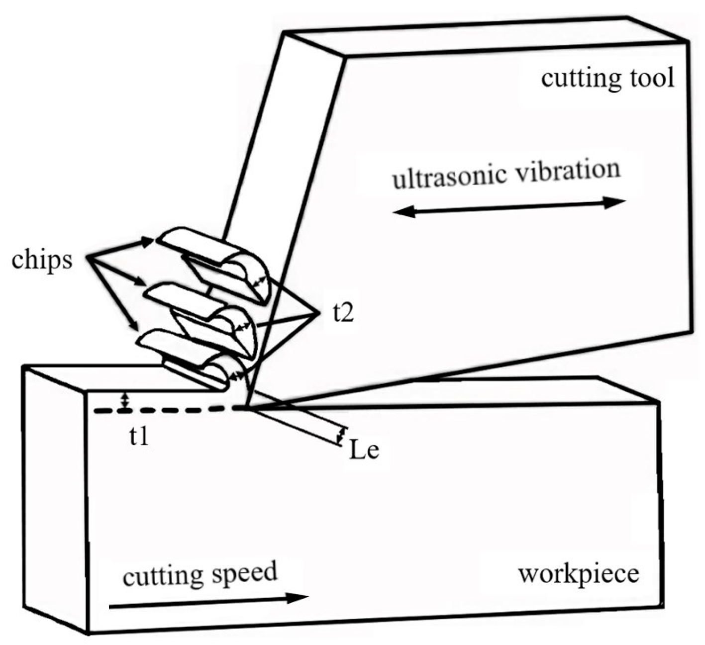
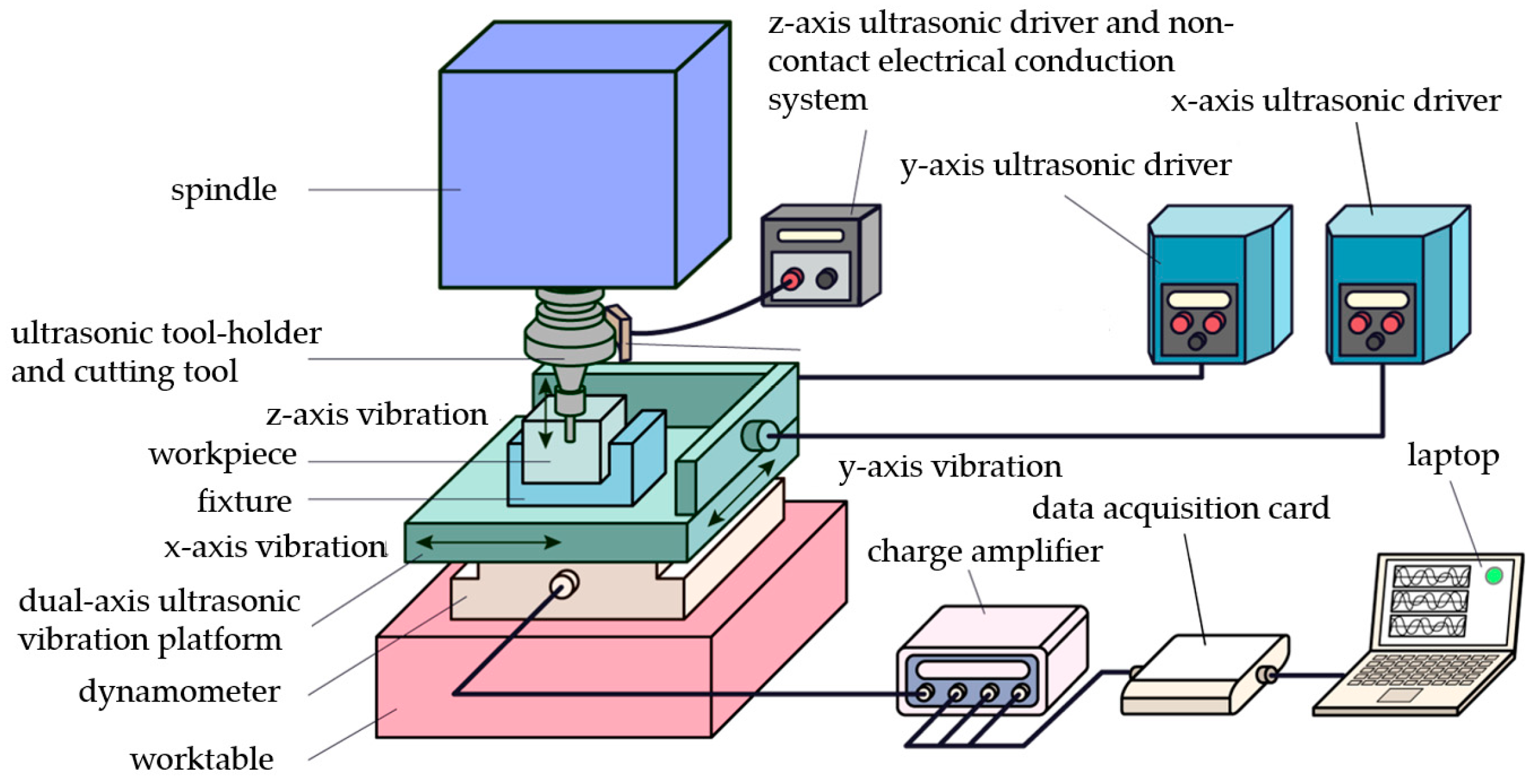
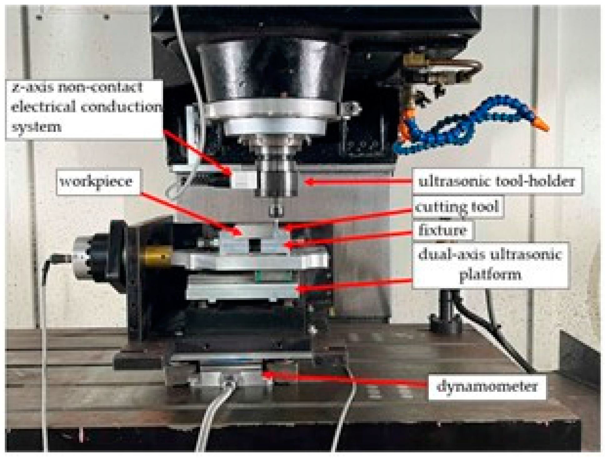
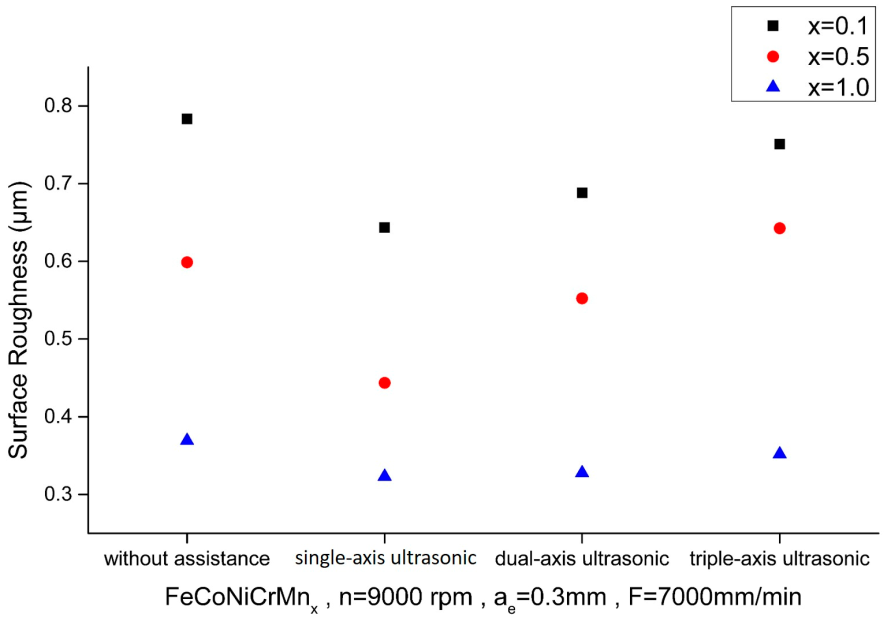
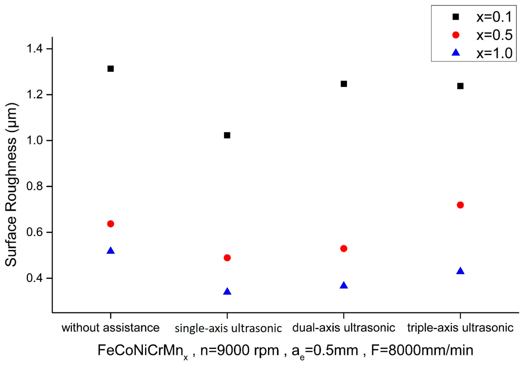
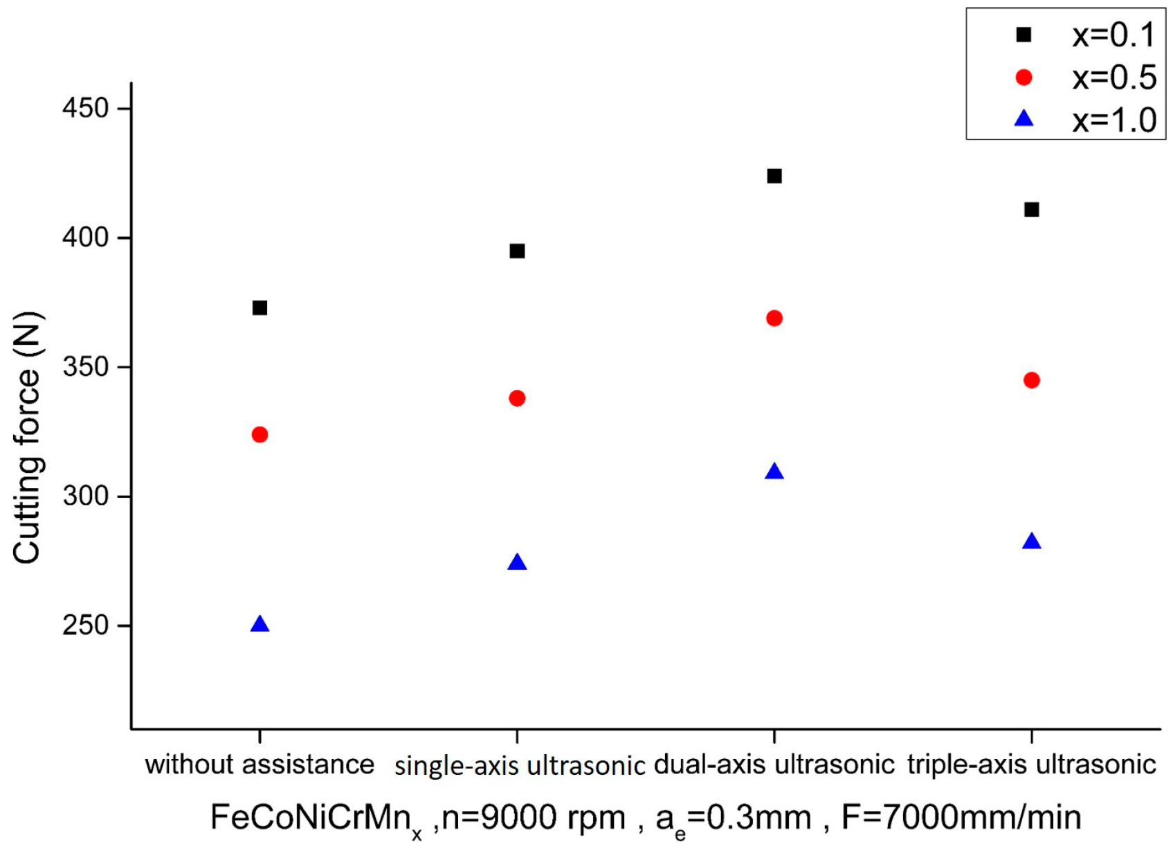
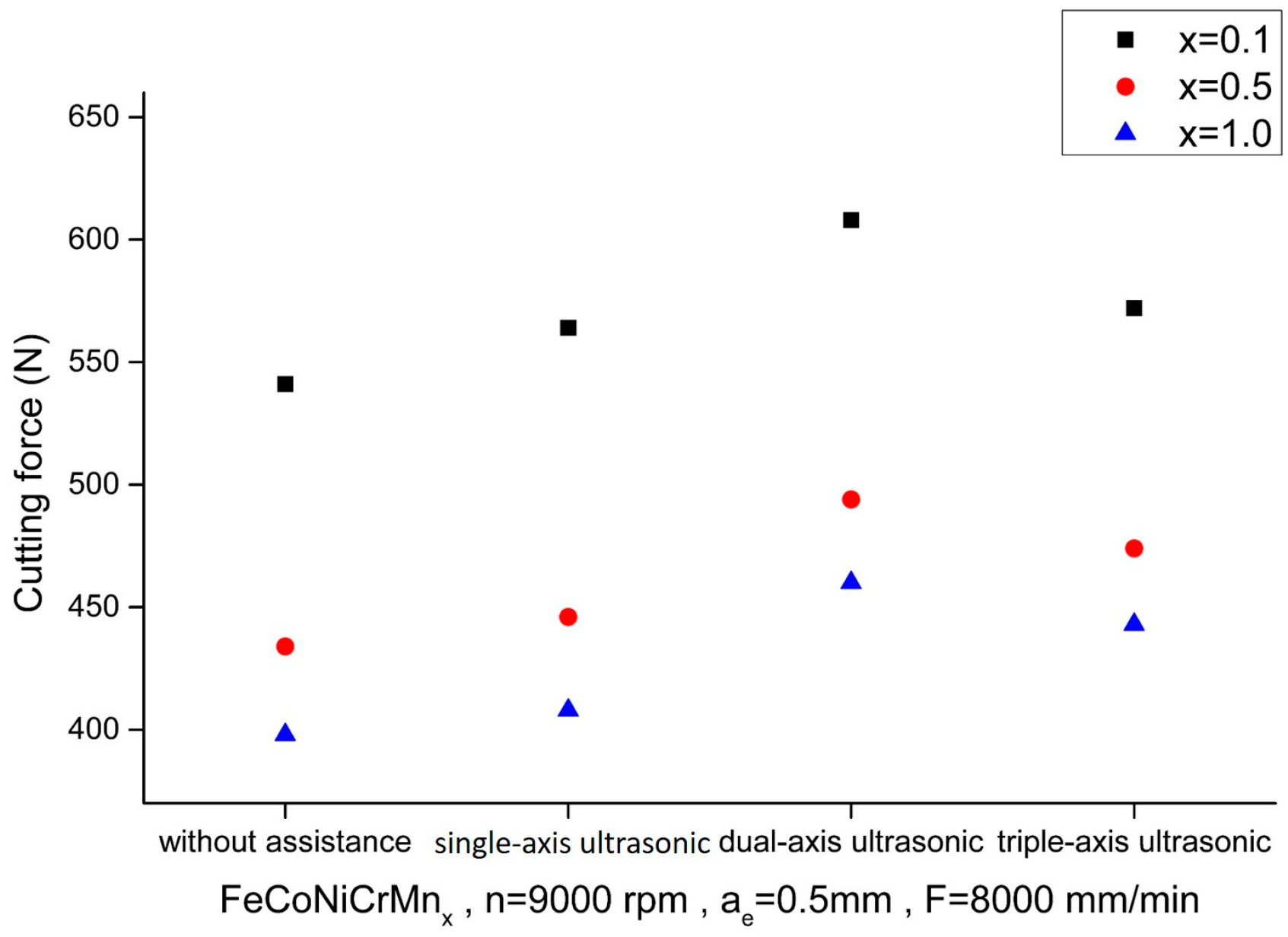
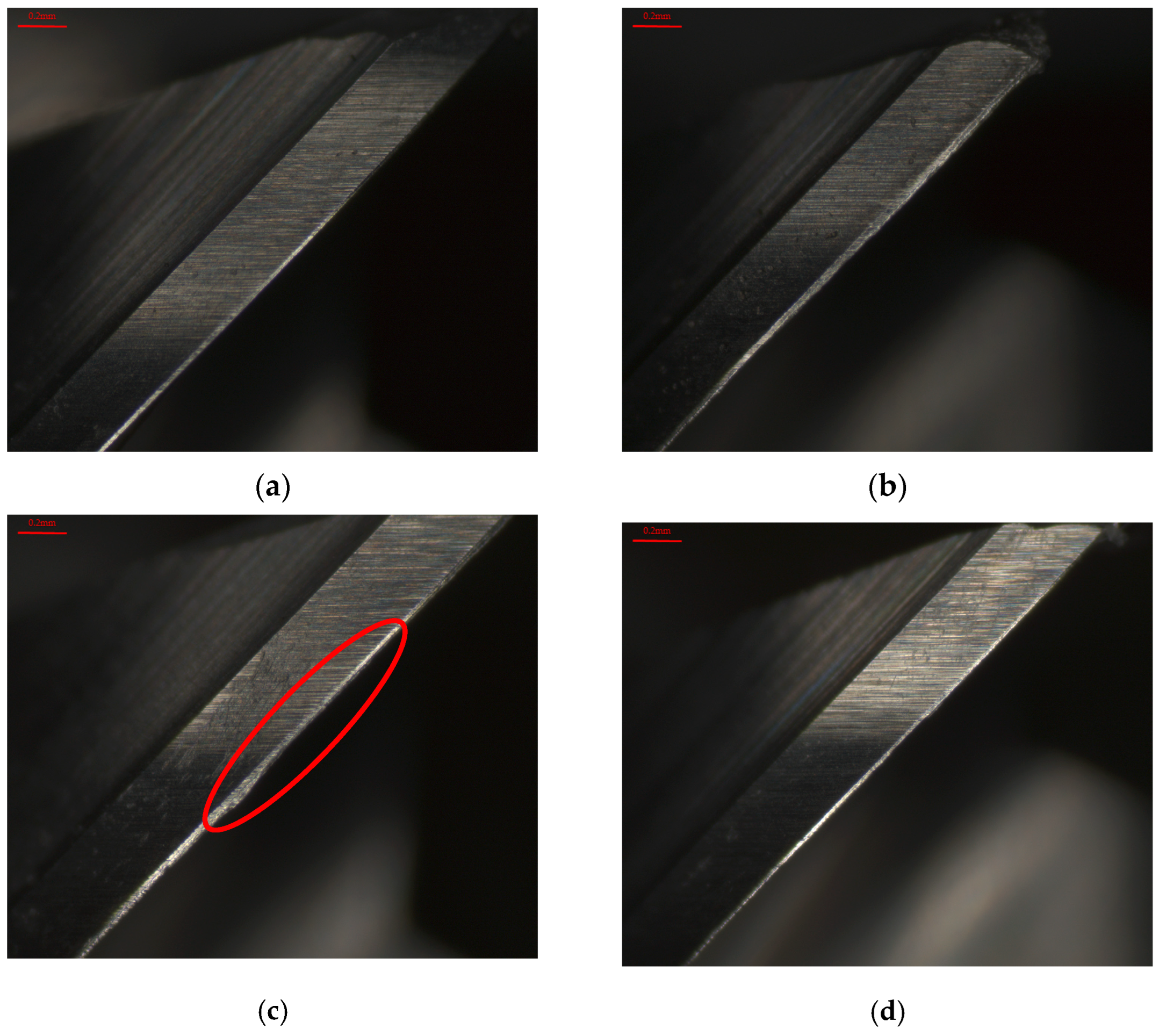
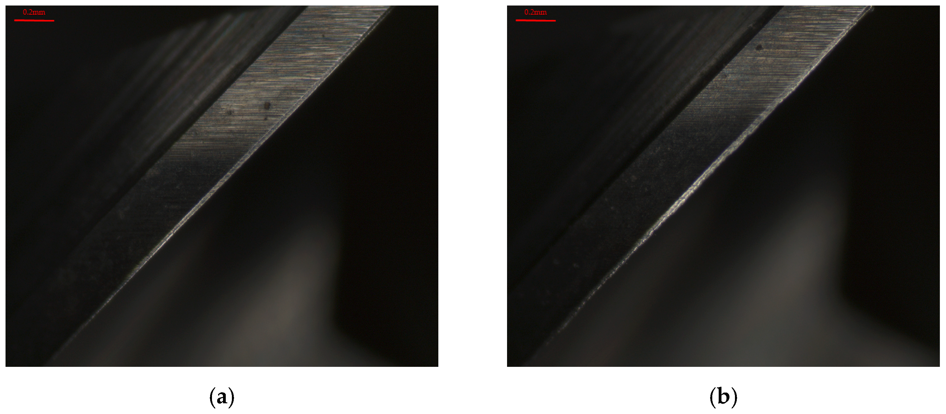
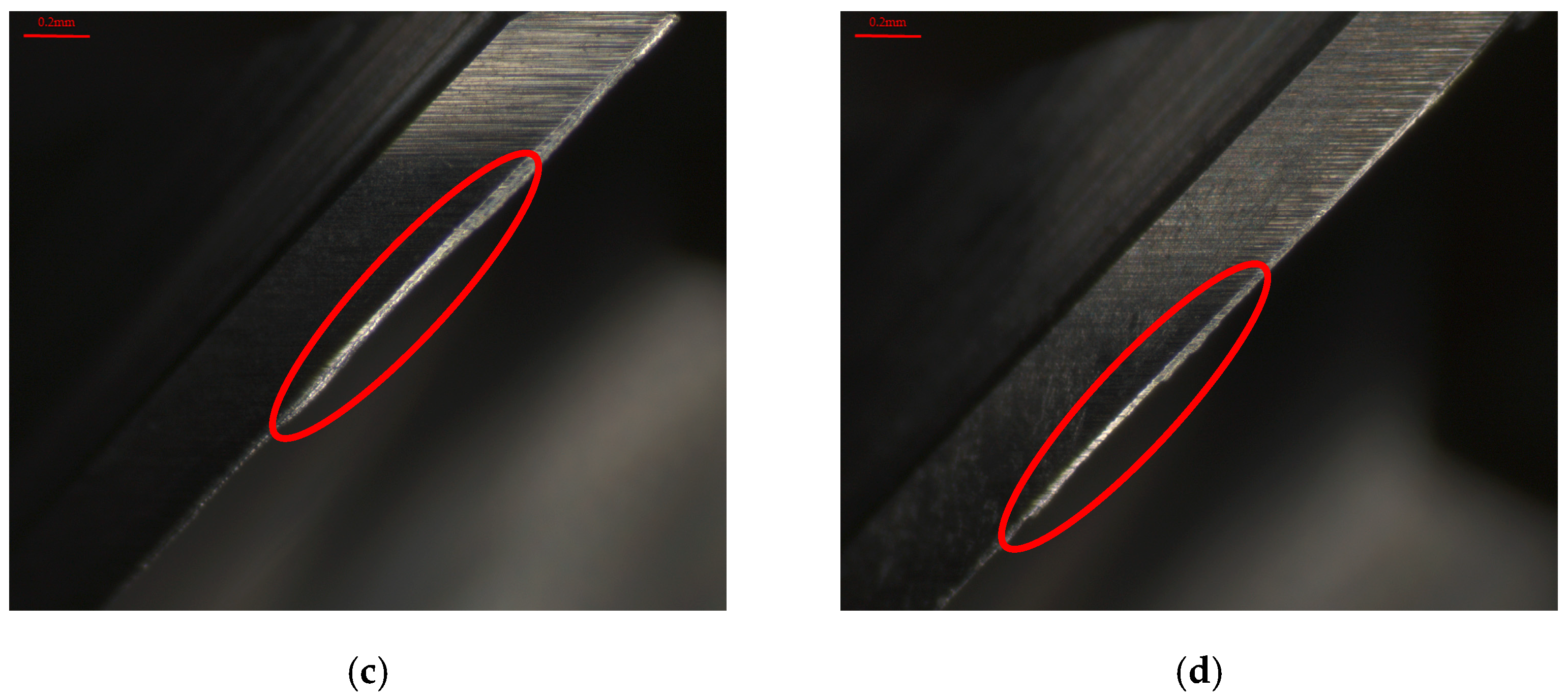
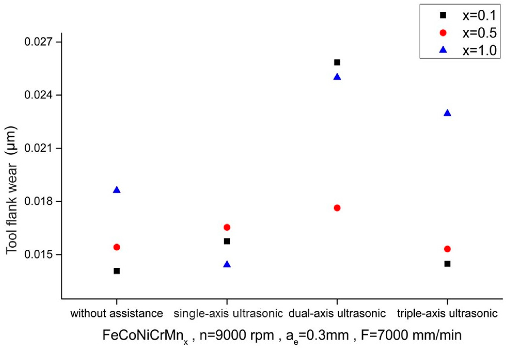
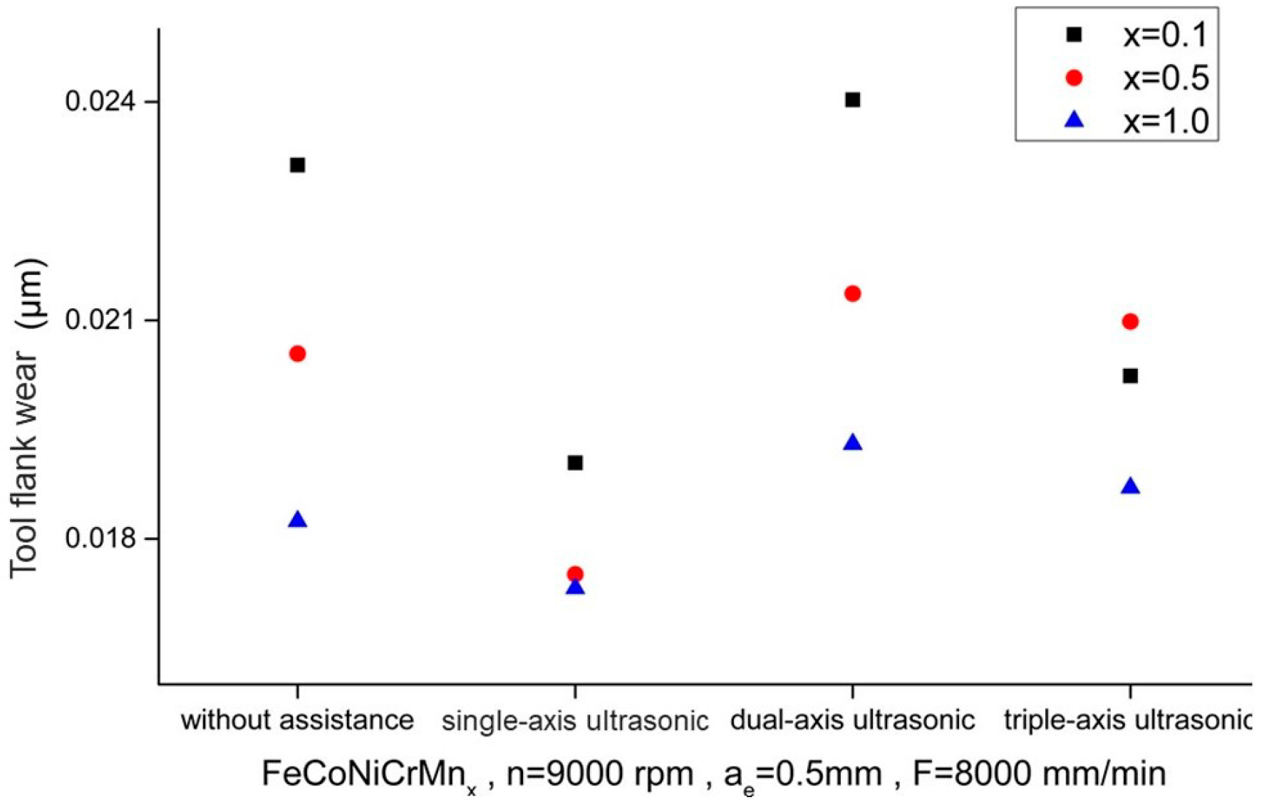
The literature review indicates that numerous micro-milling experiments have been conducted using workpieces prepared in the laboratory. Many of these studies employed single-axis ultrasonic systems or elliptical ultrasonic systems in assisted milling experiments. The effects of different process parameter combinations, various elemental compositions of HEAs or MEAs, and varying Al elemental ratios on cutting performance such as cutting force, surface roughness, and cutting tool wear have thus been investigated. HEAs are suitable for industrial applications that traditional alloys cannot meet. However, the properties of these alloys will be varied with different elemental compositions and various process parameters, making the machining processes highly complex and the cutting performance difficult to predict. Therefore, selecting appropriate cutting tools, processing parameters, and assisted methods, as well as understanding the potential changes brought by elemental variations, is essential for achieving high-quality machining outcomes. In this study, single-axis, dual-axis, and triple-axis ultrasonic systems are employed in assisted milling experiments, and the HEA workpieces used are equivalent to commercial-grade materials. The effects of different ultrasonic-assisted milling techniques, varying Mn elemental ratios, and various process parameter combinations on cutting performance are analyzed. These innovative approaches address practical requirements in industrial applications.

2. Theoretical Foundations

2.1. HEAs

HEAs are a class of emerging metallic materials with unique compositions and properties. These alloys are composed of multiple principal elements mixed in nearly equimolar ratios, which imparts characteristics and advantages that differ from traditional alloys. Research on high-entropy alloys began in the early 2000s, gaining widespread attention due to their diverse compositions and exceptional performance.
The composition of HEAs is one of their most distinctive features. Unlike traditional alloys which typically consist of one primary element with a few minor additions, HEAs are usually composed of five or more principal elements mixed in nearly equimolar ratios (with each element’s molar fraction ranging from 5% to 35%). For example, a typical FeCoNiCrMn HEA is composed of five elements: iron (Fe), cobalt (Co), nickel (Ni), chromium (Cr), and manganese (Mn), with each element present in nearly equal proportions. This multielement composition leads to a high mixing entropy (configurational entropy), which helps stabilize the solid solution structure of HEAs.
Structurally, high-entropy alloys often form simple solid solution structures, such as face-centered cubic (FCC), body-centered cubic (BCC), or hexagonal close-packed (HCP) structures, rather than forming complex intermetallic compounds. This is because the high mixing entropy effectively reduces the driving force for phase separation, allowing multiple elements to be uniformly distributed within the same lattice.

2.2. HEA Properties and Effects

The multi-element composition and high mixing entropy of HEAs endow them with many excellent properties:
  • Mechanical properties: HEAs typically exhibit high strength and hardness, making them potentially valuable in applications that require high strength. Additionally, many HEAs demonstrate good ductility and toughness, particularly in low-temperature environments. For instance, the FeCoNiCrMn HEA shows significant ductility and toughness at low temperatures, making it promising for applications in extreme environments;
  • Thermal stability: HEAs possess good thermal stability in high-temperature environments. This is due to the high mixing entropy, which slows down atomic diffusion and enhances the thermal stability of the material. For example, the AlCoCrFeNi HEA exhibits excellent strength and hardness at high temperatures, making it suitable as a high-temperature structural material;
  • Oxidation and corrosion resistance: HEAs exhibit outstanding oxidation and corrosion resistance, which enables them to perform well in harsh environments. For example, HEAs with added Cr typically have excellent corrosion resistance, making them suitable for applications in corrosive environments;
  • Physical properties: HEAs also demonstrate many excellent physical properties, such as high electrical conductivity, high thermal conductivity, and outstanding magnetic properties. These characteristics give HEAs potential applications in electronics, thermal management, and magnetic materials.
The theoretical foundations of high-entropy alloys mainly include the high mixing entropy effect, lattice distortion effect, slow diffusion effect, and strong synergy effect.
  • High mixing entropy effect: The high mixing entropy effect refers to the high configurational entropy resulting from the mixing of multiple elements in near-equal molar ratios. This high configurational entropy helps stabilize the solid solution structure and reduces the driving force for phase separation and the formation of secondary phases;
  • Lattice distortion effect: Due to differences in atomic radii among the various elements in HEAs, lattice distortion occurs. This distortion can increase the strength and hardness of the material while also affecting its plastic deformation characteristics;
  • Slow diffusion effect: The presence of multiple elements in high-entropy alloys can slow down the atomic diffusion rate, which contributes to improved thermal stability and creep resistance of the material;
  • Strong synergy effect: In HEAs with a multi-element composition, the interactions between different elements can lead to unique physicochemical properties. For example, the high toughness and high ductility of certain HEAs in low-temperature environments result from the synergistic effects of multiple elements.

2.3. Ultrasonic-Assisted Techniques

Ultrasonic-assisted machining differs from traditional machining techniques by combining two or more forms of energy to create a new composite machining method. This approach significantly enhances machining precision and efficiency, making it a form of advanced composite cutting technique.
In ultrasonic-assisted cutting, the contact mode between the cutting tool and workpiece involves a micro reciprocal vibration interaction during the cutting process. The ultrasonic waves continually impact and squeeze the workpiece material being machined through high-frequency vibrations, resulting in advantages such as uniform cutting volume, shorter cutting strokes, easy chip removal, effective heat dissipation, and cutting tool wear reduction. Additionally, when ultrasonic-assisted machining is used with cutting fluid, a pumping effect phenomenon occurs, allowing the cutting fluid to more easily enter the cutting area. Studies have shown that incorporating appropriate ultrasonic vibrations during the cutting process can effectively reduce burrs, lower cutting forces and vibrations, improve surface quality, reduce tool–workpiece friction, minimize dimensional accuracy errors, and extend cutting tool life. A schematic diagram of the ultrasonic-assisted cutting model is shown in Figure 1.

3. Experimental Planning and Approach

This study investigates the cutting performance of HEAs with different elemental ratio workpieces using different process parameters subjected to various ultrasonic-assisted milling techniques. The relevant side milling experiments are divided into two phases. In the first phase, milling experiments are conducted aiming to investigate the cutting performance and identify the better ultrasonic-assisted milling technique, in which milling without assistance, single-axis ultrasonic (z-axis), dual-axis ultrasonic (xy-axis), and triple-axis (xyz-axis) assistances are combined with two designated sets of process parameters. The second phase adopts the most effective ultrasonic assistance based on the results from the first phase and conducts additional milling experiments by using an L9 orthogonal array to arrange the process parameter combinations. Experiments are performed with three elemental ratios in conjunction with each parameter combination from the L9 orthogonal array, during which the surface roughness, cutting force, surface morphology, and cutting tool wear of HEAs are investigated. Table 1 shows the HEAs with different elemental ratios and Table 2 shows the specifications of the end mill employed in experiments. The axial depth of cut, ap, is set as 10 mm in these two phases. Figure 2 and Figure 3 show photos of the high-entropy alloy workpiece and cutting tool employed in the experiments, respectively.
The investigations of the cutting performance of HEAs with different elemental ratios subjected to different ultrasonic-assisted milling techniques using two designated set process parameters, Set 1 and Set 2, are presented in the first phase, in which the levels of radial cutting depth and feed rate for Set 1 are all less than those of Set 2, namely the lower and higher cutting conditions are constituted accordingly. Each HEA is subjected to various ultrasonic-assisted milling techniques under lower and higher conditions constituting a total of eight milling experiments, resulting in a total of 24 set experiments in the first phase finally. This process parameter planning is shown in Table 3.
Through the L9 orthogonal array, side milling experiments were conducted on three different elemental ratio workpieces of HEAs subjected to an effective ultrasonic assistance, and the milling performances with different process parameter combinations are thus investigated. Each HEA undergoes nine sets of milling experiments, resulting in a total of 27 experiments. The related process parameter planning in the second phase is shown in Table 4 and the process parameter combinations of L9 orthogonal array in the 2nd phase experiments are shown in Table 5.
Figure 4 and Figure 5 show a schematic diagram of the side milling experiment setup and the related photos depicting the ultrasonic system and driver, measurement devices, and milling equipment configurations. In this setup, single-axis (z-axis) ultrasonic-assisted milling, i.e., rotary ultrasonic vibration is imposed on the rotary spindle system, which is controlled by adjusting the voltage levels through an ultrasonic driver, and the ultrasonic cutting tool holder is powered by a non-contact electrical conduction system. Dual-axis (xy-axis) ultrasonic-assisted milling is organized and completed by a vibration platform which is also controlled by adjusting the voltage levels through the individual ultrasonic driver. This dual-axis ultrasonic platform is mounted on the worktable. Both of the above two ultrasonic systems are integrated together constituting a triple-axis (xyz-axis) ultrasonic system as shown in Figure 5. The resonant effect was used to achieve the reciprocal oscillations along the z, y, and x axes at a high frequency ranging from 20 to 40 kHz and an amplitude ranging from 3 to 10 µm. Data collection was performed using a dynamometer to capture cutting force signals along the x, y, and z directions. Through a charge amplifier, the cutting force signals were amplified and converted into voltage signals. Signal acquisition cards were used to capture the three cutting force components during the machining processes at a sampling rate of 50 kHz. After each machining pass (60 mm cutting distance) was completed, the cutting tool was photographed using a tool microscope, and its flank wear on the flank face, VB, was observed and measured for each experimental set. The side milling experiments for data collection were conducted subject to these ultrasonic-assisted techniques using the process parameter combinations just mentioned above. A total of 51 sets of cutting force signals and the relevant cutting performance were collected in Phase 1 and 2 experiments for further analyses.

4. Results and Discussion

The results and discussion of cutting performances such as surface roughness, cutting force, cutting tool wear and machined surface morphology are also divided into two parts in accordance with the two experimental phases arranged in this study. They are illustrated in sequence, Phases 1 and 2, as follows:
Figure 6 and Figure 7 show the comparisons of surface roughness, Ra, of the HEAs with different elemental ratios using the Set 1 and 2 process parameters, respectively, in the first phase experiment subjected to different ultrasonic-assisted milling techniques. The surface roughness under lower cutting conditions (Set 1) is better than that of the higher ones (Set 2) for almost all the depicted cases. Among the ultrasonic-assisted milling techniques, the single-axis ultrasonic assistance induces a better result, while milling without assistance shows the worst cutting performance. The results obtained from the dual-axis and triple-axis ultrasonic assistances just fall between these above two extremes. This can be attributed to the fact that single-axis ultrasonic assistance provides the vibration along the z-direction accompanied by rotary action, which helps to stabilize the cutting process. This stable vibration pattern may effectively reduce the surface roughness and the quality of the machined surface is thus improved. On the other hand, HEAs may respond less effectively to multi-axis vibrations than to single-axis vibration, since multi-axis vibrations may complicate the internal stress distributions within the workpiece material, affecting the cutting performance ultimately. In comparison to the non-assisted technique, the surface roughness for single-axis could be reduced by approximately 12.5%, 25.9%, and 17.86% for a Mn elemental ratio varying from 0.1 to 1.0, respectively, using the Set 1 process parameters, while reductions of 22%, 23.2%, and 34.4% are found using the Set 2 process parameters.
Figure 8 and Figure 9 show the comparisons of cutting force of the HEAs with different elemental ratios using the Set 1 and 2 process parameters, respectively, in the first phase experiment subjected to different ultrasonic-assisted milling techniques. When milling with single-axis ultrasonic assistance, the cutting force exhibited a slight increase. This may be because, although ultrasonic vibrations may reduce the tool-–workpiece frictional constraint, their high-frequency contact intensifies the interaction between the tool and workpiece, preventing the overall cutting force from decreasing. The cutting force was considerably increased with dual-axis ultrasonic assistance, possibly because the ultrasonic vibrations acted simultaneously in two axial directions, leading to non-uniform material removal behavior and cutting resistance was thus increased. The cutting force was also increased with triple-axis ultrasonic assistance, which was contrary to expectations. This could be attributed to the triple-axis vibrations causing more interference to the cutting tool in various axial directions, but rotary ultrasonic assistance (single-axis) was included, which induces the cutting forces to be slightly less than those of dual-axis. Overall, these results indicate that the cutting force may be reduced by ultrasonic assistance theoretically but complex multi-axis vibration dynamics may irregularly disrupt the workpiece material removal mechanism in practical applications. Moreover, as the Mn elemental ratio varied from 0.1 to 1.0, the cutting force was shown to be positively decreasing. The lower Mn content was insufficient to enhance the alloy’s toughness and wear resistance effectively, resulting in a greater compression force acting on the cutting tool during the cutting process.
Figure 10, Figure 11, Figure 12 and Figure 13 show the cutting tool wear, VB, of the HEAs with Mn elemental ratios of x = 0.1 and x = 1.0, respectively, using the Set 1 and 2 process parameters in the first phase experiment subjected to different ultrasonic-assisted milling techniques. It can be observed that the lower cutting tool wear appeared in milling without assistance or subjected to single-axis ultrasonic assistance. This is likely due to the smaller tool–workpiece frictional constraint and heat accumulation. In contrast, cutting tool wear is more obvious in milling subjected to dual-axis or triple-axis ultrasonic assistance, particularly in the dual-axis situation in which cutting tool wear is more severe as indicated by the red boxes in Figure 10c, Figure 11c, Figure 12c and Figure 13c. This reveals that multi-axis ultrasonic assistance may increase the complexity of cutting forces, and greater cutting tool wear is inferred due to heat accumulation and the resulting thermal stresses. Further analysis also indicates noticeable changes in cutting edge chipping in dual-axis or triple-axis situations, which may be correlated with thermal stress concentration caused by high-frequency vibrations. Additionally, the presence of a built-up edge on the cutting tool face indicates that with high-frequency ultrasonic assistance, irregular chip removal behavior during the multi-axis ultrasonic machining process may lead to chip adhesion on the cutting tool face, further accelerating cutting tool wear.
Figure 14 and Figure 15 show the comparisons of cutting tool wear of the HEAs with different elemental ratios using the Set 1 and 2 process parameters, respectively, in the first phase experiment subjected to different ultrasonic-assisted milling techniques. In comparison to milling without assistance, the cutting tool wear for single-axis under lower cutting conditions (Set 1) was increased with the Mn elemental ratio varying from 0.1 to 0.5 but it was decreased for the Mn ratio of 1.0. They all increased for various Mn ratios in the dual-axis situation and it increased only for the Mn ratio of 1.0 with triple-axis assistance, while for higher cutting conditions (Set 2), the cutting tool wear decreased with all Mn elemental ratios using single-axis ultrasonic assistance but exhibited an increasing trend for all ratios with dual-axis and triple-axis assistance, except for the Mn elemental ratio of 0.1 in triple-axis assistance which showed a decrease, as compared with milling without assistance.
Figure 16, Figure 17, Figure 18 and Figure 19 show the machined surface morphology of the HEAs with Mn elemental ratios of x = 0.1 and x = 1.0, respectively, using the Set 1 and 2 process parameters in the first phase experiment subjected to different ultrasonic-assisted milling techniques. It can be observed that using different cutting parameters and with different elemental ratios, the workpiece surface morphology in milling without assistance is coarser and exhibits poorer surface quality, indicated by red boxes in Figure 16a, Figure 17a, Figure 18a and Figure 19a, as compared to those with ultrasonic assistance which demonstrate different extents of improvement in surface quality. The introduction of high-frequency vibrations in ultrasonic-assisted milling effectively reduces residual chips on the workpiece surface and minimizes heat generation, thereby mitigating the effects of plastic deformation and thermal stresses. Due to the effects of ultrasonic vibration, the cutting marks generated at the tool–workpiece interface may become more uniform, resulting in fewer surface defects and an improved surface finish, surface roughness is reduced ultimately.
Under lower cutting conditions (Set 1), the cutting force and heat generated during the milling processes are relatively low, resulting in less plastic deformation and thermal stresses on the workpiece surface. Therefore, under these circumstances, the workpiece exhibits higher surface finish and lower surface roughness. Moreover, tool wear, chip adhesion, and machined surface scratches caused by secondary cutting may be reduced with these machining parameters, resulting in further enhancement of surface quality. In contrast, under higher cutting conditions (Set 2), larger cutting force and heat are generated during the milling processes, leading to greater plastic deformation and thermal stresses on the workpiece surface. Under these high stresses and temperature conditions, the chips easily tend to adhere to the cutting tool face which in turn scratches the machined surface resulting in greater surface roughness and poorer surface finish as indicated by the red boxes in Figure 17c and Figure 19a.
Figure 20 shows the comparison of surface roughness, Ra, using different cutting parameter combinations of the L9 orthogonal array in the second phase experiment for different elemental compositions. It can be seen that among all sets in this phase, the surface roughness varies from 0.40 to 1.85 μm for x = 0.1 while it is distributed between 0.32 to 0.44 μm for x = 1.0. Hence, surface roughness is reduced from 22.03% to 314.21% for the latter composition compared with the former one. Particularly, the surface roughness is evidently higher in Sets 3, 5, and 7 regardless of the x variations. Furthermore, in these sets, the surface roughness is increased with a decrease in the x value with higher radial depths of cut. Among these sets, the most significant variation is in Set 3, where the surface roughness for x = 0.5 and x = 0.1 increases by 96.02% and 314.21%, respectively, as compared to x = 1.0, which indicates that higher radial depths of cut may lead to a significant deterioration in surface roughness. Moreover, as the spindle speed is increased, the surface roughness for different x variations shows a gradual decreasing trend. This suggests that increasing the spindle speed has a positive effect on improving the surface quality. At the higher cutting speed, the cutting processes tend to be stable, helping the surface roughness to be reduced. Additionally, it can be observed that higher feed rates result in poorer surface roughness. For example, when the feed rate is high, material removal rate and cutting force are increased accordingly, and larger surface roughness is deduced since chip removal from the workpiece becomes less effective.
Variance analyses of surface roughness, Ra, for different elemental ratios are performed in this study and the factor response diagrams are illustrated in Figure 21, in which the A, B, C factors represent the spindle speed, feed rate and radial depth of cut, respectively. The factor that most significantly affects machined surface roughness is the radial depth of cut, followed by feed rate, with spindle speed having the least impact. Additionally, it can be noted that as x was varied from 0.1 to 1.0 the contribution rates of these factors, i.e., 45.08~70.51% of A, 31.52~17.26% of B, and 23.40~12.17% of C, are also changed accordingly since the presence of Mn in HEAs has a significant influence on the mechanical properties and machining behavior of the workpiece materials. Therefore, the contribution rates of spindle speed and feed rate show a slight decreasing tendency while that of the radial depth of cut shows an increasing trend as the x value is increases. The workpiece material exhibits a greater resistance to deformation when the Mn content is increased, which makes the effect of the radial depth of cut on surface roughness more pronounced. However, with the decrease in Mn content, the material becomes ductile, and the influences of spindle speed and feed rate on surface roughness are more evident. These factor response diagrams also indicate that the best process parameter combination, i.e., A3, B1, C1, for surface roughness is higher spindle speed and lower feed rate and radial depth of cut regardless of the elemental compositions.
Figure 22 shows the comparison of cutting force using different cutting parameter combinations of the L9 orthogonal array in the second phase experiment for different elemental compositions. It can be seen that among all experimental sets in this phase, the cutting force is varied from 230 to 980 N for x = 0.1 while it is distributed between 180 to 700 N for x = 1.0. Hence, cutting force is reduced from 3.64% to 54.45% as the latter composition compared with the former one. The largest cutting force was induced in Set 3, particularly in the case corresponding to x = 0.1. In contrast, the cutting forces for x = 0.5 and x = 1.0 are sequentially reduced within the same experimental set and the similar trends are also noted in Sets 5 and 7. This indicates that with a high radial depth of cut, the alloy compositions significantly influence the cutting force, especially when the x value is lower (x = 0.1), where the cutting force is notably increased.
Conversely, the cutting forces are gentle in Sets 1 and 8, where the cutting forces are less than the other sets, and the variation of cutting force with x variations is also not obvious. However, the results still show that x = 1.0 gives a better cutting performance than x = 0.1 in the same way as mentioned above. Therefore, it is noted that smaller cutting force results are obtained with lower feed rates and radial depths of cut and the effect of elemental composition on cutting force still exists. The ductility and deformation behavior of the x = 0.1 material make chip removal difficult, resulting in a greater cutting force being required to overcome the increase in cutting temperatures and tool wear. In contrast, a material with a high x value such as x = 1.0 exhibits lower cutting force requirements, indicating that this kind of material is easier to cut.
Figure 23 shows the cutting tool wear, VB, using the process parameter combinations of the L9 orthogonal array in the second phase experiment. It can be seen that as compared to x = 0.1, the cutting tool flank wear for x = 1.0 is reduced by 0.58% to 94.77%. In the x = 0.1 material, the tool exhibited apparent wear phenomena, especially under high feed rate and high radial depth of cut conditions, with the most severe wear appearing in Set 7. The cutting tool surface shows obvious edge chipping and fracture marks as shown in Figure 23g,h, indicating that the tool experienced considerable wear and heat accumulation during the machining processes. It is speculated that the material with x = 0.1 has lower hardness and strength, combined with higher ductility and plasticity, making the cutting tool prone to severe wear due to chip adhesion during the cutting process. In the case of the x = 1.0 alloy, the tool showed less noticeable wear features. The traces of damage on these tool surfaces are fewer, indicating that the tool experienced less wear and heat accumulation during the machining process. Particularly in Sets 1 and 8, there are almost no obvious wear marks on the cutting tool surfaces as shown in Figure 23b,j, which confirms that the x = 1.0 materials exhibit higher hardness and strength, making the cutting tool less prone to wear during the cutting process.
On the other hand, as the feed rate was increased from 4000 to 6000 mm/min, the flank wear marks, VB, on the cutting tool surface become more pronounced as indicated by the red boxes in Figure 23d,f. This is especially evident in the alloy with x = 0.1, where the high feed rate leads to severe flank wear and damage on the cutting tool surface. In contrast, while flank wear was also increased as feed rate was increased for materials with x = 0.5 and x = 1.0, the extent of the wear is relatively small. This demonstrates that increasing feed rate accelerates cutting tool wear, making the tool more susceptible to damage. With the increase in radial depth of cut, the contact area between the tool and workpiece is increased accordingly, leading to higher cutting loading and frictional heat, both of which contribute to intensify the tool wear. In Figure 23, it can be observed that as the radial depth of cut is increased from 0.3 to 0.7 mm, the flank wear marks on the tool surface become more prominent as indicated by the red boxes in Figure 23d,g,h, particularly in the materials with x = 0.1 and x = 1.0. These flank wear marks reflect the different wear behaviors of the tool under high-stress and high-temperature conditions. With the higher hardness and strength properties in the case of the x = 1.0 material, the cutting tool is prone to fracture due to the high loading impact at the beginning of tool–workpiece engagement. On the other hand, with the higher ductility and plasticity of the x = 0.1 material, the chips may not be removed completely from the workpiece material, resulting in a built-up edge on the tool surface, which generates excessive friction and heat accumulation, ultimately causing cutting edge chipping. As the spindle speed is increased, the higher speeds enhance cutting efficiency and surface quality while frictional heat and tool wear may also be deduced. Figure 24 shows the comparison of cutting tool wear using the process parameter combinations of the L9 orthogonal array in the second phase experiment for different elemental compositions. It can be observed that with increasing spindle speed, there are two distinct phenomena in cutting tool wear. For softer materials such as x = 0.1, high spindle speeds may lead to severe wear marks on the tool surface, as the heat accumulation at high speeds accelerates tool wear and damage as indicated by the red boxes in Figure 23g. However, for harder materials such as x = 1.0, at an appropriately high spindle speed tool wear may be reduced because the increase in spindle speed may decrease the feed per tooth for a constant feed rate, and thereby the cutting loading and tool wear are reduced.
Figure 25 shows the machined surface morphology of HEAs with different elemental ratios (x = 0.1 and x = 1.0) using different cutting parameter combinations of the L9 orthogonal array in the second phase experiment. As the x value is increased, the hardness and strength of the material increase accordingly, resulting in reductions in surface deformation and related waviness structure, and more uniform cutting traces and better surface quality are thus obtained. This is because higher x value alloys such as x = 1.0 possess a greater resistance to deformation during the machining processes, leading to less surface damage, while lower x value materials such as x = 0.1 or x = 0.5 are more prone to deformation, resulting in poorer surface quality. In terms of milling process parameters, feed rate, radial depth of cut, and spindle speed significantly influence the surface morphology of HEAs. As the feed rate and radial depth of cut are increased, surface quality typically decreases, especially for low x value materials as shown in Figure 25b,c,g, in which intense surface deformation areas or locations where secondary cutting occurred caused by chip scratching on the machined surface are indicated by red boxes. Increasing the spindle speed may have a positive effect on surface quality, but excessively high speeds may also lead to adverse effects. To achieve optimal surface quality, it is necessary to optimize the cutting parameters based on the specific material characteristics and machining performance requirements.

5. Conclusions

This study utilized ultrasonic vibrations in single-axis, dual-axis, and triple-axis configurations for ultrasonic-assisted milling experiments on HEAs with different elemental ratios using various process parameter combinations. By varying the process parameters and ultrasonic-assisted milling techniques, the cutting performance of HEAs in terms of surface roughness, cutting force, surface morphology, and cutting tool wear was examined and analyzed. The differences in effectiveness of different ultrasonic-assisted milling techniques were also validated. Based on the above analyses and discussions, the following conclusions were drawn:
  • The ultrasonic-assisted technique exhibits superior cutting performance in high Mn content alloys, resulting in cutting force reduction and lower cutting tool wear. The cutting force may be decreased by ultrasonic assistance in the HEAs with different Mn contents, but the effectiveness is limited in those with a low Mn content;
  • As compared to the non-assisted milling technique, the surface roughness may be reduced approximately 17.86% by single-axis ultrasonic assistance using the Set 1 process parameters in the first phase experiment, while using the Set 2 process parameters in the first phase experiment, surface roughness and cutting tool wear may be reduced up to 34.4% and 17.68%, respectively;
  • In comparison to low Mn content HEAs, those with a high Mn content have a more moderate variations in surface roughness, and the reductions of surface roughness, cutting force and cutting tool wear may be 22.03% to 314.27%, 3.64% to 54.45%, and 0.58% to 94.77%, respectively;
  • With the increase in the elemental ratio of Mn content, the integrity of the machined surface is notably improved when x = 1.0, resulting in a reduction in surface deformation defects and more consistent cutting marks left on the machined surface, indicating higher stability in machining quality.

Author Contributions

Conceptualization, supervision, writing, S.-Y.L.; methodology, analysis, B.-C.C. All authors have read and agreed to the published version of the manuscript.

Funding

This research received no external funding.

Institutional Review Board Statement

Not applicable.

Informed Consent Statement

Not applicable.

Data Availability Statement

The data presented in this study are available on request from the corresponding author due to a patent in review.

Acknowledgments

The authors acknowledge the National Formosa University for their support in this research.

Conflicts of Interest

The authors declare no conflicts of interest.

References

  1. Richter, T.; Schroepfer, D.; Rhode, M.; Boerner, A.; Neumann, R.S.; Schneider, M.; Laplanche, G. Influence of machining on the surface integrity of high-and medium-entropy alloys. Mater. Chem. Phys. 2022, 275, 125271. [Google Scholar] [CrossRef]
  2. Richter, T.; Arroyo, D.D.; Boerner, A.; Schroepfer, D.; Rhode, M.; Lindner, T.; Loebel, M.; Preuß, B.; Lampke, T. Ultrasonic assisted milling of a CoCrFeNi medium entropy alloy. Procedia CIRP 2022, 108, 879–884. [Google Scholar] [CrossRef]
  3. Richter, T.; Schroepfer, D.; Rhode, M.; Boerner, A. Influence of modern machining processes on the surface integrity of high-entropy alloys. IOP Conf. Ser. Mater. Sci. Eng. 2020, 882, 012016. [Google Scholar]
  4. Liang, X.; Zhang, C.; Wang, C.; Li, K.; Loh, Y.M.; Cheung, C.F. Tool wear mechanisms and surface quality assessment during micro-milling of high entropy alloy FeCoNiCrAlx. Tribol. Int. 2023, 178, 108053. [Google Scholar]
  5. Liang, X.; Wang, C.; Zhang, C.; Cheung, C.F. Physical-metallurgical properties and micro-milling machinability evaluation of high entropy alloy FeCoNiCrAlx. J. Mater. Res. Technol. 2022, 21, 3285–3300. [Google Scholar]
  6. Zhang, P.; Lin, Z.; Wang, S.; Yue, X.; Gao, Y.; Zhang, S. Investigation on the micromachining mechanism of FeCoCrNiAl0.6 high-entropy alloy. Int. J. Adv. Manuf. Technol. 2023, 127, 4803–4818. [Google Scholar]
  7. Zhang, P.; Wang, S.; Lin, Z.; Yue, X.; Gao, Y.; Zhang, S.; Yang, H. Investigation on the mechanism of micro-milling CoCrFeNiAlx high entropy alloys with end milling cutters. Vacuum 2023, 211, 111939. [Google Scholar]
  8. Zhao, Y.; Zhang, J.; Li, L.; Goel, S.; Zhang, C.; Wu, X.; Kang, C.; Guo, J. Evolution of tool wear and machining quality during dry milling of AlCoCrFeNi2.1 eutectic high entropy alloy. Wear 2025, 560–561, 205616. [Google Scholar]
  9. Li, T.; Peng, B.; Wu, W.; Wang, P.; Wang, Z.; Zhu, Y. Minimum cutting thickness prediction model for micro-milling machining and experimental study of FeCoNiCrMn high-entropy alloy machining. Precis. Eng. 2024, 89, 338–348. [Google Scholar] [CrossRef]
  10. Yang, H.; Wang, X.; Zhang, J.; Tang, H.; Qing, Z.; Chen, S. On the cutting performance and chip characteristics of WNbMoTaZr0.5 refractory high entropy alloy. Int. J. Adv. Manuf. Technol. 2023, 128, 4893–4912. [Google Scholar]
  11. Wang, P.; Pang, Y.; Wu, W.; Peng, B. Research on milling performance of AlCoCrFeNi high entropy alloy. In Proceedings of the 2023 2nd International Conference on MEPE, Wuhan, China, 29–31 December 2023; IEEE: New York, NY, USA, 2023; pp. 41–45. [Google Scholar]
  12. Kaushik, N.; Meena, A.; Mali, S.H. Flat-end mill machining analysis of processed CrMnFeCoNi high-entropy alloys. Mater. Manuf. Process. 2022, 38, 755–769. [Google Scholar]
  13. Kao, W.-H.; Su, Y.-L.; Horng, J.-H.; Wu, W.-C. Mechanical, tribological and anti-corrosion properties of AlCrNbSiTi high entropy coatings with various nitrogen fluxes and application to nickel-based alloy milling. Mater. Chem. Phys. 2022, 282, 125999. [Google Scholar]
  14. Litwa, P.; Hernandez-Nava, E.; Guan, D.; Goodall, R.; Wika, K.K. The additive manufacture processing and machinability of CrMnFeCoNi high entropy alloy. Mater. Des. 2021, 198, 109380. [Google Scholar] [CrossRef]
  15. Liborius, H.; Uhlig, T.; Clauß, B.; Nestler, A.; Lindner, T.; Schubert, A.; Wagner, G.; Lampke, T. Influence of the cutting material on tool wear, surface roughness, and force components for different cutting speeds in face turning of CoCrFeNi high-entropy alloys. IOP Conf. Ser. Mater. Sci. Eng. 2021, 1147, 012008. [Google Scholar] [CrossRef]
  16. Doan, D.-Q.; Fang, T.-H.; Chen, T.-H. Machining mechanism and deformation behavior of high-entropy alloy under elliptical vibration cutting. Intermetallics 2021, 131, 107079. [Google Scholar]
  17. Clauß, B.; Liborius, H.; Löbel, M.; Lindner, T.; Schubert, A.; Lampke, T. Influence of the cutting parameters on the surface properties in turning of a thermally sprayed AlCoCrFeNiTi coating. Procedia CIRP 2020, 87, 19–24. [Google Scholar]
  18. Constantin, G.; Balan, E.; Voiculescu, I.; Geanta, V.; Craciun, V. Cutting behavior of Al0.6CoCrFeNi high entropy alloy. Materials 2020, 13, 4181. [Google Scholar] [CrossRef] [PubMed]
  19. Huang, Z.; Dai, Y.; Li, Z.; Zhang, G.; Chang, C.; Ma, J. Investigation on surface morphology and crystalline phase deformation of Al80Li5Mg5Zn5Cu5 high-entropy alloy by ultra-precision cutting. Mater. Des. 2020, 186, 108367. [Google Scholar] [CrossRef]
  20. Guo, J.; Goh, M.; Zhu, Z.; Lee, X.; Nai, M.L.S.; Wei, J. On the machining of selective laser melting CoCrFeMnNi high-entropy alloy. Mater. Des. 2018, 153, 211–220. [Google Scholar]
Figure 1. Schematic diagram of the ultrasonic-assisted cutting model.
Applsci 15 03848 g001
Figure 2. Photo of the HEA workpiece.
Applsci 15 03848 g002
Figure 3. Photo of the end mill.
Applsci 15 03848 g003
Figure 4. Schematic diagram of side milling experiment setup.
Applsci 15 03848 g004
Figure 5. Photograph of the machine-tool, the ultrasonic systems, and measurement devices.
Applsci 15 03848 g005
Figure 6. Comparisons of surface roughness of the HEAs with different elemental ratios using the Set 1 process parameters in the first phase experiment subjected to different ultrasonic-assisted milling techniques.
Applsci 15 03848 g006
Figure 7. Comparisons of surface roughness of the HEAs with different elemental ratios using the Set 2 process parameters in the first phase experiment subjected to different ultrasonic-assisted milling techniques.
Applsci 15 03848 g007
Figure 8. Comparisons of cutting force of the HEAs with different elemental ratios using the Set 1 process parameters in the first phase experiment subjected to different ultrasonic-assisted milling techniques.
Applsci 15 03848 g008
Figure 9. Comparisons of cutting force of the HEAs with different elemental ratios using the Set 2 process parameters in the first phase experiment subjected to different ultrasonic-assisted milling techniques.
Applsci 15 03848 g009
Figure 10. Cutting tool wear of the HEA for x = 0.1 using the Set 1 process parameters in the first phase experiment subjected to different ultrasonic-assisted milling techniques. (a) Without assistance. (b) Single-axis ultrasonic. (c) Dual-axis ultrasonic. (d) Triple-axis ultrasonic.
Applsci 15 03848 g010
Figure 11. Cutting tool wear of the HEA for x = 0.1 using the Set 2 process parameters in the first phase experiment subjected to different ultrasonic-assisted milling techniques. (a) Without assistance. (b) Single-axis ultrasonic. (c) Dual-axis ultrasonic. (d) Triple-axis ultrasonic.
Applsci 15 03848 g011aApplsci 15 03848 g011b
Figure 12. Cutting tool wear of the HEA for x = 1.0 using the Set 1 process parameters in the first phase experiment subjected to different ultrasonic-assisted milling techniques. (a) Without assistance. (b) Single-axis ultrasonic. (c) Dual-axis ultrasonic. (d) Triple-axis ultrasonic.
Applsci 15 03848 g012
Figure 13. Cutting tool wear of the HEA for x = 1.0 using the Set 2 process parameters in the first phase experiment subjected to different ultrasonic-assisted milling techniques. (a) Without assistance. (b) Single-axis ultrasonic. (c) Dual-axis ultrasonic. (d) Triple-axis ultrasonic.
Applsci 15 03848 g013
Figure 14. Comparisons of cutting tool wear of HEAs with different elemental ratios using the Set 1 process parameters in the first phase experiment subjected to different ultrasonic-assisted milling techniques.
Applsci 15 03848 g014
Figure 15. Comparisons of cutting tool wear of the HEAs with different elemental ratios using the Set 2 process parameters in the first phase experiment subjected to different ultrasonic-assisted milling techniques.
Applsci 15 03848 g015
Figure 16. Surface morphology of the HEA for x = 0.1 using the Set 1 process parameters in the first phase experiment subjected to different ultrasonic-assisted milling techniques. (a) Without assistance. (b) Single-axis ultrasonic. (c) Dual-axis ultrasonic. (d) Triple-axis ultrasonic.
Applsci 15 03848 g016
Figure 17. Surface morphology of the HEA for x = 0.1 using the Set 2 process parameters in the first phase experiment subjected to different ultrasonic-assisted milling techniques. (a) Without assistance. (b) Single-axis ultrasonic. (c) Dual-axis ultrasonic. (d) Triple-axis ultrasonic.
Applsci 15 03848 g017
Figure 18. Surface morphology of the HEA for x = 1.0 using the Set 1 process parameters in the first phase experiment subjected to different ultrasonic-assisted milling techniques. (a) Without assistance. (b) Single-axis ultrasonic. (c) Dual-axis ultrasonic. (d) Triple-axis ultrasonic.
Applsci 15 03848 g018
Figure 19. Surface morphology of the HEA for x = 1.0 using the Set 2 process parameters in the first phase experiment subjected to different ultrasonic-assisted milling techniques. (a) Without assistance. (b) Single-axis ultrasonic. (c) Dual-axis ultrasonic. (d) Triple-axis ultrasonic.
Applsci 15 03848 g019
Figure 20. Comparison of surface roughness using different cutting parameter combinations of the L9 orthogonal array in the second phase experiment for different elemental compositions.
Applsci 15 03848 g020
Figure 21. Factor response diagrams for surface roughness using different cutting parameter combinations of the L9 orthogonal array in the second phase experiment for different elemental compositions. (a) x = 0.1. (b) x = 0.5. (c) x = 1.0.
Applsci 15 03848 g021
Figure 22. Comparison of cutting forces using different milling parameter combinations of the L9 orthogonal array in the second phase experiment for different elemental compositions.
Applsci 15 03848 g022
Figure 23. Cutting tool wear using the process parameter combinations of the L9 orthogonal array in the second phase experiment. (a) x = 0.1, Set 1. (b) x = 1.0, Set 1. (c) x = 0.1, Set 3. (d) x = 1.0, Set 3. (e) x = 0.1, Set 6. (f) x = 1.0, Set 6. (g) x = 0.1, Set 7. (h) x = 1.0, Set 7. (i) x = 0.1, Set 8. (j) x = 1.0, Set 8.
Applsci 15 03848 g023aApplsci 15 03848 g023b
Figure 24. Comparison of cutting tool wear using the process parameter combinations of the L9 orthogonal array in the second phase experiment for different elemental compositions.
Applsci 15 03848 g024
Figure 25. Surface morphology of HEAs with different elemental ratios using the process parameter combinations of the L9 orthogonal array in the second phase experiment. (a) x = 0.1, Set 1. (b) x = 1.0, Set 1. (c) x = 0.1, Set 3. (d) x = 1.0, Set 3. (e) x = 0.1, Set 6. (f) x = 1.0, Set 6. (g) x = 0.1, Set 7. (h) x = 1.0, Set 7. (i) x = 0.1, Set 8. (j) x = 1.0, Set 8.
Applsci 15 03848 g025aApplsci 15 03848 g025b
Table 1. The HEAs with different elemental ratios.
at.%FeCoNiCrMn
FeCoNiCrMnx=0.124.3924.3924.3924.392.44
FeCoNiCrMnx=0.522.2222.2222.2222.2211.11
FeCoNiCrMnx=1.02020202020
Table 2. Specifications of end mill.
MaterialFluteDiameterCutting LengthOverall Length
Tungsten carbide steel36 mm15 mm50 mm
Table 3. Process parameter planning in the first phase experiment.
SetSpindle Speed, n (rpm)Feed Rate, f (mm/min)Radial Depth of Cut, ae (mm)
1900070000.3
2900080000.5
Table 4. Process parameter planning in the second phase experiments.
Factorn
(rpm)
f
(mm/min)
ae
(mm)
Level
1800040000.3
2900050000.5
310,00060000.7
Table 5. Process parameter combinations of the L9 orthogonal array in the second phase experiments.
Factorn
(rpm)
f
(mm/min)
ae
(mm)
Set
1111
2122
3133
4212
5223
6231
7313
8321
9332
Disclaimer/Publisher’s Note: The statements, opinions and data contained in all publications are solely those of the individual author(s) and contributor(s) and not of MDPI and/or the editor(s). MDPI and/or the editor(s) disclaim responsibility for any injury to people or property resulting from any ideas, methods, instructions or products referred to in the content.

