Article

The Effects of Secondary Pre-Tightening of the Clamping Cable Nodes on Yielding U-Shaped Steel Supports for Use in Deep Soft Rock Roadways

1
School of Mechanics and Engineering, China University of Mining and Technology (Beijing), Beijing 100083, China
2
National Key Laboratory of Disaster Prevention and Control and Intelligent Construction of Tunnel Engineering, China University of Mining and Technology (Beijing), Beijing 100083, China
*
Authors to whom correspondence should be addressed.
Appl. Sci. 2025, 15(7), 3803; https://doi.org/10.3390/app15073803
Submission received: 13 February 2025 / Revised: 23 March 2025 / Accepted: 29 March 2025 / Published: 31 March 2025

Abstract

:
Secondary pre-tightening of clamping cable joints can effectively improve the load-bearing performance of U-shaped steel supports. However, the underlying mechanism of secondary pre-tightening has remained a critical knowledge gap in ground control engineering, and its design still relies on empirical approaches without theoretical guidance. To address these challenges, this study proposes a novel mechanistic framework integrating mathematical modelling, experimental validation, and parametric analysis. Specifically, a first-principle-based mathematical expression for the slip resistance of clamping cable joints under secondary pre-tightening was derived, explicitly incorporating the effects of bolt torque and interfacial friction; and a dual-phase experimental protocol combining axial compression tests and numerical simulations was developed to systematically quantify the impacts of initial pre-tightening torque, secondary pre-tightening torque (T2), and the timing of secondary pre-tightening (u/umax). Three groundbreaking thresholds were identified, as follows: critical initial pre-tightening torque (T1 > 250 N·m) beyond which secondary pre-tightening becomes ineffective (<5% improvement); minimum effective secondary pre-tightening torque (T2/T1 > 1) for significant load-bearing enhancement; and the optimal activation window (u/umax < 50%) balancing capacity gain (<10%) and deformation control. These findings establish the first quantitative design criteria for secondary pre-tightening applications, transitioning from empirical practice to mechanics-driven optimization.

1. Introduction

The progressive exhaustion of shallow coal reserves has necessitated the transition to deep mining operations as imperative for the industry [1,2,3]. Meanwhile, contemporary deep roadway engineering encounters multifaceted geological challenges, including elevated geostress environments, soft-rock strata interactions, and active fault zones [4,5,6]. These compounding factors routinely induce prevalent engineering failures encompassing large-scale peripheral rock deformations and structural roof failures [7,8], thereby critically constraining the sustainable exploitation of deep-seated coal deposits.
Yielding support is the core concept for controlling the stability of deep soft rock roadways. That is, it allows a certain amount of deformation of the surrounding rock to release some of the surrounding rock pressure, optimizes the force of the support system, and thus enables the surrounding rock support to reach a new equilibrium state [9]. Yielding U-steel support is widely used in deep soft rock roadways due to its convenient installation and strong applicability. Many scholars have studied its yieldability and bearing performance. You Chun’an [10,11] studied the influence mechanism of the bearing performance of yielding U-steel supports, especially analyzing the stability of the overlapping part of the support. Rodriguez et al. [12] studied the yielding support characteristics of cable-clip-overlapped U-steel supports in soft rock roadways and generated a typical support characteristic curve for the yielding support. He Manchao et al. [13] developed an adaptive joint for steel supports in soft rock tunnels, effectively improving the relationship between yieldability and the bearing capacity of the support. Jiao Yuyong et al. [14] improved traditional U-steel sleeves by backfilling chemical grouting materials behind yieldable steel sleeves to achieve efficient support and stabilize loose thick coal seam roadways, successfully solving problems such as roof collapse, floor heave, large deformations, and support failure in loose thick coal seam roadways. Huang Yubing et al. [15] studied the bearing performance of a U-shaped steel arch and proposed a segmental design method for U-shaped steel arches. Zhao Yiming et al. [16] addressed excessive floor deformation by designing closed U-steel supports for comprehensive in situ support, successfully resolving practical site issues via effective control of deformation. Wang Chao et al. [17] improved the support performance of U-steel supports in roadways by increasing parameters such as the equivalent friction coefficient and foot stiffness to address insufficient stiffness at the connection between invert structures and floor U-steel supports. Heinz et al. [18] addressed challenges relating to support in high-stress, large-deformation tunnels by using flexible U-steel arches for primary support, achieving effective control of large tunnel deformations. Waclawik P et al. [19] installed monitoring instruments on U-steel arches supporting roadway surrounding rock to obtain curves of the stress variation between the arches and rock, laying a solid foundation for these instruments’ application.
The above-mentioned research shows that in the bearing process of yield-type U-steel supports, the joint is a key part affecting bearing performance. At present, the overlapping of each section of a U-steel support mainly uses cable-clip joints, and the overlapping of each section is achieved by applying a pre-tightening torque to the cable-clip bolts. Hou Chaojiong et al. [20] studied the mechanical characteristics of cable-clip bolt connectors and revealed the influence law of pre-tightening torque on improving the working resistance of joints. Xie Wenbing et al. [21] studied the slip-bearing characteristics and stable-resistance technologies of U-steel joints. The results showed that secondary pre-tightening after slippage is of great significance for maintaining a high support resistance at the joint. Zhang Haowen et al. [22] carried out indoor tests on the bearing performance of U-steel supports and revealed the influence mechanism of the pre-tightening force of the cable-clip bolts on the overall bearing capacity of the support; Dong Biao et al. [23] analyzed the influence of bolt pre-tightening force and groove shape on the working performance of yield-type U-steel joints through finite-element simulation and axial load testing of joints. Horyl P et al. [24] studied numerical simulations of yield-bolt connections in U-steel arches under different torques, summarizing the relationship between clamping force and the load-carrying capacity of the component. Liu Jianzhuang et al. [25] addressed buckling failure issues in pins in U-steel supports by developing 3D models for U25 and U29 supports, obtaining deformation mechanisms, stress distributions, and details of load variation laws during support deformation, to provide a basis for design improvements. Tan Xianjun et al. [26] proposed a combined support system consisting of compressible U-steel and foam concrete damping layers to formulate a suitable support scheme for large-deformation soft rock roadways in coal mines, effectively controlling large deformations after application in the field. Su Zhili et al. [27] developed a “surface-inserted” locking unit to overcome unstable locking between U-steel arch segments, enabling effective management of roadway deformation while preventing steel support failure.
In summary, secondary pre-tightening of cable-clip joints can improve the yield-pressure and bearing performance of the support. However, there is currently a lack of relevant research on the secondary pre-tightening effects of cable-clip joints on yield-type supports, and the design of the pre-tightening torque for cable-clip joints still relies mainly on experience.
Based on this, this paper takes as its research object the U29 steel support, commonly used for support in deep soft rock roadways. This study considered the expression of the slip resistance of a cable-clip joint after secondary pre-tightening, conducted indoor axial compression tests on the components of the cable-clip joint, and analyzed the influence mechanism of secondary pre-tightening on the bearing performance of the joint. On this basis, a numerical analysis model of the yield-type U-steel support was established to analyze the mechanisms through which the initial pre-tightening torque, the secondary pre-tightening torque, and the timing of secondary pre-tightening influenced the bearing performance of the yield-type U-steel support, and engineering suggestions are put forward.

2. Analysis of Pre-Tightening Effects on U-Shaped Steel Clamping Cable Joints

This section establishes a mechanical analysis model for the cable-clamp joint of a standard U29 steel arch [28], based on its structural characteristics, to derive the slip resistance expression of the joint after secondary pre-tensioning. With reference to this model, the support mechanism of the secondary pre-tensioned yielding-type U-shaped steel arch is analyzed in accordance with yielding support theory.

2.1. Mechanical Model of U-Shaped Steel Cable Clamp Joint

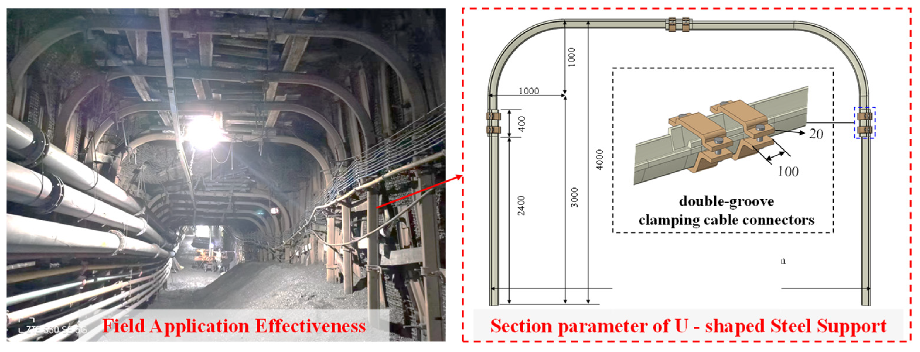
Taking as an example the Tangkou Coal Mine, a typical deep coal mine in China, the roadway at its working face is supported by U29 steel arches. The field support performance and key arch parameters are illustrated in Figure 1.
U-shaped steel supports typically use double-groove clamping cable connectors, as shown in Figure 2. Two straight U-shaped steel segments are connected via clamping cables, with pre-tightening torque applied to the bolts. The axial pressure required to induce relative sliding between the segments defines the joint slip resistance. When the pre-tightening torque is “M”, the pre-tightening force is “F”. By isolating the inner and outer steel segments, the mechanical model of the joint was established (Figure 2). In the schematic diagram, N denotes the force acting on the sidewall-inclined surface of the upper-section steel profile, perpendicular to the slope of the sidewall; P represents the force applied to the sidewall of the outer-section U-shaped steel; α is the angle between the inclined surface of the U-shaped steel and the vertical plumb line; n1 indicates the coefficient of force distribution between the steel profiles, 0 ≤ n1 ≤ 1; n2 corresponds to the clamping cable’s support force distribution coefficient between the steel sections, 0 ≤ n1 ≤ 1.

2.2. Calculation of Joint Slip Resistance

Considering the inner U-steel section as a free-body diagram for force analysis, the cable-clip connector was connected to the U-steel via two bolts. The total pre-tightening force was 2F, and its action line coincided with the center line of the U-steel arch. The angle between the inclined surface of the U-steel and the vertical line is α. The supporting force of the outer U-steel section on the inner U-steel section was divided into two parts: ① The force acting under the upper U-steel ear, n1, is the force distribution coefficient between the U-steel sections, n1F; ② The force N acts on the side of the upper U-steel section, and its direction is perpendicular to the inclined surface of the side. According to the equilibrium condition, we can obtain the following:
2 F 2 n 1 F 2 N sin α = 0
Therefore, the following can be expressed:
N = ( 1 n 1 ) F sin α
Taking the outer U-steel section as a free-body diagram for force analysis, as shown in Figure 2b, according to the law of action and reaction, the forces acting on both sides of the outer U-steel section from the inner U-steel section are N and n1F. The supporting force of the cable-clip on the lower U-steel section is divided into two parts; ① the force acting under the ear of the outer U-steel section, n2, is the supporting force distribution coefficient of the cable-clip between the U-steel sections, n2F, and ② the force P acts on the side of the outer U-steel section in a direction perpendicular to the inclined surface of the side. According to the equilibrium condition, we can obtain the following:
2 n 1 F + 2 ( 1 n 1 ) F sin α sin α = 2 n 2 F + 2 P sin α
Therefore, the following also applies:
P = ( 1 n 2 ) F sin α
The connector connects the two U-steel sections at the joint into one body. Suppose the friction coefficient between the two U-steel sections is f, then the friction force between the connector and the inner U-steel section is 2Ff, and the friction force between the connector and the outer U-steel section is 2 ( n 2 + ( 1 n 2 ) sin α ) F f . Therefore, the friction force between the connector and the inner U-steel section is less than that between the connector and the outer U-steel section, and the connector and the inner U-steel section experience relative sliding. At this moment, the joint slip resistance is as follows:
S = 2 ( 2 F f + 2 n 1 F f + 2 N f )
Substituting Equation (2) into Equation (5) and simplifying, we can obtain:
S = 4 F f ( 1 + n 1 + 1 n 1 sin α )
The relationship through the bolt connection between the pre-tightening force F of the joint bolt and the pre-tightening torque M was calculated. The torque M1 applied by the torque wrench is balanced by the torque M2 that prevents the nut from rotating on the bolt and the friction torque that prevents the nut from rotating within the connector. Thus, we can obtain the following:
F = M t g ( λ + ρ ) d 2 2 + f ( D 1 + d 0 4 )
where λ is the thread lead angle, λ = t g 1 t 0 π d 2 ; ρ is the equivalent friction angle, ρ = t g 1 f ; f is the equivalent friction coefficient, f = 1.155 f 1 ; t 0 is the thread lead; d 2 is the pitch diameter of the thread; f 1 is the friction coefficient between the bolt and the steel plate, generally taken as 0.15–0.2; d 0 is the bolt hole diameter on the connected object; D 1 is the diameter of the inscribed circle on the hexagonal nut.
Substitute Equation (7) into Equation (6) to obtain the following:
S = ( 1 + n 1 + 1 n 1 sin α ) 4 f M t g ( λ + ρ ) d 2 2 + f ( D 1 + d 0 4 )
Based on the yield-pressure support principle, secondary pre-tightening after slippage of the cable-clip joint can enable the joint to continuously maintain a higher support resistance during the working process. Suppose the slip resistance of the joint after secondary pre-tightening to reach a new support equilibrium is P2, and the rate of improvement in the slip resistance of the joint after secondary pre-tightening is evaluated by k, the expression is as follows:
S = k S
where S is the slip resistance of the joint after secondary pre-tightening, and k is the support resistance improvement rate after the secondary pre-tightening of the nut; this value is experimentally determined. S is the slip resistance of the joint after the initial pre-tightening of the nut.

2.3. Principle of Yieldable Support

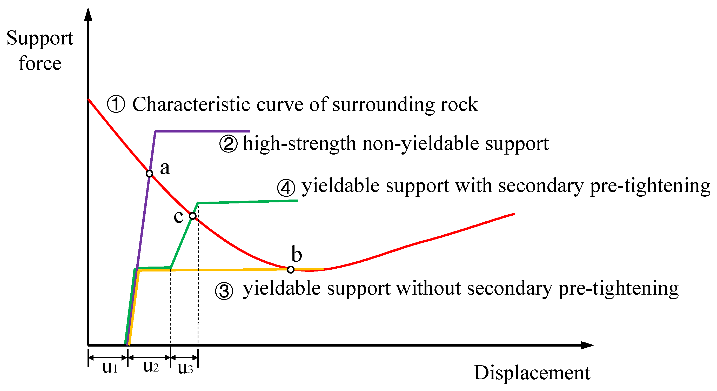
As indicated by the preceding analysis, applying secondary pre-tensioning to the cable clamp joint can further enhance its slip resistance. Through integrating the ground reaction curve and the support characteristic curves of different structural types (Figure 3), the principle of the secondary pre-tensioning yielding support system for a U-shaped steel arch was analyzed.
  • Figure 3 illustrates all types of arch support systems that can be applied when the surrounding rock deformation reaches u1. In the figure, curve ② represents a high-strength non-yield-capacity arch (difficult to yield). Its high slip resistance intersects the ground reaction curve at Point a, requiring greater support force and resulting in higher construction costs. Curve ③ corresponds to a yieldable support without secondary pre-tightening. Its intersection with the ground reaction curve at Point b indicates excessive rock deformation and an insufficient safety margin, leading to inadequately effective support. During the slip phase represented by Curve ④, implementing secondary pre-tensioning when the yielding displacement reaches u2 enhances slip resistance. The modified curve intersects the ground reaction curve at Point c, indicating moderate deformation of the rock and a high safety margin, thereby exemplifying an optimal configuration for yielding support.

3. Axial Compression Testing of U-Shaped Steel Support Joints

To further clarify the slip and bearing characteristics of U-steel support joints after secondary pre-tightening and verify the calculation formula for joint slip resistance, this section reports the axial compression testing conducted on the joints of the yield-type U-steel supports.

3.1. Test Scheme

Two 600 mm U29 steel segments were connected via a 300 mm double-groove clamping cable. M16 bolts (grade 10.9) were used. The physical and mechanical parameters are listed in Table 1.
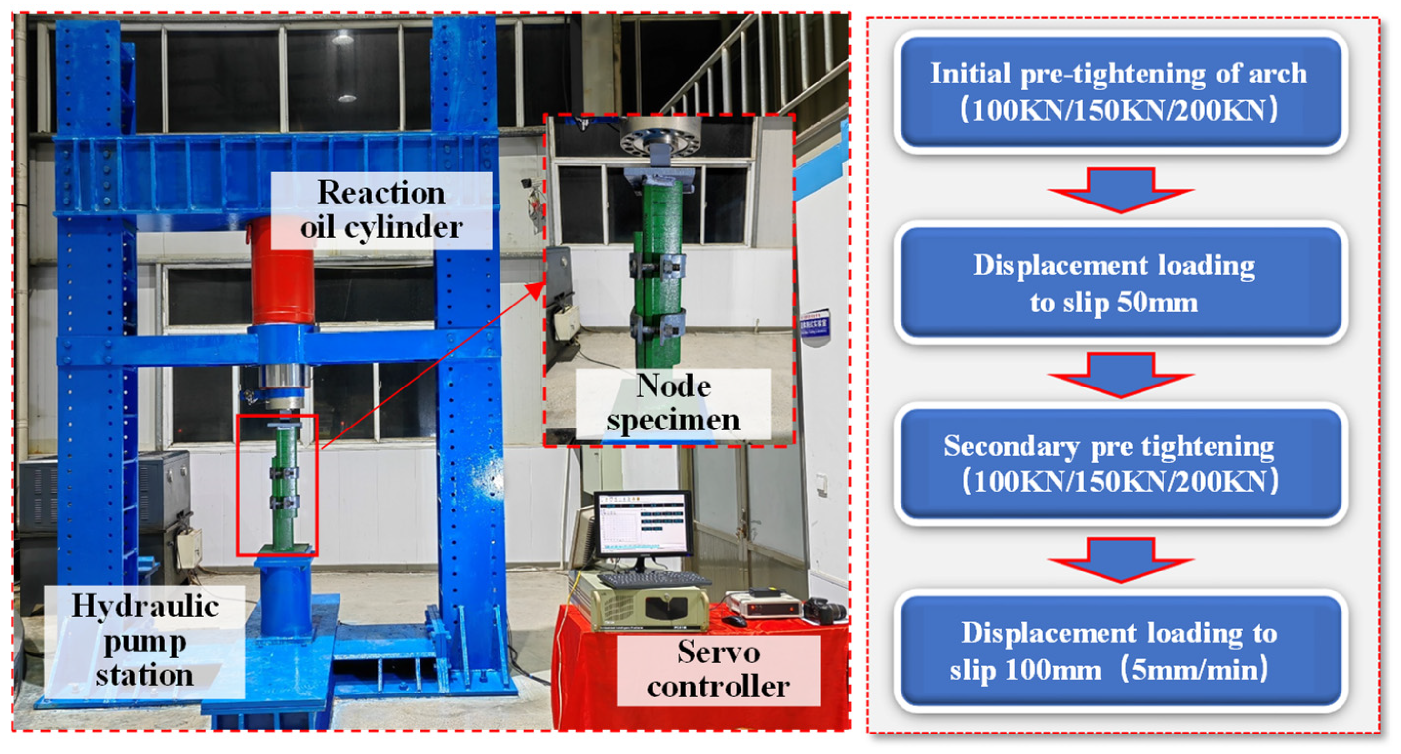
Compression tests were carried out on U-steel joint specimens with three different initial pre-tightening torque values: 100 N·m, 150 N·m, and 200 N·m, respectively. The test process was as follows. After the initial pre-tightening of the cable-clip joint, displacement loading was carried out at a speed of 5 mm/min. When the joint slip value reached 50 mm, the loading was stopped. Secondary pre-tightening of each specimen was carried out according to the initial pre-tightening value, and the displacement loading then continued at a speed of 5 mm/min until the joint slip reached 100 mm; then, the loading was stopped. The test system (Shandong Underground space Safety control engineering Laboratory) and loading process are illustrated in Figure 4.

3.2. Test Results

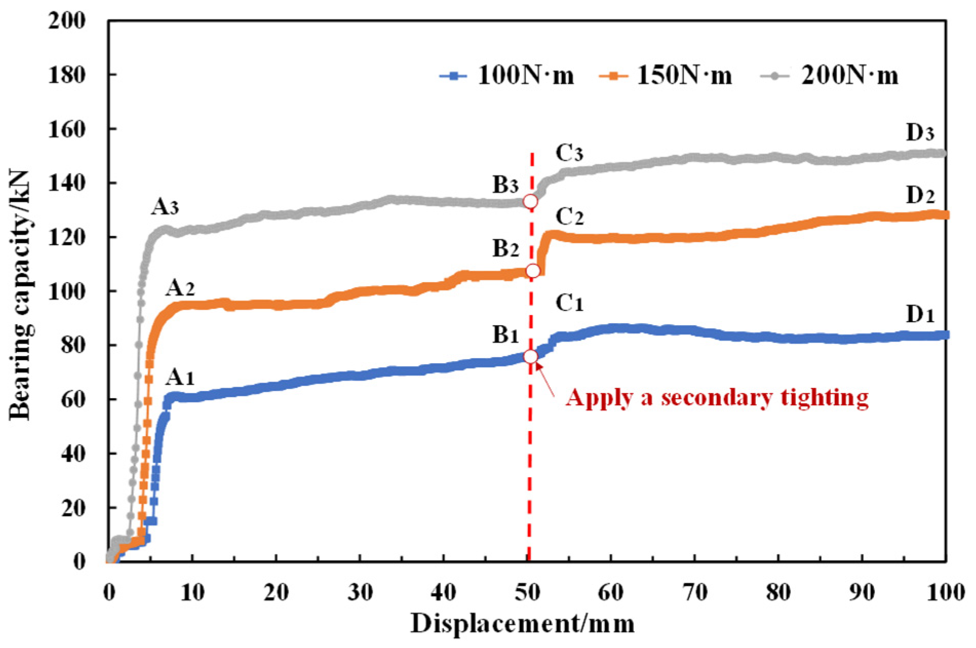
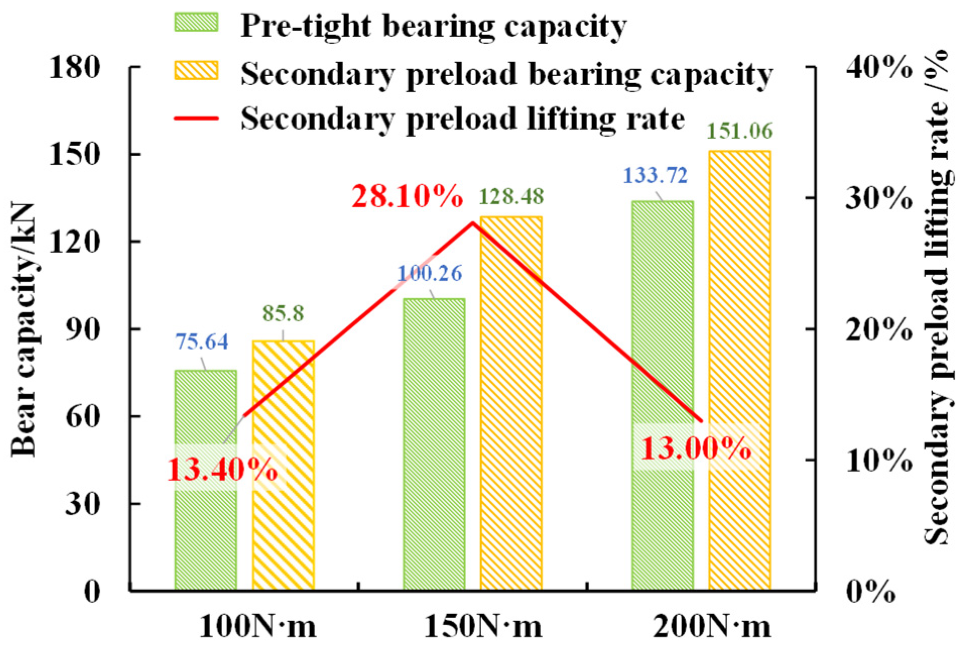
The joint displacement curves of the bearing capacity of U-steel joints under axial compression with different initial pre-tightening torque are shown in Figure 5, and the changes in bearing capacity under different initial torque after secondary pre-tightening are reported in Figure 6.
The analysis illustrated in Figure 5 revealed that the bearing capacity displacement curves were mainly divided into four stages. In the initial bearing stage (OA) at the initial stage of loading, the gaps at the joint are continuously compacted, the bearing capacity shows a rapid linear increase, and there is no obvious slip at the joint; At the first slip stage (AB), when the bearing capacity reaches the same level as the joint’s slip resistance, the joint begins to slip, and the bearing capacity remains basically stable during this process. In the secondary pre-tightening stage (BC), after applying secondary pre-tightening torque to the joint, the joint stops slipping, and the bearing capacity of the specimen rapidly increases again in a linear fashion. During the second slip stage (CD), when the bearing capacity reaches the level of secondary slip resistance, the joint undergoes a second slippage event, and the bearing capacity remains basically stable.
Figure 6 indicates that when the initial torque increased from 100 N·m to 200 N·m, the bearing capacity of the specimen increased by 58.08 kN, at a 76.8% rate of increase. From the perspective of each group, the increase in the bearing capacity of the specimens after secondary pre-tightening was more than 10%. Among the groups, the increase in bearing capacity in the middle-group specimens was the highest, increasing by 28.22 kN, and the increase in bearing capacity after secondary pre-tightening reached 28.10%.
In summary, for the joints with different initial torques, the change trends for the displacement in bearing capacity before and after secondary pre-tightening were basically the same. However, when the initial pre-tightening torque was higher, the first slip resistance and second slip resistance of the specimens increased. There was a turning point in the improvement of the secondary pre-tightening effect; after exceeding a certain pre-tightening torque, the improvement effect of secondary pre-tightening diminished.

3.3. Comparison Between Theoretical and Test Results

Considering the above-mentioned expressions of joint slip resistance before and after secondary pre-tightening, and also the indoor test results, the force distribution coefficient n1 between the U-steel sections at the joint and the supporting force distribution coefficient n2 of the cable-clip between the U-steel sections was calculated, as shown in Table 2. The obtained coefficients were all within a reasonable range, proving the consistency between the theoretical derivation and the indoor test results.
The slip resistance under different pre-tightening torque values was quantified, as shown in Table 3. With the increase in the bolt torque, the slip resistance of the joint also increased. The maximum error between the theoretical values and the test results was only 7.6%, which is within a reasonable range.

4. Numerical Tests on Mechanical Performance Following Secondary Pre-Tightening of Supports

On the basis of the above-mentioned research, numerical experimental studies were carried out on U29 steel joints and supports using 2022 Abaqus software to clarify the influence mechanism of secondary pre-tightening on the overall bearing performance of the supports.

4.1. Joint Simulation and Analysis

4.1.1. Establishing the Joint Model

Referring to the national standard data of U29 steel for mining, the material of the U-steel was 20 Mnk, with a density of 7800 kg/m3, an elastic modulus of 210 GPa, a Poisson’s ratio of 0.27, a yield strength of 335 MPa, a tensile strength of 490 MPa, and elongation of 16%; the yield strength of the cable-clip splint was 355 MPa, and the tensile strength was 600 MPa.
First, the cross-section of the U29 steel was drawn in 2022 CAD software and imported into the Abaqus software; then, the U-steel component was generated by extrusion. Similarly, other components such as cable-clips were generated and then assembled. Hard surface-to-surface contact was applied between the U-steel sections and between the U-steel and the cable-clip, and the friction coefficient was 0.3 [29]

4.1.2. Analysis and Verification of Numerical Results

The axial compression simulation process of the joint was consistent with the indoor testing. The stress nephogram of the joint at the end of the test is shown in Figure 7, and the comparison between the test value and the simulated value of the slip resistance is presented in Table 4.
It can be seen from the above figures that the stress nephograms of the joints under different pre-tightening torque conditions were similar. The maximum stress was located at the cable-clip bolt, and the stress at the other positions was relatively small. The deformation and slip process measured by the numerical testing was basically the same as in the indoor tests. Table 4 reveals that the average error between the test value and the simulated value of slip resistance after the initial pre-tightening was 7.1%, which further proves the rationality of the numerical model.

4.2. Simulation and Analysis of U29 Steel Supports

4.2.1. Establishment of the U29 Steel Support Model

On the basis of the numerical model of the support joint, taking the commonly used four-section U29 steel support method employed in deep roadways as the research object, the positions of the support sections were modelled for the numerical calculations. The parameters in this model were the same as those in the above-mentioned joint simulation; the support parameters and section positions are shown in Figure 8.

4.2.2. Simulation Scheme and Evaluation Index

The test scheme was designed to reflect variables including the absence of secondary pre-tightening torque (Scheme O), the magnitude of the initial pre-tightening torque (Scheme A), the magnitude of the secondary pre-tightening torque (Scheme B), and the timing of the secondary pre-tightening (Scheme C). The detailed scheme is shown in Table 5.
In Scheme O, the initial pre-tightening torque of the cable-clip bolts on the support was 100 N·m, 150 N·m, 200 N·m, 250 N·m, and 300 N·m, respectively. No secondary pre-tightening was carried out during the loading process, and the loading continued until failure. For Scheme A, the initial pre-tightening torque of the cable-clip bolts on the support was 100 N·m, 150 N·m, 200 N·m, 250 N·m, and 300 N·m, respectively. When the yield pressure on the joint reached 50% of the ultimate slippage value, a secondary pre-tightening torque equal to the initial pre-tightening torque was applied, and the loading then continued until failure. In Scheme B, the initial pre-tightening torque of the cable-clip bolts on the support was 200 N·m. When the yield pressure on the joint reached 100 mm, secondary pre-tightening torques of 100 N·m, 150 N·m, 200 N·m, 250 N·m, and 300 N·m, respectively, were applied, and the loading then continued until failure. Scheme C included initial pre-tightening torque of 200 N·m on the cable-clip bolts. When the yield pressure on the joints of the specimens reached 50 mm, 100 mm, 150 mm, 200 mm, and 250 mm, respectively, a secondary pre-tightening torque of 200 N·m was applied, and the loading then continued until failure.
To establish the evaluation indexes, the rate of change in secondary pre-tightening bearing capacity was considered. Under conditions of the same initial pre-tightening magnitude, after applying secondary pre-tightening, the change in the support bearing capacity was compared with that without secondary pre-tightening. Regarding the rate of change in support yield pressure, under conditions of the same initial pre-tightening magnitude, the change in the support yield pressure after applying secondary pre-tightening was compared with that without secondary pre-tightening.

4.2.3. Results Analysis

(1)
Analysis of the Influence of the Initial Pre-tightening Magnitude
Under different magnitudes of initial pre-tightening torque, after applying a secondary pre-tightening torque of 200 N·m, the support bearing capacities were compared. The results are shown in Figure 9a, and the comparison of the joint yield pressure is shown in Figure 9b.
It can be seen from Figure 9a,b that when the initial pre-tightening torque was 100 N·m, after applying secondary pre-tightening, the support bearing capacity increased from 503 kN to 635 kN, and the rate of change in the secondary pre-tightening bearing capacity reached 27.1%. When the initial torque was increased to 300 N·m, after secondary pre-tightening, the support bearing capacity increased by 131 kN compared with when the initial pre-tightening torque was 100 N·m, and the rate of change in the secondary pre-tightening bearing capacity was 2.5%. Thus, it was observed that applying secondary pre-tightening had a certain enhancing effect on the support bearing capacity. However, when the initial torque exceeded 250 N·m, the degree of influence of the secondary pre-tightening on the bearing capacity gradually decreased.
Regarding the support joint yield pressure, when the initial pre-tightening torque was 100 N·m, after applying secondary pre-tightening, the support joint yield pressure decreased from 476 mm to 351 mm, and the change rate of the yield pressure was 26.3%. When the initial torque was 300 N·m, the support joint yield pressure after secondary pre-tightening decreased by 54 mm compared with when the initial pre-tightening torque was 100 N·m, and the change rate of the yield pressure was 5.7%. It was observed that applying secondary pre-tightening had a certain influence on the yield-pressure performance of the support joint. However, with the increase in the initial torque, the influence of secondary pre-tightening on the yield-pressure performance of the support joint gradually decreased.
(2)
Analysis of the Influence of Secondary Pre-tightening Magnitude
Comparison of the support bearing capacities under different magnitudes of secondary pre-tightening torque is shown in Figure 10a, and comparison of the support joint yield pressure is shown in Figure 10b.
Regarding the support bearing capacity, Figure 10a,b reveal that when the initial pre-tightening torque was 200 N·m, after applying secondary pre-tightening torques of 100 N·m and 150 N·m, the support bearing capacity increased from 612 kN to 628 kN and 635 kN, and the rates of change in the secondary pre-tightening bearing capacity were only 2.7% and 3.7%, respectively. When the secondary torque increased to 200 N·m and 300 N·m, the support bearing capacity increased from 612 kN to 687 kN and 716 kN, and the rates of change in the secondary pre-tightening bearing capacity were 12% and 17%, respectively. It was observed that when the secondary pre-tightening torque was less than the initial torque, this had no obvious enhancing effect on the support bearing capacity; the higher the secondary pre-tightening torque, the more significant was the enhancement of the support bearing capacity.
In terms of the support joint yield pressure, under conditions of an initial pre-tightening torque of 200 N·m, after applying secondary pre-tightening torques of 100 N·m and 150 N·m, the support joint yield pressure decreased from 365 mm to 360 mm and 355 mm, and the rates of change in the secondary pre-tightening joint yield pressure amounted to only 1.7% and 2.7%, respectively. When the secondary torque was increased to 200 N·m and 300 N·m, the support joint yield pressure decreased from 365 mm to 330 mm and 315 mm, and the rates of change in the secondary pre-tightening bearing capacity were 9.6% and 13.7%, respectively. Thus, it can be seen that when the secondary pre-tightening torque is less than the initial torque, this has no obvious influence on the yield-pressure performance of the support joint; the higher the secondary pre-tightening torque, the more significant is its the influence on the slippage performance of the support joint.
(3)
Analysis of the Influence of the Timing of Secondary Pre-tightening
Under conditions where both the initial pre-tightening torque and the secondary pre-tightening torque were 200 N·m, comparison of the influence of different timings of secondary pre-tightening on the support bearing capacity is shown in Figure 11a, and comparison of the influences on the support joint yield pressure is shown in Figure 11b.
Regarding the support bearing capacity, it can be seen from Figure 11a,b that when the secondary pre-tightening torque was applied at 30% and 40% of the ultimate yield pressure of the joint, the support bearing capacity increased from 612 kN to 635 kN and 642 kN, and the rates of change in the secondary pre-tightening bearing capacity were only 3.8% and 4.9%, respectively. When the secondary pre-tightening torque was applied at 50% and 70% of the ultimate yield pressure of the joint, the support bearing capacity increased to 687 kN and 706 kN, and the rates of change in the secondary pre-tightening bearing capacity were 12.3% and 15.4%, respectively. Thus, it was observed that when the secondary pre-tightening torque was applied before the joint underwent sufficient slippage, the enhancing effect on the support bearing capacity was limited; meanwhile, when the secondary pre-tightening torque was applied after the joint had slipped by more than 50% of the ultimate yield pressure, the enhancing effect on the support bearing capacity was significant.
Regarding the support joint yield pressure, when the secondary pre-tightening torque was applied at 30% and 40% of the ultimate yield pressure of the joint, the support joint yield pressure decreased from 365 mm to 355 mm and 350 mm, and the rates of change in the secondary pre-tightening joint yield pressure were only 2.7% and 4.1%, respectively. When the secondary pre-tightening torque was applied at 50% and 70% of the joint’s ultimate yield pressure, the yield pressure on the joint decreased from 365 mm to 330 mm and 310 mm, and the rates of change in the secondary pre-tightening joint yield pressure were only 12.3% and 15.1%, respectively. It was observed that when the secondary pre-tightening torque was applied before the joint had slipped sufficiently, the degree of influence degree on the yield-pressure performance of the support was low; when the secondary pre-tightening torque was applied after the joint had slipped by more than 50% of the ultimate yield pressure, the influence on the support’s yield pressure performance was significant.

4.3. Summary and Engineering Suggestions

Applying secondary pre-tightening torque to the cable-clip joint can significantly enhance the bearing capacity of the support. However, in this study, when the initial torque was greater than 250 N·m and the same secondary pre-tightening torque was applied, the degrees of influence on the bearing capacity and the yield-pressure performance of the support were within 5% and 10%, respectively. In practical engineering, it is recommended to perform secondary pre-tightening on the cable-clip joints of yield-type supports. Taking the cable-clip joint of the U29 steel support as an example, the initial pre-tightening torque is preferably 250 N·m.
The larger the secondary pre-tightening torque, the more significant were the influence on the bearing capacity of the support and the yield-pressure performance of the joint. When the secondary pre-tightening torque was less than the initial torque, the increase in the support bearing capacity was less than 5%. For practical engineering applications, taking the cable-clip joint of the U29 steel support as an example, it is recommended that the secondary pre-tightening torque should be greater than the initial pre-tightening torque.
When secondary pre-tightening was applied before the support joint has undergone sufficient slippage, the enhancing effect on the support bearing capacity was limited; when the joint slippage exceeded 50% of the ultimate slippage, applying the secondary pre-tightening torque had a significant enhancing effect on the support bearing capacity. For practical engineering purposes, taking the cable-clip joint of the U29 steel support as an example, it is recommended that secondary pre-tightening should be applied when the amount of joint slippage is not less than 200 mm.

5. Conclusions

Taking the commonly used U29 steel support (specific to underground coal mine applications) as the research object, the expression of the slip resistance of the cable-clip joint after secondary pre-tightening was established and verified through indoor axial compression tests. On this basis, numerical tests were carried out to determine the influence mechanisms of different magnitudes of initial pre-tightening torque and secondary pre-tightening torque as well as the timing of secondary pre-tightening. The findings specific to U29 steel supports and their general implications are summarized as follows:
(1)
Initial pre-tightening torque effects (U29-specific findings)
When the initial torque exceeded 250 N·m, the influence of secondary pre-tightening on both bearing capacity and joint yield-pressure performance demonstrated a gradually decreasing trend. This threshold appears to characterize U29′s material properties and cross-sectional geometry;
(2)
Secondary pre-tightening torque (generalizable principles)
The enhanced effect on bearing capacity showed a positive correlation with torque magnitude. Notably, when secondary torque remained below initial torque levels (a relationship potentially applicable to other U-shaped supports), no significant improvement in joint performance was observed;
(3)
Secondary pre-tightening timing (system-dependent phenomenon)
The timing of the secondary pre-tightening critically affected the U29′s performance. Limited enhancement occurred when tightening was applied before the joint slip reached the critical threshold; significant improvements emerged when tightening was implemented after exceeding 50% of the ultimate slip (this slip-dependent behavior may vary with support stiffness).
Considering the generalizability of the current study, while the fundamental torque–slip relationship provides transferable insights, the specific thresholds (250 N·m torque limit, 50% slip criterion) are intrinsically tied to U29′s dimensional parameters. For alternative U-shaped supports (e.g., U36 or U43 profiles), these parameters require recalibration through adjustment of material properties, modification of gross-sectional geometry, site-specific analysis of load conditions, and so on.
Future research should include comparative studies extending to U36/U43 steel supports with varied rib configurations, in addition to parametric investigations on flange thickness (6–10 mm range) and yield strength (235–355 MPa grades).
Author Contributions

Conceptualization, Y.H. and Y.W.; software, H.T.; investigation, H.Y.; data curation, Y.W.; writing—original draft preparation, X.W. and H.T.; funding acquisition, Y.H. All authors have read and agreed to the published version of the manuscript.

Funding

This research was funded by the National Key Research and Development Program of China, grant number 4230721.

Institutional Review Board Statement

Not applicable.

Informed Consent Statement

Not applicable.

Data Availability Statement

The original contributions presented in this study are included in the article; further inquiries can be directed to the corresponding authors.

Conflicts of Interest

The authors declare no conflict of interest.

References

  1. He, M.C.; Wang, Q.; Wu, Q. Innovation and future of mining rock mechanics. J. Rock Mech. Geotech. 2021, 13, 1–21. [Google Scholar]
  2. Kang, H.P. Seventy years development and prospects of strata control technologies for coal mine roadways in China. Chin. J. Rock. Mech. Eng. 2021, 40, 1–30. [Google Scholar]
  3. Xie, Z.Z.; He, Z.; Xiang, Z.; Zhang, N.; Su, J.B.; Li, Y.L.; Zhang, C.H. Deformation failure characteristics and maintenance control technologies of high-stress crossing-seam roadways: A case study. Appl. Sci. 2024, 13, 4442. [Google Scholar]
  4. Huang, Y.B.; Wang, Q.; Gao, H.K.; Jiang, Z.H.; Li, S.; Chen, K. Failure mechanism and construction process optimization of deep soft rock chamber group. J. China Univ. Min. Technol. 2021, 50, 69–78. [Google Scholar]
  5. Bednarek, Ł.; Małkowski, P.; Niedbalski, Z.; Mucha, K. Steel Arch and Rock Bolt Support in Terms of the Gateroad Stability Maintaining Behind the Longwall Face. Appl. Sci. 2024, 14, 3594. [Google Scholar] [CrossRef]
  6. Wang, D.C.; Wang, Q.; Li, S.C.; Wang, F.W.; Ruan, G.Q.; Shao, X.; Liu, W.J.; Wang, X. Mechanism and control measures of deformation and failure of surrounding rock in goaf excavation of deep well fully mechanized top coal caving. J. Min. Saf. Eng. 2014, 31, 665–673. [Google Scholar]
  7. Hafeezur, R.; Abdul, M.N.; J-joo, K.; Han-Kyu, Y. Empirical Evaluation of Rock Mass Rating and Tunneling Quality Index System for Tunnel Support Design. Appl. Sci. 2018, 8, 782. [Google Scholar] [CrossRef]
  8. Huang, Y.B.; Jiang, B.; Ma, Y.K.; Wei, H.Y.; Zang, J.C.; Gao, X. Study on Asymmetric Failure and Control Measures of Lining in Deep Large Section Chamber. Energies 2021, 14, 4075. [Google Scholar] [CrossRef]
  9. Wang, B.; Wang, J.; Wu, D.X.; Zhao, Y.D.; Zhang, B.; Li, Z. Research on the Application of Compression Support System in Soft Rock Large Deformation Highway Tunnels. J. Railw. Sci. Eng. 2016, 13, 1985–1993. [Google Scholar]
  10. You, C.A. Calculation of Internal Forces of U-shaped Steel Shrinkable Support after Shrinkage. J. Geotech. Eng. 2000, 5, 604–607. [Google Scholar]
  11. You, C.A. Stability Analysis of U-shaped Steel Shrinkable Support. J. Rock Mech. Geotech. 2002, 11, 1672–1675. [Google Scholar]
  12. Rodriguez, R.; Diaz-Aguado, M.B. Deduction and use of an analytical expression for the characteristic curve of a support based on yielding steel ribs. Tunn. Undergr. Space Technol. 2013, 33, 159–170. [Google Scholar] [CrossRef]
  13. He, M.C.; Wang, B.; Tao, Z.G.; Qiao, Y.F.; Xiao, Y.M. Research on Adaptive Node Axial Compression Performance of Steel Supports in Large Deformation Tunnels. Chin. J. Highw. 2021, 34, 1–10. [Google Scholar]
  14. Jiao, Y.S.; Wang, X. Improvement of the U-shaped steel sets for supporting the roadways in loose thick coal seam. Int. J. Rock Mech. Min. 2013, 60, 19–25. [Google Scholar] [CrossRef]
  15. Huang, Y.; Zhang, Y.; Xue, H.; Tian, H.; Li, Y. The Bearing Performance and Sectional Design Method of Yielding U-Shaped Steel Support. Appl. Sci. 2025, 15, 3203. [Google Scholar] [CrossRef]
  16. Zhao, Y.; Liu, N.; Zheng, X. Mechanical model for controlling floor heave in deep roadways with U-shaped steel closed support. Int. J. Min. Sci. Technol. 2015, 25, 713–720. [Google Scholar] [CrossRef]
  17. Chao, W.; Xiaoyi, C.; Jian, D.Z. Stability Mechanism and Repair Method of U-Shaped Steel Reverse Arch Support in Soft Floor Roadway. Adv. Civ. Eng. 2020, 2020, 8814365. [Google Scholar]
  18. Heinz, E. Gotthard base tunnel, Switzerland experiences with different tunnelling methods. In Proceedings of the 2nd Congresso Brasileiro de Túneis eEstruturas Subterráneas Seminário Internacional, Sao Paulo, Brazil, January 2008. [Google Scholar]
  19. Waclawik, P.; Kukutsch, R.; Konicek, P. Stress State Monitoring in the Surroundings of the Roadway Ahead of Longwall Mining. Procedia Eng. 2017, 191, 560–567. [Google Scholar] [CrossRef]
  20. Hou, C.J.; Zhang, S.D.; Dong, Z.Z.; Li, Y. Mechanical properties of bolt connections for retractable metal brackets. J. China Acad. Min. Technol. 1983, 4, 14–28. [Google Scholar]
  21. Xie, W.B.; Jing, S.G.; Wang, T.; Reng, Y.K.; Zhang, N. Stability and Control Technology of U-shaped Steel Support Structure. J. Rock Mech. Geotech. 2010, 29, 3743–3748. [Google Scholar]
  22. Zhang, H.W.; Zhuang, Y.S.; Wu, N.; Gao, X.D.; Zheng, J. Experimental study on the bearing capacity and stability of U-shaped steel flexible supports. Mech. Res. Appl. 2020, 33, 86–91. [Google Scholar]
  23. Dong, B.; Yang, J.J.; Yin, H.B.; Xu, G.L. Performance Analysis of Steel Arch Nodes in Tunnels. Tunn. Constr. 2021, 41, 1524–1529. [Google Scholar]
  24. Horyl, P.; Richard, Š.; Pavel, M. Behaviour of Frictional Joints in Steel Arch Yielding Supports. Arch. Min. Sci. 2014, 59, 781–792. [Google Scholar] [CrossRef]
  25. Liu, Z.J.; Li, J.; Gan, L. Research on Buckling Mechanism of U Type Steel Support’s Pinnas Based on ANSYS. Adv. Mater. Res. 2012, 1669, 1271–1274. [Google Scholar] [CrossRef]
  26. Tan, X.; Chen, W.; Liu, H. A combined supporting system based on foamed concrete and U-shaped steel for underground coal mine roadways undergoing large deformations. Tunn. Undergr. Space Technol. 2017, 68, 196–210. [Google Scholar] [CrossRef]
  27. Zhi, L.S.; Jiang, S.G.; Xie, W.B. Improvement on the Key Element of Flexible U-Shaped Steel Support and Its Field Applications. Adv. Civ. Eng. 2022, 2022, 8646858. [Google Scholar]
  28. You, C.A. Shrinkage Analysis of U-shaped Steel Shrinkable Support. Coal J. 1994, 3, 270–277. [Google Scholar]
  29. Liu, L.M.; Zhang, J.P. Analysis and simulation of stress and deformation of U-shaped steel supports under different geostress conditions. Coal Technol. 2017, 36, 234–236. [Google Scholar]
Figure 1. Field application and cross-sectional parameters of the arch.
Applsci 15 03803 g001
Figure 2. Mechanical model of pre tensioned cable clamping nodes.
Applsci 15 03803 g002
Figure 3. Mechanism diagram of compression action.
Applsci 15 03803 g003
Figure 4. Experimental system and process.
Applsci 15 03803 g004
Figure 5. Slip resistance–displacement curves.
Applsci 15 03803 g005
Figure 6. Comparison of slip resistance under secondary pre-tightening.
Applsci 15 03803 g006
Figure 7. Stress cloud map of node specimen.
Applsci 15 03803 g007
Figure 8. Assembly drawing of U-shaped steel bracket model.
Applsci 15 03803 g008
Figure 9. Analysis of the impact before and after secondary pre-tightening of the bracket.
Applsci 15 03803 g009
Figure 10. Analysis of the influence of secondary pre-tightening of brackets.
Applsci 15 03803 g010
Figure 11. Analysis of the impact of secondary pre-tightening of brackets.
Applsci 15 03803 g011
Table 1. Physical and mechanical parameters of nodes.
Calculated ParametersValue
Friction coefficient between section steels f0.2
Angle between the inclined plane of the section steel and the vertical line α 14.2
Lead of thread t0/mm2
Mean diameter of thread d2/mm14.71
Bolt hole diameter of the connected object d0/mm18
Diameter of the inscribed circle of the hexagonal nut D1/mm24
Friction coefficient between the bolt and the steel plate f10.15
Slidable length of the node/mm200
Table 2. Distribution Coefficient Calculations.
Bolt Torque/N·mInitial Slip Resistance/kNDistribution Coefficient/n1Distribution Coefficient/n2
10060.70.640.42
15095.00.620.40
200122.80.640.43
Table 3. Comparison of Theoretical and Experimental Values of Slip Resistance.
Initial Pre-Tightening Torque/N·mTheoretical Value of Initial Slip Resistance/kNExperimental Value of Initial Slip Resistance/kNError/%
10065.360.77.6
15090.095.05.3
200130.1122.85.9
Table 4. Comparison of Experimental and Simulated Values of Slip Resistance.
Bolt Torque/
N·m
Experimental Value of Initial Slip Resistance/kNSimulated Value of Initial Slip Resistance/kNError/%
10060.465.58.4
15094.999.24.3
200122.7133.48.7
Table 5. Simulation test scheme for the effect of secondary pre-tightening.
SchemeInitial Pre-Tightening Value (i)Secondary Pre-Tightening Value (j)Timing of Secondary Pre-Tightening (t)
O100 N·m, 150 N·m, 200 N·m, 250 N·m, 300 N·mnonenone
A100 N·m, 150 N·m, 200 N·m, 250 N·m, 300 N·m200 N·m50%du
B200 N·m100 N·m, 150 N·m, 200 N·m, 250 N·m, 300 N·m50%du
C200 N·m200 N·m30%du, 40%du, 50%du, 60%du, 70%du
Disclaimer/Publisher’s Note: The statements, opinions and data contained in all publications are solely those of the individual author(s) and contributor(s) and not of MDPI and/or the editor(s). MDPI and/or the editor(s) disclaim responsibility for any injury to people or property resulting from any ideas, methods, instructions or products referred to in the content.