Article

Effect of Lubricant Young’s Modulus on Surface Settlement Control During Pipe-Roof Construction Using Pipe-Jacking Method

1
Department of Earth Resources Engineering, Kyushu University, Fukuoka 819-0395, Japan
2
School of Civil Engineering, Sun Yat-sen University, Guangzhou 510275, China
*
Authors to whom correspondence should be addressed.
Appl. Sci. 2025, 15(7), 3713; https://doi.org/10.3390/app15073713
Submission received: 17 February 2025 / Revised: 22 March 2025 / Accepted: 26 March 2025 / Published: 28 March 2025
(This article belongs to the Section Civil Engineering)

Abstract

:
During pipe-roof construction using pipe-jacking technology, lubricants are injected into the tail void to reduce pipe–soil friction and minimize soil loss. However, research on ground settlement caused by multiple adjacent pipe jackings remains limited, and the influence of lubricant Young’s modulus on ground settlement control is not clear. To address these gaps, this study conducts a comprehensive investigation using a Fast Lagrangian Analysis of Continua in 3 Dimensions (FLAC3D). Initially, the research model is validated against a pipe-roof case in Japan. Subsequently, ground response characteristics are simulated under lubricants with different Young’s moduli, considering four burial depths, two pipe-roof arrangements (“gate-shaped” and “horseshoe-shaped”), and two tail voids. The results indicate that low-stiffness lubricants mobilize greater surface settlement, while increasing the lubricant Young’s modulus more markedly optimizes the interaction among adjacent pipelines, thereby greatly alleviating the settlement. Nonetheless, the control effectiveness of lubricant on the settlement is influenced by other factors. Increasing burial depths and tail voids weaken the lubricant’s capacity to mitigate surface settlement. In contrast, the horseshoe-type arrangement is more conducive to the lubricant’s control effect on surface settlement than the gate-type system. Moreover, under these three cases, an increase in the lubricant Young’s modulus can more substantially reduce surface settlement. These findings provide valuable insights for controlling ground settlement during pipe-roof construction.

1. Introduction

As a trenchless construction method, pipe-jacking technology offers advantages, including precise guidance, remote operation, minimal traffic disruption, and effective control of working face stability [1]. These attributes have rendered it widely applicable in the development and utilization of urban underground spaces. However, considering the surrounding heavy traffic and sensitive facilities, achieving stringent control over soil disturbance and surface settlement poses arduous challenges to the construction of pipe-jacking projects, particularly in cases involving shallow burial and soft soil foundations [2]. Extensive engineering practice has demonstrated that strategically integrating pipe-jacking methods with the pipe-roof pre-construction method (PPM) constitutes a viable countermeasure [3,4,5,6,7]. Since its initial application in the construction of the Antwerp Metro in Belgium, the PPM has emerged as a critical auxiliary technique for trenchless construction in urban underground spaces, due to its superior control over surface settlement [8,9,10,11].
At present, pipe-roof construction primarily employs the directional follow-pipe drilling technology [9], the auger boring method [1], and the slurry pipe-jacking method [12]. Compared to other pipe-roof construction methods, the slurry pipe-jacking method evinces the following characteristics: (1) considerable pipes are successively jacked at small intervals; and (2) tail voids form around the jacked pipes, necessitating mud injection. Inevitably, repeated soil disturbance and over-excavation precipitate surface settlement. In some cases, settlement occurring during the phase of pipe-roof construction using the slurry pipe-jacking method (PPJM) accounts for up to 75% of the total settlement in underground construction [13,14]. Therefore, as an auxiliary process intended to alleviate the disturbances to the surrounding stratum induced by trenchless construction, it is crucial to ensure that the impacts associated with PPJM are effectively controlled.
Existing studies indicate that surface displacement during the jacking phase of PPJM results from the combined effects of settlement due to soil loss and uplift induced by lubricant injection; in contrast, surface settlement during the pause jacking phase is predominantly attributable to consolidation [14,15]. Throughout the construction process, lubricants are employed to mitigate soil loss and support tail voids. Consequently, they play a critical role in controlling surface settlement caused by PPJM [16]. In view of this, Maehara et al. [17], Shimada et al. [18], Zhou et al. [19], and Liu et al. [20] focused on developing new lubricants with more prominent friction reduction and better support capabilities. They experimentally evaluated the friction-reduction efficiency and surface settlement inhibition effects of various lubricants, elucidating the influence of condensation force, composition, filter loss, and yield point on surface settlement during pipe-roof construction. In addition, the injection pressure, gel time, and post-gel strength of the lubricant—as well as its permeability characteristics in different soils and distribution patterns within the tail voids—also influence its effectiveness in controlling surface settlement [21,22,23]. However, to simplify analysis, lubricants are often modeled as elastic bodies in numerical simulations, where the lubricant Young’s modulus characterizes its stiffness and resistance to deformation [24,25,26]. A higher Young’s modulus indicates that the lubricant deforms less under load, thereby more effectively supporting the tail void and reducing the surface settlement caused by PPJM. Additionally, Ma et al. [12] examined the protection of underground adjacent structures using the PPM during trenchless construction, concentrating on the performance of new lubricants with time-enhanced mechanical properties. The results indicated that the high-stiffness lubricant provides augmented protection for adjacent existing structures; however, its protective capacity is constrained by the pipe-roof disposition and the spacing between tunnels. Thus, the impact of the lubricant Young’s modulus on controlling surface settlement is likely modulated by additional factors. Nevertheless, its specific influence under varying construction conditions remains unclear and needs further investigation.
The above revisit suggests that, although the physical and mechanical properties of lubricants have been included in research on PPJM, the influence of lubricant Young’s modulus and its interaction with construction conditions—such as pipe-roof arrangement, burial depth, and tail void size—on the settlement has yet to be explored in the literature and warrants further investigation. Using FLAC3D, this paper simulates the influence of variations in lubricant Young’s modulus on the surface settlement under different construction conditions. First, the reliability of the modeling method is validated by reproducing a Japanese engineering case. Subsequently, numerical simulations are performed, considering four burial depths, two pipe-roof dispositions (“gate-shaped” and “horseshoe-shaped”), and two tail voids, to disclose the impact of Young’s modulus and construction conditions on the surface settlement. Finally, the conclusions offer novel insights into the surface settlement from the perspective of lubricant Young’s modulus and its interaction with construction conditions. These insights contribute to the more ubiquitous implementation of PPJM in trenchless applications.

2. Numerical Model Establishment and Validation

2.1. Case Overview

The national highway transportation hub near Furujima Station in Naha City spans the Aja River, with a box culvert for drainage embedded along the river. With the increasing demand for drainage capacity, a new drainage pipeline adjacent to the existing culvert was planned to enhance the serviceability. The new pipeline is situated to the left of the existing one, with a jacking distance of 60 m, as shown in Figure 1. Given that pipelines cross beneath the transportation hub and that the jacking zone is mainly composed of soft clay, the “rectangular pipe jacking + PPJM” method was employed to alleviate surface settlement during the construction of both the existing and new pipelines.
The detailed case parameters are illustrated in Figure 2. The main underground structures were constructed by box culverts, both measuring 6.4 m in height and 7.4 m in width. The existing and new pipe roofs, installed via the PPJM method, comprise 28 and 19 steel pipelines, respectively, each with a diameter of 800 mm and a total length of 60 m. Each steel pipeline consists of multiple steel pipe strings, each 900 mm long, with a tail void of 20 mm, and the center-to-center distance between adjacent steel pipe strings is also 900 mm. The existing pipe roof follows a conventional layout, commonly known as a ‘gate-shaped’ system. In contrast, the new pipe roof is designed based on the existing structure, featuring steel pipelines only along its upper section and left side—an arrangement typically referred to as the ‘L-shaped’ system [12]. In addition, the tunnels are buried at a depth of 7.5 m and spaced 1.85 m apart, while the upper boundaries of the pipe roofs are positioned 5.7 m below the surface. Therefore, the spacing between the pipe roof and the tunnel is 1.16 m at the upper boundary and 0.505 m along the side.
According to geological surveys, the soil layers encountered during the construction process are dominated by soft soils—namely, gravel clay and clay layers—with their mechanical properties presented in Table 1.

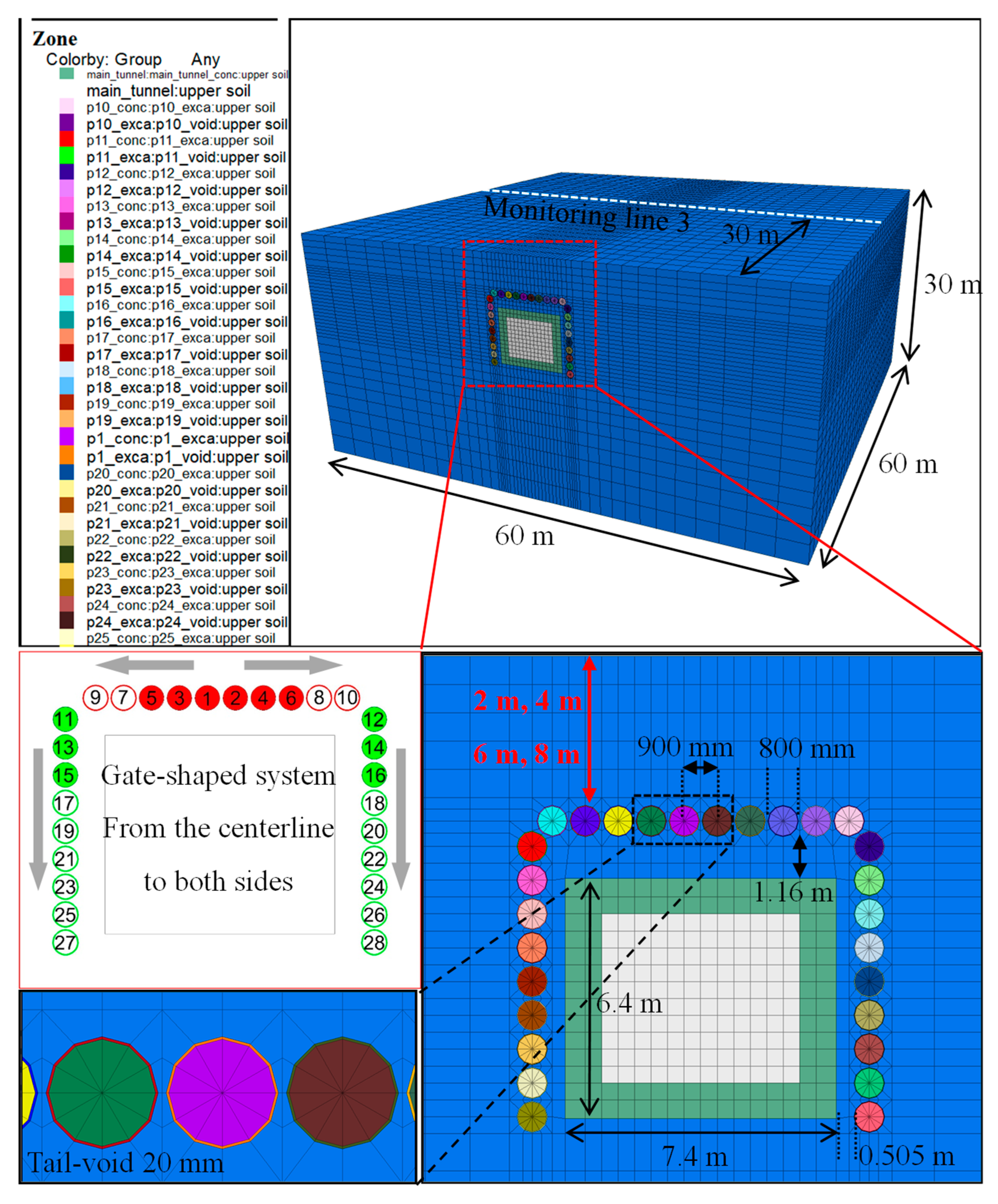
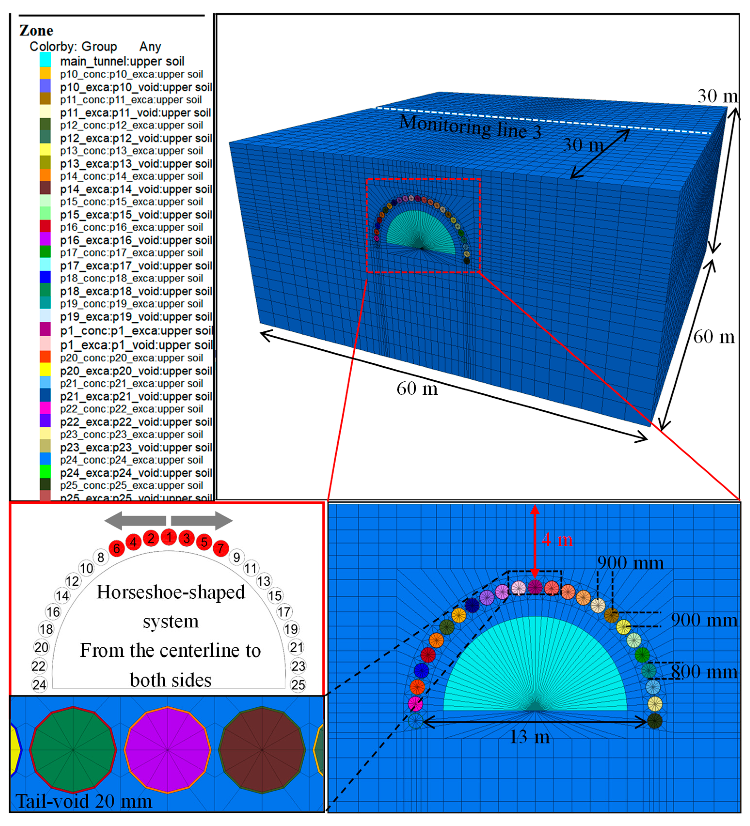
2.2. Numerical Model Setup

FLAC3D 5.0, a finite difference analysis software, is frequently adopted to simulate the ground response caused by pipe-jacking construction [27]. In numerical simulations of the pipe-jacking process, two primary control methodologies are commonly used: the stress control method [28] and the displacement control method [29]. For the stress control method, pipe–soil friction and jacking force must be assigned at the outset of the simulation, typically derived from various empirical or theoretical equations. Conversely, since the jacking direction and displacement are well-defined in the design of pipe jacking, it is sufficient to input only the actual jacking speed to ensure the accuracy of the simulation results in the displacement control method. Therefore, this study selects the displacement control method for simulation analysis.
A FLAC 3D model was built based on the case analysis, as depicted in Figure 3. Except for the steel pipeline, which was modeled by shell elements, all other components were represented using solid elements. It should be noted that the tail void is assumed to be uniformly filled with lubricant, which is modeled as a solid element using the “equivalent layer” method [24,25,26]. Consequently, direct contact between the pipe and soil was precluded. To realistically simulate the pipe–lubricant–soil interaction during the jacking process, specific soil–pipe and pipe–lubricant contact conditions were defined. The model’s cross-sectional dimensions were defined as 80 m in width and 40 m in height, with a jacking length of 60 m. To avoid boundary effects, the left and right boundaries were set at a distance equal to about 5 times the box culvert width from the tunnel boundary [29]. Meanwhile, the model was constrained to the corresponding horizontal displacement on all sides. The top surface was simulated as a free surface, whereas the bottom was fixed using rollers. Moreover, the soil was assumed to be homogeneous and modeled by the Mohr–Coulomb failure criterion, while other components, including “the equivalent layer”, were treated as isotropic elastic bodies.
It is assumed that the simulation process mirrors the actual construction process, with the monitoring scheme designed based on the real project conditions (Figure 1), as delineated by the white lines (Line 1 and Line 2) in Figure 3. Additionally, special attention is given to Point O, which denotes the intersection of the monitoring lines. Firstly, the existing structure was included in the initial equilibrium step, and the displacements from this step were reset to zero to eliminate the interference of soil consolidation and the existing structure on the results. Following this, 19 steel pipelines were sequentially jacked in an L-shaped arrangement to form the new pipe roof (Figure 3, from ① to ⑲). Finally, the new tunnel was completed. Throughout the jacking process, the consolidation of the lubricant injected into the tail void was considered, with its mechanical properties evolving over time, as detailed in Table 2. Additionally, a control group was established to investigate the influence of lubricant stiffness on surface settlement, featuring a lubricant with a Young’s modulus of 0.23 MPa, a Poisson’s ratio of 0.4, and a density of 2100 kg/m3. The properties of the contact were based on Khazaei’s direct-shear experiments, with cohesion and friction angles of 2.66 kPa and 9.89°, respectively [30]. Additional input parameters involved in the simulation process are listed in Table 1 and Table 3.

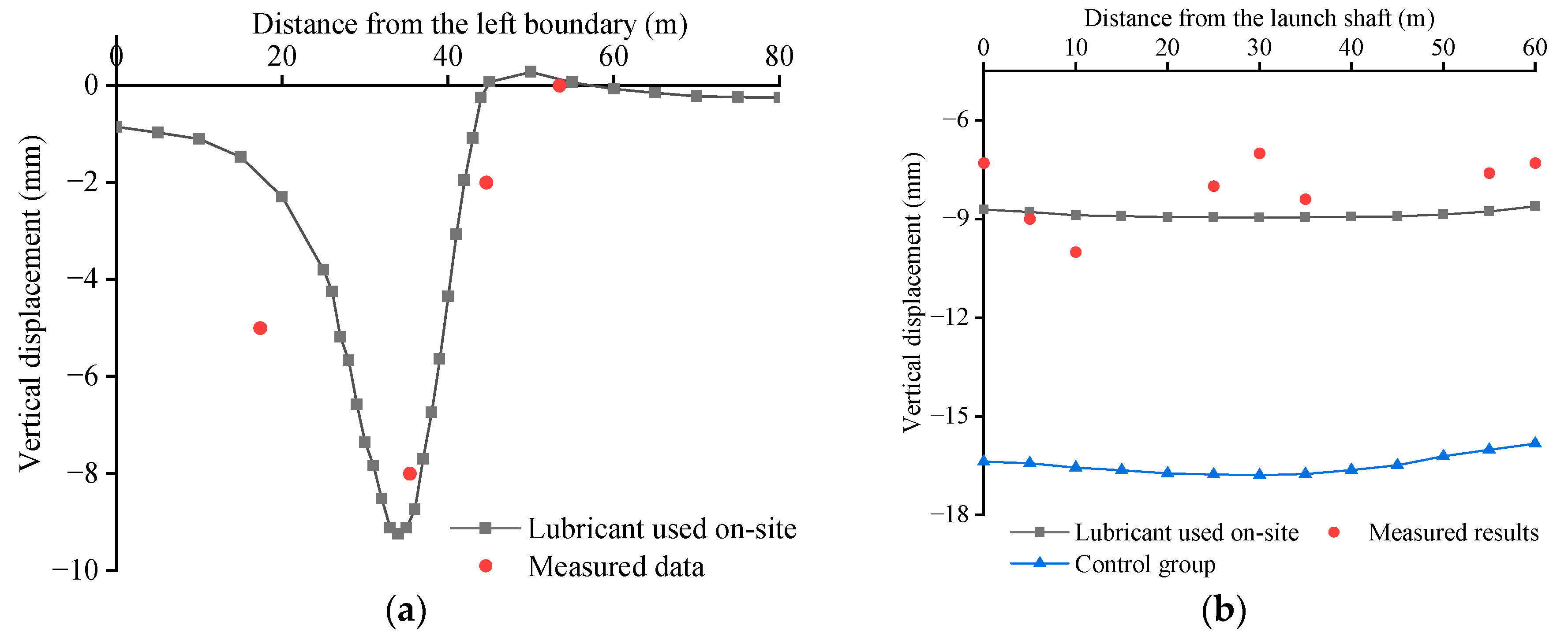
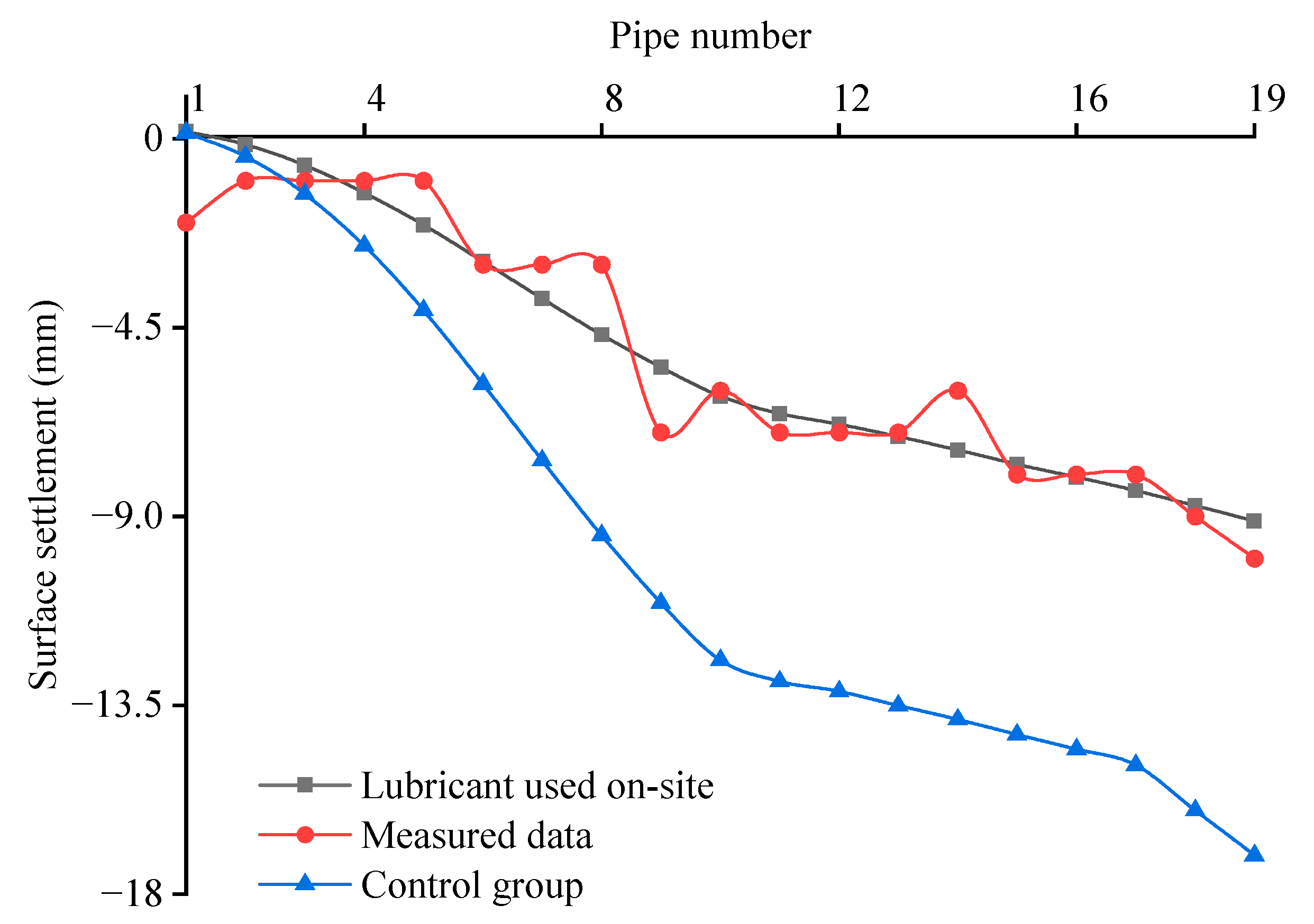
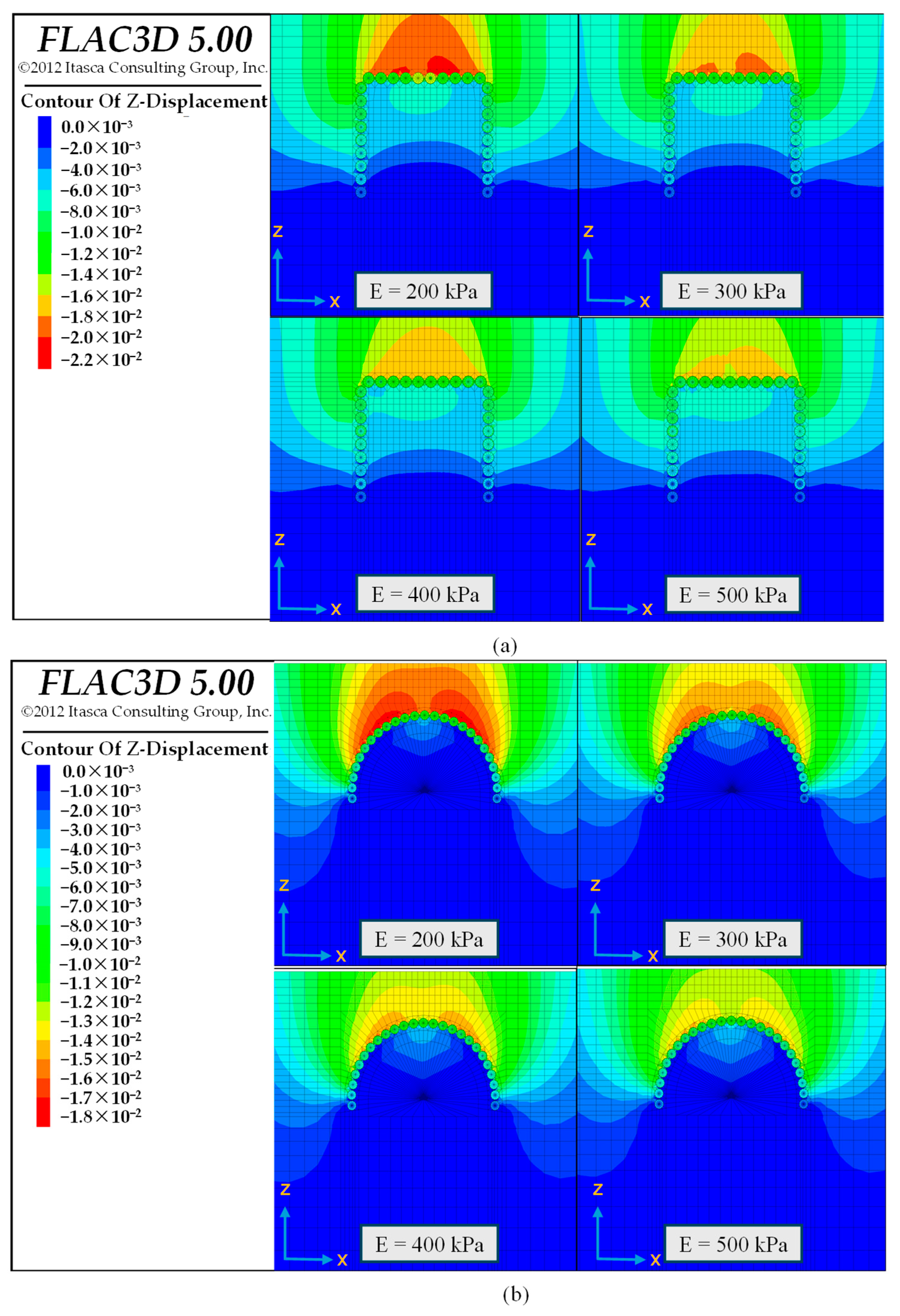
2.3. Validation Result and Influence Mechanism of Lubricant Young’s Modulus

The L-shaped arrangement was implemented on-site for the sequential jacking of steel pipelines, with ground displacement monitored as a reference indicator for analysis. Although the main tunnel construction has been finalized, the validation results are confined to a comparison of surface settlement values recorded during the construction phase of the new pipe roof, in accordance with the objective of this study. In shallow-buried soft foundations, significant discrepancies are often observed between numerical results and monitoring data. Consequently, the measured data were applied to calibrate the model, aiming to achieve a numerical representation that closely replicates the actual deformation. The calibrated model is then utilized to simulate the effect of the lubricant Young’s modulus and its interaction with construction conditions on surface settlement.
Figure 4 compares the simulation results with actual monitoring data after completing the new pipe roof. The black curves correspond to the simulation results for the lubricant used on-site. Figure 4a displays the transverse settlement trough (Line 1), where a notable error appears at the leftmost monitoring point. At this location, the measured settlement is approximately 5 mm, whereas the numerical simulation result is around 2.5 mm—merely half of the measured value. However, the actual settlement peak reaches 8 mm, which is slightly lower than the peak value from the simulation (9.5 mm). Despite these variations, discrepancies elsewhere persist at minimal levels, and, overall, the simulation and monitoring data exhibit comparable transverse settlement troughs. Figure 4b depicts the surface settlement curve located directly above the pipe-roof centerline (Line 2). The simulation results stabilize at approximately 8.9 mm, whereas the actual surface displacement fluctuates along the entire monitoring line, likely due to the assumption in the simulation that the lubricant is uniformly distributed in the tail void. The maximum difference occurs at the midpoint of the jacking direction (Point O), where the field monitoring value is around 7 mm, resulting in an error of approximately 20%. Nevertheless, both curves show a similar trend. This result is deemed reasonable, as similar findings have been reported in previous studies [31].
To examine the impact of lubricant Young’s modulus on surface settlement induced by pipe-roof construction, an additional simulation was conducted for a control group with a lower Young’s modulus, as presented in Figure 4b and Figure 5. In the figure, the blue and black curves represent the simulation results for the control group and the lubricant used on-site, respectively. The results indicate that the vertical displacement caused by the lubricant with a lower Young’s modulus is substantially higher than that produced by the lubricant with a higher Young’s modulus (Figure 4b). To facilitate further analysis, the surface settlement at monitoring point O was recorded after the jacking of each steel pipeline, as shown in Figure 5. The simulation results for the two scenarios follow similar trends and can be broadly divided into two phases. In the first stage, the steel pipelines (①~⑩) at the same horizontal level were jacked, leading to a rapid increase in ground settlement. Conversely, in the second stage, the steel pipelines (⑪~⑲) on the same side were jacked, resulting in a slower settlement increase. This suggests that the disturbances induced by multiple jacking operations of adjacent steel pipelines at the same level are superimposed, resulting in greater surface settlement, whereas, when steel pipelines are arranged on the same side, those jacked earlier impede the ground movement induced by subsequent jacking operations. These phenomena, described in some articles as the repeated soil disturbance effect and the shielding effect, respectively [6], are further substantiated by the transverse settlement trough (Line 1) observed following the sequential jacking of each steel pipeline, as depicted in Figure 6. A comparison of the two simulation results reveals that the lubricant with high Young’s modulus can more robustly suppress the superposition effect and enhance the shielding effect, thereby better controlling surface settlement. This effect becomes particularly noticeable in softer soil conditions (e.g., when the 18th and 19th steel pipelines travelled through the clay layer). Moreover, Figure 5 shows that the simulation results for the lubricant used on-site (black curve) align well with the field monitoring data (red curve), further validating the reliability of the established model.
In summary, the calibrated model can accurately capture the soil disturbance and surface displacement mobilized by multiple adjacent pipe jackings. Furthermore, lubricants with high Young’s modulus more significantly control surface settlement by improving the interactions among adjacent pipelines during pipe-roof construction, with this effect being especially evident in soft soil layers.

3. Analysis of Influencing Factors of Surface Settlement

3.1. Modeling Schemes

In this section, a numerical analysis was carried out to evaluate the surface displacement across four burial depth conditions, two pipe-roof arrangement schemes (“gate-shaped” and “horseshoe-shaped”), and two tail voids. The evaluation considered four lubricants with different stiffness (i.e., different Young’s moduli). As this study aims to investigate the ground response during pipe-roof construction, the model was appropriately simplified to minimize computational costs. Specifically, a single soil-layer model (gravelly clay layer in Table 1) was developed to exclude the influence of soil type on the simulation results (Figure 5), and the model comprised only one tunnel with its corresponding pipe roof. Therefore, the lateral boundary span was set to 60 m, the model height adjusted to 30 m, and the jacking length maintained at 60 m.

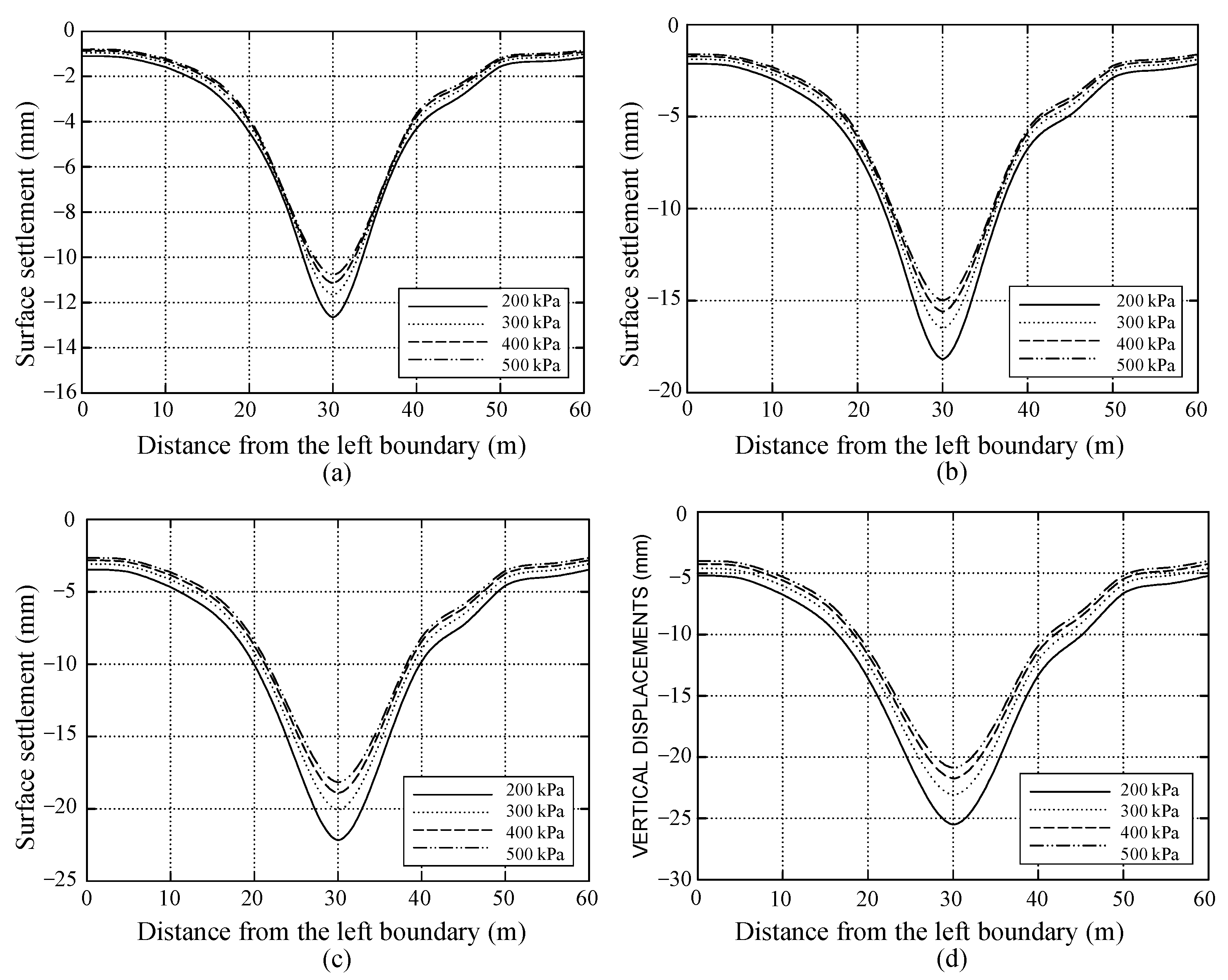
3.2. Influence of Different Burial Depths on the Lubricant Controlling Effect

Figure 7 depicts the model considering various burial depths. Drawing on the existing structure and its pipe-roof arrangement scheme described in the case study (Figure 2), the dimensions and relative positions of the tunnel and steel pipelines were determined. During the simulation, 28 steel pipelines were sequentially jacked following a center-to-sides procedure, while surface displacement induced by pipe-roof construction was monitored along lateral monitoring Line 3. Table 4 outlines the simulation scenario designed to assess the influence of burial depth on lubricant control effectiveness. In Cases 1–1 through 1–4, burial depths were set at 2 m, 4 m, 6 m, and 8 m, respectively. For each case, different lubricant Young’s moduli (ranging from 200 kPa to 500 kPa) were considered, while the Poisson’s ratio was assumed to be 0.4 to minimize the influence of additional variables. All other model settings remain unchanged.
Figure 8 illustrates the transverse settlement trough generated by pipe-roof construction for each case in Scenario 1. Under identical lubricant conditions, as burial depth increases, surface settlement progressively rises, and the settlement curve transitions from a narrow, steep profile to a broad, gentle one. This trend demonstrates that increasing burial depth undermines the lubricant’s capacity to control surface settlement.
Conversely, as Young’s modulus increases from 200 kPa to 500 kPa, the surface settlements in Cases 1–1 through 1–4 diminish; however, the extent of reduction differs among the cases. Specifically, at a burial depth of 2 m, the peak settlement is lowered from approximately 12.6 mm to 11 mm—a decrease of 14.5%. However, at a burial depth of 8 m, the maximum settlement declines from 25.4 mm to 20.7 mm, corresponding to a reduction of 22.7%. These suggest that, with the growth of burial depth, enhancing the lubricant elastic modulus can more significantly augment its control effect; conversely, the benefit of elevating the lubricant stiffness is attenuated. Furthermore, the results indicate that lower-stiffness lubricants consistently produce more pronounced surface displacements. Therefore, for greater burial depths, it is advisable to select a high-stiffness lubricant to reduce the impact of repeated pipe jacking on the ground surface, whereas, for shallower burial depths, a medium-stiffness lubricant is sufficient to inhibit the contraction of the soil layer surrounding the pipe.

3.3. Influence of Arrangement Scheme on the Lubricant Controlling Effect

Based on Case 1–2 in Scenario 1, a horseshoe-shaped system model was constructed as illustrated in Figure 9. To control for variables, the burial depth range of this system was maintained approximately identical to that of the gate-shaped system in Case 1–2. As a result, the horseshoe-shaped pipe roof was configured with a span of 13 m and a crown positioned 4 m below the ground surface, and the number of steel pipelines was accordingly adjusted to 25, while all other settings and parameters remained consistent with those in Case 1–2. Notably, to simplify the modeling process, no tunnel element was included in this section. The resulting simulation data were employed to analyze the impact of pipe-roof arrangement options on the control effectiveness of lubricant on surface settlement.
Table 5 provides detailed information on Scenario 2, while Figure 10 presents the simulation results for this scenario. Figure 10a illustrates the surface displacement of the horseshoe-shaped system along monitoring Line 3 under different lubricant conditions. As the lubricant Young’s modulus increases, the surface displacement progressively decreases, and the settlement curve becomes flatter and shallower. Figure 10b compares the transverse settlement troughs for the two arrangement schemes at a burial depth of 4 m and a Young’s modulus of 400 kPa. By contrast, the settlement curve of the gate-shaped system adopts a V-shaped profile, appearing narrower and steeper, which results in a larger peak settlement. Conversely, the horseshoe-shaped system exhibits a U-shaped settlement curve that is broader and smoother, leading to slightly higher settlement values at the two sides of the crown. To further analyze the cause of this phenomenon, displacement contour maps for both systems are provided, as illustrated in Figure 11. Overall, the gate-shaped arrangement scheme is characterized by a larger disturbance range; however, the resulting soil deformation is predominantly concentrated on the upper side of the pipe roof. In contrast, the horseshoe-shaped arrangement scheme shows a smaller disturbance range, with soil deformation distributed evenly along both sides of the crown. The analysis implies that the horseshoe-shaped system yields a more rational force distribution on the pipe roof and facilitates the uniform transfer of disturbance loads to both sides. In comparison, the gate-shaped pipe roof, resembling a frame structure, subjects its cross-beam element to considerable bending moments, thereby heightening the risk of localized stress concentrations. The findings indicate that the horseshoe-shaped system is more conducive to the control effect of lubricant.
On the other hand, a comparison of Figure 10a and 8b reveals that increasing the Young’s modulus from 200 kPa to 500 kPa decreases the maximum surface settlement by approximately 3 mm for both schemes; however, the reduction amounts to only 16% for the gate-shaped arrangement, while it reaches 20% for the horseshoe-shaped system. Clearly, compared with the gate-shaped system, the pipelines in the horseshoe-shaped arrangement are positioned at varying elevations, and thus a shielding effect exists between each pair of adjacent pipelines. Consequently, elevating the lubricant stiffness exerts a more pronounced improvement effect on this system, thereby more obviously diminishing its surface displacement.

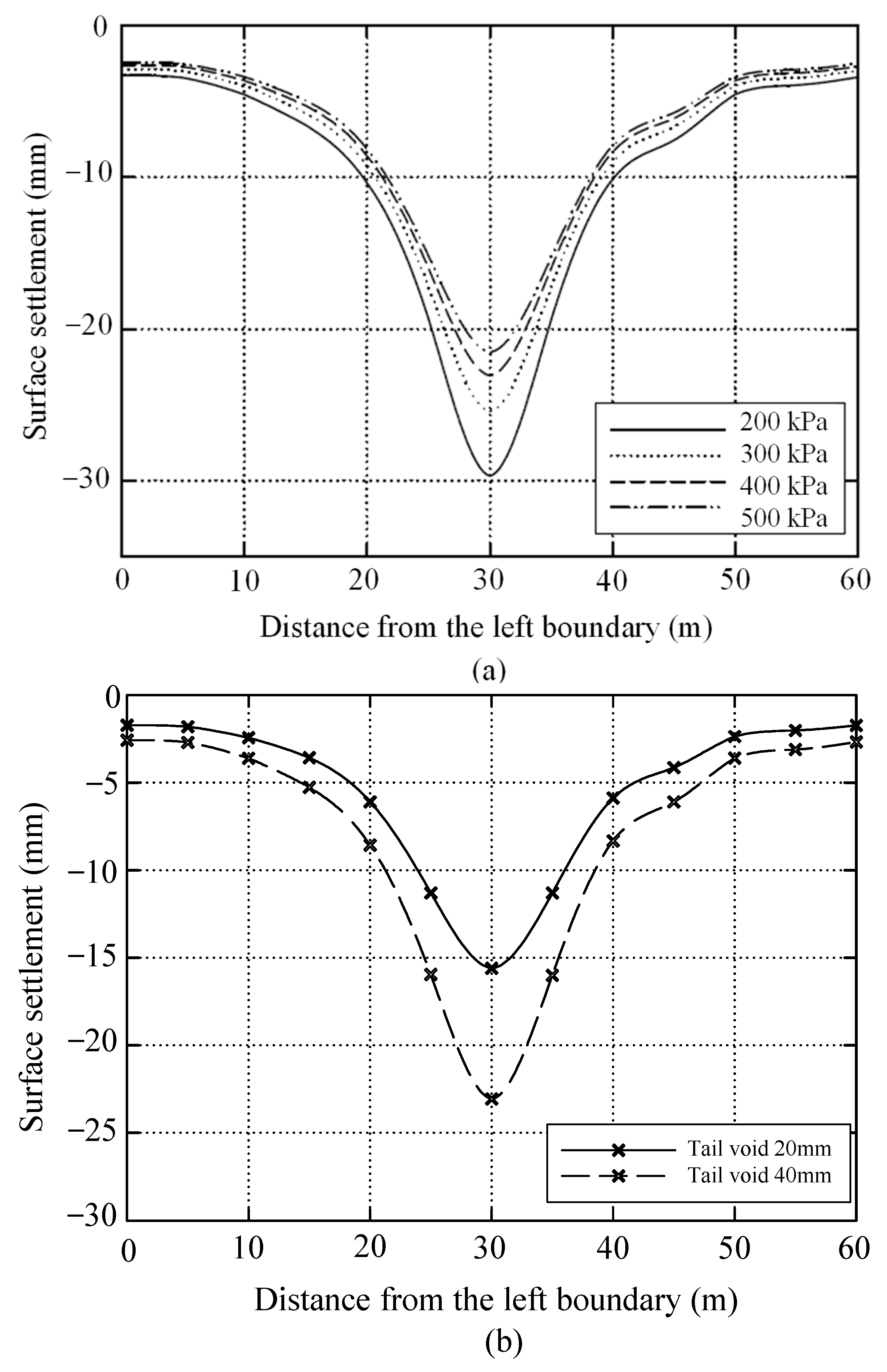
3.4. Influence of Tail Void on the Lubricant Controlling Effect

This section simulated the surface displacement along monitoring Line 3 when the tail void was set to 40 mm. All simulation settings were identical to those in Case 1–2 in Scenario 1, except for the tail void value. Thus, the gate-shaped pipe-roof layout was adopted for the model, with the burial depth fixed at 4 m and the Young’s modulus uniformly increased from 200 kPa to 500 kPa. Refer to Figure 7 for the model used in this section.
Table 6 lists the primary parameters for simulation Scenario 3, and Figure 12 displays the corresponding simulation results. As evidenced in Figure 12, the larger tail void results in greater surface settlement and a steeper settlement trough (Figure 12b); however, surface displacement can be fruitfully controlled by increasing the lubricant Young’s modulus (Figure 12a). Additionally, a comparison of Figure 12a and Figure 8b shows that, when other variables are held constant, raising the lubricant elastic modulus from 200 kPa to 500 kPa lowers the maximum vertical displacement for the tail void of 40 mm from 29.6 mm to 21.5 mm—an approximate reduction of 27%—whereas the reduction for the tail void of 20 mm is 17.6%. The foregoing results indicate that although enlarging the tail void weakens the lubricant’s ability to control surface settlement, it simultaneously enhances the reduction in surface settlement achieved by augmenting the lubricant Young’s modulus.

4. Conclusions

As a vital auxiliary technology for trenchless construction in urban underground spaces, it is imperative to effectively mitigate the surface settlement induced by the pipe-roof method. However, many factors affect the ground response during pipe-roof construction, including the lubricant Young’s modulus, tail void, burial depth, and pipe-roof arrangement. Using the calibrated FLAC3D model, the effects of the lubricant Young’s modulus and its interactions with tail void, burial depth, and pipe-roof arrangement on the surface displacement were investigated. The principal conclusions are as follows:
  • In general, increased surface settlement is observed with greater burial depths and larger tail voids. Moreover, a V-shaped transverse settlement trough, characterized by higher surface displacement, is caused by the gate-shaped system, while a U-shaped transverse settlement trough, associated with lower surface displacement, is induced by the horseshoe-shaped system;
  • Typically, increasing the tail void and burial depth diminishes the lubricant’s ability to control surface settlement, whereas the horseshoe-shaped system is more conducive to effective control (compared with the gate-shaped system). Under these three cases, augmenting the lubricant Young’s modulus can reduce surface settlement to a greater extent;
  • Lubricants manifest their control effect by influencing the interaction among adjacent pipelines. Broadly speaking, increasing the lubricant Young’s modulus more efficiently suppresses the repeated disturbance effect or enhances the shielding effect between each pair of adjacent pipelines, thereby providing better control over the surface settlement induced by pipe-roof construction. This effect is especially pronounced in soft soil layers.

Author Contributions

Methodology, software, validation, and writing—original draft preparation, S.Z.; Conceptualization and supervision, T.S.; data curation, A.H.; project administration, X.H.; writing—review and editing, H.S.; software and validation, P.M. All authors have read and agreed to the published version of the manuscript.

Funding

This research received no external funding.

Institutional Review Board Statement

Not applicable.

Informed Consent Statement

Not applicable.

Data Availability Statement

Some or all data, models, or codes that support the findings of this study are available from the corresponding author (hamanaka@mine.kyushu-u.ac.jp) upon reasonable request.

Acknowledgments

The authors would like to thank the editor for handling this submission and the anonymous referees for reading the manuscript. Additionally, this work was also generously supported by the China Scholarship Council, for which we are deeply grateful.

Conflicts of Interest

The authors declare no conflicts of interest.

References

  1. Sterling, R.L. Developments and research directions in pipe jacking and microtunneling. Undergr. Space 2020, 5, 1–19. [Google Scholar] [CrossRef]
  2. Li, R.; Zhang, D.; Wu, P.; Fang, Q.; Li, A.; Cao, L. Combined Application of Pipe Roof Pre-SUPPORT and Curtain Grouting Pre-Reinforcement in Closely Spaced Large Span Triple Tunnels. Appl. Sci. 2020, 10, 3186. [Google Scholar] [CrossRef]
  3. Hao, Z.; Zhang, H.; Zhang, G.; Xiong, W.; Wang, L. The Prediction of Ground Settlement of a Box Culvert Jacked Under the Action of an Ultra-Shallow Buried Pipe Curtain. Arab. J. Sci. Eng. 2022, 47, 12423–12438. [Google Scholar] [CrossRef]
  4. Zhou, H.; Huang, S.; Zhang, P.; Ma, B.; Ma, P.; Feng, X. Prediction of jacking force using PSO-BPNN and PSO-SVR algorithm in curved pipe roof. Tunn. Undergr. Space Technol. 2023, 138, 105159. [Google Scholar] [CrossRef]
  5. Bai, Q.; Zhao, W.; Cao, W.; Jia, P.; Cheng, C.; Lu, B. Test and Numerical Simulation of Excavation of Subway Stations Using the Small Pipe–Roof–Beam Method. Int. J. Geomech. 2023, 23, 04023018. [Google Scholar] [CrossRef]
  6. He, J.; Liao, S.; Tan, Y.; Liu, M. Analytical Study on the Ground Settlement Induced by Pipe-roof Tunnelling Considering the Interaction between Socketed Pipes. KSCE J. Civ. Eng. 2022, 27, 417–430. [Google Scholar] [CrossRef]
  7. Zhang, P.; Ma, B.; Zeng, C.; Xie, H.; Li, X.; Wang, D. Key techniques for the largest curved pipe jacking roof to date: A case study of Gongbei tunnel. Tunn. Undergr. Space Technol. 2016, 59, 134–145. [Google Scholar] [CrossRef]
  8. Liu, J.; Ma, B.; Cheng, Y. Design of the Gongbei tunnel using a very large cross-section pipe-roof and soil freezing method. Tunn. Undergr. Space Technol. 2018, 72, 28–40. [Google Scholar] [CrossRef]
  9. Feng, J.; Tan, Y.; Zhang, J.; Ma, K.; Dai, Y.; Yao, S. Evolution mechanism of axial force of super-long pipe roof. J. Civ. Struct. Health Monit. 2024, 14, 527–544. [Google Scholar] [CrossRef]
  10. Musso, G. Jacked Pipe Provides Roof for Underground Construction in Busy Urban Area. Civil Eng. 1979, 49, 79–82. [Google Scholar]
  11. Jia, P.; Zhao, W.; Khoshghalb, A.; Ni, P.; Jiang, B.; Chen, Y.; Li, S. A new model to predict ground surface settlement induced by jacked pipes with flanges. Tunn. Undergr. Space Technol. 2020, 98, 103330. [Google Scholar] [CrossRef]
  12. Ma, P.; Shimada, H.; Sasaoka, T.; Hamanaka, A.; Dintwe, T.K.M.; Pan, D. Investigation on the Performance of Pipe Roof Method Adjacent to the Underground Construction. Geotech. Geol. Eng. 2021, 39, 4677–4687. [Google Scholar] [CrossRef]
  13. Yang, S.-S.; Zhang, D.-W.; Wang, M.; Xu, J.-M.; Shen, C.; Zhang, C.-Z. Ground settlement caused by pipe-roof pre-construction method: Effect of the sequence of jacking pipe groups. J. Cent. South Univ. 2024, 31, 576–588. [Google Scholar] [CrossRef]
  14. Tang, Z.; Wang, H.-X.; Sun, D.-A.; Zhang, X. Surface displacement during pipe roof construction of pipe-jacking group with large section. Rock Soil Mech. 2022, 43, 9. [Google Scholar] [CrossRef]
  15. Ma, M.; Han, L.; Wu, Y.; Li, Q.; Zhang, Y. Behavioral Investigations of Three Parallel Large Reinforced Concrete Circular Pipes with the Construction of Pipe Jacking. Appl. Sci. 2023, 13, 8901. [Google Scholar] [CrossRef]
  16. Liu, B.; Jie, J.; Gao, Y.; Tian, X. Study on the Influence of Large Section Rectangular Pipe Jacking Construction on Soil Deformation. In Proceedings of the 2022 8th International Conference on Hydraulic and Civil Engineering: Deep Space Intelligent Development and Utilization Forum (ICHCE), Xi’an, China, 25–27 November 2022; pp. 773–776. [Google Scholar]
  17. Maehara, K.; Shimada, H.; Sasaoka, T.; Hamanaka, A. Development of Filling Material with Fly Ash and Slag as Lubricant in Pipe Jacking Under Acid Sulfate Soils. In Proceedings of the International Conference on Environment and Mineral Processing (EAMP), Ostrava, Czech Republic, 30 May–1 June 2019; pp. 115–119. [Google Scholar]
  18. Shimada, H.; Khazaei, S.; Kikuo, M. Small diameter tunnel excavation method using slurry pipe-jacking. Geotech. Geol. Eng. 2004, 22, 161–186. [Google Scholar]
  19. Zhou, S.; Wang, Y.; Huang, X. Experimental study on the effect of injecting slurry inside a jacking pipe tunnel in silt stratum. Tunn. Undergr. Space Technol. 2009, 24, 466–471. [Google Scholar] [CrossRef]
  20. Liu, S.; Zhang, B.; Zhang, X.; Fan, D.; Wang, H.; Yu, M. Formulation optimization and performance analysis of the thixotropic slurry for large-section rectangular pipe jacking in anhydrous sand. Constr. Build. Mater. 2022, 357, 129380. [Google Scholar] [CrossRef]
  21. Li, M.; Yang, J.; Zeng, L.; Jin, J.; Liu, Y. Case Study on the Interaction Between Rectangular Pipe Jacking Control and Ground Settlement in Silty Clay. Int. J. Civ. Eng. 2023, 21, 1447–1462. [Google Scholar] [CrossRef]
  22. Liu, J.; Cheng, H.; Cai, H.; Wang, X.; Feng, D. Design and Analysis of Grouting Pressure in Slurry Pipe Jacking Based on the Surrounding Soil Stability Mechanical Characteristics. Geofluids 2022, 2022, 1–17. [Google Scholar] [CrossRef]
  23. Qian, D.; Jiao, H.; Li, Z.; Zhu, Y.; Liu, J.; Chen, Z.; Gao, X.; Liu, H.; Tao, B.; Xu, Z. Ground Settlement Law, Jacking Force Prediction, and Control Countermeasures for Large-Section Rectangular Pipe Jacking of National Highway Underpass. Sustainability 2023, 15, 2888. [Google Scholar] [CrossRef]
  24. She, F.; Wu, Z.; Zhou, W.; Liu, G.; Li, L. Deformation control of surrounding rock of rectangular pipe-jacking tunnels considering key construction parameters Chin. J. Geotech. Eng. 2022, 44, 247–253. [Google Scholar]
  25. Kong, C.; Guan, G.; Gu, S.; Zhou, Z.; Wang, H. Frictional resistance calculation and jacking force prediction of rectangular pipe jacking. Sci. Rep. 2023, 13, 14992. [Google Scholar] [CrossRef]
  26. Jia, P.; Jiao, C.; Zhang, W. Numerical Estimation on Jacking Force and Resistance Relieving Effect of Large Diameter Pipe Jacking in Shenyang. J. Northeast. Univ. Nat. Sci. 2013, 34, 1206–1209. [Google Scholar]
  27. Deng, M.; Ding, F.; Liu, Y.; Huang, X.; He, Y.; Zhao, J. Surface settlement law of double-hole pipe-jacking tunnel undercrossing expressway. Sci. Rep. 2023, 13, 19286. [Google Scholar] [CrossRef]
  28. Li, H.; Yang, Y.; Tu, X.; Wang, T. Analysis of jacking force for rectangular pipe jacking machine. Prz. Elektrotechniczny 2012, 88, 200–203. [Google Scholar]
  29. Yen, J.; Shou, K. Numerical simulation for the estimation the jacking force of pipe jacking. Tunn. Undergr. Space Technol. 2015, 49, 218–229. [Google Scholar]
  30. Khazaei, S.; Shimada, H.; Matsui, K. Analysis and prediction of thrust in using slurry pipe jacking method. Tunn. Undergr. Space Technol. 2004, 19, 356. [Google Scholar]
  31. You, G. 3D FEM analysis on ground displacement induced by curved pipe-jacking construction. In Geotechnical Aspects of Underground Construction in Soft Ground; CRC Press: Boca Raton, FL, USA, 2008; pp. 759–764. [Google Scholar]
Figure 1. The case location and detection plan layout.
Applsci 15 03713 g001
Figure 2. The detailed parameters of the validated case.
Applsci 15 03713 g002
Figure 3. Verification model and its size parameters.
Applsci 15 03713 g003
Figure 4. Surface settlement from simulation and monitoring results: (a) comparison of surface settlement between simulation results and measured data at monitoring Line 1; (b) comparison of surface settlement between simulation results and measured data at monitoring Line 2.
Applsci 15 03713 g004
Figure 5. Surface settlement values from monitoring point O under different Young’s modulus conditions and their comparison with measured results.
Applsci 15 03713 g005
Figure 6. Transverse settlement troughs obtained after the sequential jacking of each steel pipeline at monitoring Line 1.
Applsci 15 03713 g006
Figure 7. Schematic diagram of the model considering different burial depths.
Applsci 15 03713 g007
Figure 8. Influence of burial depths on the effectiveness of lubricants in controlling pipe-roof-induced settlement: (a) Case 1–1, h = 2 m; (b) Case 1–2, h = 4 m; (c) Case 1–3, h = 6 m; (d) Case 1–4, h = 8 m.
Applsci 15 03713 g008
Figure 9. Horseshoe-shaped system arrangement of pipe roof.
Applsci 15 03713 g009
Figure 10. Vertical displacement of the ground surface: (a) changes in ground settlement of horseshoe-shaped system considering different lubricants (Line 3): (b) comparison of surface settlement between the two systems when h = 4 m, E = 400 kPa, and tail void = 20 mm.
Applsci 15 03713 g010
Figure 11. Ground displacement contour maps of different pipe-roof layout schemes: (a) simulation results of Case 1–2 in Scenario 1; (b) simulation results of Case 2–1 to Case 2–4 in Scenario 2.
Applsci 15 03713 g011
Figure 12. Vertical displacement of the ground surface: (a) changes in ground settlement of 40 mm tail void considering different lubricants (Line 3): (b) comparison of surface settlement between the two tail voids when h = 4 m, E = 400 kPa in gate-shaped system.
Applsci 15 03713 g012
Table 1. The soil mechanical properties in the study case.
SoilYoung’s Modulus (MPa)Poisson’s RatioFriction Angle (°)Cohesion (MPa)Density (kg/m3)
Gravelly clay19.40.420.70.0582000
Clay16.90.3511.70.0421830
Table 2. Lubricant mechanical parameters considering consolidation.
VariablesConsolidation TimeYoung’s Modulus (MPa)Poisson’s RatioDensity (kg/m3)Thickness (mm)Components
Lubricant used on-siteAfter injection0.10.49210020Silicate minerals + Polymers + Fibers
7 days0.230.4
14 days0.320.4
21 days0.370.4
28 days0.400.4
Table 3. Mechanical parameters of concrete and steel pipe.
TypeYoung’s Modulus (MPa)Poisson’s RatioDensity (kg/m3)Thickness (mm)
Concrete22,0000.22400-
Steel pipe210,0000.25210,00012
Table 4. Modeling scenario to study the effect of burial depth on lubricant control effectiveness.
Modeling ScenariosModeling CasesBurial Depth h (m)Lubricant Input ParametersPipe Roof Arrangement Tail Void (mm)
Young’s Modulus (kPa) Poisson’s Ratio Density (kg/m3)
Scenario 1Case 1–12200, 300, 400, 5000.42100Gate-shaped system (28 pipelines)20
Case 1–24
Case 1–36
Case 1–48
Table 5. Modeling scenario considering pipe-roof arrangement.
Modeling ScenariosModeling CasesBurial Depth h (m)Lubricant Input ParametersPipe Roof ArrangementTail Void (mm)
Young’s Modulus (kPa)Poisson’s RatioDensity (kg/m3)
Scenario 2Case 2–142000.42100Horseshoe-shaped system (25 pipelines)20
Case 2–2300
Case 2–3400
Case 2–4500
Table 6. Modeling scenario considering tail void.
Modeling ScenariosModeling CasesBurial Depth h (m)Lubricant Input ParametersPipe Roof ArrangementTail Void (mm)
Young’s Modulus (kPa)Poisson’s RatioDensity (kg/m3)
Scenario 3Case 3–142000.42100Gate-shaped system (28 pipelines)40
Case 3–2300
Case 3–3400
Case 3–4500
Disclaimer/Publisher’s Note: The statements, opinions and data contained in all publications are solely those of the individual author(s) and contributor(s) and not of MDPI and/or the editor(s). MDPI and/or the editor(s) disclaim responsibility for any injury to people or property resulting from any ideas, methods, instructions or products referred to in the content.

