Article

Rotor Unbalanced Vibration Control of Active Magnetic Bearing High-Speed Motor via Adaptive Fuzzy Controller Based on Switching Notch Filter

1
School of Electrical and Control Engineering, Shaanxi University of Science & Technology, Xi’an 710021, China
2
School of Automation, Northwestern Polytechnical University, Xi’an 710129, China
*
Author to whom correspondence should be addressed.
Appl. Sci. 2025, 15(7), 3681; https://doi.org/10.3390/app15073681
Submission received: 18 February 2025 / Revised: 22 March 2025 / Accepted: 24 March 2025 / Published: 27 March 2025

Abstract

:
This paper proposes an adaptive fuzzy controller based on a switching notch filter to address the rotor unbalance vibration control problem of an active magnetic bearing (AMB) high-speed motor system in the full rotational speed range. Aiming at the complex nonlinear and time-varying characteristics of the AMB rigid rotor system, this study designs an adaptive fuzzy controller (AFC) that obtains fuzzy quantities by blurring the rotor vibration information and vibration rate of change as the input signals and then obtains the fuzzy set through fuzzy reasoning and modifies the parameters of the initial fuzzy controller. The initial fuzzy controller parameters are modified through fuzzy reasoning to improve the control effect and ensure the stable suspension of the rotor during high-speed rotation. At the same time, in order to effectively suppress the vibration of the rotor in high-speed operation due to unbalance and other factors, this paper introduces an adapting notch filter (ANF) as a vibration control strategy on the basis of AFC, and the notch filter is able to monitor the rotor vibration signals and adaptively adjust the center frequency and bandwidth. Finally, the correctness and effectiveness of the adaptive fuzzy controller based on a switching notch filter (AFC-ANF) are verified via simulations and experiments. The simulation results demonstrate that compared to traditional PID control, the AFC reduces the response time by 0.11 s. Under constant-speed operating conditions, the AFC-ANF strategy decreases rotor vibration by 60%, while under variable-speed conditions, it reduces rotor vibration displacement by 40%, showcasing significant vibration suppression effectiveness. This research provides a novel solution for vibration control in magnetic bearing systems, offering both important theoretical significance and practical application value.

1. Introduction

As an advanced bearing technology, active magnetic bearings (AMBs) are widely used in high-speed rotating machines, such as high-speed motors, flywheel energy storage systems, centrifugal pumps, and other high-speed rotating machines due to their significant advantages of being contactless and frictionless and having high precision and a long life [1,2,3]. The AMB system is a typical electromechanical coupled system with complex dynamic characteristics, strong nonlinearities, and parameter uncertainties. During the operation of high-speed AMB motors, significant vibrations are generated due to factors such as rotor imbalance and external disturbances, particularly during high-speed and acceleration phases. These vibrations not only degrade the motor’s performance but may also lead to system instability or damage. Therefore, it is necessary to maximize system stability and control rotor vibration. Currently, fuzzy control [4,5,6], as a modern control strategy, does not rely on precise mathematical models, and it has good intelligence and robustness for both linear and nonlinear systems [7,8,9,10]. Fuzzy control, as a control method that combines fuzzy control with classical PID control algorithms, significantly improves the system’s dynamic responsiveness and operational stability by virtue of its intelligence and robustness. Ren [11] proposed a model based on a fuzzy controller for active electromagnetic bearings to achieve fast and stable levitation. Tang [12] proposed a fuzzy adaptive control strategy to improve rotor speed recovery. Ma [8] proposed a filter-based fuzzy adaptive control scheme to improve the convergence and stability of the system. Jiang [13] proposed a suspension control strategy based on adaptive nonsingular terminal sliding mode control. By integrating adaptive control with terminal sliding mode control, this strategy effectively reduces system chattering and significantly enhances the dynamic performance of the suspension system. AFC is capable of handling nonlinear systems and does not rely on precise mathematical models. The dynamic characteristics of AMB systems are complex and highly nonlinear, making traditional PID control inadequate to meet the systems’ requirements. In contrast, the AFC dynamically adjusts control parameters in real time through fuzzy rules, effectively addressing the nonlinear characteristics of the system.
In general, in order to ensure the stability of the system, it is also necessary to suppress the vibration of the rotor due to unbalance and other factors in high-speed operation. The ANF is capable of monitoring rotor vibration signals in real time and adjusting the center frequency and bandwidth based on changes in rotational speed, effectively suppressing vibration components that are synchronous with the rotational frequency. Ren [14] addresses the problem of the rotor unbalanced vibration of active magnetic bearings by estimating the rotational speed via the bi-directional filtering of noise and generating synchronized signals to eliminate the periodic unbalance effect. Ye [15] improves the vibration suppression performance of magnetic bearings. An adaptive trap based on the minimum mean square error is used to extract vibration signals from rotor displacement signals. Gong [16] proposed a variable-angle compensation algorithm based on an adaptive notch filter to suppress synchronous unbalance vibration in finite iterative searches in an AMB rigid rotor system. This algorithm directly achieves unbalance compensation based on real-time rotor positions. Yu [17] proposes a speed-adaptive trap-based phase-locked loop for sensorless permanent magnet synchronous motors to suppress fluctuations induced by mid-frequency harmonics that is robust to perturbations in the full frequency range. For a magnetically levitated centrifugal compressor, Zhang [18] proposed the use of a conventional trap to eliminate the same-frequency perturbation in the glitch signal and to use an improved adaptive trap method to estimate the frequency of the glitch signal, showing that the system gradually stabilized. Ma [19] designed an adaptive trap for vibration monitoring with an active magnetic levitation bearing condition detection capability that can accurately extract the vibration fundamental wave components, and the convergence of the modified trap is independent of frequency and replication, obtaining higher estimation accuracy and fast monitoring across the whole speed range. Peng [20] employs a two-stage trap to achieve the suppression of same-frequency vibrations by polarity-switching in the low-speed and high-speed zones of the rotor system. Borque [21] analyzed, in depth, the effectiveness of traps on the channel vibration control of rotor systems during high- and low-speed switching zones. Gong [22] proposed the vibration suppression method of the polarity switching tracking filter and the disturbance observer for the unbalanced vibration of the high-speed motor rotor. Zhong [23] proposed a general model of the magnetically suspended flexible rotor under base motion, considering the rotor shrinkage fit and AMB sensor/actuator not being collocated, based on the finite element method and Lagrange’s equation.
Aiming at the vibration control problem of the AMB rigid rotor system, this study investigates a control strategy that integrates the AFC and ANF to achieve vibration control for high-speed AMB motors across the full rotational speed range, ensuring systemic stability and efficiency. The innovation of this study is primarily reflected in the following two aspects: First, to address the radial vibration component produced by unbalanced forces during the high-speed rotor operation, which is synchronous with the rotational speed, the ANF was designed. With the real-time monitoring of the rotor vibration signals and the adaptive adjustment of the center frequency and bandwidth, the ANF effectively suppresses vibrations in the high-speed region, thereby enhancing the system’s stability. Second, considering the varying closed-loop stability conditions of the magnetic levitation rigid rotor system when operating near the radial rigid critical speed, a control strategy based on polarity switching combined with the adaptive notch filter was proposed. This strategy, integrated with the AFC, ensures the stable operation of the AMB high-speed rigid rotor system across the full speed range, including the rigid critical speed.
This study first processes the rotor vibration information through a fuzzy controller to optimize the control effect. Subsequently, the stability theory is employed to analyze the radial stability of the rotor system after incorporating the automatic balancing control based on the adaptive notch filter. The stability of the rotor system across the full speed range, including the rigid critical speed, is ensured by the polarity-switching strategy. Finally, the effectiveness of the method is verified through simulations and experiments. The structure of this paper is as follows: Section 1 introduces the research background and the problem, Section 2 establishes the dynamic model of the AMB rigid rotor system, Section 3 elaborates on the adaptive notch filter control strategy based on fuzzy control, Section 4 verifies the effectiveness of the control strategy through simulation, Section 5 further validates the practical application effect of the method through experiments, and Section 6 summarizes the full text and proposes future research directions.

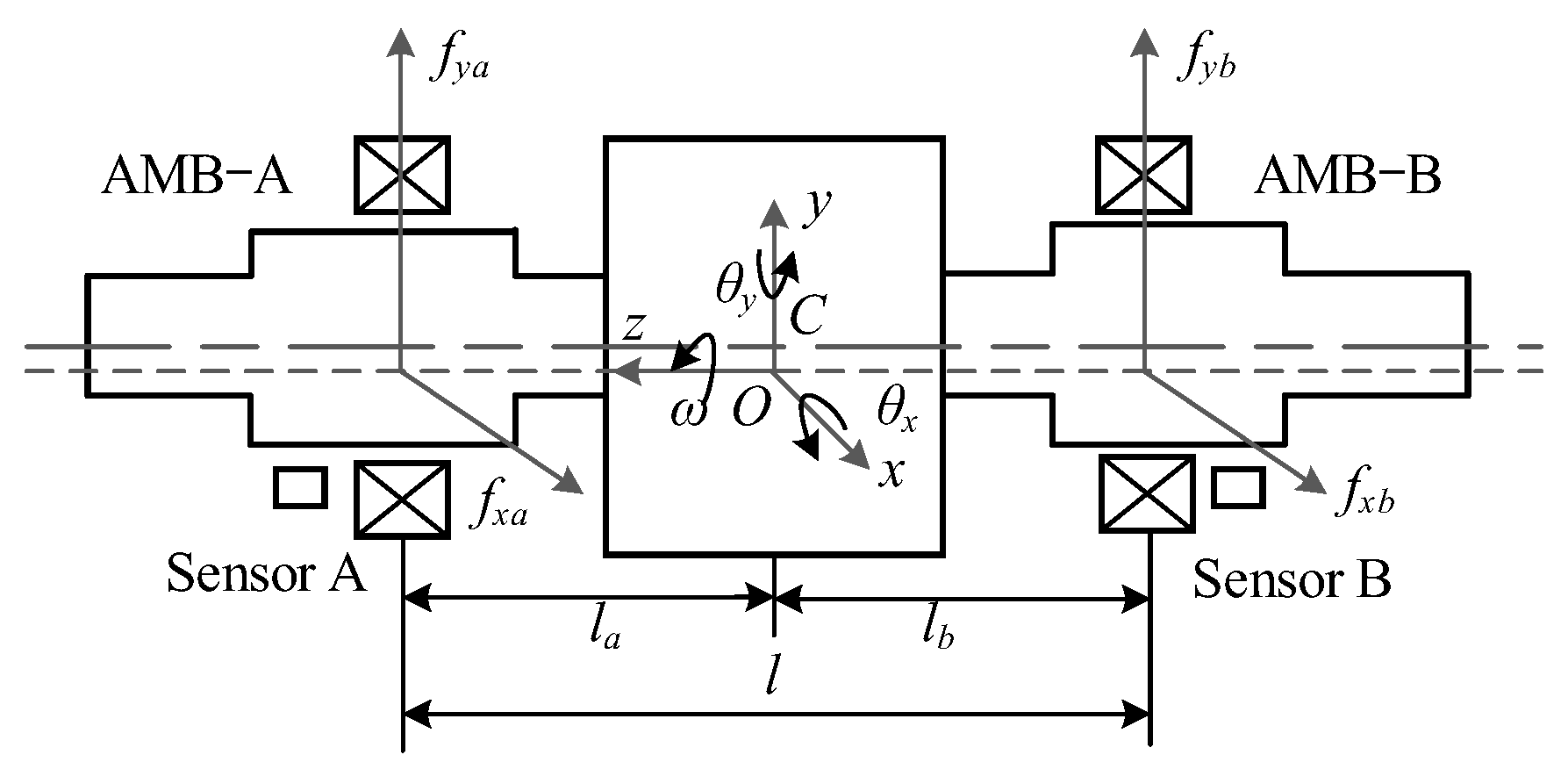
2. Dynamical Mode of AMB Rigid Rotor System During Accelerated Motion

The structure of the AMB rigid rotor system proposed in this study is shown in Figure 1. The axisymmetric rotor is supported axially by AMBs. In order to describe the kinematic state of the AMB rotor system, the relevant planes and coordinate systems are also defined in Figure 1. It is assumed that the center planes of AMB-A and AMB-B are ΠA and ΠB, respectively. The center of mass of the unbalanced rotor is C. Due to symmetry, point C is located on the geometric centerline of the rotor. The distances from point O to the planes ΠA and ΠB are la and lb, respectively, and the distance between planes ΠA and ΠB is l. A fixed coordinate system Oxyz is established, where the z axis is the axis of rotation, and a right-handed system is formed between x, y, and z. Then, the motion state of the rotor can be described by (x, y, θx, θy).
For an unbalanced rotor, the unbalance of the rotor is equivalently generated by an additional unbalanced mass that is not at the center of mass C of the balanced rotor. Assuming that the unbalanced mass of the additional rotor is at the point position, the projection in the plane of the geometric center of the balanced rotor is ɛz, the length of the projection on the OZ axis is ɛz, and the eccentricity distance from point to point is ɛ. In order to describe the motion of the rotor geometric center, the Cxryr rotating coordinate system is established with C as the origin, when the Cxr axis of the rotating coordinate system Cxryr is parallel to the Ox axis, where the transient rotation angle of G is ϕ. As shown in Figure 2, when the rotor is running steadily, ϕ ˙ = ω and ϕ = ω t .
Using the theory of rotor dynamics and considering the effects of rotor unbalance and rotor acceleration, the matrix equation of the AMB rigid rotor system during the accelerated operation is as follows:
M q ¨ + G q ˙ = L f F A M B + F u ,
where M and G are the generalized mass matrix and gyro matrix of the rotor system, respectively, Lf and Fu are the force arm coefficient matrix of the rotor system and the generalized imbalance vector applied to the system, respectively, and FAMB is the vector of electromagnetic forces generated by the radial AMBs at the A/B end in the x and y directions.
During acceleration, the rapid changes in speed and force can increase systemic instability, particularly in the presence of rotor imbalance-induced vibrations. These vibrations may be further amplified during acceleration, potentially leading to systemic instability or even failure. Based on these facts, a dynamic model of the AMB rigid rotor system for accelerating conditions is established. The aim of this study is to address the suppression of imbalance-induced vibrations during acceleration through theoretical analysis and control strategy design, providing theoretical support for the stable operation of the system.

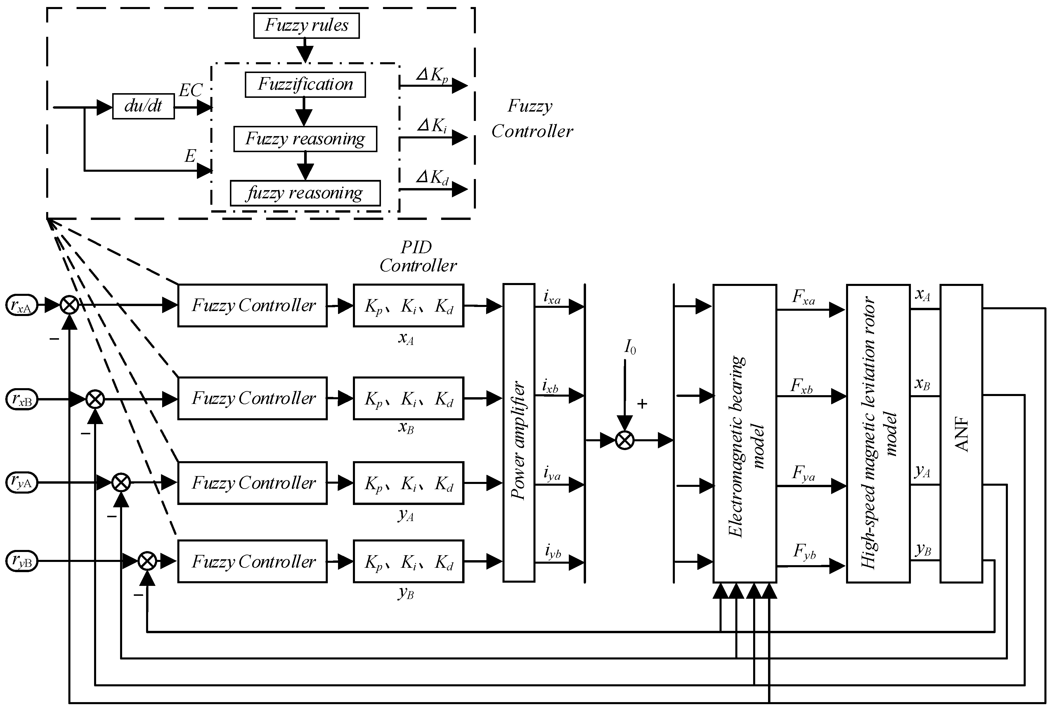
3. AMB Rigid Rotor System Based on Fuzzy Control Strategy

The dynamic performance of AMBs exhibits strong nonlinearity. During the high-speed operation of AMB motors, the vibration frequency varies with the rotational speed, making traditional fixed-parameter control methods inadequate to adapt to these dynamic changes. However, the AFC strategy can adjust parameters in real time to accommodate changes in the rotational speed, optimizing the system’s dynamic response, thereby enhancing systemic stability.
The AMB high-speed rigid rotor system itself is an unstable strong nonlinear system, and its mathematical model is not easy to accurately obtain; thus, when fuzzy control is used as a classical nonlinear control method, the combination of the traditional PID control and fuzzy control is utilized to achieve the fuzzy adaptive PID control of vibrations of a AMB high-speed rigid rotor system. In the control system depicted in Figure 3, the fuzzy PID controller structure is based on the traditional PID control, with the fuzzy controller correcting the proportional, integral, and derivative systems to achieve the goal of cooperative control. The schematic diagram illustrating the structure of fuzzy PID control is provided in Figure 3. Typically, the implementation of fuzzy control mainly includes fuzzification, knowledge base, logical judgment, and defuzzification. Its working principle is as follows: the filtered rotor vibration displacement signal is compared with the reference displacement signal to generate the error signal and its rate of change, which serve as the input variables for the fuzzy controller. Based on a predefined fuzzy rule base, the fuzzy controller performs fuzzification, rule evaluation, and defuzzification using the Mamdani inference method to generate a continuous control signal. This control signal acts on the rigid rotor system, driving the system output to track the reference signal. Throughout the control process, the fuzzy controller dynamically adjusts the amplitude and direction of the control signal to achieve robust control against the system’s nonlinear characteristics and external disturbances. Simultaneously, the notch filter effectively suppresses periodic interference components, further enhancing the system’s control accuracy and stability.
The design of the fuzzy PID control in the AMB rigid rotor system is shown in Figure 3. Due to its four-degree-of-freedom AMBs and rotor model of internal coupling, the four fuzzy control rules are the same as those of four-degree-of-freedom AMBs.
Using a dual-input and three-output fuzzy controller, the PID control parameters are corrected according to the different variations in the error E and its derivative EC, and the updated values are replaced by the former PID parameter values; then, the updated formula is calculated as follows:
K p = K p 0 + Δ K p K i = K i 0 + Δ K i K d = K d 0 + Δ K d ,
The parameters Kp, Ki, and Kd are the actual parameters of the controller; Kp0, Ki0, and Kd0 are the PID preset tuning parameters; ΔKp is the proportional coefficient correction; ΔKi is the integral coefficient correction; and ΔKd is the differential coefficient correction.

3.1. Defining the Input and Output Variables of the Fuzzy Controller

The fuzzy subsets of the input and output variables of the fuzzy control system are defined as seven fuzzy subsets: PB (positive large), PM (positive medium), PS (positive small), ZO (zero), NS (negative small), NM (negative medium), and NB (negative large).

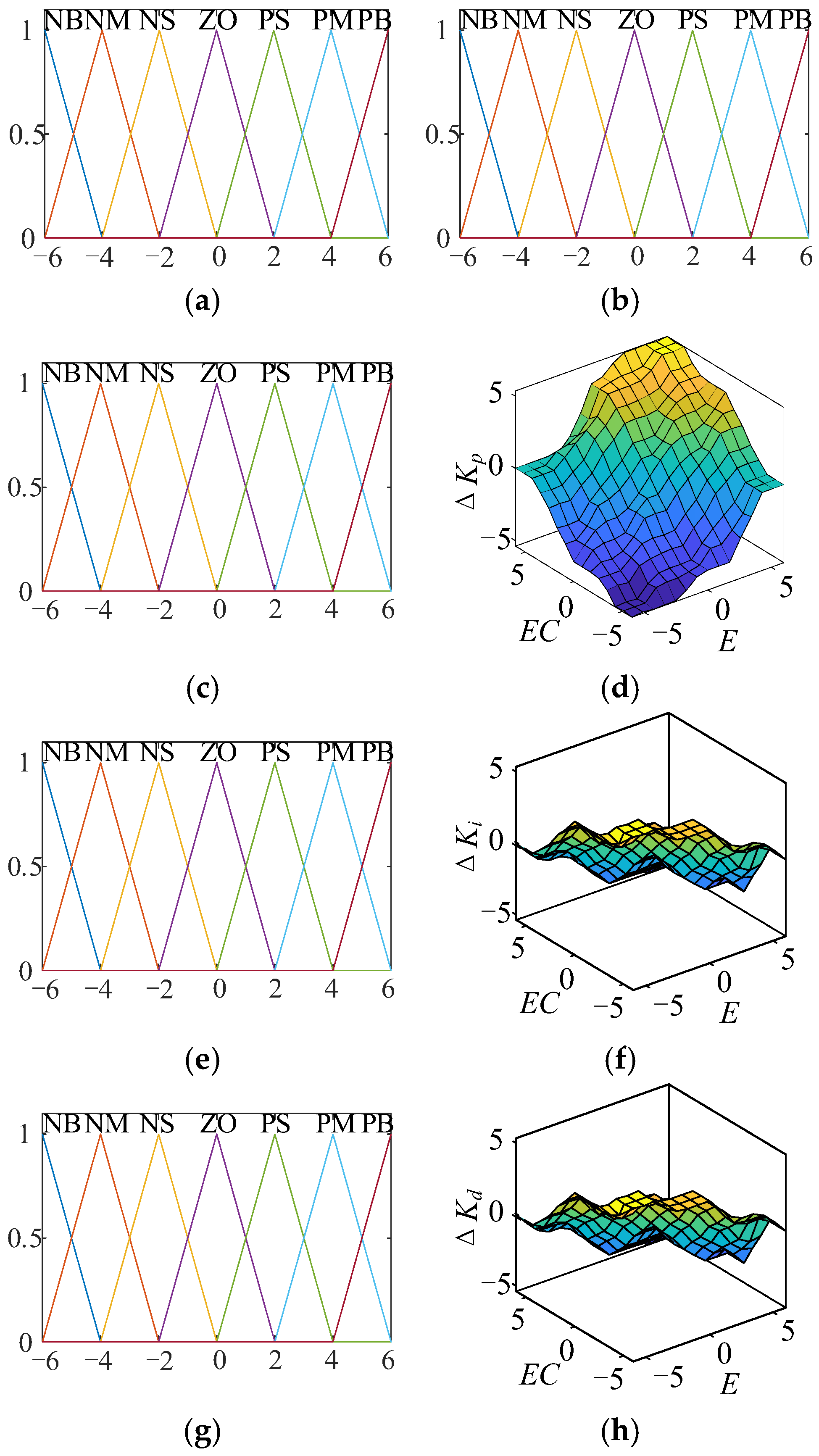
3.2. Defining the Fuzzy Controller Affiliation Function

The membership function is a function used to convert precise numerical values into fuzzy subsets, representing the transition between belonging and not belonging to a set. The definition and selection of membership functions have a significant impact on the performance of fuzzy control systems. Common membership functions include triangular, trapezoidal, and Gaussian membership functions. The triangular membership function is computationally efficient, making it suitable for real-time control systems, and its narrow transition region is particularly well suited for applications requiring a rapid response. The Gaussian membership function offers smooth transitions, making it ideal for high-precision control; however, its higher computational complexity results in reduced real-time performance. The trapezoidal membership function features a broader transition region, making it appropriate for systems that require smooth transitions. Since the error variation in the AMB rotor system is relatively small, triangular membership functions are adopted for both input variables E and EC. The triangular subordination function is expressed as follows:
μ A ( x ) = 0 ,   x a x a b a ,   a < x b c x c b ,   b < x c 0   ,   x > c ,
where a, b, and c are the left, peak, and right endpoints of the triangle, respectively.
The fuzzy domains of the input variables E and EC are set to [−6, 6], and the fuzzy domains of the output variables ΔKp, ΔKi, and ΔKd are also set to [−6, 6]. Figure 4a–h illustrates the triangular membership functions of the input and output variables, along with their corresponding characteristic surface plots.

3.3. Defining a Fuzzy Knowledge Base for Fuzzy Controllers

The fuzzy knowledge base includes a database and a rule base. The database contains quantization factors, affiliation functions, etc., and the rule base is based on expert experience. Suitable fuzzy control rules determine the control performance of the AMB rigid rotor system. There are 7 subsets of both input and output variables, which results in 49 conditional statements to be created in the rule base. The detailed fuzzy rules are provided in the Appendix A.

3.4. Fuzzy Inference and Defuzzification of Fuzzy Controllers

The Mamdani inference type is used, and the value obtained by this method cannot be calculated directly as a specific value; thus, it is necessary to defuzzify the obtained value and process it using the common method of clearing the center of gravity so that the obtained value is the specific value of the output coefficients to be rectified.
The fuzzy controller generates fuzzy outputs based on the input variables (error E and rate of change of error EC). For instance, for the proportional coefficient correction ΔKp, a specific rule in the fuzzy rule base may produce the following fuzzy output:
Δ K p = ( u 1 , μ 1 ) , ( u 2 , μ 2 ) , , ( u n , μ n ) ,
where ui is the possible value of ΔKp, and μi is the membership degree corresponding to ui.
The centroid method determines the specific output value by calculating the weighted average of the fuzzy set. Its mathematical expression is as follows:
u = i = 1 n μ i u i i = 1 n μ i ,
where u* is the specific output value after deblurring (such as the specific value of ΔKp), μi is the membership degree of the i-th output value, and ui is the i-th output value. The calculated u* is used as the correction value to adjust the parameters of the PID controller, as shown in Equation (2), K p = K p 0 + Δ K p .
By reasonably designing the membership functions and optimizing the calculation methods, the centroid method can effectively support the high-performance operation of the control system. In the AMB rigid rotor system, the centroid method ensures the dynamic adjustment of PID parameters, thereby improving the control accuracy and stability of the system.

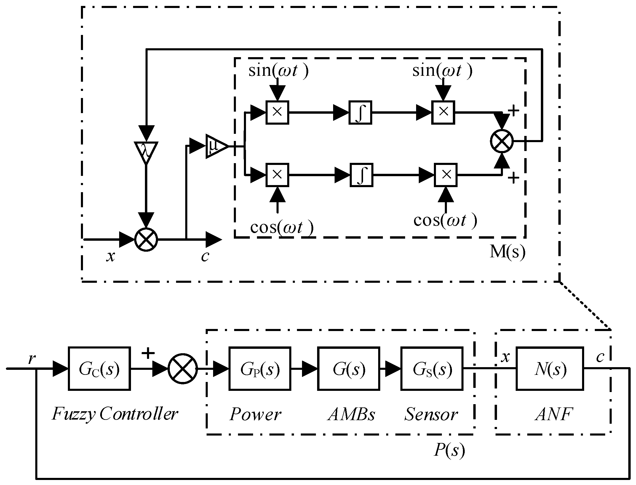
4. Switching Adaptive Notch Filter Vibration Control Strategy Based on Fuzzy Control

In high-speed AMB rigid rotor systems, imbalance-induced vibrations are one of the primary factors affecting systemic stability and performance. Traditional control methods often struggle to effectively suppress vibrations across the full rotational speed range, especially when the rotor passes through the rigid critical speed, where the system’s dynamic characteristics undergo significant changes, leading to reduced control performance. To address this issue, this study proposes a polarity-switching adaptive notch filter control strategy based on fuzzy control. This strategy combines the advantages of the AFC and the ANF, achieving the precise suppression of rotor imbalance-induced vibrations by dynamically adjusting control parameters and filter characteristics in real time.

4.1. Bipolar Filter

In terms of the control strategy of the AMB rigid rotor system, the main controller adopts fuzzy control and adjusts the control parameters according to the real-time monitoring of rotor position information so that the rotor system can respond quickly and operate stably. Secondly, an ANF is added to the input of the fuzzy controller to filter out the signal of the rotor vibration signal measured by the sensor that is at the same frequency as the rotational frequency, which effectively improves the vibration force static dynamic performance of the AMB rigid rotor system but lacks the analysis of the vibration force suppression dynamic performance. However, by switching the symbols of the notch filter gain λ before and after the critical rotational speed, or compensating the phases of the notch filter, the system’s stability can be largely improved.
The equivalent block diagram of the adaptive ANF automatic balancing control is shown in Figure 5.
When λ = 1 , the transfer function N(s) of the ANF is expressed as follows:
N ( s ) = C ( s ) E ( s ) = s 2 + ω 2 s 2 + μ s + ω 2 ,
where μ is the tunable parameter of the ANF, which determines the convergence speed and frequency bandwidth. The closed-loop characteristic equation of the rotor system is shown as follows:
λ M ( s ) G c ( s ) P ( s ) = 0 ,
where λ is the switching factor, M(s) is the concave feedback link, Gc(s) is the controller, Gp(s) is the power amplifier, G(s) is the AMB rigid rotor system transfer function, and Gs(s) is the displacement sensor.
When λ = −1, the transfer function N s is different from N(s). N s is expressed as follows:
N ( s ) = s 2 + ω 2 s 2 μ s + ω 2 ,
In the above analysis, it is evident that the closed-loop system is stable when λ = 1 ; this means that the operation speed is higher than the critical speed of the rigid body. When λ = 1 , the operation speed is lower than the critical speed of the rigid body of the rotor system. Therefore, the automatic switching control of the rotor system should be performed in the full range of rotational speeds of the ANF. The specific switching strategy is to define λ = 1 when the rotor operation speed is lower than its rigid critical speed and to define λ = 1 when the rotor operation speed is higher than its rigid critical speed.

4.2. Fuzzy Control Based on Adaptive ANF

Compared to traditional notch filters, the adaptive bipolar notch filter offers the following two advantages:
(1)
It is possible to simultaneously take into account the rotor unbalanced vibration control of AMB rigid rotor systems in the presence of rigid body translational modes and rigid body conical modes;
(2)
By avoiding the design of an interference observer and controlling the polarity switching, transient vibrations produced during the switching instant can be effectively reduced.
The fuzzy control of adaptive ANF for AMB high-speed motors with rigid rotor systems includes the following steps: Firstly, the input variables of the fuzzy controller are determined to be the error E between the rotor vibration signal xA collected by the eddy current displacement sensor and the reference position rxA, as well as its rate of change R, while the output variable is the power amplifier control signal U. Secondly, the variation range of rotor vibration displacement is ±0.3 mm, and the corresponding variation range of eddy current displacement sensor output voltage is 6 V; thus, the basic domain of xA is chosen to be [−0.003, 0.003], and at this time, the corresponding quantization factor is k1 = 2000. The fundamental domain of the rotor vibration rate of change is [−0.003, 0.003], and its corresponding quantization factor is k2 = 2000. The output variable is the amplifier current, and its fuzzy variable thesis domain is selected as [−6, 6]; then, the fuzzy control rules are formulated. When the rotor vibration xA is much smaller than the reference position rxA, the corresponding error signal E is PB, and the control variable corresponds to the maximum value in order to ensure that the rotor position is rapidly approaching the reference position. When the rotor vibration xA is much larger than the reference position rxA, the control variable corresponds to the minimum value. As the rotor vibration decreases, the vibration error signal E is PS. To ensure that the rotor can run stably, the output should not be too large; thus, the output variable is PS. Finally, taking the fuzzy rules of ΔKp as an example, a Mamdani inference-based fuzzy controller is employed. For instance, if the fuzzy quantities of rotor vibration error E and its rate of change R are 3 and −3, respectively, it can be inferred from Figure 4c that E and EC belong to (PS and PM) and (NM and NS), respectively. Therefore, based on the Appendix A, the fuzzy rules for ΔKp are as follows:
Rule 1: if E is PS and R are NM, then U1 is PS.
Rule 2: if E is PS and R are NS, then U2 is ZO.
Rule 3: if E is PM and R are NM, then U3 is ZO.
Rule 4: if E is PM and R are NS, then U4 is ZS.
Using Mamdani’s criterion, the fuzzy value U1 of U is calculated as follows:
U 1 = ρ 1 ( U ) ρ 2 ( U ) ρ 3 ( U ) ρ 4 ( U ) ,
where ρ i ( U ) , i = 1 , 2 , 3 , 4 denotes the fuzzy value of U in rule i.
ρ i ( U ) , i = 1 , 2 , 3 , 4 is expressed as follows:
ρ i ( U ) = ( ρ i ( E ) ρ i ( R ) ) ρ i ( U o ) ,
where “ ” and “ ” are the minimum and maximum values, respectively.
Rule 1 is used to interpret Equation (8). When input E = 3, the affiliation degree of its fuzzy linguistic variable PS is 0.5 according to the affiliation function of E, and ρ 1 ( E ) is defined as follows:
ρ 1 ( E ) = 0.5 ,
By combining Equations (9)–(11), the fuzzy value of the fuzzy output U under the conditions of rule 1 is as follows:
ρ 1 ( U ) = ( 0.5 0.5 ) ρ ( U 0 = N M ) ,
According to the center of gravity method, the exact amount of amplifier current control is obtained by defuzzifying the solution of (12).
After obtaining the current control amount, the vibration control effect of the ANF is adjusted.
The system employs a control strategy that combines a fuzzy controller with a notch filter to achieve precise control of the AMB rigid rotor system. The working principle of AFC-ANF is illustrated in the control block diagram shown in Figure 6: the rotor vibration displacement signal x(t) is first processed by the notch filter to remove periodic interference components at specific frequencies, resulting in the filtered displacement signal c(t). This signal is then compared with the reference displacement signal r(t) to generate the error signal E and its rate of change EC, which serve as the input variables for the fuzzy controller. Based on a predefined fuzzy rule base, the fuzzy controller performs fuzzification, rule evaluation, and defuzzification using the Mamdani inference method to produce a continuous control signal u(t). This control signal acts on the AMB rigid rotor system, driving the system output x(t) to track the reference signal r(t). Throughout the control process, the fuzzy controller dynamically adjusts the amplitude and direction of the control signal u(t) to achieve robust control against system nonlinearities and external disturbances. Simultaneously, the notch filter effectively suppresses periodic interference components, further enhancing the system’s control accuracy and stability.

4.3. Stability Analysis of AFC-ANF

The input/output stability theory is used to analyze the stability of the AFC-ANF designed for the system. The transfer functions for the controlled object and the controller are as follows:
G o ( s ) = k i m s 2 k x ,
G c ( s ) = K p + K d s + K i s ,
The open-loop poles of the system are not located at the left half-plane of S. Using the stability theorem, the controlled object and the controller are not stable; thus, they are multiplied with (s + n) and (s − n)−1, respectively. The updated control object and updated transfer function are shown in Equations (13) and (14), respectively.
G o ( s ) = k i ( s + n ) m s 2 k x ,
G c ( s ) = 1 s + n ( K p + K d s + K i s ) ,
If Re( G o ( j ω ) 0 ) meets the conditions, G o ( s ) is stable, which leads to the following equation:
Re ( G o ( j ω ) ) = Re k i ( j w + n ) ( m ( j w ) 2 + k x ) ( m ( j w ) 2 k x ) ( m ( j w ) 2 + k x ) = m ω 2 k i + k i n k x m 2 ω 4 k x 2 ,
When n m k i k x , Re( G o ( j ω ) 0 ), G o ( s ) is stabilized.
If Re( G c ( j ω ) α ) (where α > 0) is workable, we have the following:
Re ( G c ( j ω ) ) = Re [ ( K p + K d s + K i s ) ( n s ) ( s + n ) ( n s ) ] = Re [ ( K p + K d j ω + K i j ω ) ( n j ω ) n 2 + ω 2 ] = K p n + K d ω 2 K i n 2 + ω 2 ,
If Kpn > 0, Kd ≥ 0, and Kpn + Kdw2 > Ki > 0, then, Equation (18) is significantly stable. Evidently, AFC-ANF satisfies the conditions for I/O stabilization, such as n m k i k x , Kpn > 0, Kd ≥ 0, and Kpn + Kdw2 > Ki > 0.

5. Simulation Results

The parameters of the AMB rigid rotor system used in the simulation and experiments are listed in Table 1. First, the effectiveness of the fuzzy control algorithm is verified through simulation. Subsequently, the fuzzy control strategy based on the dual-polarity adaptive notch filter is validated through simulation.

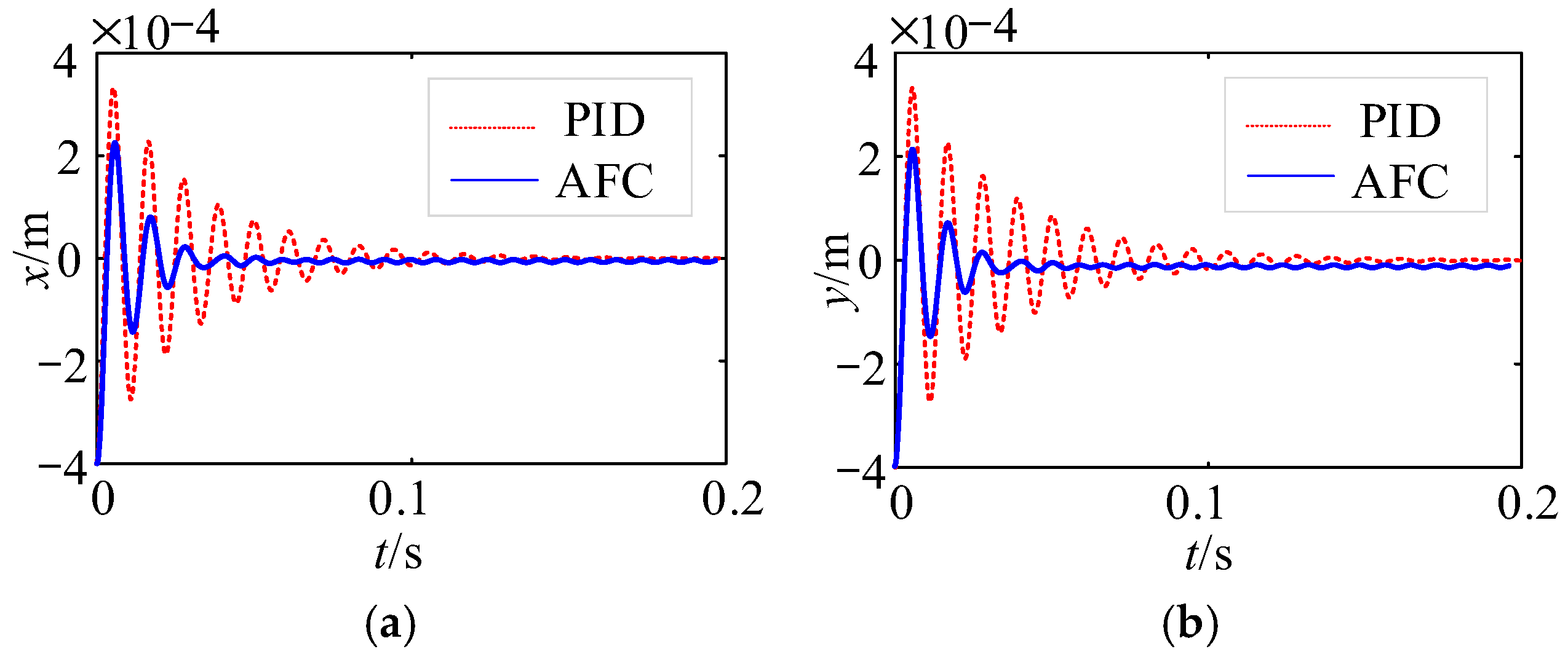
5.1. Suspension Control of the AMBs Rigid Rotor System

In the AMB rigid rotor system, the analysis of the suspension waveform of the rotor reflects the dynamic response and control effect of the system. The impacts of different control strategies on systemic stability are observed by comparing PID control and AFC. As shown in Figure 7, under the PID control, the maximum vibration displacement of the rotor is 3.2 × 10⁻⁴ m, and the system enters a stable state after approximately 0.17 s. When using the AFC, the maximum vibration displacement is reduced to 2.3 × 10⁻⁴ m, and the stability of the system is significantly better than that when using the PID control, quickly stabilizing after about 0.06 s.
In addition to the performance of rotor vibration displacement, the rotor center of mass displacement is also an important indicator for evaluating system performance. With the PID control, the maximum displacement of the rotor center of mass is within a circular range of 7.12 × 10⁻⁶ m, as shown in Figure 8a, and this shows the significant displacement fluctuations and slower response time of the system. With the AFC, as shown in Figure 8b, the maximum displacement of the rotor center of mass is significantly reduced to a circular range of 1.69 × 10⁻⁶ m, indicating that the AFC not only reduces rotor vibration but also significantly improves the stability of the center of mass position, optimizing the dynamic performance of the system.
From the perspective of the control effect, the AFC has significant advantages in reducing rotor vibration and accelerating systemic stability compared to traditional PID control. The AFC makes the system respond more accurately by adjusting the nonlinear and dynamic characteristics of the system in real time, which significantly improves the anti-interference ability and stability of the system. Therefore, the AFC is a more effective control strategy, especially for the AMB rigid rotor systems.

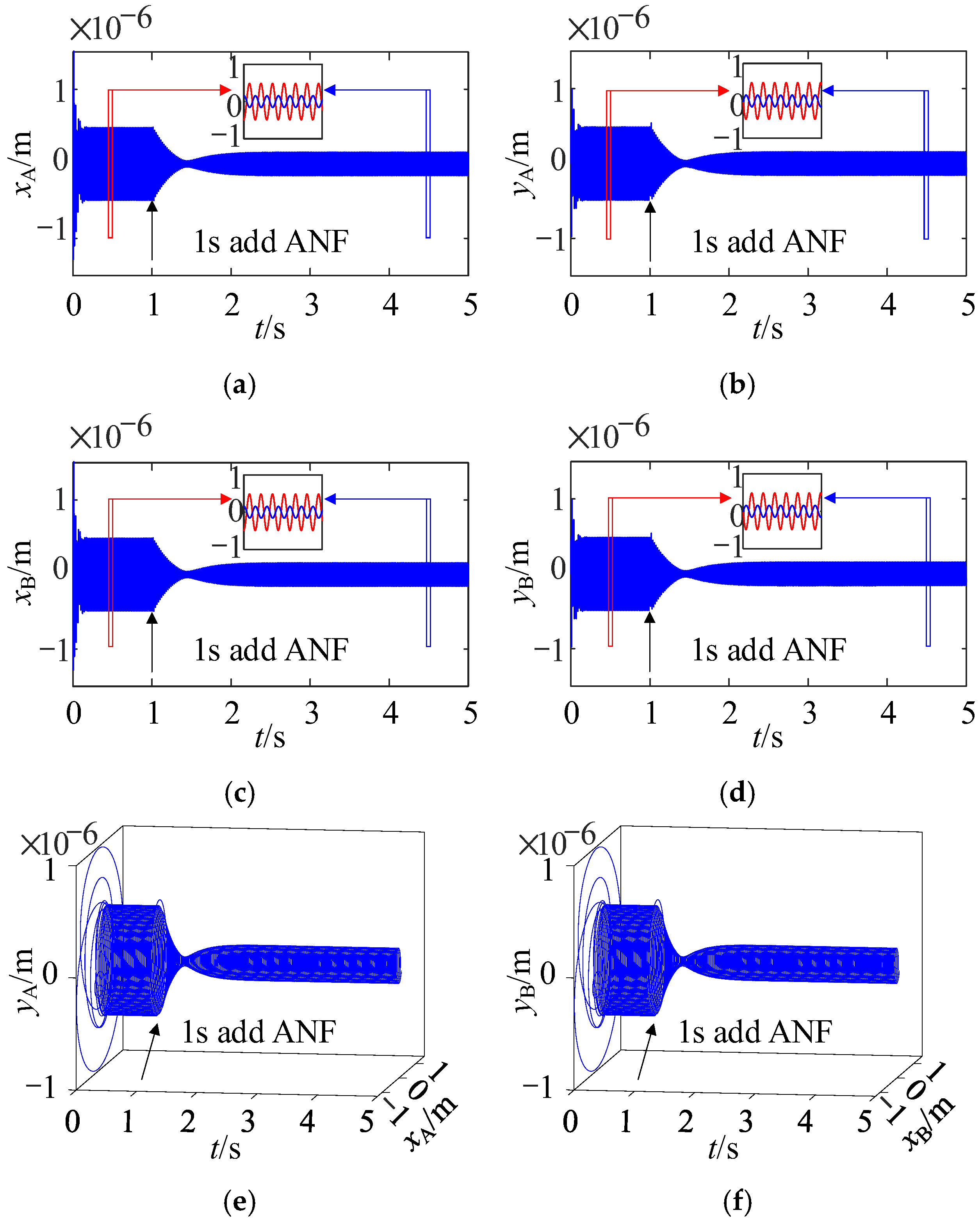
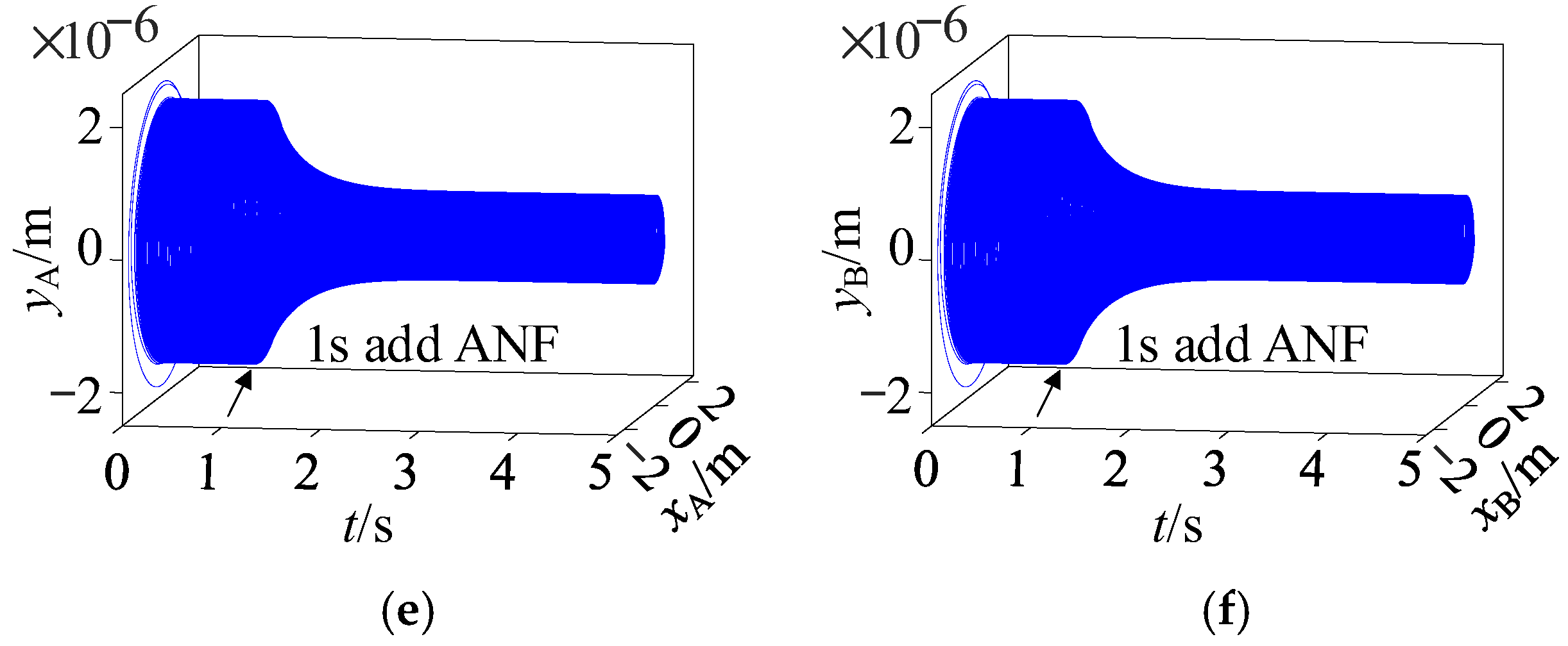
5.2. The Correctness Verification of AFC-ANF When the Rotor Runs at a Constant Speed

The control effect of rotor vibration control is verified in the case of positive polarity control and negative polarity control, as shown in Figure 9 and Figure 10.
In Figure 9a–f, it is evident that when the AMBs high-speed motor operates below the critical speed, the negative polarity control can reduce the rotor vibration from 0.51 × 10⁻⁶ m to 0.27 × 10⁻⁶ m at the AMB-A end, and the rotor vibration also reduces from 0.52 × 10⁻⁶ m to 0.27 × 10⁻⁶ m at the AMB-B end. Similarly, Figure 10a–f show that the vibration control effect of the AMBs rigid rotor system operates above the critical speed under the positive polarity control. Thus, the rotor vibration at the AMB-A end is reduced from 1.96 × 10⁻⁶ m to 0.66 × 10⁻⁶ m, reducing by 66.3%, and the rotor vibration at the AMB-B end is reduced from 1.97 × 10⁻⁶ m to 0.62 × 10⁻⁶ m, reducing by 68.5%.
Negative polarity control and positive polarity control are required when the rotor system is operated in the sub-stiff body critical speed region and super-stiff body critical speed region, respectively. Therefore, polarity-switching control is required when the rotor system is operated at full speed. The results also show that the rotor vibration displacement is reduced to a larger extent after the inclusion of the ANF, which effectively suppresses the unbalanced vibration of the rotor and proves the effectiveness of AFC-ANF for online unbalanced compensation.

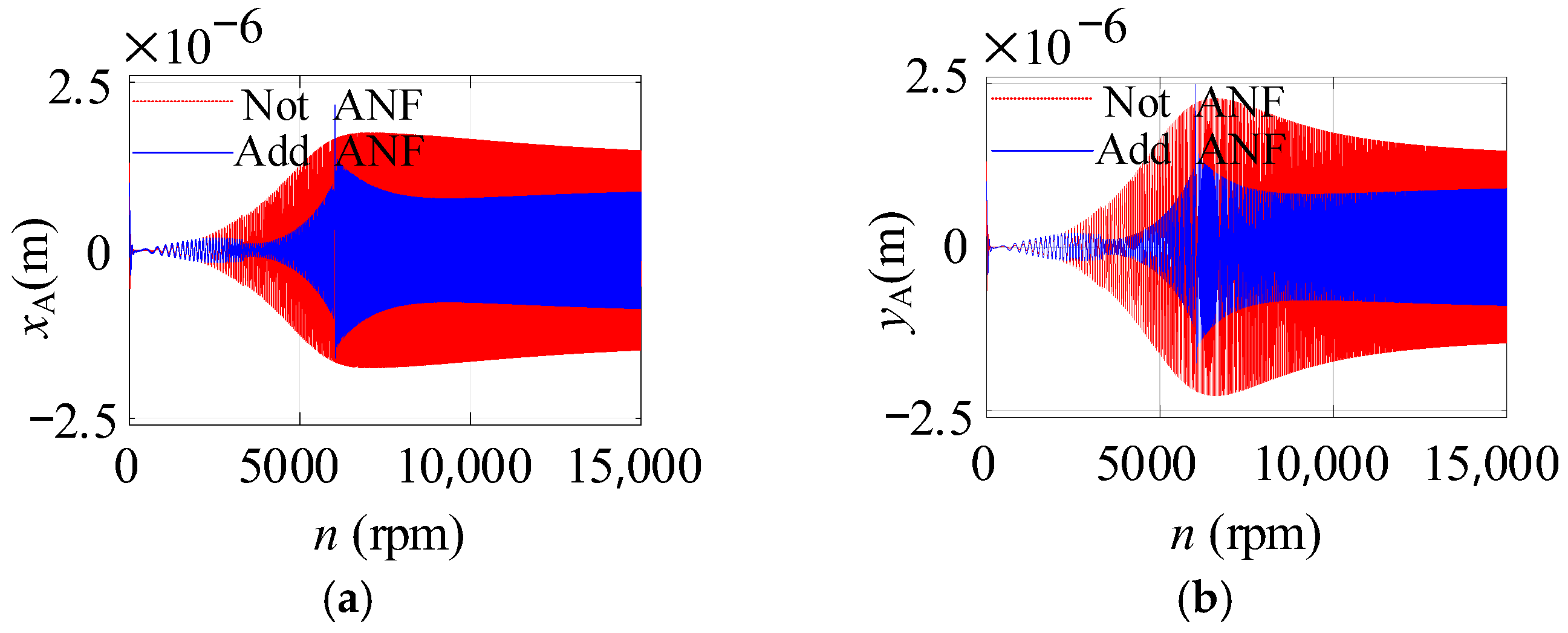
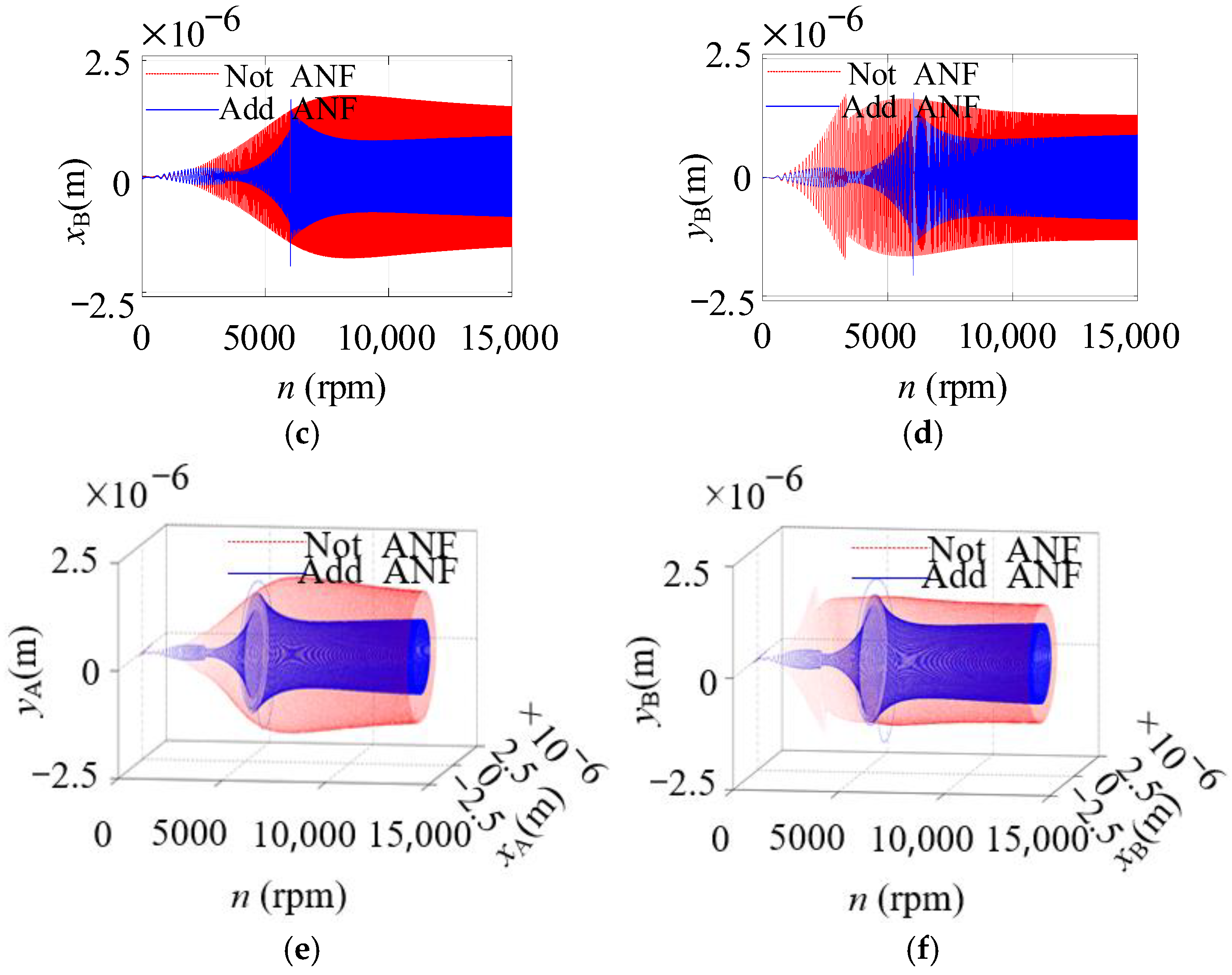
5.3. The Correctness Verification of AFC-ANF When the Rotor Is Under Acceleration

The ANF is added to the AFC of the AMBs rigid rotor system, which can filter out the signals present in the rotor vibration signals measured by the sensors that are of the same frequency as the rotational speed. Figure 11a–d show the rotor vibration of the AMBs rigid rotor system in constant-acceleration operation before and after the addition of ANF. Figure 11e,f show the 3D figure of rotor vibration of the AMB-A and AMB-B ends of the AMBs high-speed motor, respectively.
In Figure 11, it is observed that, under constant acceleration, the rotor vibration is significantly reduced due to the addition of the ANF, which reduces the rotor vibration at the AMB-A end from 1.5 × 10⁻⁶ m to 0.9 × 10⁻⁶ m, reducing by 40%; the rotor vibration at the AMB-B end reduces from 1.5 × 10⁻⁶ m to 0.9 × 10⁻⁶ m, reducing by 40%. After a short time, the rotor speed unbalanced component is filtered out to achieve unbalanced control, and the AFC-ANF does not change the stability of the AMBs-rigid rotor system, which also indicates that the AFC-ANF has a benefit-suppression effect on the unbalanced component.

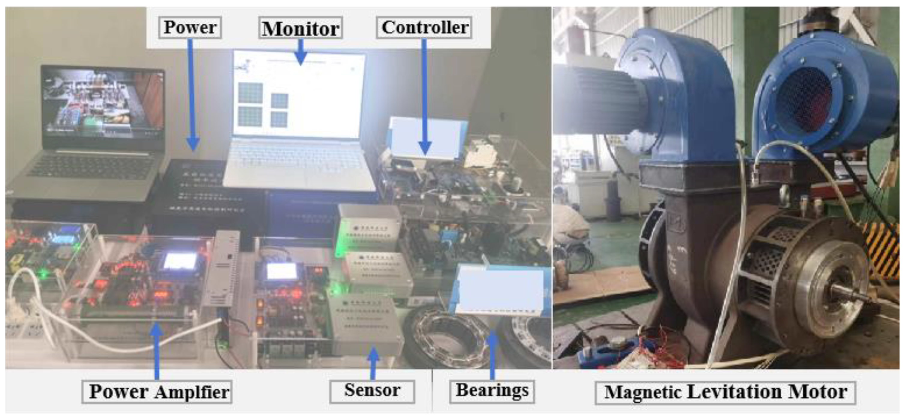
6. Experimental Results

The experimental setup for the AMB rigid rotor system is shown in Figure 12. This setup consists of several key components designed to support the experimental research and performance validation of high-speed active magnetic bearing (AMB) systems. A detailed description of each part of the experimental setup is given below:
The experimental setup consists of a monitor, a power supply, a power amplifier, a controller, a sensor, AMBs, and an AMB high-speed motor. This experimental setup is primarily used to study the vibration control issues in AMB systems during high-speed operations, particularly the dynamic performance under complex conditions such as rotor imbalance and critical speed passage. By comparing the experimental data with simulation results, the effectiveness of the control strategies can be validated.

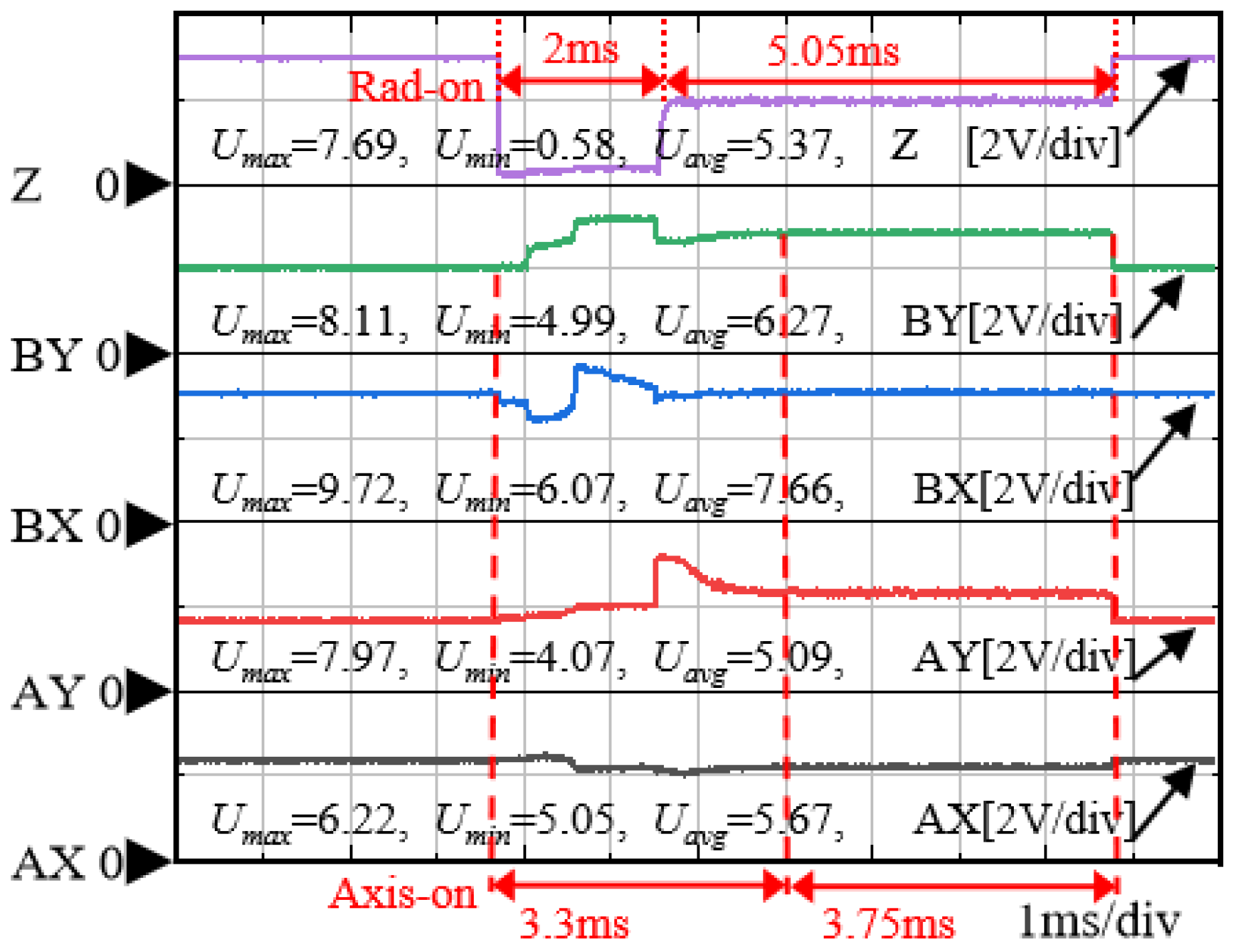
6.1. Experimental Results of Suspension Control of the AMB Rigid Rotor System

Figure 13 shows the floating process of the AMB high-speed motor, and evidently, the rotor can be stably suspended. The first four traces represent the voltage variations in the radial directions (BY, AY, BX, and AX), while the final trace corresponds to the axial (Z) direction. The horizontal axis is time (1 ms/div), and the vertical axis indicates the voltage (2 V/div). Each trace is annotated with the maximum voltage (Umax), minimum voltage (Umin), and average voltage (Uavg) to highlight the dynamic behavior in each direction.
The setting of the central voltage (AX, AY, BX, and BY) of rotor stable suspension is AX = 5.8 V, AY = 5.2 V, BX = 7.8 V, and BY = 6.3 V. During the initial phase (0 ms to 3.7 ms), the rotor remains in its natural state with no applied bias voltage, resulting in relatively stable voltage profiles across all directions. At 3.7 ms, a bias voltage is applied, initiating rotor motion. The radial voltage traces show a distinct transition, and the rotor achieves a stable levitation state approximately 7 ms later. At 10.75 ms, the bias voltage is removed, and the rotor returns to its natural state, with the voltage traces reverting to their initial values. The axial (Z-direction) response follows a similar trend, with the bias voltage applied at 3.7 ms, triggering a motion in the axial direction. The rotor stabilizes in the levitation state at 5.7 ms. The bias voltage is then removed at 10.75 ms, and the voltage returns to the natural state.

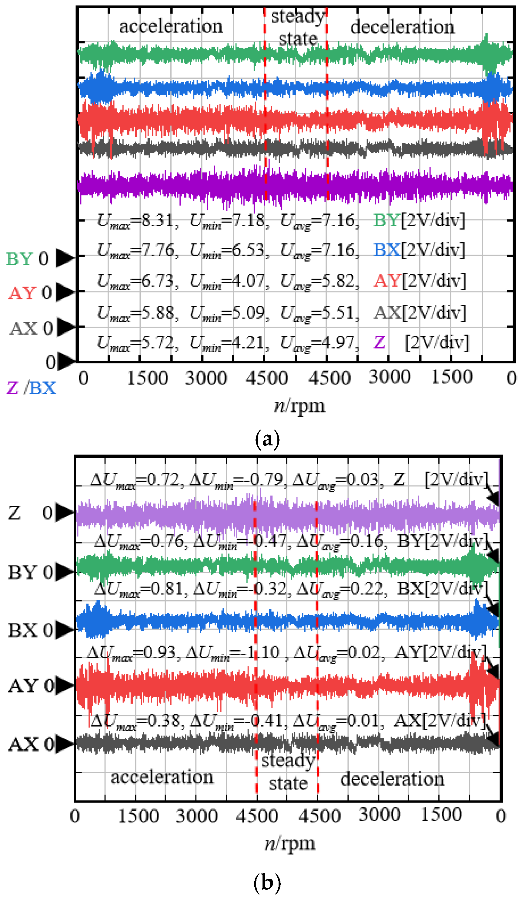
6.2. Acceleration Control of the AMB Rigid Rotor System

Figure 14a shows the rotor vibration of AMBs—the AMB rigid rotor system operating at 45,000 rpm. This figure depicts the vibration responses along the radial directions (AX, BX, BY, and AY) and the axial direction (Z) during the acceleration, steady-state operation, and deceleration stages. During the acceleration phase, the rotor may experience significant unbalanced forces and inertial forces, leading to an increase in the radial vibration amplitude, which stabilizes after reaching a peak. When the motor enters the constant-speed operation state (4500 rpm), the rotor typically achieves a stable condition with smaller radial vibration amplitudes, and fluctuation data indicate that the amplitude varies within a narrow range. During the deceleration phase, the rotor may again undergo changes in unbalanced and inertial forces, causing an increase in the radial vibration amplitude until the speed decreases from 4500 rpm to 0. The rotor vibration is expressed in volts, with the maximum (Umax), minimum (Umin), and average (Uavg) values annotated for each direction. A consistent scale of 2 V/div is applied for all signals. The magnetic levitation system employs sinusoidal currents in three-phase windings to generate the electromagnetic forces required for rotor suspension and stabilization. During the operation, the alternating force contributions from the phase windings result in periodic imbalances, which manifest as vibrations in the radial directions. These vibrations are more pronounced due to the dynamic nature of the electromagnetic forces. Contrarily, the axial vibration remains subdued, as the system consistently counteracts the gravitational load. The error between the rotor vibration and the neutral point is presented in Figure 14b.
Figure 14a illustrates the amplitude magnitudes of the radial four degrees of freedom (AX, AY, BX, and BY) and the axial direction (Z) during the acceleration to 4500 rpm, stabilization, and subsequent deceleration of the AMB high-speed motor. Figure 14b presents the maximum vibration values for each degree of freedom during acceleration, constant speed, and deceleration, providing a comprehensive understanding of the vibration behavior of the AMB high-speed motor under different operating conditions. Through the real-time monitoring and analysis of fluctuation data, the control system can achieve more precise adjustments, ensuring the stability and reliability of the motor across various operational states.
The 2D vibration plots provide a clear visualization of the rotor’s anisotropic vibrational characteristics, emphasizing the varying dynamic responses along different radial directions. In Figure 15a, the data indicate a notable discrepancy in the maximum vibration amplitudes, with AY reaching a peak value of 0.93 V compared to 0.38 V for AX. This disparity underscores the significant dynamic instability along the AY axis, potentially arising from uneven electromagnetic force distributions and transient imbalances during the rotor operation. Similarly, Figure 15b demonstrates a relatively balanced relationship between the maximum vibration amplitudes, with BX peaking at 0.81 V and BY at 0.76 V.
Figure 16 illustrates 3D vibration plots, providing a comprehensive visualization of the rotor’s dynamic behavior during operation. In both plots, the rotor speed is used as the horizontal axis (x-axis). In Figure 16a, AX and AY serve as the vertical (y-axis) and depth (z-axis) coordinates, respectively, showing the rotor’s vibration response during the acceleration, steady-state operation, and deceleration phases. This plot highlights the transient instabilities during the rotor’s startup phase, characterized by pronounced oscillations in both AX and AY. As the rotor speed increases, the vibrations gradually stabilize, reflecting the steady-state operation. During the deceleration phase, the increased vibration amplitudes in both AX and AY indicate the destabilizing effects caused by the rotor’s inertia and synchronization loss, effectively capturing the rotor’s dynamic fluctuations during speed transitions. These 3D vibration plots provide an in-depth perspective on the rotor’s dynamic characteristics under varying speed conditions.

7. Conclusions

This study addresses the issue of unbalanced vibration control in high-speed rigid rotor systems with active magnetic bearings (AMBs) by proposing an adaptive fuzzy control strategy based on a switching notch filter. The following conclusions are drawn based on theoretical analysis, simulation verification, and experimental research:
The proposed control strategy, which combines AFC-ANF, demonstrates significant vibration-suppression effects across the entire speed range. Simulation results indicate that, compared to the traditional PID control, the AFC reduces the system’s levitation stabilization time from 0.17 s to 0.06 s. The system employs negative polarity control for the notch filter near the rigid body critical speed frequency and positive polarity control above this frequency. When the AMB high-speed motor operates below the critical speed, the negative polarity control reduces the rotor vibration from 0.5 × 10⁻⁶ m to 0.27 × 10⁻⁶ m, a 46% reduction When operating above the critical speed, the positive polarity control reduces the rotor vibration displacement from 1.96 × 10 m to 0.66 × 10⁻⁶ m, a 66% reduction, effectively suppressing the unbalanced rotor vibration. During the constant acceleration, the rotor vibration displacement is reduced from 1.5 × 10⁻⁶ m to 0.9 × 10⁻⁶ m within a short period, a 40% reduction, quickly achieving rotor imbalance control. The experimental data further validate the effectiveness of this strategy, with stable levitation achieved within 3.3 ms after applying the bias voltage. At 45,000 rpm, the rotor vibration error voltage indicates the excellent dynamic response observed during the acceleration, steady-state operation, and deceleration phases. Therefore, the proposed AFC-ANF combined control strategy demonstrates significant advantages in vibration suppression and systemic stability, providing a new solution for the high-performance control of AMB rigid rotor systems.
Compared to the existing literature, the innovation of this study lies in the integration of fuzzy control with an adaptive notch filter, enabling the precise control of the AMB rigid rotor system across the entire speed range. However, this study has some limitations. For instance, the real-time computational complexity of the control strategy is relatively high, which may impose higher demands on hardware performance. Additionally, the impact of external disturbances (such as sensor noise) in the experimental environment on control effectiveness requires further investigation. Future studies could explore more efficient algorithm optimization methods to reduce the computational burden and extend this strategy to more complex multi-rotor or flexible rotor systems.
In summary, the proposed adaptive fuzzy control strategy based on a switching notch filter is not only theoretically innovative but also demonstrates superior performance in practical applications through simulations and experiments. This study provides a new solution for vibration control in AMB rigid rotor systems and lays a solid foundation for future studies in related fields.

Author Contributions

Conceptualization, L.G.; methodology, W.L. and Y.L.; software, J.C.; validation, Z.H. All authors have read and agreed to the published version of the manuscript.

Funding

This work was supported by the Natural Science Foundation of China (52407059) and the State Key Laboratory of Ocean Engineering (Shanghai Jiao Tong University grant No. GKZD010089). It was also supported by the Key Research and Development Process of Shaanxi (2024GX-YBXM-457), as well as the Shaanxi Postdoctoral Science Foundation (No. 2024BSHSDZZ226).

Data Availability Statement

Data are unavailable due to privacy or ethical restrictions.

Acknowledgments

The authors would like to thank the editors and reviewers for their contributions to our manuscript.

Conflicts of Interest

The authors declare no conflicts of interest.

Abbreviations

The following abbreviations are used in this manuscript:
AMBsActive magnetic bearings.
ANFAdaptive notch filter.
AFCAdaptive fuzzy controller.

Appendix A

Table A1. ΔKp, ΔKi, and ΔKd Fuzzy rules.
ECNBNMNSZOPSPMPB
E
NBPB/PS/NBPB/NS/NBPM/NB/NMPM/NB/NMPS/NB/NSZO/NM/ZOZO/PS/ZO
NMPB/PS/NBPB/NS/NBPM/NB/NMPS/NM/NSPS/NM/NSZN/SO/ZONS/ZO/ZO
NSPM/ZO/NBPM/NS/NMPM/NM/NSPS/NM/NSZO/NS/ZONS/NS/PSNS/ZO/PS
ZOPM/ZO/NMPM/NS/NMPS/NS/NSZO/NS/ZONS/NS/PSNM/NS/PMNM/ZO/PM
PSPS/ZO/ZMPS/ZO/NSZO/ZO/ZONS/ZO/PSNS/ZO/PSNM/ZO/PMNM/ZO/PB
PMPS/PB/ZOZO/NS/ZOZS/PS/PSNM/PS/PSNM/PS/PMNM/PS/PBNB/PB/PB
PBZO/PB/ZOZO/PM/ZONM/PM/PSNM/PM/PMNM/PS/PMNB/PS/PBNB/PB/PB

References

  1. Hutterer, M.; Wimme, D.; Schrödl, M. Stabilization of a Magnetically Levitated Rotor in the Case of a Defective Radial Actuator. IEEE/ASME Trans. Mechatron. 2020, 25, 2599–2609. [Google Scholar]
  2. Zheng, S.; Wang, C. Rotor Balancing for Magnetically Levitated TMPs Integrated with Vibration Self-Sensing of Magnetic Bearings. IEEE/ASME Trans. Mechatron. 2021, 26, 3031–3039. [Google Scholar]
  3. Zhou, M.; Shuai, Y.; Jiang, D.; Liu, Z. Active Magnetic Bearing PID Tuning with Model-Free Time-Domain Analysis Based Heuristic Algorithm. IEEE Trans. Ind. Inform. 2024, 20, 12157–12167. [Google Scholar]
  4. Yu, Y.; Yang, Z.; Han, C.; Liu, H. Fuzzy Adaptive Back-Stepping Sliding Mode Controller for High-Precision Deflection Control of the Magnetically Suspended Momentum Wheel. IEEE Trans. Ind. Electron. 2018, 65, 3530–3538. [Google Scholar]
  5. Xu, G.; Fu, Y.; Zhan, Y.; Wang, Z.; Zhao, H.; Zhang, Y. Influence of Different Rotor Damping Structures on Dynamic Characteristic of Dual-Excited Synchronous Generator with Excitation Control. IEEE Trans. Ind. Appl. 2023, 59, 6634–6644. [Google Scholar]
  6. Fang, L.; Ding, S.; Park, J.H.; Ma, L. Adaptive Fuzzy Control for Stochastic High-Order Nonlinear Systems with Output Constraints. IEEE Trans. Fuzzy Syst. 2021, 29, 2635–2646. [Google Scholar]
  7. Han, B.; Chen, Y.; Li, M.; Zheng, S.; Zhang, X. Stable Control of Nutation and Precession for the Radial Four-Degree-of-Freedom AMB-Rotor System Considering Strong Gyroscopic Effects. IEEE Trans. Ind. Electron. 2021, 68, 11369–11378. [Google Scholar]
  8. Ma, P.; Yu, J.; Wang, Q.G.; Liu, J. Filter- and Observer-Based Finite-Time Adaptive Fuzzy Control for Induction Motors Systems Considering Stochastic Disturbance and Load Variation. IEEE Trans. Power Electron. 2023, 38, 1599–1609. [Google Scholar]
  9. Chen, Y.; Du, L.; Sun, Q.; Bai, J.; Li, H.; Shi, Y. Self-Calibration Method of Displacement Sensor in AMB-Rotor System Based on Magnetic Bearing Current Control. IEEE Trans. Ind. Electron. 2024, 71, 5148–5156. [Google Scholar]
  10. Chen, S.Y.; Chiang, H.H.; Liu, T.S.; Chang, C.H. Precision Motion Control of Permanent Magnet Linear Synchronous Motors Using Adaptive Fuzzy Fractional-Order Sliding-Mode Control. IEEE/ASME Trans. Mechatron. 2019, 24, 741–752. [Google Scholar]
  11. Ren, G.P.; Chen, Z.; Zhang, H.T.; Wu, Y.; Meng, H.; Wu, D.; Ding, H. Design of Interval Type-2 Fuzzy Controllers for Active Magnetic Bearing Systems. IEEE/ASME Trans. Mechatron. 2020, 5, 2449–2459. [Google Scholar]
  12. Tang, Y.; Yang, P.; Yang, Y.; Zhao, Z.; Lai, L.L. Fuzzy Adaptive Frequency Support Control Strategy for Wind Turbines With Improved Rotor Speed Recovery. IEEE Trans. Sustain. Energy 2024, 115, 1351–1364. [Google Scholar] [CrossRef]
  13. Jing, Y.Z.; Feng, W.; Wang, S.; Ma, S.; Hao, J.; Dong, J. Levitation Control Strategy Based on Adaptive Non-singular Terminal Sliding Mode. J. Southwest Jiaotong Univ. 2022, 57, 566–573. [Google Scholar]
  14. Zuo, Y.; Ge, X.; Zhang, S.; Cao, H.; Wang, H.; Wang, Y.; Lee, C.H. Sensorless Control of IPMSM Drives Based on Extended State Observer with Enhanced Position Estimation Accuracy. IEEE Trans. Power Electron. 2025, 40, 787–800. [Google Scholar]
  15. Ye, J.H.; Shi, D.; Qi, Y.S.; Gao, J.H.; Shen, J.X. Vibration Suppression for Active Magnetic Bearings Using Adaptive Filter with Iterative Search Algorithm. CES Trans. Electr. Mach. Syst. 2024, 8, 61–71. [Google Scholar]
  16. Gong, L.; Zhu, C. Synchronous Vibration Control for Magnetically Suspended Rotor System Using a Variable Angle Compensation Algorithm. IEEE Trans. Ind. Electron. 2021, 68, 6547–6559. [Google Scholar]
  17. Yu, Y.; Shao, Y.; Chai, F.; Cui, M. Static-Errorless Position Estimation for Sensorless PMSM Drives with Enhanced Robustness Against the Full-Frequency Domain Disturbance. IEEE Trans. Power Electron. 2022, 37, 5884–5897. [Google Scholar]
  18. Zhang, Y.; Zheng, S.; Chen, Q.; Fang, J. Surge Detection Approach for Magnetically Suspended Centrifugal Compressors Using Adaptive Frequency Estimator. IEEE Trans. Ind. Electron. 2018, 65, 5733–5742. [Google Scholar]
  19. Ma, W.; Liu, G.; Zhou, J.; Han, X.; Zheng, S. Surge Detection of AMB-Supported Centrifugal Compressors Using a Normalized Adaptive Notch Filter. IEEE Trans. Instrum. Meas. 2024, 67, 480–489. [Google Scholar]
  20. Peng, C.; Zhu, M.; Wang, K.; Ren, Y.; Deng, Z. A Two-Stage Synchronous Vibration Control for Magnetically Suspended Rotor System in the Full Speed Range. IEEE Trans. Ind. Electron. 2020, 67, 480–489. [Google Scholar]
  21. Borque Gallego, G.; Rossini, L.; Achtnich, T.; Araujo, D.M.; Perriard, Y. Novel Generalized Notch Filter for Harmonic Vibration Suppression in Magnetic Bearing Systems. IEEE Trans. Ind. Appl. 2021, 57, 6977–6987. [Google Scholar]
  22. Gong, L.; Zhu, C. Vibration Suppression for Magnetically Levitated High-Speed Motors Based on Polarity Switching Tracking Filter and Disturbance Observer. IEEE Trans. Ind. Electron. 2021, 68, 4667–4678. [Google Scholar]
  23. Zhong, Y.; Zhou, J.; Zhang, Y.; Zhou, Y.; Xu, Y. Modelling and vibration response of a magnetically suspended flexible rotor considering base motion. Appl. Math. Model. 2023, 118, 518–540. [Google Scholar] [CrossRef]
Figure 1. Structure of AMBs-rigid rotor system.
Applsci 15 03681 g001
Figure 2. Schematic diagram of rotor imbalance.
Applsci 15 03681 g002
Figure 3. Schematic diagram of AMBs-rigid rotor system with fuzzy control.
Applsci 15 03681 g003
Figure 4. The triangular membership functions of the input and output variable domain and the characteristic surface plot. (a) Membership function of E. (b) Membership function of EC. (c) Membership function of ΔKp. (d) Characteristic surface plot of ΔKp. (e) Membership function of ΔKi. (f) Characteristic surface plot of ΔKi. (g) Membership function of ΔKd. (h) Characteristic surface plot of ΔKd.
Applsci 15 03681 g004
Figure 5. Equivalent block diagram based on adaptive ANF.
Applsci 15 03681 g005
Figure 6. The control schematic diagram of the AFC-ANF for the AMBs rotor system.
Applsci 15 03681 g006
Figure 7. Suspension waveform of the rotor. (a) Rotor vibration of x-direction. (b) Rotor vibration of y-direction.
Applsci 15 03681 g007
Figure 8. Displacement of center of mass. (a) PID control. (b) AFC.
Applsci 15 03681 g008
Figure 9. Rotor vibration with or without negative polarity control. (a) x direction of AMBs-A. (b) y direction of AMBs-A. (c) x direction of AMB-B. (d) y direction of AMB-B. (e) A 3D plot of AMB-A. (f) A 3D plot of AMB-B.
Applsci 15 03681 g009
Figure 10. Rotor vibration with or without positive polarity control. (a) x direction of AMBs-A. (b) y direction of AMBs-A. (c) x direction of AMB-B. (d) y direction of AMB-B. (e) A 3D plot of AMB-A. (f) A 3D plot of AMB-B.
Applsci 15 03681 g010aApplsci 15 03681 g010b
Figure 11. Rotor vibration under constant acceleration. (a) x direction of AMBs-A. (b) y direction of AMBs-A. (c) x direction of AMB-B. (d) y direction of AMB-B. (e) A 3D plot of AMB-A. (f) A 3D plot of AMB-B.
Applsci 15 03681 g011aApplsci 15 03681 g011b
Figure 12. Experimental rig.
Applsci 15 03681 g012
Figure 13. Floating process of the AMB high-speed motor.
Applsci 15 03681 g013
Figure 14. The rotor vibration of AMB-rigid rotor system operating at 45,000 rpm. (a) Rotor axial and radial vibrations. (b) Rotor vibration error.
Applsci 15 03681 g014
Figure 15. A 2D plot of rotor radial vibration. (a) Rotor vibration of AMB-A. (b) Rotor vibration of AMB-B.
Applsci 15 03681 g015
Figure 16. A 3D plot of rotor radial vibration. (a) Rotor vibration of AMB-A. (b) Rotor vibration of AMB-B.
Applsci 15 03681 g016
Table 1. Parameters of the AMB (active magnetic bearing) rigid rotor system.
SymbolMeaningValue
mRotor mass (kg)18.09
JMoment of inertia about x and y axes (kg·m2)0.2
la and lbDistance from ends A and B to the central plane (m)0.13
kiCurrent stiffness coefficient (N/A)577.96
khDisplacement stiffness coefficient (N/m)2.75 × 106
Disclaimer/Publisher’s Note: The statements, opinions and data contained in all publications are solely those of the individual author(s) and contributor(s) and not of MDPI and/or the editor(s). MDPI and/or the editor(s) disclaim responsibility for any injury to people or property resulting from any ideas, methods, instructions or products referred to in the content.

