1. Introduction
Space division multiplexing (SDM)-based free-space optical (FSO) links have garnered significant attention in recent years due to their potential to address the growing demand for high-capacity communication networks [
1,
2,
3,
4]. These links aim to effectively overcome the last-mile connectivity challenge by efficiently bridging the gap between end users and the installed fiber infrastructure [
5]. To further enhance this approach, a hybrid mode division multiplexing (MDM)-FSO bidirectional link can be implemented. This hybrid system offers a reliable and scalable solution for fiber-to-the-home (FTTH) applications, ensuring high-speed, cost-effective, and flexible connectivity to meet the increasing data traffic demands of modern households and businesses [
2,
4,
6].
Such systems leverage the unique advantages of MDM technology, including improved spectral efficiency and channel capacity, combined with the flexibility of FSO links in overcoming geographic and infrastructural constraints. By integrating these technologies, MDM-FSO links not only address bandwidth limitations but also provide a resilient alternative in areas where traditional fiber deployment is challenging or cost-prohibitive.
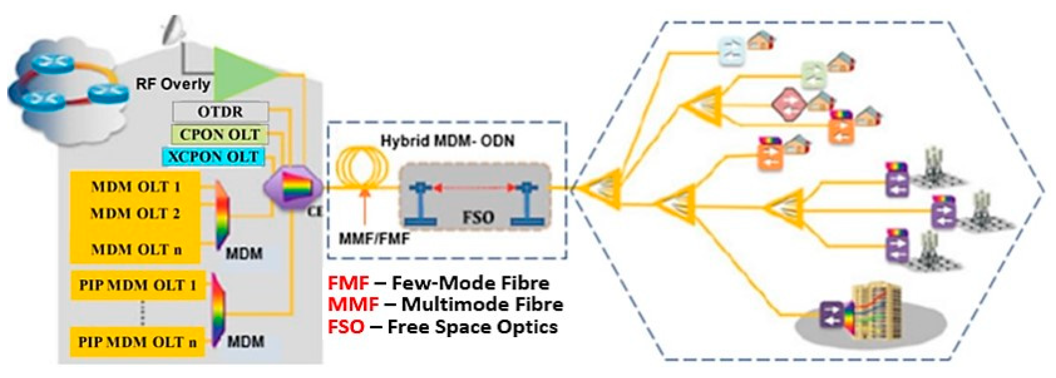
Figure 1 illustrates the proposed hybrid MDM-FSO architecture and its potential application in FTTH networks.
The deployment illustrated in
Figure 1 highlights a section of the MDM network that uses three-mode fiber as independent channels. It takes into account key parameters such as the number of spatial modes (applied to both MMF and FMF), modal dispersion, mode coupling, and mode-dependent loss (MDL). Additionally, factors like crosstalk between modes, fiber geometry, operating wavelength, and signal modulation format are considered, as they all have an impact on the capacity and transmission quality of the MDM system. An FSO link is employed under certain atmospheric conditions to address disruptions in a wired segment. A power splitter/mode multiplexer is implemented, which features one input and multiple outputs corresponding to the number of modes that the FSO link is intended to replace, depending on the specific type of channel (LP
01, LP
11, LP
02). Finally, the quality of the signal within the network is assessed at the receiver level using a demultiplexer and mode selector.
Different MDM signals can be transmitted through spatially engineered fibers, enhancing channel capacity and spectral efficiency [
7,
8]. For the final meters of a communication link, high-capacity free-space optical (FSO) technology serves as an effective solution, particularly in scenarios where deploying telecommunication fiber cables is impractical or cost-prohibitive [
8]. FSO technology is a notable application in establishing connections between offices within the same building or across university campuses, where short-range, high-speed links are essential. Telecom carriers have been making substantial investments in boosting the capacity of fiber backbones. However, to maximize the potential of FSO’s existing capabilities and enhance revenue generation, this backbone expansion must be complemented by a comparable increase in data demand and accessibility at the network edge, where numerous end users connect to the system [
9]. MDM-based FSO systems represent a promising solution for addressing these demands and can be implemented in a variety of scenarios. Specific applications include long-range wireless metropolitan area networks (WMANs), cellular backbones [
10,
11], and seamless connectivity between WLAN networks on campuses and in enterprise environments.
Moreover, FSO technology is highly adaptable and versatile, making it an excellent choice for wireless video surveillance and monitoring systems and for delivering broadband services to underserved or remote areas. Due to its ease of installation, flexibility, and re-deployable nature, FSO is particularly well-suited for disaster recovery scenarios, providing rapid and reliable connectivity when traditional infrastructure is damaged. Additionally, FSO links can play a pivotal role in establishing redundant communication pathways, enhancing overall network resilience.
MDM-FSO is a promising approach for increasing broadband penetration while providing cost-effective solutions for transmitting multiple RF signals over a high-speed optical carrier using inexpensive fiber cabling. This hybrid approach integrates the advantages of MDM systems and FSO technology, offering a robust, scalable, and efficient alternative for high-capacity communication networks [
12,
13].
MDM-FSO systems present a license-free RF solution, making them particularly attractive for areas with regulatory or financial constraints. Unlike conventional RF communication, which often requires frequency licensing, FSO links transmit signals through the atmosphere rather than optical fibers, effectively eliminating the high costs associated with fiber installation in densely populated urban environments. This feature enhances their feasibility in urban settings while reducing overall deployment costs [
2].
In regions where wireless radio technology faces challenges—such as mountainous terrains or areas with limited access to traditional infrastructure—FSO links can be integrated with existing mobile cellular radio networks. This combination enables rapid and reliable deployment of pervasive wireless systems, addressing connectivity gaps in hard-to-reach locations [
7]. Furthermore, FSO technology offers a higher degree of security due to its narrow beamwidth and immunity to electromagnetic interference, making it ideal for sensitive applications.
By combining the spectral efficiency of MDM systems with the flexibility and cost-effectiveness of FSO technology, MDM-FSO systems hold significant potential to revolutionize broadband connectivity, addressing challenges in urban, remote, and rugged terrains alike.
Although MDM-FSO-based systems have the potential to guarantee high-speed data rates, several critical challenges must be addressed to optimize their performance. These challenges include power sharing among mode channels, optical filter optimization, and the effects of atmospheric turbulence and scintillations [
14]. These factors significantly impact the signal-to-noise ratio (SNR) of the MDM-FSO link, necessitating the development of advanced solutions to mitigate these issues [
3,
4].
By integrating MDM with FSO technology, referred to as MDM-FSO, a seamless and cost-effective pathway for enhancing the capacity of existing wireless networks can be realized. This integration enables continuous collaboration with RF wireless networks, offering a scalable approach to meet the demands of modern communication systems [
5].
In addition to conventional binary modulation techniques such as non-return-to-zero (NRZ) and return-to-zero on-off keying (RZ-OOK), duobinary modulation is increasingly recognized as an effective format for overcoming bandwidth and multipath challenges [
15,
16,
17,
18]. Duobinary modulation reduces bandwidth requirements compared to OOK for a given data rate by intentionally introducing controlled inter-symbol interference (ISI) via pulse-shape filters at the transmitter [
19]. Adopting MDM-based duobinary modulation with FSO links can achieve medium- and long-haul transmissions with higher data rates, making it a promising solution for high-capacity optical communication networks [
6,
7,
8,
9,
10,
11].
This paper examines the performance of duobinary (DB) and modified duobinary (MDB) schemes for intensity modulation/direct detection (IM/DD) MDM-FSO systems. The adoption here is because of their power efficiency, high receiver sensitivity, and low complexity in equalization [
20,
21]. Key performance metrics include mode power sharing, system component optimization, and bit error rate (BER) at varying transmission distances. Experimental results compare various MDB schemes using the proposed link. Findings demonstrate that an MDM-FSO link employing MDB with NRZ modulation exhibits superior performance and greater tolerance to degradations caused by self-phase modulation (SPM) and modal dispersion. Further analysis reveals that MDB MDM-FSO systems using RZ signals show higher received power sensitivity than those using NRZ signals, making them particularly effective for long-distance transmissions.
To enhance the performance of the proposed MDM-FSO systems utilizing duobinary modulation, the following step-by-step procedure is adopted in this study:
The process begins by systematically adjusting the bias voltage applied to the two LiNbO3 modulators to achieve the optimal operating point, which maximizes signal fidelity while minimizing error rates. This adjustment is critical for maintaining stable modulation performance, as deviations from the optimal bias can lead to signal distortion and increased bit error rates.
A structured approach, involving iterative testing and analysis, is employed to identify the bias point that provides the best modulation characteristics until the optimal bias voltage is established. This process includes continuously monitoring key performance metrics such as extinction ratio, signal-to-noise ratio (SNR), and bit error rate (BER) to ensure precise modulation. Advanced optimization techniques, such as machine learning algorithms and artificial intelligence (AI) as well as adaptive control loops, can further enhance the accuracy of bias voltage tuning, leading to improved system stability and overall performance which will be considered for our future research.
The next step is to evaluate the duobinary modulation scheme, which is recognized for its spectral efficiency and resilience to intersymbol interference. Its implementation can be systematically benchmarked against more advanced multi-dimensional modulation free-space optical (MDM-FSO) architectures by analyzing key performance parameters such as bandwidth utilization, power efficiency, and error vector magnitude. Additionally, simulation and experimental validation can be conducted to assess its feasibility under different atmospheric conditions, ensuring optimal performance for high-speed optical communication systems.
Additional performance metrics, such as BER and overall system capacity, are thoroughly assessed in this study to evaluate the effectiveness of the proposed modulation scheme. These metrics provide critical insights into signal integrity, transmission reliability, and spectral efficiency.
2. MDM-Duobinary (MDM-DB) and MDM-Modified Duobinary (MDM-MDB) Formats
The duobinary modulation (DB) technique deliberately introduces intersymbol interference (ISI) by overlapping data signals from adjacent bits, effectively compressing the signal bandwidth while maintaining data integrity. This is achieved by adding a data sequence to a one-bit delayed version of itself, creating a correlation between successive bits [
22]. The modified duobinary (MDB) scheme extends this principle by incorporating a two-digit span correlation, further optimizing signal performance and bandwidth utilization.
One notable feature of the MDB technique is its ability to compress bandwidth more effectively compared to conventional DB modulation. This compression is evident in the eye diagram of the MDB scheme, which appears narrower than that of DB, indicating a reduction in signal dispersion. Research has demonstrated that MDB schemes based on NRZ and RZ signals offer significant advantages over standard NRZ and RZ modulation formats. These advantages include enhanced spectral efficiency, improved tolerance to noise, and better overall system performance.
The pulse formation for DB and MDB schemes can be mathematically modeled using Equations (1) and (2), respectively, which define the relationship between the original data sequence and its delayed components [
23]. By leveraging these characteristics, MDB modulation provides a powerful tool for optimizing the performance of high-capacity optical communication systems, particularly in bandwidth-constrained or interference-prone environments.
DB pulse generation is accomplished using a duobinary precoder in combination with an NRZ or RZ pulse generator. To shape the generated pulse, an optical low-pass filter is connected to the bias point of the LiNbO3 Mach–Zehnder modulator (MZM). For direct detection of DB-based MDM pulses, a spatial PIN photodetector is utilized, ensuring accurate signal retrieval. In this configuration, the MDM-based FSO system is biased at the null point to enhance detection performance and minimize errors.
The generation of MDB-MDM pulses involves introducing an additional delay in the pulse shaping process, as illustrated in
Figure 2a. This added delay allows for enhanced spectral efficiency and improved control over ISI, making MDB modulation particularly suitable for high-capacity optical systems. The simulation setup for analyzing SPM effects is shown in
Figure 2b, where the interaction of SPM with the generated MDB pulses is examined. This analysis provides valuable insights into the nonlinear behavior of the system and its impact on overall performance.
By incorporating these techniques, MDM-based FSO systems employing DB and MDB modulation formats can achieve superior signal quality and robustness, paving the way for more efficient and reliable optical communication networks.
DB/MDB MDM-Transmitter Model
Figure 3a illustrates the MDM-MDB transmitter setup, which comprises pseudo-random bit sequence (PRBS) generators, DB-NRZ and MDB-NRZ modulators for respective configurations, spatial continuous-wave (SCW) lasers, optical filters, and an optical mode combiner (MC). The PRBS generator produces a pseudo-random bit sequence at 40 Gbps and 40 GHz for each mode, with a 2
9 − 1 bit sequence length. The spatial CW lasers emit equally spaced wavelengths in the 1549 nm to 1554 nm range, ensuring efficient wavelength allocation for the multiple modes. Two lithium niobate (LiNbO
3) dual-port modulators, each with an extinction ratio of 30 dB, are employed for modulation. For the MDB-NRZ configuration, an SCW laser generates the three modes, which are driven by a data modulator to produce the modulated optical signals. These signals serve as inputs to the three input ports of the optical mode combiner, which combines the modes into a single transmission channel. To minimize signal crosstalk between adjacent modes, an optical filter is used for each mode, ensuring high signal integrity and performance.
Figure 3b depicts the measured optical spectrum at the input, demonstrating distinct and well-defined wavelengths generated by the setup.
3. MDM-FSO System Simulation Setup Model
Figure 4 illustrates the proposed secure MDM-based modified duobinary free-space optics transmission system, modeled using OptiSystem 19.0 software. The system employs three MDB modulation channels, each carrying a 40 Gbps, 40 GHz signal, which are multiplexed onto three laser modes: LP
01, LP
11 mode, and LP
02. The combined signal is transmitted through a 13 km three-mode fiber, followed by a 1.1 km free-space optics (FSO) channel. A SCW laser is used to excite the three LP modes, as depicted in
Figure 4. The pseudo-random bit sequence (PRBS) generator produces 40 Gbps of data, which is subsequently modulated using an NRZ/RZ generator and a duobinary precoder with a delay of −1 bit. These MDB signals are processed through an electrical subtractor and further modulated at 7.5 GHz using a sine wave generator operating at 40 GHz. This setup demonstrates the capability of MDM-MBD-FSO systems to achieve high data rates and secure optical communication over both fiber and free-space channels, highlighting its potential for advanced optical communication applications.
The MDB signal is modulated using two LiNbO
3 modulators, driven by a SCW source on the LP modes. The signal is then transmitted through a three-mode fiber and subsequently over an FSO link. The FSO transmitter and receiver apertures are optimized to 20.2 cm and 16.3 cm, respectively, ensuring efficient signal transmission and reception. Following FSO transmission, a 40 GHz signal is introduced after the spatial photodiode for the final down-conversion of the signal. A decoder is then employed to demodulate the resulting electrical signal, enabling accurate data recovery.
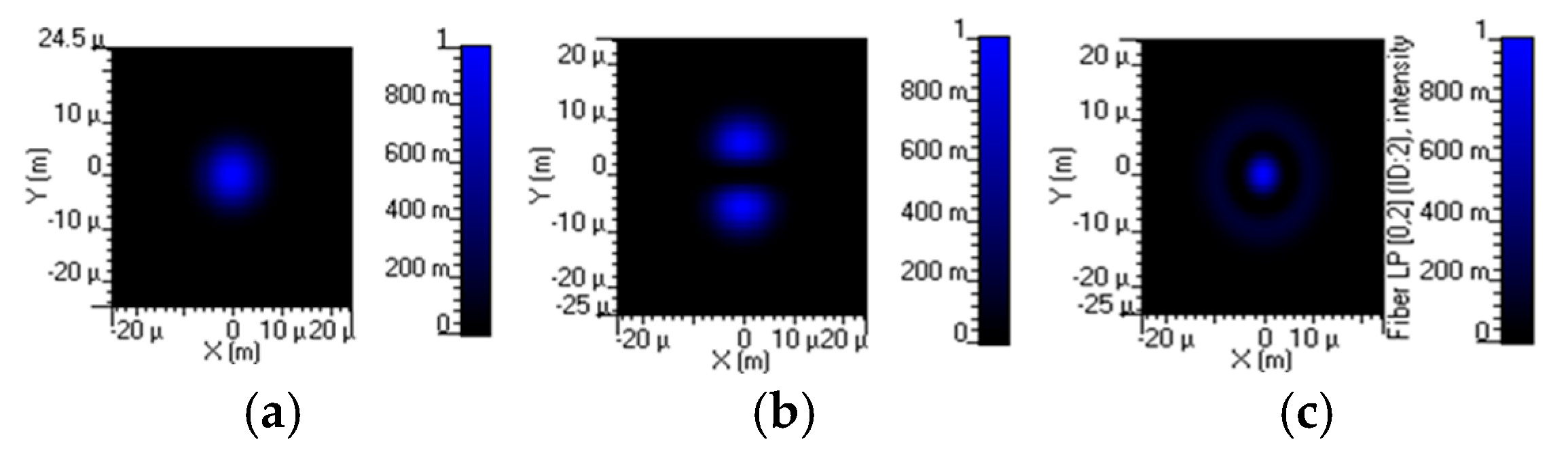
Figure 5 illustrates the three LP modes generated at the output, visualized using an optical visualizer, showcasing the distinct mode patterns achieved through the system.
The key parameters adopted for the three-mode fiber model used in this study are the core radius (a), cladding radius (b), core refractive index (n1), cladding refractive index (n2), and operating wavelength (λ). These features are crucial for calculating the normalized frequency (V-number), which determines the number of propagating modes in the fiber.
Table 1 summarizes some of the parameter values used for modeling the three-mode fiber.
The FSO link is similarly modeled using the parameters depicted in
Table 2 under specific predefined atmospheric conditions. The performance of the FSO communication link is verified by comparing the results of the proposed design with the measurement standards established by the Kim model [
24]. According to the Kim model, the acceptable minimum binary error rate in telecommunications is 10
−9, and the value of Quality Factor Q is approximately six [
25]. The link is modeled based on the assumption that thermal noise and background radiation noise are the primary noise sources. Ignoring signal-related noises, the relevant noise terms are presented in Equation (3).
The concepts of background light and background light beat noise are denoted by
, alongside the distinct representation of thermal noise
and shot noise
. Together, these elements play a crucial role in understanding the overall noise conditions.
Be denotes the electronic bandwidth of the system,
K denotes the Boltzmann constant,
T is the temperature in Kelvin, and
RL represents the photodetector load resistance. The values of these system parameters are shown in
Table 2.
It is worth emphasizing that when a bias voltage is applied to a LiNbO
3 device, it causes a change in polarization that leads to different refractive indices for various optical modes in the waveguide. This variation can result in mode coupling [
26,
27], where energy is transferred between optical paths, affecting the link’s performance and efficiency. The extent of mode coupling depends on the magnitude and orientation of the applied electric field. If the bias voltage aligns with the crystal’s principal optical axis, it can enhance certain modes while suppressing others, allowing for tailored spectral properties. However, misalignment can cause unwanted scattering and loss, compromising signal integrity. Moreover, the nonlinear nature of the electro-optic effect in LiNbO
3 can introduce complexity into the analysis of mode coupling dynamics, especially at higher electric fields [
28]. This nonlinearity may result in phenomena such as SPM, where the effective refractive index changes with the intensity of the light, further intensifying mode interactions.
In summary, the interplay of electro-optic effects and mode coupling in LiNbO3 under varying bias voltages presents challenges and opportunities for optimizing optical devices, with ongoing research aimed at improving system performance.
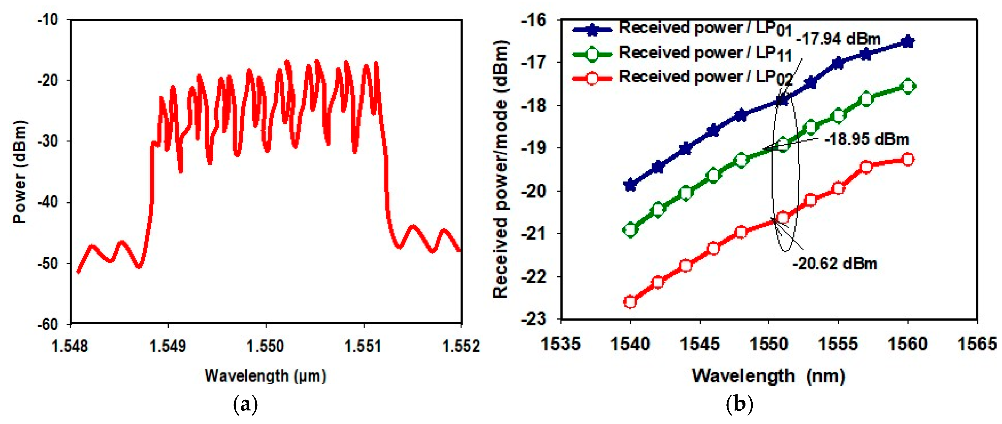
Figure 6a shows the post-fiber spectra at 40 Gbps after transmitting the combined mode signal over a 13 km link, with equally spaced channels. Modal dispersion and four-wave mixing were effectively mitigated in the 120-GHz-spaced MDM transmission, ensuring minimal degradation of system performance. The optical signal was then transmitted through the free-space optical (FSO) channel for further propagation.
Figure 6b illustrates the variation of mode power with wavelength; the received power at 1550 nm for the LP
01, LP
11, and LP
02 was evaluated to be −17.94 dBm, −19.985 dBm, and −20.62 dBm, respectively. This introduced a power penalty of 1.01 dB between LP
01 and LP
11 channels and 1.67 dB between LP
01 and LP
02 modes.
4. Results and Discussion
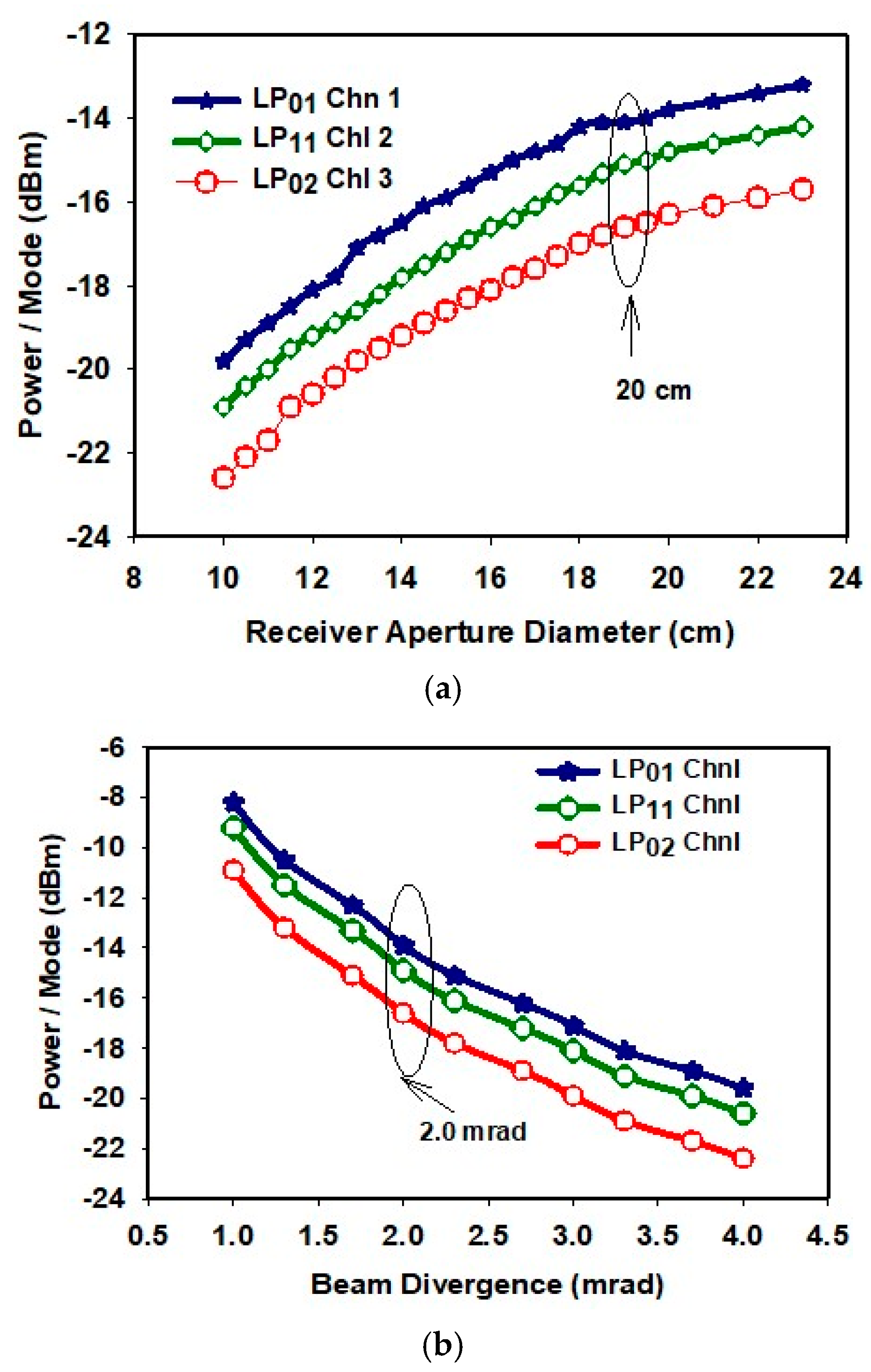
Figure 7 illustrates the impact of varying receiver aperture diameter and beam divergence on the received power per mode in the MDM-FSO link.
Figure 7a examines the effect of changes in receiver aperture diameter on the received power per mode. A significant increase in received power is observed as the receiver aperture size increases. The power ratio penalties across the three mode channels can be attributed to two primary factors: multipath dispersion and optical path loss. Consequently, careful optimization of the receiver aperture size is essential, as improper selection may adversely affect the power distribution among the transmission modes.
Figure 7b shows the effect of beam divergence variation on the received power per mode for the three MDM-FSO channels. The analysis reveals that the power penalty increases with the number of modes. For instance, at a reference beam divergence of 2 mrad, the LP01mode exhibits a received power of −13.78 dBm, while the LP11 and LP02 modes show received powers of −14.31 dBm and −16.8 dBm, respectively. This demonstrates that as beam divergence increases, the power received by higher-order modes is more significantly impacted, which must be taken into account when designing the MDM-FSO system.
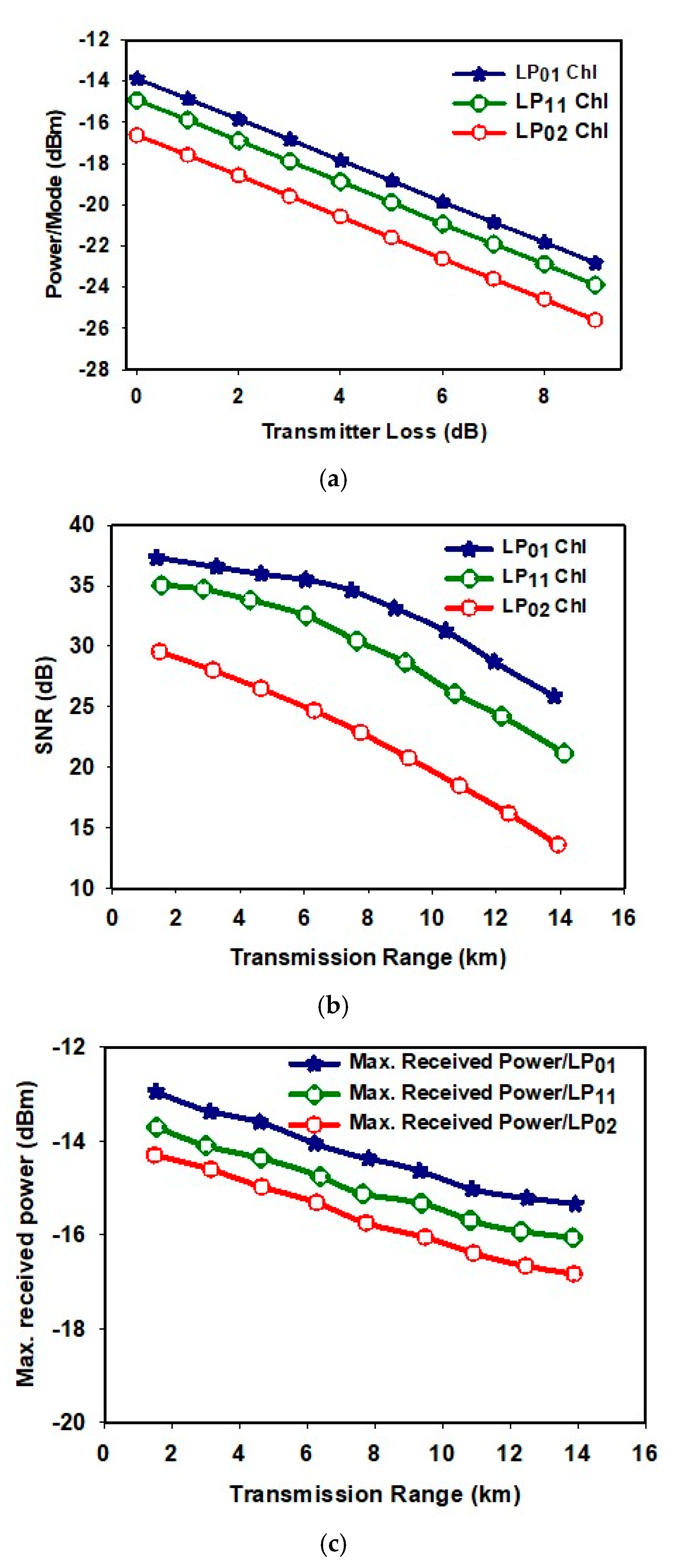
Figure 8a examines the impact of varying transmitter loss on the received power per mode. As transmitter loss increases, the energy received per mode decreases, indicating the need for careful optimization to select an appropriate value for transmitter loss to prevent performance degradation. In this study, the desirable value for transmitter loss is found to be approximately 0.6 dB for all three modes, at which point the transmission power received by the modes is maximized.
Figure 8b presents the signal-to-noise ratio (SNR) and maximum received power for the proposed MDB-MDM-FSO link model. The system performance was evaluated under clear weather conditions, demonstrating the potential of the link to deliver high-quality signal reception in ideal environmental conditions.
As shown in
Figure 8b, the SNR for the LP01 mode is calculated to be 37.13 dB, 36.11 dB, and 34.13 dB for transmission distances of 2 km, 4 km, and 12 km, respectively. For the LP11 mode, the SNR values are 35.11 dB, 33.12 dB, and 27.56 dB, while for the LP02 mode, the calculated SNR values are 27.11 dB, 24.11 dB, and 17.13 dB at the same distances.
This significant difference may be due to factors like mode crosstalk or fiber loss, indicating that the LP01 mode better preserves signal integrity. Mode crosstalk is one possible explanation. In MMFs, higher-order modes like LP02 tend to interact more with other modes, leading to increased interference and reduced signal fidelity. Additionally, the LP01 mode generally has a lower effective refractive index, which provides a more uniform light distribution. In contrast, the complex field distribution of the LP02 mode can result in greater coupling into the cladding, causing losses from scattering and absorption as distance increases. Other factors, such as the operating wavelength and fiber design, also influence modal behavior. For instance, in high-bandwidth fibers, the choice of mode can significantly impact the SNR.
In essence, while mode crosstalk and fiber loss help explain the difference in SNR between the LP01 and LP02 modes, further investigation is needed to quantify their effects. Understanding these dynamics is crucial for optimizing performance in FMF applications as network demands rise.
Figure 8c illustrates the total received power for each mode. For the LP01 mode, the received power is −13.24 dBm, −13.57 dBm, and −14.24 dBm at 2 km, 4 km, and 12 km, respectively. For the LP11 mode, the received power is −13.81 dBm, −15.82 dBm, and −15.95 dBm, while for the LP02 mode, the received power values are −14.29 dBm, −14.76 dBm, and −16.57 dBm at the corresponding distances. These results highlight the impact of transmission distance on both SNR and received power, with the performance gradually degrading as the link distance increases.
The results indicate that under clear weather conditions, the LP01 mode can extend beyond 14 km, the LP11 mode can reach up to 13 km, and the LP02 mode can transmit up to 12 km, all while maintaining tolerable SNR and maximum received mode power. Additionally, it is observed that the LP11 mode is more susceptible to fading effects compared to both the LP01 and LP02 modes. In summary, while all modes are subject to fading, the specific characteristics of the LP11 mode, its lobular structure, energy distribution, and coupling efficiency render it particularly vulnerable to fading effects, thus distinguishing it from the more stable LP01 and LP02 modes.
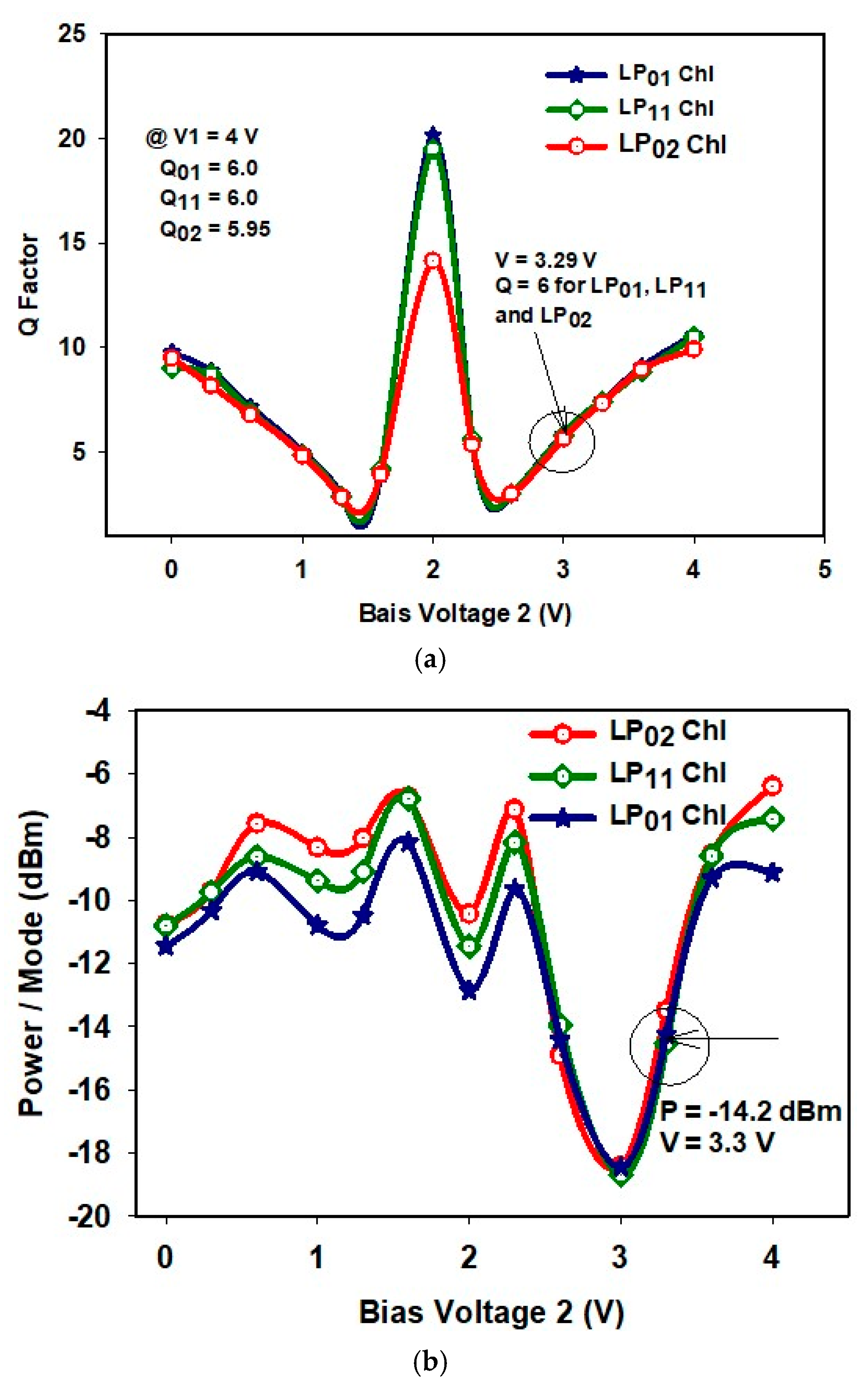
Figure 9a,b illustrate optimization techniques aimed at enhancing the Q-factor and improving power distribution across mode channels. In
Figure 9a, the Q-factor is shown to vary with the bias voltage (V2_22) applied to the second modulator, highlighting the system’s sensitivity to performance degradation as this voltage changes. Conversely,
Figure 9b demonstrates that power distribution among modes can be equalized to mitigate power penalties, with the received power fluctuating in response to adjustments in the bias voltage of the second LiNbO
3 modulator.
Both figures indicate that optimal performance is achieved at an approximate bias voltage of 3.2 V, where the Q-factor reaches a value of about six. Further analysis underscores the importance of maintaining the bias voltage within this optimal range to ensure consistent signal integrity [
29]. Deviations from the 3.2 V threshold lead to a significant decline in the Q-factor, adversely affecting the system’s error performance. This situation highlights the necessity for precise control mechanisms within modulation systems to minimize fluctuations caused by environmental or operational factors.
Additionally,
Figure 9b illustrates the effectiveness of the optimization strategies in achieving a more uniform power distribution across mode channels. By fine-tuning the bias voltage, the system can address discrepancies in power allocation, which is essential for preventing power penalties that could impact overall throughput. The relationship between modulator settings and power distribution emphasizes the delicate balance required to optimize channel performance.
The interaction between the Q-factor and power distribution metrics reveals the complex relationship between bias adjustments and performance outcomes, suggesting that a multifaceted approach is necessary for effective system optimization. Future research could investigate adaptive bias control techniques that automatically adjust in real time to maintain the Q-factor and power distribution within desired limits, ensuring robust performance under varying operational conditions.
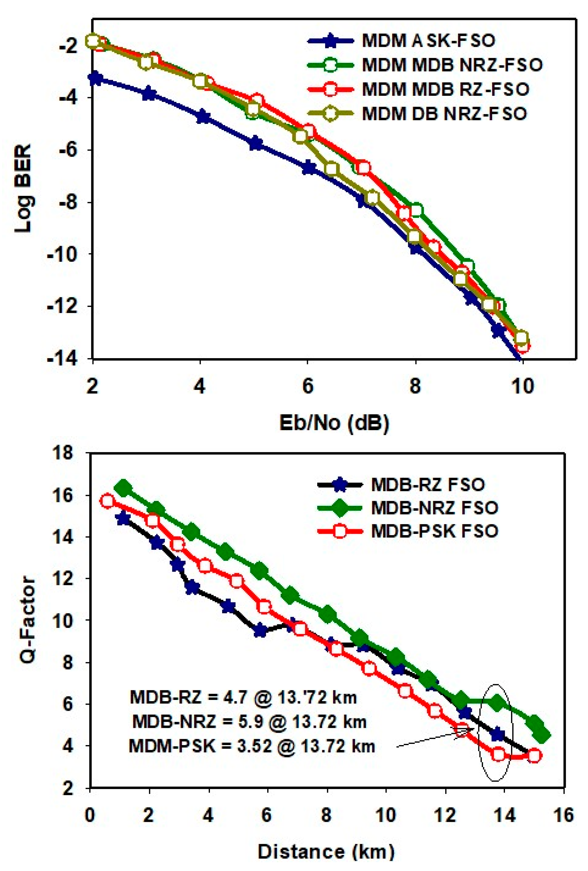
The BER for the ASK-FSO, DB NRZ-FSO, MDB RZ-FSO, and MDB NRZ-FSO links is presented in
Figure 10, which clearly shows that the DB schemes exhibit similar error performance, with a 0.8 dB error penalty relative to ASK-FSO.
Furthermore, as illustrated in
Figure 10, the MDB-FSO system based on the NRZ modulation format demonstrates greater resilience to increases in transmission distance. For instance, at a distance of 13.72 km, the measured Q-factors were found to be 5.9 for the MDB-NRZ link, 4.7 for MDB-RZ, and 3.52 for MDB-PSK.
Modes like LP01 and LP02 exhibit different susceptibility to SPM due to varying field distributions and effective core radii. LP01, as the fundamental mode, has a uniform power distribution, while LP02, a higher-order mode, shows more spatial intensity variation, leading to different responses to nonlinear interactions. Additionally, it is important to explore how changes in modal coefficients affect nonlinear effects, particularly in high-capacity optical fiber systems where signal integrity is crucial. Clarifying the relationship between mode shape, effective area, and power thresholds is necessary. An analysis using the nonlinear Schrödinger equation across modes could provide insights into the challenges faced by optical networks under high power conditions.
In essence, understanding these nonlinear coefficients enhances our knowledge of SPM’s role in optical performance and supports the development of modulation formats and designs that mitigate nonlinear phenomena, ultimately promoting system efficiency and reliability in lightwave communication technologies.
An analysis of SPM was conducted for the three mode channels of fiber, each operating at a data rate of 40 Gb/s with different modulation formats. The bandwidths of the electrical low-pass filter (LPF), optical band-pass filter (BPF), and optimized values for the LPF post-detection were selected. This analysis was based on the assumption that the optimal LPF bandwidth for a given bit rate (B) lies within the range of [0.28B, 0.42B]. For the DB MDM-FSO system using NRZ, the electrical LPF bandwidth was set to 15.24 GHz, while the optical BPF frequency was set to 27.92 GHz. Similarly, for the MDB MDM-FSO system, the LPF and BPF bandwidths were adjusted to 35.7 GHz and 45.6 GHz, respectively, as shown in the simulation setup in
Figure 2b.
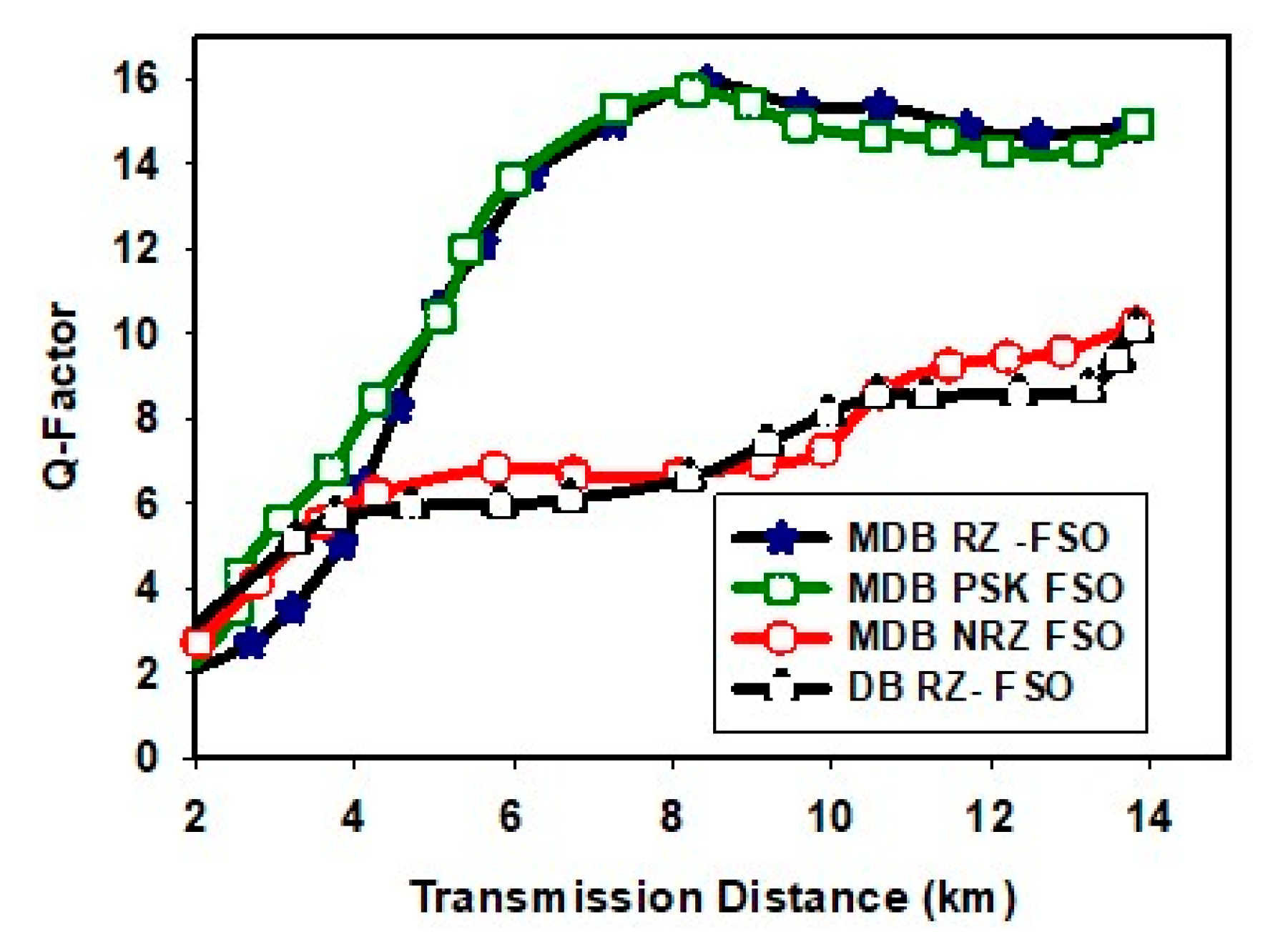
Figure 11 illustrates the effect of SPM at power levels ranging from −20 dBm to −4 dBm for the spatial CW laser. As the transmission distance increased, varying the bandwidth of the optical filter resulted in a degradation of the Q-factors. The analysis provides the optimized filter bandwidth necessary for the four-modulation model. A 13 km three-mode fiber was used for the SPM analysis, with an optimized attenuation value set to 1.2 dB/km.
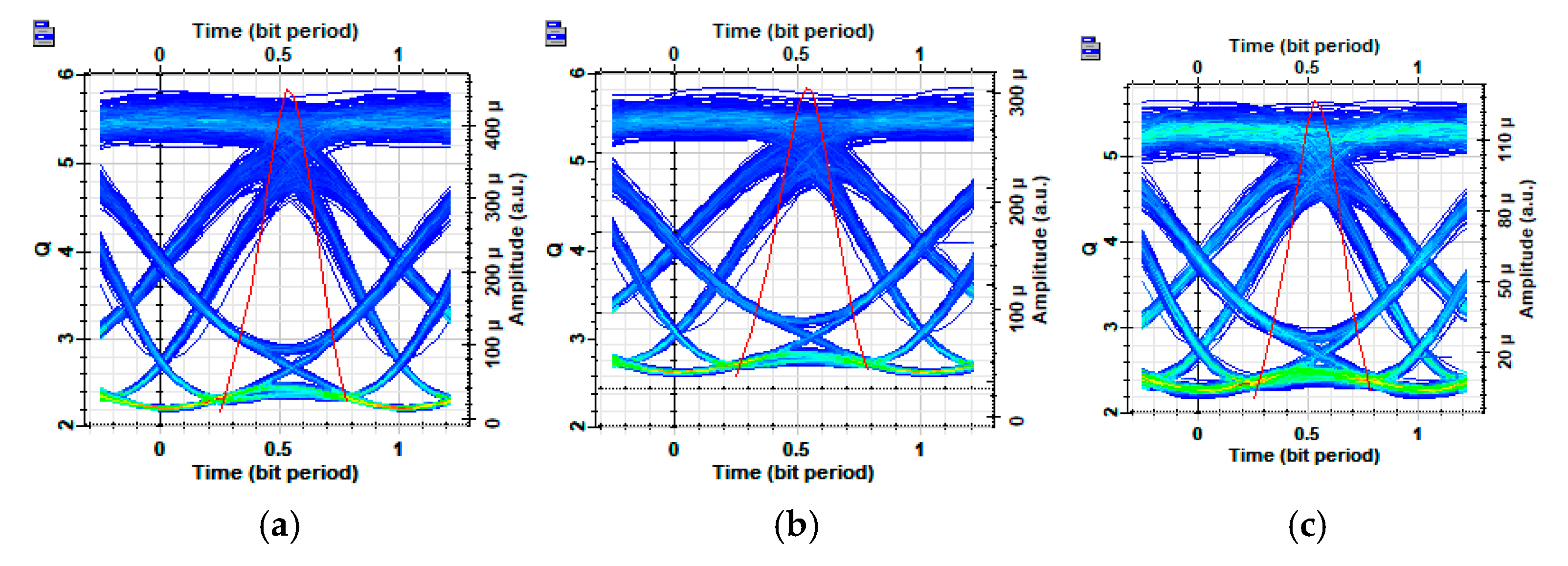
Figure 12 presents the optimized eye diagram for the MDM MDB-based FSO at a bit error rate (BER) of 10
−9, yielding a Q-factor of approximately six across the three mode channels.
It is crucial to mention that the basis for fiber length selection in the proposed MDM-FSO link encompasses thorough scrutiny of link budget evaluations alongside mode stability considerations. Mode stability is considered a vital factor in fiber length chosen in the adoption of the three spatial modes to encode information. The effective utilization of these modes requires stable propagation characteristics over the length of the fiber. Longer fibers may introduce modal dispersion and coupling losses, which can disrupt the integrity of the transmitted data. Consequently, in this study, an optimal fiber length was examined through simulations to ensure that the desired modal characteristics are preserved throughout the transmission distance. A maximum precise balance between ensuring adequate transmission distance and maintaining sufficient power levels at the receiver is achieved at 13 km three-mode fiber + 1.1 km FSO. Thus, the interplay of these factors not only ensures robust communication links but also enhances the overall efficiency and viability of the proposed MDM-FSO model in practical deployments.
As a recommendation for further work, the framework of edge-disjoint, rooted, distance-constrained minimum spanning trees can be employed to effectively optimize transmission paths, minimize interference, and enforce stringent constraints on latency and power efficiency [
30]. The utilization of AI to address other challenges, e.g., routing, fault tolerance, and optimal resource allocation can also be considered for future works.
5. Conclusions
In this study, we presented an optimized 120 Gbps three-channel free-space optical (FSO) system utilizing the space-division multiplexing (MDM) approach, incorporating various duobinary modulation formats. We demonstrated the optimization of power-sharing among transmission modes, employing different duobinary (DB) modulation formats to enhance system performance. Notably, the mitigation of the power penalty was shown to significantly improve the link’s overall performance. Additionally, the impact of SPM over 40 Gbps per channel was explored across multiple modified duobinary (MDB) formats.
Our analysis further included the optimization of optical low-pass filter bandwidths in response to variations in the Q-factor, providing critical insights for MDM-FSO links. The results reveal that the MDB MDM-FSO link, based on NRZ data modulation, outperforms other formats, exhibiting greater resilience to impairments such as SPM and modal dispersion. Moreover, optimized filter bandwidth values were achieved for MDB-modulated MDM-FSO formats, with ASK and NRZ-modified duobinary designs showing similar performance trends.
Further investigation into optical received power sensitivity across different formats is recommended to determine the most suitable format for practical deployment. Our findings also indicate that MDB MDM-FSO RZ signals demonstrate superior received power sensitivity when compared to MDB MDM-FSO NRZ signals, making them a potentially more robust choice for high-capacity optical systems.
The numerical analyses conducted in this study can serve as a foundation for future research aimed at optimizing filter parameters for MDM-based FSO systems utilizing duobinary and modified duobinary modulation. By identifying the best system configuration to mitigate SPM and modal dispersion-induced impairments at specified input launch powers, we can significantly improve the overall performance and reliability of MDM-based FSO systems.


